Adaptive Sliding Mode Control Based on Disturbance Observer for Placement Pressure Control System


Abstract
1. Introduction
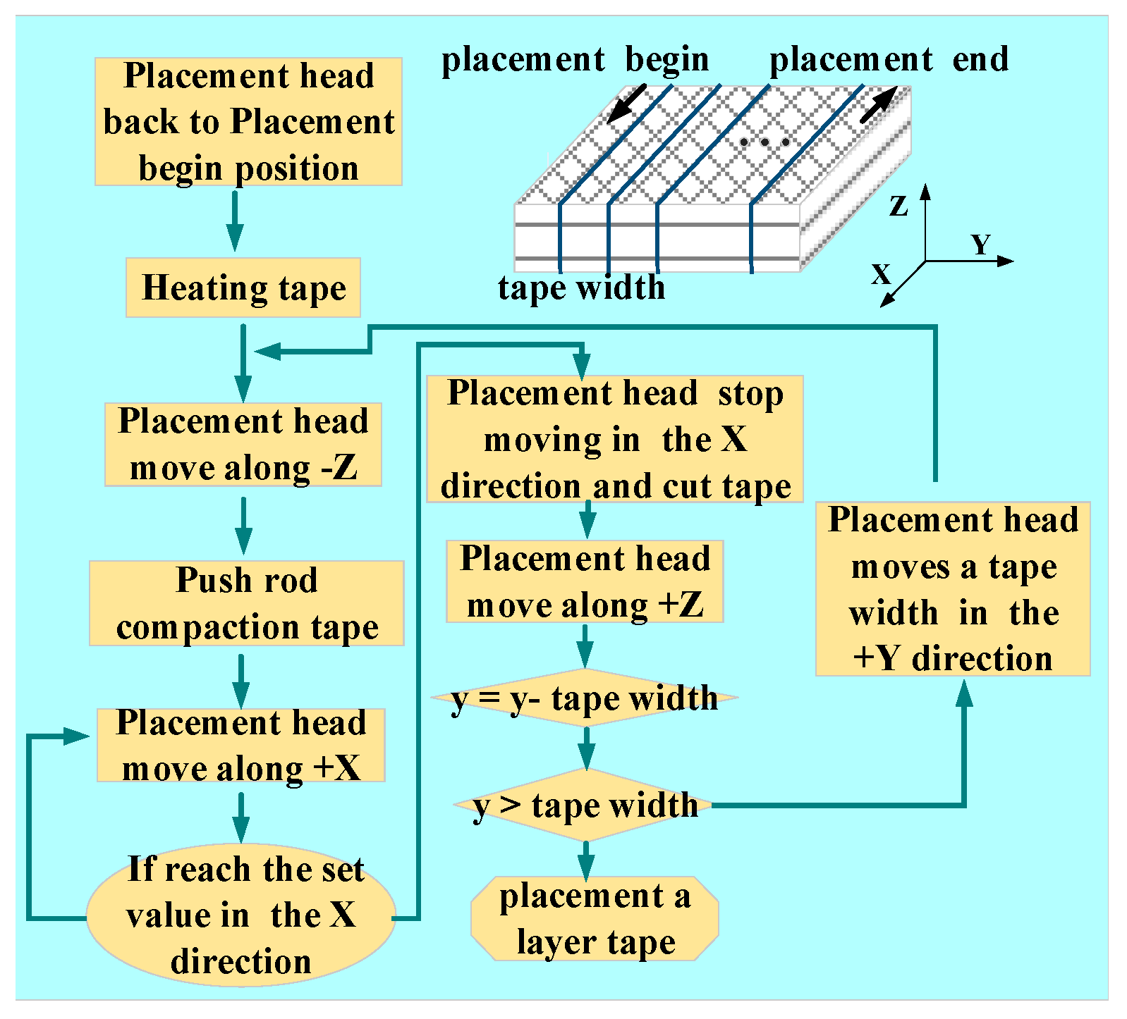
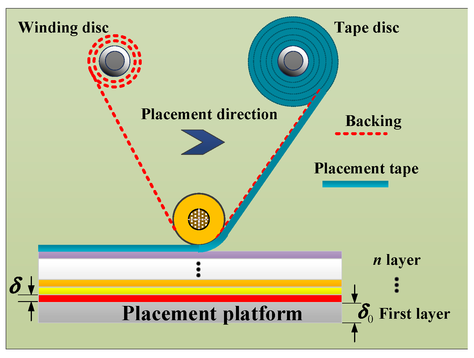
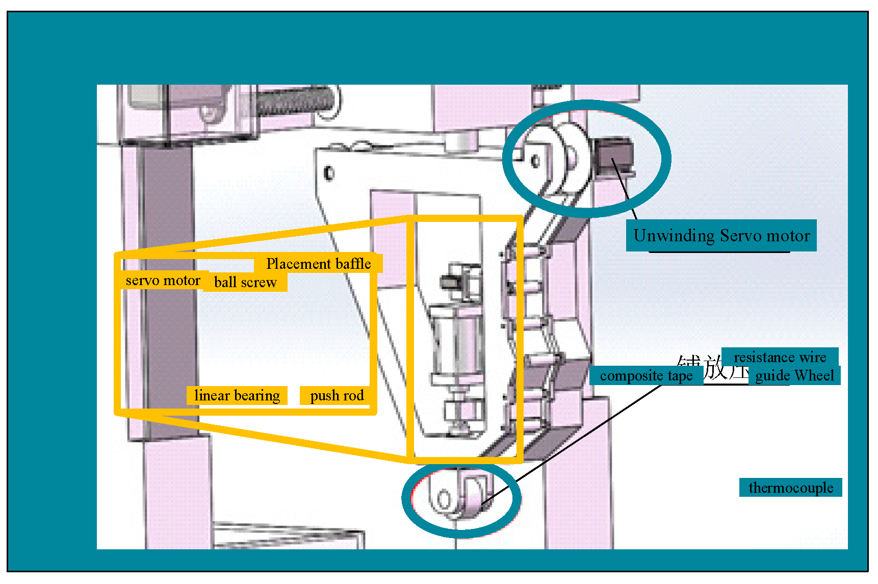
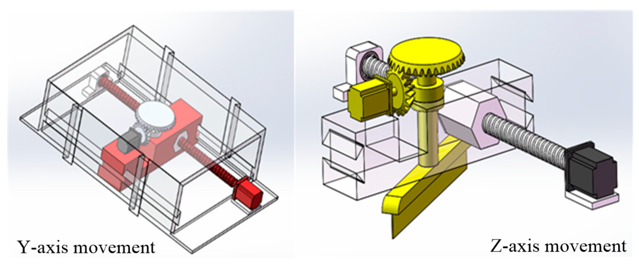
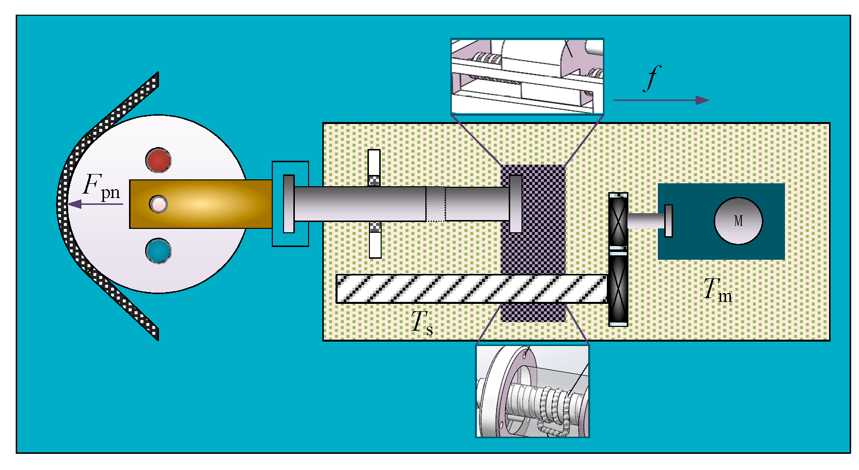
2. Calculation Model of Placement Pressure
3. Establishing Mathematical Model of Placement Pressure Control System
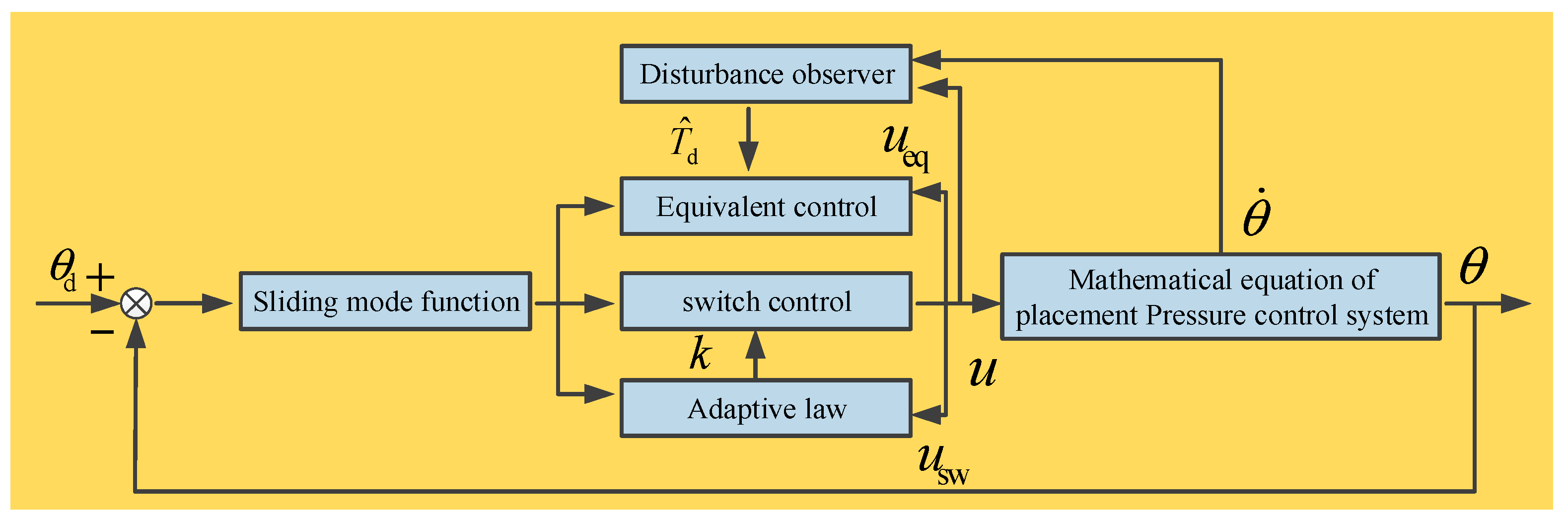
4. DOB-Based ASMC
4.1. Design of Sliding Mode Controller
4.2. Design of Disturbance Observer
4.3. Design of Gain Adaptive Law
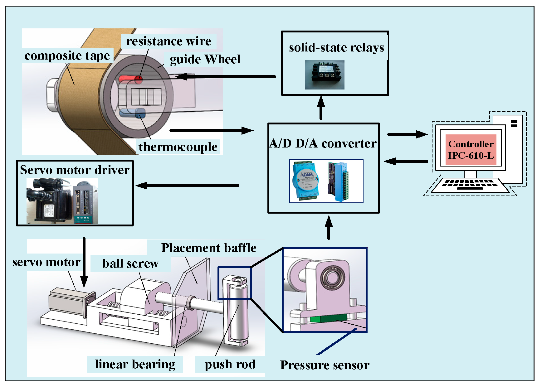
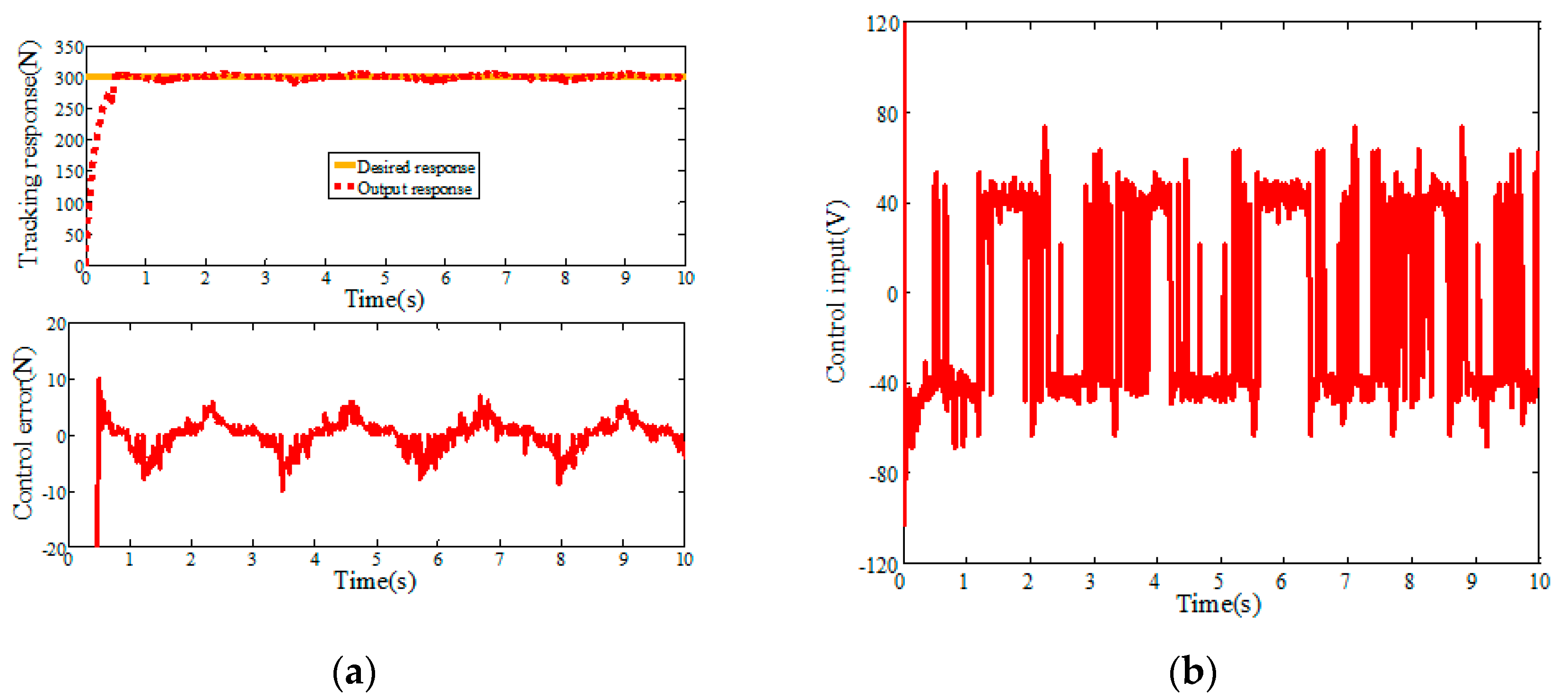
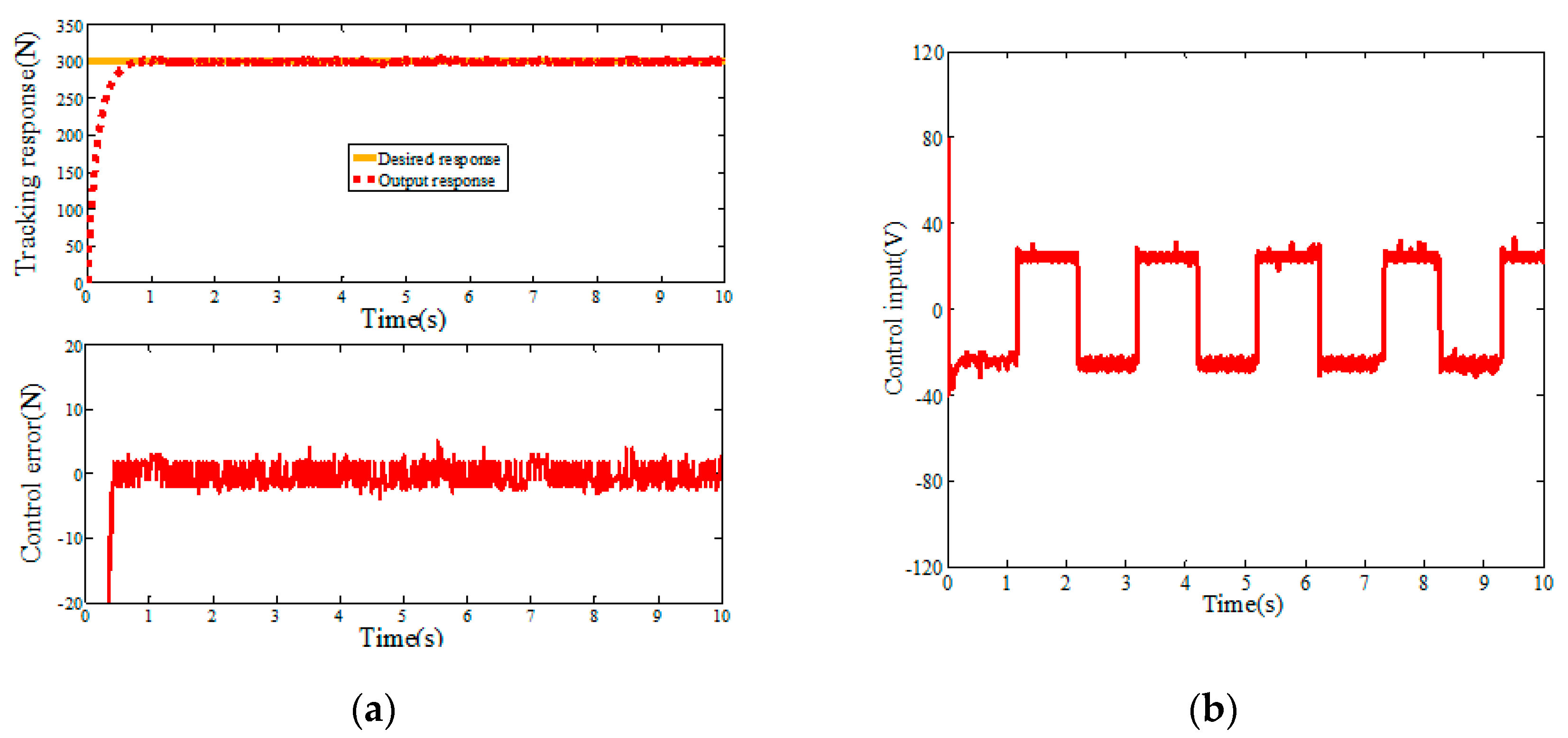
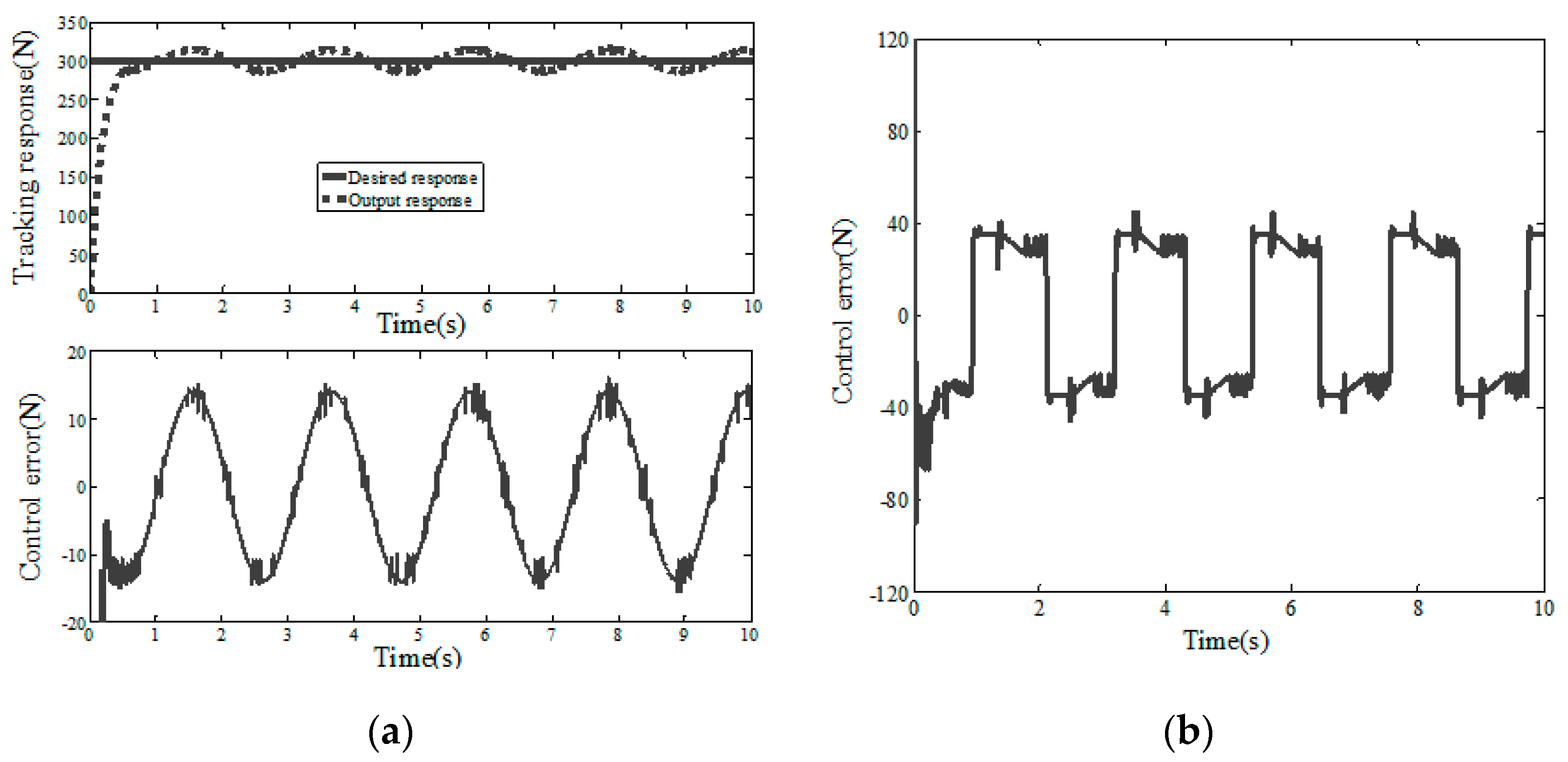
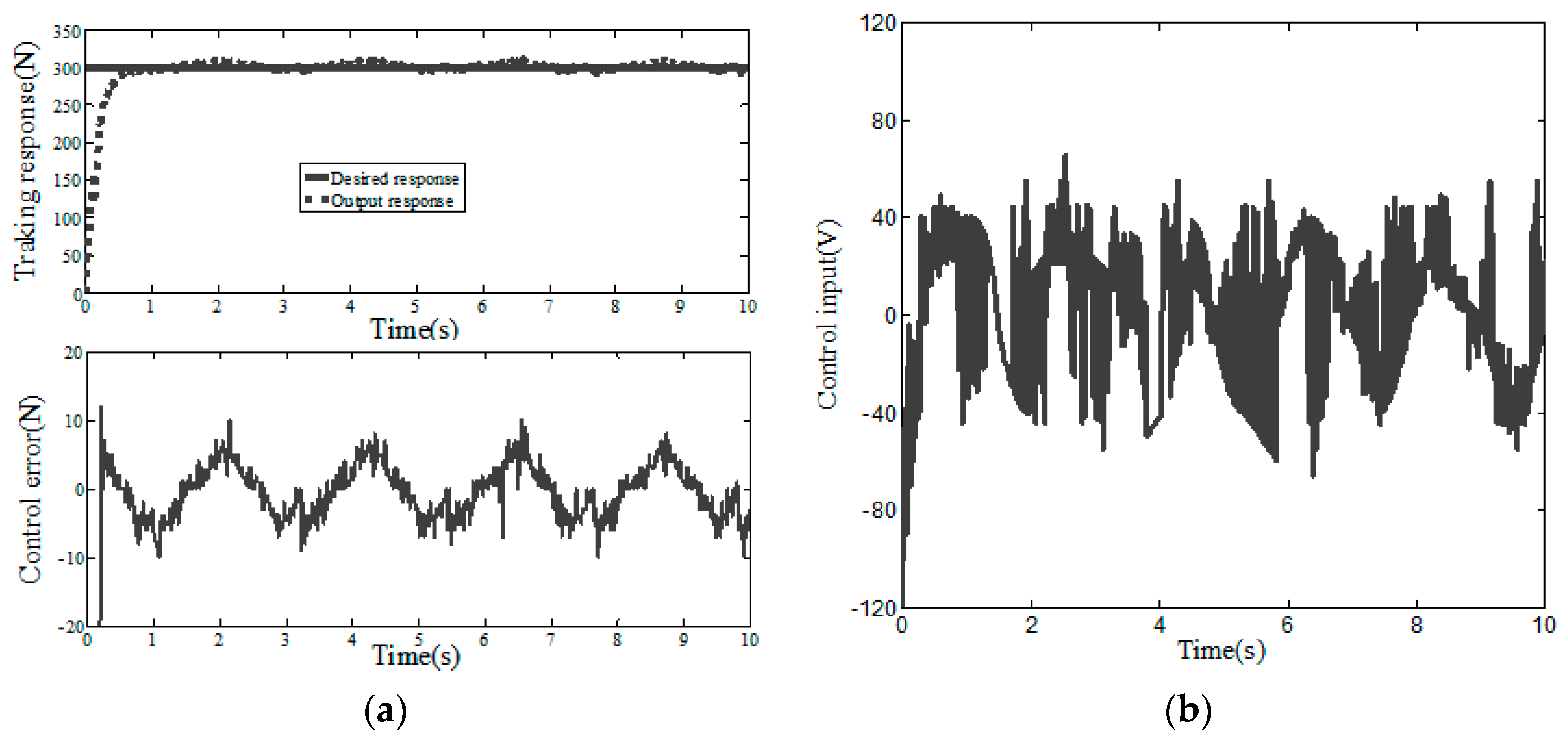
5. Simulation Analysis and Experimental Verification
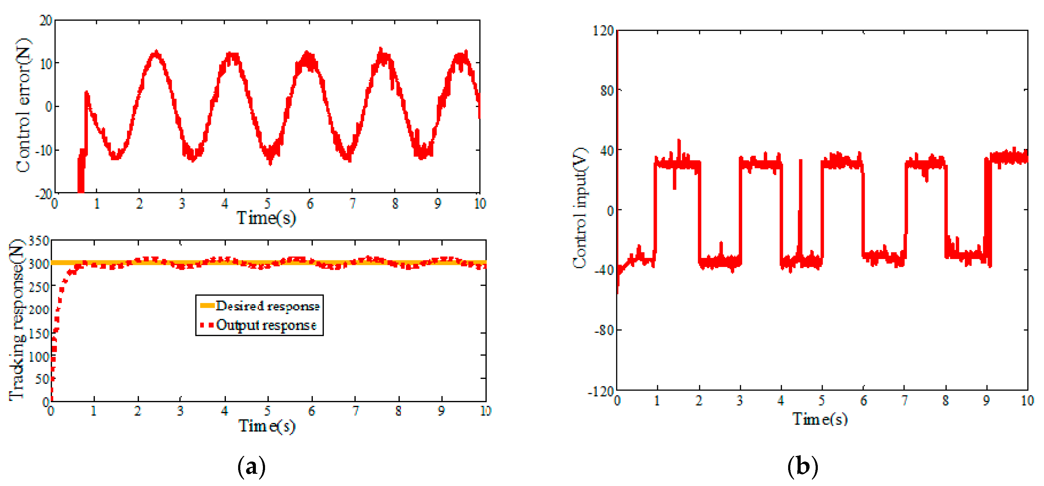
5.1. Simulation Analysis
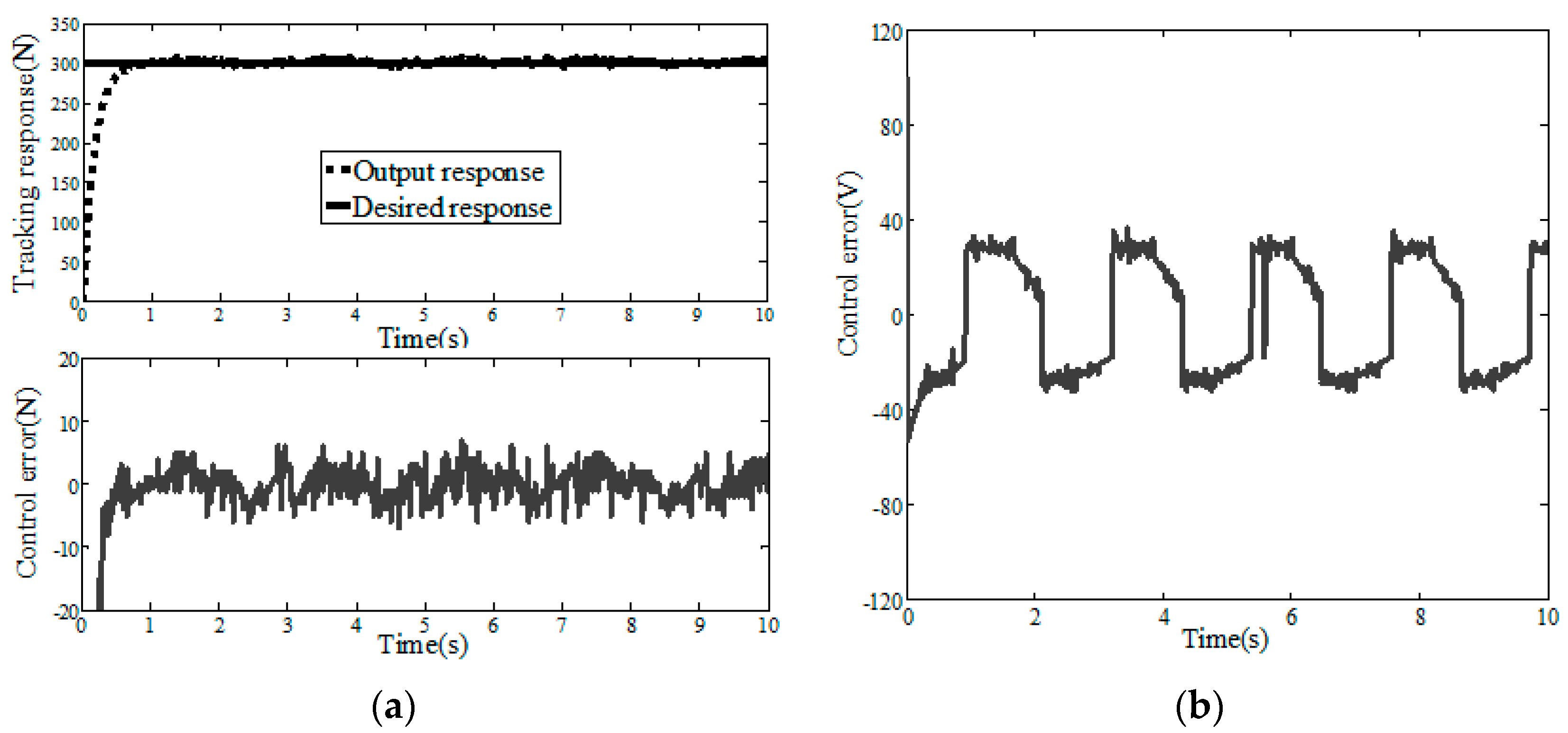
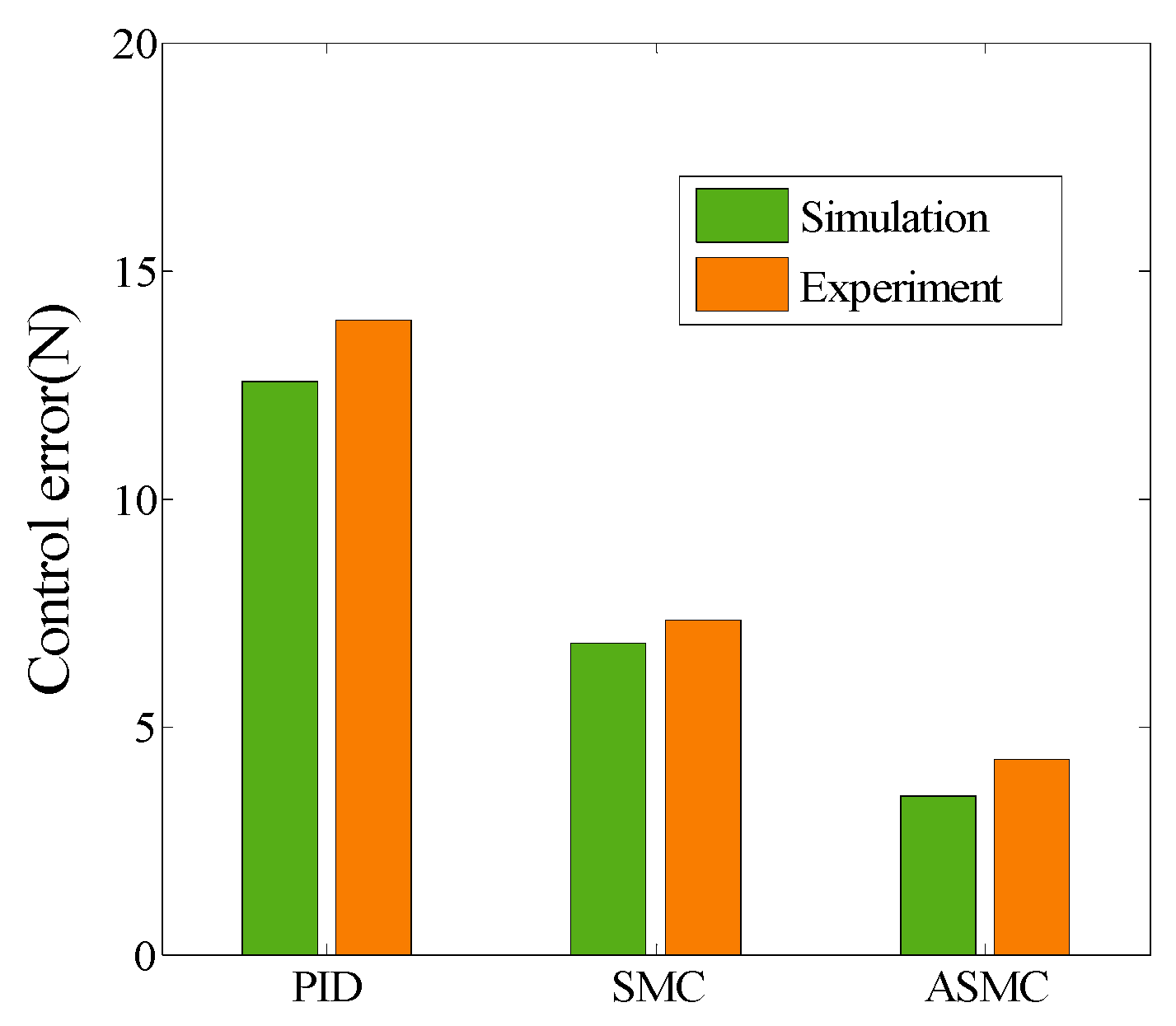
5.2. Experimental Verification
6. Conclusions
Author Contributions
Funding
Conflicts of Interest
References
- Su, J.M.; Zhou, S.J.; Li, R.H.; Xiao, Z.C.; Cui, H. A review of carbon car bon composites for engineering applications. New Carbon Mater. 2015, 30, 106–114. [Google Scholar]
- Jalali, M.; Moliere, T.; Michaud, A.; Wuthrich, R. Multidisciplinary characterization of new shield with metallic nanoparticles or composite aircrafts. Compos. Part B Eng. 2013, 50, 309–317. [Google Scholar] [CrossRef]
- Kim, D.; Centea, T.; Nutt, S.R. Out-time effects on cure kinetics and viscosity for an out of autoclave prepreg Modelling and monitoring. Compos. Sci. Technol. 2014, 100, 63–69. [Google Scholar] [CrossRef]
- Centea, T.; Grunenfelder, L.K.; Nutt, S.R. A review of out of autoclave prepregs—Material properties, process phenomena, and manufacturing considerations. Compos. Part A Appl. Sci. Manuf. 2015, 70, 132–154. [Google Scholar] [CrossRef]
- Deng, B.; Shi, Y.Y.; Yu, T.; Kang, C.; Zhao, P.B. Multi-response parameter interval sensitivity and optimization for the composite tape winding process. Materials 2018, 11, 220. [Google Scholar] [CrossRef]
- Tobalina-Baldeon, D.; Sanz-Adan, F.; Martinez-Calvo, M.A.; Santamaría-Pena, J. Dynamic tensile stress-compressive stress behavior of thermoplastic matrix composite materials reinforced with continuous fiber for automotive damping and anti-vibration structural elements. Materials 2020, 13, 5. [Google Scholar] [CrossRef]
- Lee, E.; Cho, C.H.; Hwang, S.H.; Kim, M.G.; Han, J.W.; Lee, H.; Lee, J.H. Improving the vertical thermal conductivity of carbon fiber-reinforced epoxy composites by forming layer-by-layer contact of inorganic crystal. Materials 2019, 12, 3092. [Google Scholar] [CrossRef]
- Deng, B.; Shi, Y.Y. Modeling and optimizing the composite prepreg tape winding process based on grey relational analysis coupled with BP neural network and bat algorithm. Nanoscale Res. Lett. 2019, 14. [Google Scholar] [CrossRef]
- Kang, C.; Shi, Y.Y.; He, X.D.; Yu, T.; Deng, B.; Zhang, H.J.; Sun, P.C.; Zhang, W.B. Multi-response optimization of T300/epoxy prepreg tape-wound cylinder by grey relational analysis coupled with the response surface method. Mater. Res. Express 2017, 4. [Google Scholar] [CrossRef]
- Yu, T.; Shi, Y.Y.; He, X.D.; Kang, C.; Deng, B.; Song, S.B. Optimization of parameter ranges for composite tape winding process based on sensitivity analysis. Appl. Compos. Mater. 2017, 24, 821–836. [Google Scholar] [CrossRef]
- Simorgh, A.; Razminia, A.; Shiryaev, V.I. System identification and control design of a nonlinear continuously stirred tank reactor. Math. Comput. Simul. 2020, 173, 16–31. [Google Scholar] [CrossRef]
- Pereira, R.D.O.; Veronesi, M.; Visioli, A.; Normey-Rico, J.E.; Torrico, B.C. Implementation and test of a new autotuning method for PID controllers of TITO processes. Control Eng. Pract. 2017, 58, 171–185. [Google Scholar] [CrossRef]
- Karami, M.; Tavakolpour-Saleh, A.R.; Norouzi, A. Optimal nonlinear PID control of a micro-robot equipped with vibratory actuator using ant colony algorithm: Simulation and experiment. J. Intell. Robot. Syst. 2020. [Google Scholar] [CrossRef]
- Weng, Y.P.; Gao, X.W. Data-driven sliding mode control of unknown MIMO nonlinear discrete-time systems with moving PID sliding surface. J. Frankl. Inst. Eng. Appl. Math. 2017, 354, 6463–6502. [Google Scholar] [CrossRef]
- Sharifi, S.; Ahmadyan, S.; Ebrahimi, S. Designing of incorporating fuzzy-sliding mode controller based on strategy moving sliding surface for two-link robot manipulator. J. Frankl. Inst. Eng. Appl. Math. 2012, 9, 3475–3480. [Google Scholar]
- Boiko, I.M. Chattering in sliding mode control systems with boundary layer approximation ofdiscontinuous control. Int. J. Syst. Sci. 2013, 44, 1–8. [Google Scholar] [CrossRef]
- Shtessel, Y.; Edwards, C.; Fridman, L.; Levant, A. Sliding Mode Control and Observation; Springer: New York, NY, USA, 2014; pp. 163–166. [Google Scholar]
- El-Sousy, F.F.M. Adaptive dynamic sliding-mode control system using recurrent RBFN for high-performance induction motor servo drive. IEEE Trans. Ind. Inform. 2013, 9, 1922–1936. [Google Scholar] [CrossRef]
- Velasco, J.; Barambones, O.; Calvo, I.; Zubia, J.; de Ocariz, I.S.; Chouza, A. Sliding mode control with dynamical correction for time-delay piezoelectric actuator systems. Materials 2020, 13, 132. [Google Scholar] [CrossRef]
- Paolo, M.; Nils, W.; Udo, B.; Horst, H. A robust sliding mode control of a hybrid hydraulic piezo actuator for camless internal combustion engines. In Proceedings of the 2011 IEEE/ASME International Conference on Advanced Intelligent Mechatronics (AIM), Budapest, Hungary, 3–7 July 2011; pp. 499–504. [Google Scholar]
- Zhao, Y.; Qiao, W.; Wu, L. An adaptive quasi-sliding-mode rotor position observerbased sensorless control for interior permanent magnet synchronous machines. IEEE Trans. Power Electron. 2013, 28, 5618–5629. [Google Scholar] [CrossRef]
- Huang, C.F.; Liao, T.L.; Chen, C.Y.; Yan, J.J. The design of quasi-sliding mode control for a permanent magnet synchronous motor with unmatched uncertainties. Comput. Math. Appl. 2012, 64, 1036–1043. [Google Scholar] [CrossRef]
- Wang, A.; Jia, X.; Dong, S. A new exponential reaching law of sliding mode control to improve performance of permanent magnet synchronous motor. IEEE Trans. Magn. 2013, 49, 2409–2412. [Google Scholar] [CrossRef]
- Cheng, C.; Liu, S.Y.; Wu, H.Z.; Zhang, Y. Neural network-based direct adaptive robust control of unknown MIMO nonlinear systems using state observer. Int. J. Adapt. Control Signal Process. 2020, 34, 1–14. [Google Scholar] [CrossRef]
- He, J.; Luo, M.Z.; Zhang, Q.Q.; Zhao, J.H.; Xu, L.S. Adaptive fuzzy sliding mode controller with nonlinear observer for redundant manipulators handling varying external force. J. Bionic Eng. 2016, 13, 600–611. [Google Scholar] [CrossRef]
- Wu, H.M.; Karkoub, M. Hierarchical fuzzy sliding-mode adaptive control for the trajectory tracking of differential-driven mobile robots. Int. J. Fuzzy Syst. 2019, 21, 33–49. [Google Scholar] [CrossRef]
- Dong, L.; Tang, W.C. Adaptive backstepping sliding mode control of flexible ball screw drives with time-varying parametric uncertainties and disturbances. ISA Trans. 2014, 53, 110–116. [Google Scholar] [CrossRef]
- Yang, J.; Li, S.H.; Yu, X.H. Sliding-mode control for systems with mismatched uncertainties via a disturbance observer. IEEE Trans. Ind. Electron. 2013, 60. [Google Scholar] [CrossRef]
- Wen, T.; Xiang, B.; Wang, Z.Y.; Zhang, S.L. Speed control of segmented PMLSM based on improved SMC and speed compensation Model. Energies 2020, 13, 981. [Google Scholar] [CrossRef]
- Paciornik, S.; d’Almeida, J. Digital microscopy and image analysis applied to composite materials characterization. ISA Trans. 2010, 15, 172–181. [Google Scholar] [CrossRef]
- Fedulov, B.N.; Antonov, F.K.; Safonov, A.A.; Ushakov, A.E.; Lomov, S.V. Influence of fibre misalignment and voids on composite laminate strength. J. Compos. Mater. 2015, 49, 2887–2896. [Google Scholar] [CrossRef]
- Croft, K.; Lessard, L.; Pasini, D.; Hojjati, M.; Chen, J.H.; Yousefpour, A. Experimental study of the effect of automated fiber placement induced defects on performance of composite laminates. Compos. Part A Appl. Sci. Manuf. 2011, 42, 484–491. [Google Scholar] [CrossRef]
- Okuya, T.; Nakada, M.; Miyano, Y. Reliable test method for tensile strength in longitudinal direction of unidirectional carbon fiber-reinforced plastics. J. Reinf. Plast. Compos. 2013, 32, 1579–1585. [Google Scholar] [CrossRef]
- Deng, B.; Shi, Y.Y. Modeling and simulation of voids in composite tape winding process based on domain superposition technique. Appl. Compos. Mater. 2018, 25, 1219–1236. [Google Scholar] [CrossRef]
- Devanathan, S.; Koch, P.N. Comparison of meta-modeling approaches for optimization. J. Compos. Mater. 2012, 827–835. [Google Scholar] [CrossRef]
- Standardization Administration of the People’s Republic of China. Test Method for Mechanical Properties of Ring of Filament-Winding Reinforced Plastics; Standardization Administration of the People’s Republic of China: Beijing, China, 2008. [Google Scholar]
- Paciornik, S.; D’Almeida, J.R.M. Measurement of void content and distribution in composite materials through digital microscopy. J. Compos. Mater. 2009, 43, 101–112. [Google Scholar] [CrossRef]
- Zhu, H.Y.; Wu, B.C.; Li, D.H.; Zhang, D.X.; Chen, Y.Y. Influence of voids on the tensile performance of carbon/epoxy fabric laminates. J. Mater. Sci. Technol. 2011, 27, 69–73. [Google Scholar] [CrossRef]
- Nikishkov, Y.; Airoldi, L.; Makeev, A. Measurement of voids in composites by X-ray computed tomography. Compos. Sci. Technol. 2013, 89, 89–97. [Google Scholar] [CrossRef]
- Standardization Administration of the People’s Republic of China. Carbon fiber reinforced plastics Determination void content and fiber volume content; Standardization Administration of the People’s Republic of China: Beijing, China, 2008. [Google Scholar]


| Parameter | Value | Description | Parameter | Value | Description |
|---|---|---|---|---|---|
| 7 | Motor resistance | 3 | Pole pairs of motor | ||
| 20 | Magnetic flux | 3 | Pole arc coefficient | ||
| 0.12 | Motor damping coefficient | 0.11 | Screw damping coefficient | ||
| 45° | Dovetail groove slope angle | 0.03 | Motor moment of inertia | ||
| 0.15 | Friction coefficient | 5 | Worktable mass | ||
| 16 | Screw diameter | 8 | Screw lead |
| Response | PID | SMC | ASMC | ||
|---|---|---|---|---|---|
| Step | Simulation | Control error | 12.58 | 6.82 | 3.46 |
| Chattering extent | Small | Large | Smaller | ||
| Experiment | Control error | 13.92 | 7.34 | 4.28 | |
| Chattering extent | Small | Large | Smaller |
| Type | PID | SMC | ASMC |
|---|---|---|---|
| E1 E2 E3 | F1 F2 F3 | G1 G2 G3 | |
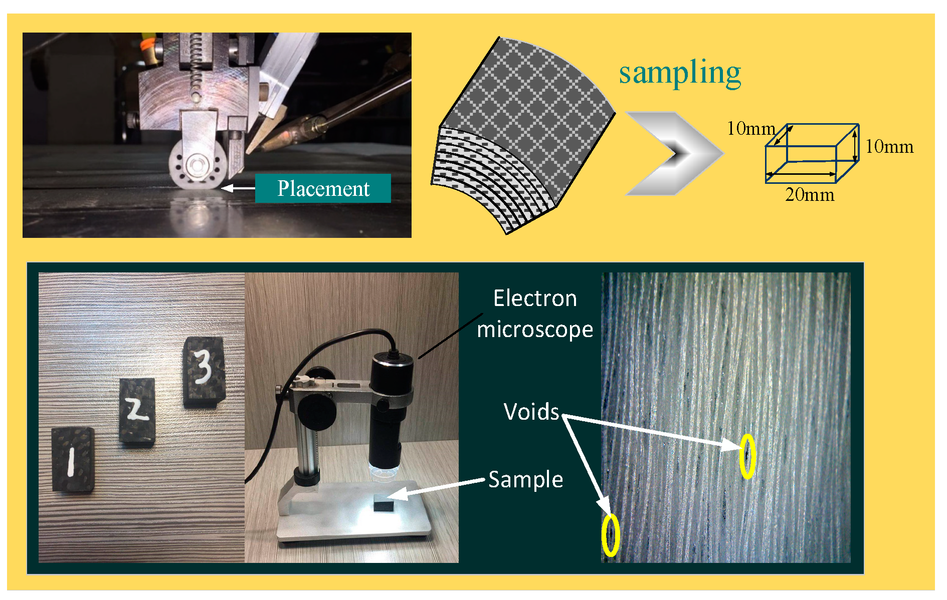
| Void content (%) | 1.2 1.32 1.28 | 0.98 1.02 1.18 | 0.22 0.32 0.38 |
© 2020 by the authors. Licensee MDPI, Basel, Switzerland. This article is an open access article distributed under the terms and conditions of the Creative Commons Attribution (CC BY) license (http://creativecommons.org/licenses/by/4.0/).
Share and Cite
Hong, Q.; Shi, Y.; Chen, Z. Adaptive Sliding Mode Control Based on Disturbance Observer for Placement Pressure Control System. Symmetry 2020, 12, 1057. https://doi.org/10.3390/sym12061057
Hong Q, Shi Y, Chen Z. Adaptive Sliding Mode Control Based on Disturbance Observer for Placement Pressure Control System. Symmetry. 2020; 12(6):1057. https://doi.org/10.3390/sym12061057
Chicago/Turabian StyleHong, Qi, Yaoyao Shi, and Zhen Chen. 2020. "Adaptive Sliding Mode Control Based on Disturbance Observer for Placement Pressure Control System" Symmetry 12, no. 6: 1057. https://doi.org/10.3390/sym12061057
APA StyleHong, Q., Shi, Y., & Chen, Z. (2020). Adaptive Sliding Mode Control Based on Disturbance Observer for Placement Pressure Control System. Symmetry, 12(6), 1057. https://doi.org/10.3390/sym12061057