Abstract
Due to its portability, convenience, and low cost, incompletely closed near-infrared (ICNIR) imaging equipment (mixed light reflection imaging) is used for ultra thin sensor modules and have good application prospects. However, equipment with incompletely closed structure also brings some problems. Some finger vein images are not clear and there are sparse or even missing veins, which results in poor recognition performance. For these poor quality ICNIR images, however, there is additional fingerprint information in the image. The analysis of ICNIR images reveals that the fingerprint and finger vein in a single ICNIR image can be enhanced and separated. We propose a feature-level fusion recognition algorithm using a single ICNIR finger image. Firstly, we propose contrast limited adaptive histogram equalization (CLAHE) and grayscale normalization to enhance fingerprint and finger vein texture, respectively. Then we propose an adaptive radius local binary pattern (ADLBP) feature combined with uniform pattern to extract the features of fingerprint and finger vein. It solves the problem that traditional local binary pattern (LBP) is unable to describe the texture features of different sizes in ICNIR images. Finally, we fuse the feature vectors of ADLBP block histogram for a fingerprint and finger vein, and realize feature-layer fusion recognition by a threshold decision support vector machine (T-SVM). The experimentation results showed that the performance of the proposed algorithm was noticeably better than that of the single model recognition algorithm.
1. Introduction
Fingerprint recognition, face recognition, vein recognition, and other biometric recognition are widely used in financial business, education, social security, and other fields [1,2,3,4,5]. Single biometric recognition often has some defects, such as low universality, low security, easy to be forged, etc. [1,2]. Multi-modal biometric fusion recognition [3,4,5] can effectively overcome these shortcomings.
At present, multi-modal biometric fusion recognition algorithms are mostly based on independent images [6], which are collected through different sensors. Ref. [7] analyzed the advantages and disadvantages of each fusion level and proposed biometrics identification system on the IoMT platform, which combines the face, fingerprint, and finger vein. Tang et al. [8] proposed a multi-sensor data-fusion method based on weighted information entropy. Ref. [9] evaluated the pros and cons of several approaches for the combination of biometric matchers. Angadi and Hatture [10] used the vectors of a palm print and hand geometry with feature-level fusion to represent fusion biometrics. As for fingerprint and finger vein, Yang et al. [11] proposed a fingerprint and finger vein recognition algorithm based on a cancelable multi-biometric system. These methods need to acquire images separately and have strict requirements for acquisition devices, so the application scenario is limited [12]. Kauba et al. [13] proposed a contactless finger and hand vein integrated capturing device and provided the corresponding dataset. The advantages of a contactless capturing device, the principle of imaging which used light transmission and reflected light to acquire palmar finger vein and hand vein images, as well as the hardware structure and light source design are introduced in this paper. Although the design of the capturing device is complex and the device bulky, it provides the possibility of multi-model integrated biometrics equipment and demonstrated its superiority. In this paper, we proposed ultrathin integrated fingerprint and finger vein equipment according to imaging characteristics and principle.
This paper investigates the multi-modal fusion of fingerprint and finger vein. Due to the problems mentioned above, we aim to achieve multi-modal fusion recognition using single finger image. Due to its the portability, convenience, and low cost, we chose the incompletely closed near-infrared (ICNIR) imaging equipment (mixed light reflection imaging) to get a single finger image. Based on our analysis of the ICNIR finger images, it is found that, in addition to the finger vein of infrared light transmission imaging, it also contains some fingerprint information of visible light reflection imaging. Especially for a fuzzy finger with few veins, the fingerprint texture is more abundant. While different from the fingerprint collected by a capacitance sensor and finger vein collected by a completely closed equipment (infrared light transmission imaging), the image quality taken by the ICNIR equipment is poor and the texture is not clear.
For finger vein images taken by ICNIR equipment, traditional recognition algorithms have poor recognition performance due to poor image quality and instability. The Hausdorff distance recognition algorithm [14] is widely used in finger vein recognition. It uses the thinned finger vein image to form the set of feature points and realize recognition. But for finger vein images with few veins and lower imaging quality in ICNIR images, the recognition performance decreases due to the lack of veins. Many researches are based on image features to improve performance, aiming at extracting robust features. Ref. [15] summarized the characteristics of two kind of features, global and local features. Global features can effectively represent the trend of the whole image. It can also reduce the amount of calculation in the subsequent classification through some dimensionality reduction methods, such as principal component analysis (PCA) [16], linear discriminant analysis (LDA) [17], and two directional and two-dimensional principal component analysis ((2D) 2 PCA) [18]. However, the global feature cannot represent the details of the image, which can be affected by exposure, noise, and other problems that are very common in ICNIR images. As for the local feature, more conventional feature coding methods, such as local binary pattern (LBP) and local derivative pattern (LDP) are proposed. Lee et al. [19] combined LBP and LDP to improve the recognition performance. Rosdi et al. [20] proposed an improved coding method called the local line binary pattern (LLBP), which is more in line with the trend of vein. These studies also show that the local detail descriptors feature is more suitable to represent the finger vein structure. Hence, as for the finger vein images taken by ICNIR equipment, we present an adaptive radius LBP (ADLBP) feature using uniform pattern encoding mode to enhance the description ability of vein structure. Finally, the ADLBP combined with support vector machine (SVM) classifier is proposed to improve finger vein recognition performance.
In fingerprint recognition, especially for contactless fingerprint, the quality of an image has a great influence on the accuracy of recognition. Ref. [21] introduced the imaging principle for all kinds of contactless fingerprints, researched on the need to determine the optimum ratio of fingerprint image compression to ensure high accuracy and proposed a compression ratio to achieve the highest recognition accuracy of the system. In addition, as for the contactless fingerprint in an ICNIR image, the background is complex, and the contrast of ridge and valley is not obvious. Therefore, if we want to make full use of this part of the fingerprint we need to find a contactless fingerprint enhancement algorithm. Ref. [22] proposed a Gabor filter based on the local ridge frequency and direction, which is used for image enhancement and overcoming noise in the image. Labati et al. [23] processed the fingerprint images using the Lucy–Richardson algorithm and wiener filter by deconvoluting the image. This algorithm can effectively enhance the contrast of the whole fingerprint and edge details, but it also causes the problem of overly enhancing background noise. Ref. [24] presented a fingerprint segmentation method based on skin color and adaptive threshold points which effectively enhance the ridge structure and extract the thinned image of the fingerprint. The above three algorithms are contactless fingerprint images with a high resolution. The background noise is less and the contrast of ridge is relatively obvious. However, in this paper, the fingerprint in the ICNIR images is shallow and interfered by the background noise and finger vein, making it difficult to separate and enhance the fingerprint by the above algorithms. So we present a contactless fingerprint enhancement algorithm using contrast limited adaptive histogram equalization (CLAHE) for the ICNIR image in this paper. This method effectively separates the fingerprint and enhances the ridge structure from the ICNIR image which provides the image basis for the improvement of recognition performance. In addition, since the ridge structure of the fingerprint in the ICNIR image is unstable, the recognition performance of the existing fingerprint recognitions are poor. Ref. [25] used the transformation parameter clustering and feature point to realize fingerprint recognitions, which cannot adapt to the instability of feature point in the ICNIR image. Manickam et al. [26] proposed a score level based on latent fingerprint enhancement and matching using the Scale-invariant feature transform (SIFT) feature. But the ICNIR image in this paper cannot be enhanced directly by the Gabor filter and the SIFT feature is difficult to be extracted effectively. In addition, some scholars proposed a series of fingerprint features except feature points for recognition. Xu et al. [27] introduced pores spatial relations into fingerprint image comparison with a root-SIFT descriptor and the Hough transform to improve recognition accuracy. This method is aimed at a high resolution fingerprint image taken by capacitance sensors. Ref. [28] presented fingerprint alignment using special ridges. However, it is difficult to find a stable special ridges in ICNIR images. Due to the low quality of the fingerprint, ADLBP is also used in this part, which is convenient for feature-layer fusion with a finger vein, improving recognition performance.
In addition to some conventional image matching methods, with the rapid development of deep learning, some algorithms also show remarkable capabilities in biometrics. Ref. [29] developed a convolutional neural networks (CNN)-based framwork to train a multi-Siamese CNN. The algorithm performed well in a large number of fingerprint training and test data sets. Yang et al. [30] proposed a finger vein representation using generative adversarial networks (FV-GAN) for feature extraction and identification of the finger vein based on GAN. Ref. [12] presented a finger vein and finger shape multi-modal biometrics based on CNN. However, the CNN-based methods will increase the processing time and the capability of CNN for feature representation is affected by the image quality for training, especially for a vein-break image [30] and will cause overfitting problems with small dataset samples. In this paper, the finger images are relatively fuzzy and the image samples collected are not sufficient. Therefore, we consider a SVM algorithm which performs better for small samples and achieves good improvement.
We combine fingerprint and finger vein in a single ICNIR image to realize complementary advantages and improve recognition performance. We propose a feature-level fusion recognition algorithm using a single ICNIR image. Firstly, we propose contrast limited adaptive histogram equalization (CLAHE) and grayscale normalization to enhance the fingerprint and finger vein texture separately, which provides the image basis for feature-layer fusion. Then we propose an adjusted adaptively local binary pattern (ADLBP) combined with the uniform pattern. It can be adjusted adaptively according to the texture size of different regions, which adapts to the difference of texture thickness and interval width in fingerprint and finger vein obtained by the ICNIR image. Fingerprint and finger vein are from the same image and they are consistent in the spatial position, so the texture features are well fused to form a unified feature with the ADLBP histogram in the feature-layer. Finally we propose threshold decision support vector machine (T-SVM) to realize recognition. Experimental results show that the proposed algorithm can extract fingerprint and finger vein features from a single ICNIR finger image accurately and evaluate the accuracy and robustness compared with single model and score-layer fusion recognition algorithm.
The reminder of this paper is organized as follows, Section 2 investigates the imaging principle and characteristics. Section 3 proposes the methods of fingerprint and finger vein texture enhancement. Section 4 proposes the adaptive radius LBP combined with uniform pattern. Section 5 proposes the threshold decision support vector machine. The whole feature-layer fusion method and recognition process will be addressed in Section 6. And Section 7 shows and investigates the experimental results. Conclusions will be presented in Section 8.
2. ICNIR Finger Image Analysis
Near-infrared finger imaging usually adopts the way of transmission imaging for some completely closed imaging equipment, which is widely used in many application scenarios. As shown in Figure 1, the near-infrared light can be used to penetrate the fingers, and the transmitted light will be collected by the photosensitive sensor camera for imaging. As we can see this equipment is bulky and inconvenient to carry, so its application scope is limited.
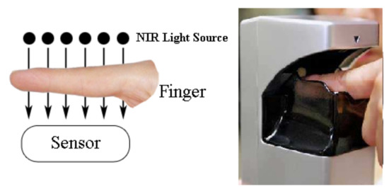
Figure 1.
Transmission imaging and completely closed near-infrared equipment.
As for ICNIR imaging equipment, due to its portability and convenience, they are used for ultra thin sensor module, and have good application prospects. As shown in Figure 2. the module designed by Hangzhou Dianzi University is ultra thin and can be embedded in various portable devices. For equipment with an incompletely closed structure, the near-infrared light source will light the finger from the side, and the visible light will be mixed. As a result, in addition to the reflection imaging of near-infrared light, the reflection imaging information of visible light, such as fingerprints, finger stripes, and so on, can be used to form fusion recognition.
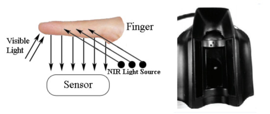
Figure 2.
Reflection imaging and incompletely closed near-infrared equipment.
The basis for fusion recognition of a single ICNIR finger image is that the image collected by the sensor contains both fingerprint and finger vein information. And if we want to collect the information of near-infrared light and visible light reflection imaging in the same picture, we need to select the photosensitive sensing camera to have sensitive sensing effects on near-infrared light and visible light respectively. Then we adjust the near-infrared light intensity and the imaging focal length of the camera to make fingerprint and finger vein imaging better.
We adopted a ov7725 camera sensor based on CMOS technology, and chose the near-infrared light source of 750 nm and adjusted the near-infrared light intensity. The camera imaging focal length was adjusted and a certain amount of visible light was allowed to mix in, so that the reflection of fingerprint and finger vein could captured well. The final ICNIR finger image and the partial enlarged image is shown in Figure 3a,b. It can be found that the image contains not only the finger vein but also the relatively shallow fingerprint information. Through analysis, the following characteristics are observed:
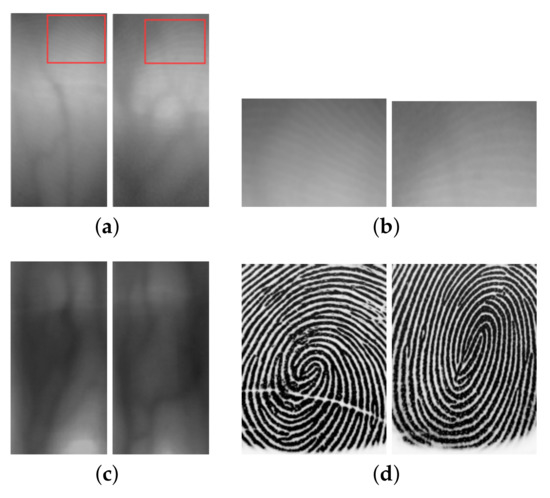
Figure 3.
Comparison of fingerprint and finger vein with different equipment: (a) Incompletely closed near-infrared (ICNIR) finger image; (b) fingerprint partial enlarged of (a); (c) completely closed finger vein image; and (d) capacitance sensor fingerprint.
(i) The width of the veins is wider than that of the fingerprints. The gray level of the pixels at the border of the veins are different. The gradient at the border of the veins is larger;
(ii) The gray distribution range of finger vein and fingerprint is different. The gray value of finger vein pixel is smaller, and the gray value of the fingerprint pixel is larger;
(iii) In the regions with less distribution of finger veins, fingerprint texture is more obvious. Especially for fingers with few veins or poor quality of transmission imaging, fingerprint texture information is more abundant;
(iv) Although it is convenient and portable to collect images by using ICNIR equipment. As shown in Figure 3a,c, compared with completely closed equipment, some finger veins are sparse and not obvious, and some finger veins are even missing;
(v) As shown in Figure 3b,d, different from the fingerprint collected by the capacitance sensor, the fingerprint in ICNIR finger image is very shallow, and the intervals between ridges are different.
According to the above analysis of the imaging principle and imaging characteristics of near-infrared finger image taken by the ICNIR equipment, it is considered that the fingerprint texture and finger vein texture can be separately enhanced from a single image due to its diversity.
Section 1 and Section 2 summarizes the characteristics of different equipment. As shown in Table 1, capacitance fingerprint equipment has high portability, but the recognition accuracy is medium. Additionally, although the near infrared (NIR) finger vein equipment can be used to collect high quality images, and good recognition accuracy can be obtained by using these images, the cost of equipment is high and it is inconvenient to carry. The ICNIR finger equipment in this paper takes the advantages of both. This equipment not only takes into account the high portability and low cost, but also improves the recognition performance by using multi-modal fusion recognition.

Table 1.
Comparison of characteristics of different equipment.
3. Fingerprint and Finger Vein Texture Enhancement
According to the analysis of the above image characteristics, the feasibility of finger vein fusion recognition with a single finger image taken by ICNIR equipment is proved. However, because of the particularity of imaging caused by incompletely closed equipment, the fingerprint texture in the image is not obvious, which is difficult to fully utilize. Besides, the fingerprint and finger vein in the same image will interfere with each other, so it is necessary to enhance the fingerprint texture and finger vein texture separately. In this section, a fingerprint enhancement algorithm based on CLAHE is proposed, and we also introduce the grayscale normalization to enhance the finger vein. It provides the basis of images for subsequent fusion recognition.
3.1. Fingerprint Texture Enhancement Based on CLAHE
In the single finger image taken by ICNIR equipment, because the contrast difference of fingerprint ridge is not obvious in some visible light reflection imaging, information on the fingerprint ridge cannot be highlighted, so it is difficult to make full use of it. Compared with the finger vein, the pixel gray of fingerprint ridges is larger than the surrounding background information, and each ridge occupies a smaller pixel width, so we use CLAHE [31] to enhance the fingerprint texture.
As shown in Figure 4, by limiting the height of local histogram, the enhancement amplitude of local contrast is limited, so that noise amplification and excessive enhancement of local contrast is limited. Through CLAHE, the local contrast can be enhanced, and the fingerprint ridge texture of the fingerprint can also be enhanced at the same time. Firstly, the image is divided into several sub blocks, and each sub block histogram is cut and equalized. Then each pixel is reconstructed by interpolation.
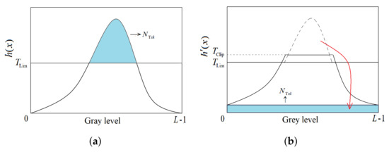
Figure 4.
Schematic diagram of the contrast limited adaptive histogram equalization (CLAHE) algorithm: (a) Histogram clipping and (b) histogram after CLAHE allocation.
The implementation of the CLAHE algorithm is as follows:
(i) The image is divided into non overlapping sub blocks with pixels, the smaller the sub block is, the more obvious the contrast of local details will be;
(ii) Count the histogram distribution of each sub block , where the gray level range is , and the max value is L;
(iii) Calculate the clipping threshold of each sub block:
where is the normalized clipping coefficient, and the value range is ;
(iv) Pixel allocation. According to the clipping threshold calculated in Equation (1), the histogram of each sub block is clipped, the total number of pixels exceeding the threshold is counted, and the average pixel needed to be increased for each gray level is calculated: . Finally, the distribution threshold is obtained: , and the histogram after reallocation is as follows:
(v) Block equalization of histogram obtained in Equation (2);
(vi) The bilinear interpolation method [32] is used to reconstruct the gray value of each central pixel.
The size of the image processed in this paper is 400 × 200. The normalized clipping coefficient is 0.05, and the sub block pixels are 8 × 5. The enhancement is shown in Figure 5.

Figure 5.
Comparison of fingerprint equalization enhancement methods: (a) Original image; (b) local enlargement of original image; (c) after CLAHE enhancement; (d) local enlargement after CLAHE; (e) after traditional histogram equalization; and (f) local magnification after traditional histogram equalization.
In Figure 5, the image enhanced by traditional histogram equalization is shown in Figure 5e,f, and the overall contrast difference is large. So the texture enhancement is not obvious; the image enhanced by CLAHE is shown in Figure 5b,c. The texture and local contrast are significantly enhanced, and the interference of vein texture is suppressed. Through CLAHE, it not only enhances the fingerprint texture, but also separates the fingerprint from the ICNIR image.
3.2. Grayscale Normalization Refers to Vein Enhancement
Due to the instability of imaging caused by ICNIR equipment, the gray range of finger veins is inconsistent, and the gray contrast of some regions is not obvious. Grayscale normalization [33] highlights the texture information in the image by enhancing the regional contrast. We used the linear grayscale normalization algorithm to pull up the grayscale value to . In this way, the gray-scale distribution of each region of the image is uniform, and the image can be enhanced without losing the details. The principle is shown in Equation (3):
In the equation, is the gray value after grayscale normalization; is the gray value before grayscale normalization; and max and min are the minimum and maximum value of the image grayscale before normalization, .
As shown in the Figure 6, after the normalization, the gray level of the vein region in the image is lower than the surrounding background region, the overall contrast is enhanced, and the vein texture is more clear.
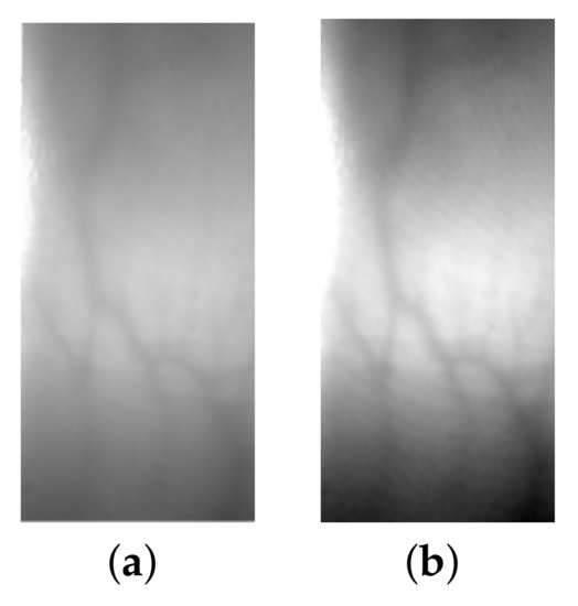
Figure 6.
Schematic diagram of grayscale normalization: (a) Original image and (b) after grayscale normalization.
4. Adaptive Radius LBP Combined with Uniform Pattern
LBP [34] is a global feature that describes the texture of an image. It makes full use of the information of the whole image and can form a unified standard dimension feature, which can effectively solve the difficulty of feature fusion. However, due to the particularity of imaging caused by ICNIR equipment, the width and thickness of texture interval are different. The original LBP feature operator is a fixed size, which cannot accurately represent the texture information of different sizes in the image. Therefore, in this section, we propose the adaptive radius LBP (ADLBP) combined with a uniform pattern, which can adaptively adjust the radius of LBP operator according to the texture size of different regions of the image. It can also adapt to the texture thickness and the difference of interval width, and reduce the dimension with the uniform pattern, to some extent, reduce the noise redundancy information.
As described in Section 2, in contrast to high-quality imaging finger vein images taken by completely closed near-infrared equipment, the quality of the finger vein in ICNIR images is poor. As shown in Figure 7a, different fingers or different regions of the same finger have great differences in the width and thickness. Also, in contrast to the fingerprint collected by the capacitance sensor, the fingerprint in ICNIR finger images are different. As shown in Figure 7b, the fingerprint ridges on the left side of the framed region are wider than those on the right.
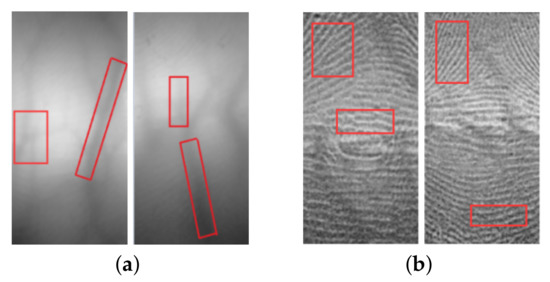
Figure 7.
Texture difference diagram: (a) Finger Vein image and (b) fingerprint image.
The traditional LBP coding method is as follows. In the Equation (4), stands for the central pixel value and denotes the pixel value of the P-neighbor pixels related to the central one:
The region of traditional LBP is a fixed radius, which has limitations when the texture sizes are different. So it is necessary to adjust the LBP processing radius of different regions to adapt to the finger images obtained by ICNIR equipment. The adjustment is mainly based on two principles: Firstly, the small difference of LBP code distance under different radius indicates that the coding value in this region has good consistency. It belongs to the region with small size and gentle texture in the image. The LBP code with a small radius is used to describe the details more accurately, then if the difference is great, it indicates that the small radius cannot cover the entire width of the stripe, or that the region is seriously disturbed by noise and the small radius coding value is not accurate. So we use a large radius to repair it. Based on this, an adaptive multi-level processing radius LBP coding method is adopted, and the specific correction method is as follows:
(i) Respectively calculate the encoded value of the image when the radius is 1, 2, and 3: , , and ;
(ii) For each pixel in the image, we compare the LBP coding values under different radius. As shown in Equation (6), the coding values with the processing radius of 2 and 3 are compared. In the equation, represents the binary code distance between a and b. If the code distance is less than or equal to 3, the coding value between different radius are consistent. The result of the small radius is adopted as the coding value. If the code distance is more than 3, it is modified with the result of a large radius. So we obtain the intermediate process coding value after the first modification:
(iii) As shown in Equation (7), we compare the code distance between intermediate process coding value in step (ii) and the coding value . The rules are same as those in step (ii), and the LBP code result after the final multi-level processing radius correction is obtained.
After the above adjustment, the multi-level adaptive LBP coding not only retains the details of the edge of the image, but also reduce and suppress the impact of noise. So it can be used to represent the texture information of different sizes in fingerprint and finger vein separated from a single ICNIR finger image.
In addition, due to the different probability of occurrence for different ADLBP coding values, the coding values with a lower probability is the background region with more noise. For this part of high-frequency redundant information, it should be coded to the same value and the coding mode with higher probability represents the smooth and stable region in the image, which reflects the whole texture information of fingerprint and finger vein. In this region, the number of 0 and 1 jumps in the cyclic 8-bit coding is less than or equal to 2, because the gray value of the pixel is relatively stable and it is not easy to produce mutation. According to this characteristic, LBP uniform pattern [35] defines that the LBP coding mode with the number of hops less than or equal to 2 will be retained and re-coded sequentially. The coding mode with the number of hops greater than 2 is coded to 0. Therefore, for the mode with 8-ADLBP sampling points, it can form a mapping table from 256 to 59 dimensions, and can reduce the dimensions of the ADLBP. The uniform pattern expression is as follows:
In Equation (8), stands for the central pixel value and denotes the pixel value of the P-neighbor pixels related to the central one. If U is less than or equal to 2, it belongs to uniform pattern. And the rest of the ADLBP coding values are set to 0.
Various LBP coding modes of fingerprint and finger vein are shown in Figure 8 and Figure 9. As shown in Figure 8b–d, it can be seen that LBP operators with a fixed radius cannot obtain the overall trend texture information of a fingerprint. A large number of grain noise is introduced in Figure 8b, and the texture in Figure 8c,d are more clear. Furthermore, as shown in Figure 9b, the texture in the middle of vein and in the background is disordered. In Figure 9c,d, the ADLBP and ADLBP combined with a uniform pattern are used to remove the noise while retaining the edge details, which makes the whole texture more continuous, smooth, and clear.
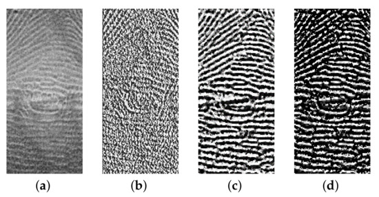
Figure 8.
The comparison diagram of fingerprint local binary pattern (LBP) coding mode: (a) Fingerprint enhancement; (b) original LBP; (c) adaptive radius LBP (ADLBP); and (d) ADLBP with uniform pattern.
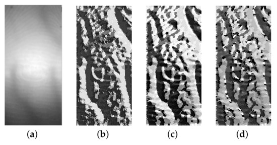
Figure 9.
The comparison diagram of Finger vein LBP coding mode: (a) Finger vein enhancement; (b) original LBP; (c) ADLBP; and (d) ADLBP with an uniform pattern.
5. Threshold Decision Support Vector Machine
Multi-class classification of support vector machines (SVM) [36] is realized by the superposition of two kinds of classifiers. When k-class registered samples are input, SVM trains all k-class registered samples through the binary classifiers, and the number of the binary classifiers for k-class is k(k − 1)/2. The samples to be matched are classified through all binary classifiers. Finally, we vote for k categories, and the number of votes is counted. The category with the most votes is the matching result.
However, for this kind of traditional SVM, it is impossible to judge the case that the samples to be classified do not belong to the classes contained in the database. This is because when the samples to be classified do not belong to the database, the SVM multi-classifier will still classify them into one of the classes contained in the database according to the classification rules. In this case, the false recognition rate of out of class samples is 100%. In order to solve this problem, it is necessary to adjust the final classification decision rule and select the out-of-class samples, so the threshold decision SVM (T-SVM) is introduced.
The samples that are out-of-class can be regarded as the same degree of similarity with all k-fingers in the database. The difference between the matching scores obtained by k(k − 1)/2 classifiers is little. For in-class samples, there are several items with higher matching scores in k(k− 1)/2 results. According to this characteristic, most of the invalid matching results can be eliminated by setting a threshold. The detailed steps are as follows:
(i) Through all k(k − 1)/2 binary classifiers, calculate the matching scores of the samples to be matched;
(ii) Because the value range of the matching scores is not fixed and changes with the samples to be matched, the threshold can be determined according to the maximum matching score under the matching result. The results which below the threshold can be eliminated, as shown in Equation (9):
In the equation, is the matching score between the sample to be matched and the ith classifier. indicates whether the matching result is valid or not. is the maximum matching score when the sample through all k(k − 1)/2 binary classifiers; and is the threshold;
(iii) By selecting out the valid matching results through Equation (9), we can make the distribution of the final voting results more centralized, rather than the random and average distribution of voting results of the samples. However, if the category with the highest number of votes is still used as the classification result, the above error recognition will still occur. It is necessary to make a decision rule on the final voting result. So the decision rule about whether to accept the sample or not is shown in Equation (10):
where represents the maximum number of votes in the voting results of k-type fingers. represents the submaximum number of votes and and are thresholds.
Equation (10) indicates that only when the maximum number of votes exceeds threshold and also exceeds the submaximum value after multiplying with the threshold , the sample is classified to the category with maximum number of votes. If the maximum value and the submaximum value are close to each other, it indicates that the classification difference between two categories is little, and it is difficult for the classifier to give the definite classification result. So the sample is rejected.
By adjusting the value and , we can obtain the false rejection rate (FRR) performance at different false accept rate (FAR) levels.
6. Fingerprint and Finger Vein Feature Layer Fusion Recognition
Feature-layer fusion [37,38] is a multi-modal fusion method, which utilizes and integrates various information more effectively. And if one of the biometric systems is poor in performance, it will overly affect the overall recognition performance in score-layer fusion [39]. By integrating all information into a completely new feature, feature-layer fusion can solve this problem and realize complementary advantages. In addition, the fingerprint and finger vein are from the same image, and the spatial position is one-to-one correspondence. In this way, feature-layer will has the advantage of good compatibility. Therefore, compared with the fusion recognition of images collected by different sensors of independent images, the ICNIR finger images in this paper are more suitable for feature-layer fusion.
The implementation of parallel feature fusion [38,40] is given below: Let and respectively represent fingerprint and finger vein feature spaces of n-dimension and m-dimension. Where x and y respectively represent the vectors of two samples belonging to the feature space, and it can be expressed as and . After fusion, the new feature vector is , and the feature dimension becomes dimension. Parallel feature fusion also has disadvantages. When the dimensions of two feature vectors to be fused are different, one of the features with lower dimensions needs zero-padding, so spurious features will be introduced. In this paper, the fingerprint and finger vein feature were extracted from the same ICNIR finger image. The feature dimension extracted by the ADLBP combined with the uniform pattern was same, so the problem of introducing the spurious feature was avoided.
The ADLBP combined with the uniform pattern of fingerprint and finger vein are shown in Figure 10. The LBP-feature of fingerprint and finger vein texture are divided into rectangular blocks. We made histogram statistics for each sub-block and the feature vector with -dimensions were formed. Through parallel feature fusion, the feature vectors of two models from same single ICNIR image were fused before we finally proposed T-SVM to classify the fusion vectors.

Figure 10.
LBP histogram extraction of fingerprint and finger vein: (a) LBP histogram extraction of finger vein and (b) LBP histogram extraction of the fingerprint.
The realization process of fingerprint and vein feature-layer fusion recognition algorithm for single ICNIR image is shown in Figure 11:
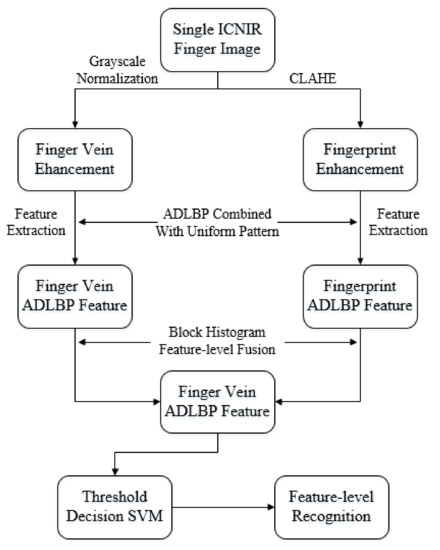
Figure 11.
Feature-layer fusion recognition diagram of fingerprint and finger vein.
(i) As for ICNIR finger image, according to the fingerprint and finger vein image enhancement algorithm proposed in the Section 3, the enhanced fingerprint and finger vein image was extracted from the original image;
(ii) We used ADLBP combined with the uniform pattern to extract the feature of fingerprint and finger. Then we collected the feature vectors of the LBP block histogram for fingerprint and finger vein models;
(iii) We realized feature-layer fusion by adopting the method of parallel feature fusion;
(iv) According to the category label for training set, k(k − 1)/2 T-SVM binary classifiers are trained. Finally, we realized the matching classification recognition for the test set.
7. Materials and Experimental Results
The images of this experiment consist of 300 kinds of finger images collected by the ICNIR equipment designed by Hangzhou Dianzi University, which contains different kinds of finger images for volunteers of different ages. Every kind of finger contains 15 images, and the image is 400 × 200. We divided the image into two categories: 300 × 10 training set and 300 × 5 test set. Besides, 100 kinds of finger images with low imaging quality (100 × 10 training set and 100 × 5 test set) were selected to form a low-quality finger image database. We used translation and cropping to conduct data augmentation, expending five times to establish two new databases. The data-augmentation process was conducted only for training data. For the testing data, non-augmented original images were used. The experimental simulation was carried out in the libsvm toolbox of MATLAB r2014a.
We used CHAHE and grayscale normalization algorithm to enhance the fingerprint and finger vein of training sets. Then we extracted the ADLBP features combined with uniform pattern respectively and realized feature-layer fusion by adopting the method of parallel feature fusion. We chose RBF radial basis kernel as the kernel function of T-SVM and 7-3 cross-validation was used for training verification [36]. Then the classifiers of T-SVM was trained by feature vectors and the labels of a training set. By traversing the penalty factors c and the parameter of the kernel function g within limits, the best parameter for the T-SVM was obtained (the penalty and the kernel function parameter ). Finally, the same image processing, feature extraction, and fusion process were carried out for the test set and we adjusted and to obtain recognition performance under different FRR and FAR levels.
7.1. The Performance Analysis of Fusion Recognition for ADLBP Combined with Uniform Pattern
According to the threshold decision SVM proposed in Section 5, we set and adjusted the threshould and to obtain recognition performance under different FRR and FAR levels. Then we used the receiver operating characteristic (ROC) curve to evaluate the performance. As shown in Figure 12 and Figure 13, the recognition performance of various algorithms under the 300-finger ICNIR images (and data augmentation) database are compared.
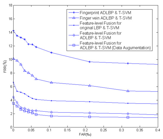
Figure 12.
Receiver operating characteristic (ROC) curve of different algorithms for 300-finger images database.
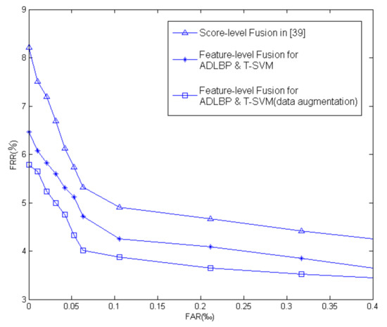
Figure 13.
ROC curve of different layer for low quality 100-fingers database.
In some application scopes such as locks and financial payments, we often need to ensure a low FAR level. So we used the FRR rate when FAR was 0 (that is, the intersection of ROC curve and longitudinal axis) to compare the performance of each algorithm. We also used equal error rate (EER) (that is when FAR = FRR = EER) to evaluate the performance of the algorithm. As the deference of magnitude between FAR and FRR in Figure 12 and Figure 13 are large, the EER lines cannot be reflected in the figures. Therefore we give the EER results directly based on the data.
We compared the ROC curves of the single model (ADLBP combined with uniform pattern for fingerprint and finger vein) and feature-level fusion recognition algorithm (original LBP and ADLBP). It can be seen that when FAR is 0, FRR decreased from 14.25% and 10.11% to 6.67% and 4.40% respectively (EER was 3.52%, 1.33%, 1.09% and 0.98%). In the data augmentation database, FRR decreased to 3.51% (EER was 0.95%). The lower EER rate shows that the recognition algorithm of feature-layer fusion with T-SVM was better than a single model. The performance obviously improved. After the feature-layer fusion, the information of the two models was fully integrated and utilized to improve the recognition performance.
In addition, compared with the results of the original LBP feature-layer fusion and T-SVM and ADLBP combined with uniform pattern feature-layer fusion and T-SVM, the FRR rate decreased from 6.67% to 4.40% (EER was 1.09% and 0.98%). It shows that the ADLBP combined with uniform pattern could describe the texture of different modes and different sizes in single ICNIR finger image better. The random background information and high frequency redundant noise could also be reduced by a uniform pattern, which improved recognition performance.
7.2. Performance Analysis of Different Fusion Levels for Low Quality Finger Images
A total of 100 low-quality finger images were selected from 300 fingers database to calculate the hausdorff distance [13], matching scores for fingerprint and finger vein separately. Then we combined the matching scores based on normalization and weighting techniques [39] to realize score-layer fusion. We compared the performance of score-layer and feature-layer fusion. It was verified that for some finger images with poor imaging quality, feature-layer fusion recognition had a better performance. ROC curve is shown in Figure 13.
The ROC curve of score-layer fusion and ADLBP combined with uniform pattern feature-layer fusion and T-SVM classification are compared. The latter was closer to the coordinate axis, which shows that it had better recognition performance. The algorithm proposed in this paper effectively represented the fingerprint and finger vein feature information extracted from the single ICNIR image. It made more effective use of various information and fused them into a complete new feature. It works better than score-layer fusion and improved the recognition performance for low-quality ICNIR finger images. In particular, when FAR was 0, FRR decreased from 8.21% to 6.47% (EER was 1.27% and 1.13%). In the data augmentation database, FRR decreased to 5.78% (EER was 1.02%).
7.3. Performance Comparison between Multimodal Fusion and Single Modal Recognition
In order to further verify the effectiveness of the feature-level fusion recognition algorithm proposed in this paper for single ICNIR finger images, we compared the feature-level fusion recognition algorithm and traditional single model algorithm such as feature-point matching [25] and SIFT feature matching [26] in fingerprint recognition, gradient correlation coefficient [41], and hausdorff distance [14] algorithm in finger vein recognition. As shown in Table 2, the recognition rate of the ADLBP feature-layer fusion and T-SVM recognition algorithm was significantly improved compared with the single model recognition algorithm under under 0% FAR. It verified that the recognition performance of the finger feature-level multi-modal fusion was better than that of the single model.

Table 2.
Comparison of recognition rate for 300-fingers database Obtained by ICNIR equipment under a 0% false accept rate (FAR).
In order to verify that the feature-layer fusion recognition algorithm in this paper could also improve the recognition performance for independent images, we used the public database (SDUMLA-HMT database): 636 finger vein images, 6 images of each finger and 636 finger fingerprint images, 6 images of each finger (FT-2BU capacitance sensor). The result of the simulation is shown in Table 3. The recognition rate improved compared with the single modal recognition algorithm. It also shows that the feature-level fusion recognition algorithm in this paper was also applicable for independent images acquired by different equipment.

Table 3.
Comparison of recognition rate for SDUMLA-HMT database obtained by independent equipment under a 0% FAR.
8. Conclusions
In this paper, we investigated the fingerprint and finger vein feature-layer fusion recognition algorithm based on a single ICNIR finger image. Firstly, the fingerprint and finger vein texture were enhanced using the CLAHE and gray-scale normalization algorithm. From the results, the texture structure of fingerprint and finger vein were enhanced and separated. Secondly, the ADLBP combined with a uniform pattern was proposed to solve problems of limited texture descriptive ability of the original LBP feature for different textures. It also reduced high frequency redundant noise and feature dimension. Then the threshold decision SVM was proposed to solve the problem of 100% false accept rate for out of class samples. The experimental results showed that when FAR was 0, the recognition rate of the proposed algorithm was significantly improved and the EER rate decreased. Therefore the proposed feature-layer fusion recognition algorithm had a better performance than the score-layer method for low quality fingers and had a significant improvement compared with the single modal recognition algorithm.
Author Contributions
Conceptualization and methodology, G.-L.L. and L.S.; software and validation, G.-L.L.; formal analysis, G.-L.L. and L.S.; writing—original draft preparation, G.-L.L.; writing—review and editing, L.S., Y.-D.Y. and H.-X.W.; supervision, L.S., Y.-D.Y. and H.-X.W.; project administration, G.-D.Z.; funding acquisition, L.S. and G.-D.Z. All authors have read and agreed to the published version of the manuscript.
Funding
This research was funded by the open project of Zhejiang Provincial Key Laboratory of Information Processing, Communication and Networking, Zhejiang, China.
Conflicts of Interest
The authors declare no conflict of interest.
References
- Jain, A.K.; Ross, A.; Prabhakar, S. An introduction to biometric recognition. IEEE Trans. Circuits Syst. Video Technol. 2004, 14, 4–20. [Google Scholar] [CrossRef]
- Prabhakar, S.; Pankanti, S.; Jain, A.K. Biometric recognition: Security and privacy concerns. IEEE Secur. Priv. 2003, 1, 33–42. [Google Scholar] [CrossRef]
- Severance, C. Anil Jain: 25 years of biometric recognition. Computer 2015, 48, 8–10. [Google Scholar] [CrossRef][Green Version]
- Zheng, W.S.; Sun, Z.; Wang, Y.; Chen, X.; Yuen, P.C.; Lai, J. Hand Dorsal Vein Recognition Based on Hierarchically Structured Texture and Geometry Features. In Chinese Conference on Biometric Recognition; Lecture Notes in Computer Science; Springer: Berlin/Heidelberg, Germany, 2012; Volume 7701, pp. 157–164. [Google Scholar]
- Martinho-Corbishley, D.; Nixon, M.S.; Carter, J.N. Soft biometric recognition from comparative crowdsourced annotations. In Proceedings of the 6th International Conference on Imaging for Crime Prevention and Detection (ICDP-15), London, UK, 15–17 July 2015; pp. 1–6. [Google Scholar]
- Poria, S.; Cambria, E.; Bajpai, R.; Hussain, A. A review of affective computing: From unimodalanalysis to multimodal fusion. Inf. Fusion 2017, 37, 98–125. [Google Scholar] [CrossRef]
- Xin, Y.; Kong, L.; Liu, Z.; Wang, C.; Zhu, H.; Gao, M.; Zhao, C.; Xu, X. Multimodal Feature-level Fusion for Biometrics Identification System on IoMT Platform. IEEE Access 2018, 6, 21418–21426. [Google Scholar] [CrossRef]
- Tang, Y.C.; Zhou, D.Y.; Xu, S.; He, Z.H. A weighted belief entropy-based uncertainty measure for multi-sensor data fusion. Sensors 2017, 17, 928. [Google Scholar] [CrossRef]
- Lumini, A.; Nanni, L. Overview of the combination of biometricmatchers. Inf. Fusion 2017, 33, 71–85. [Google Scholar] [CrossRef]
- Angadi, S.A.; Hatture, S.M. Biometric person identification system:A multimodal approach employing spectral graph characteristics of hand geometry and palmprint. Int. J. Intell. Syst. Technol. Appl. 2016, 8, 48–58. [Google Scholar]
- Yang, W.S.; Wang, S.; Hu, J.K.; Zheng, G.; Valli, C. A fingerprint and finger-vein based cancelable multi-biometric system. Pattern Recognit. 2018, 78, 242–251. [Google Scholar] [CrossRef]
- Wan, K.; Min, S.J.; Ryoung, P.K. Multimodal Biometric Recognition Based on Convolutional Neural Network by the Fusion of Finger-Vein and Finger Shape Using Near-Infrared (NIR) Camera Sensor. Sensors 2018, 18, 2296. [Google Scholar]
- Kauba, C.; Prommegger, B.; Uhl, A. Combined Fully Contactless Finger and Hand Vein Capturing Device with a Corresponding Dataset. Sensors 2019, 19, 5014. [Google Scholar] [CrossRef] [PubMed]
- Dubuisson, M.P.; Jain, A.K. A modified Hausdorff distance for object matching. Pattern Recognit. 1999, 118, 159–171. [Google Scholar]
- Liu, H.; Yang, L.; Yang, G.; Yin, Y. Discriminative Binary Descriptor for Finger Vein Recognition. IEEE Access 2018, 6, 5795–5804. [Google Scholar] [CrossRef]
- Wu, J.D.; Liu, C.T. Finger-vein pattern identification using principal component analysis and the neural network technique. Expert Syst. Appl. 2011, 38, 5423–5427. [Google Scholar] [CrossRef]
- Wu, J.D.; Liu, C.T. Finger-vein pattern identification using SVM and neural network technique. Expert Syst. Appl. 2011, 38, 14284–14289. [Google Scholar] [CrossRef]
- Yang, G.; Xi, X.; Yin, Y. Finger vein recognition based on (2D) 2 PCA and metric learning. BioMed Res. Int. 2012, 2012, 324249–324258. [Google Scholar]
- Lee, E.C.; Jung, H.; Kim, D. New finger biometric method using near infrared imaging. Sensors 2011, 11, 2319–2333. [Google Scholar] [CrossRef]
- Rosdi, B.A.; Shing, C.W.; Suandi, S.A. Finger vein recognition using local line binary pattern. Sensors 2011, 11, 11357–11371. [Google Scholar] [CrossRef]
- Alsmirat, M.A.; Al-Alem, F.; Al-Ayyoub, M.; Jararweh, Y.; Gupta, B. Impact of digital fingerprint image quality on the fingerprint recognition accuracy. Multimedia Tools Appl. 2019, 78, 3649–3688. [Google Scholar] [CrossRef]
- Hiew, B.Y.; Teoh, A.B.J.; Ngo, D.C.L. Automatic digital camera based fingerprint image preprocessing. In Proceedings of the International Conference on Computer Graphics, Imaging and Visualisation (CGIV’06), Sydney, Australia, 26–28 July 2006; pp. 182–189. [Google Scholar]
- Labati, R.D.; Genovese, A.; Piuri, V.; Scotti, F. Contactless fingerprint recognition: A neural approach for perspective and rotation efects reduction. In Proceedings of the 2013 IEEE Workshop on Computational Intelligence in Biometrics and Identity Management (CIBIM), Singapore, 16–19 April 2013; pp. 22–30. [Google Scholar]
- Kaur, P.; Jain, A.; Mittal, S. Touch-less fingerprint analysis—A review and comparison. Int. J. Intell. Syst. Appl. 2012, 4, 6. [Google Scholar] [CrossRef]
- Germain, R.S.; Califano, A.; Colvile, S. Fingerprint matching using transformation parameter clustering. IEEE Comput. Sci. Eng. 1997, 4, 42–49. [Google Scholar] [CrossRef]
- Manickam, A.; Devarasan, E.; Manogaran, G.; Priyan, M.K.; Varatharajan, R.; Hsu, C.H.; Krishnamoorthi, R. Score level based latent fingerprint enhancement and matching using SIFT feature. Multimedia Tools Appl. 2018, 12, 1–21. [Google Scholar] [CrossRef]
- Xu, Y.; Lu, G.; Zhang, D. High-resolution fingerprint recognition using pore and edge descriptors. Pattern Recognit. Lett. 2019, 125, 773–779. [Google Scholar] [CrossRef]
- Hu, C.F.; Yin, J.P.; Zhu, E.; Chen, H.; Li, Y. Fingerprint Alignment Using Special Ridges. In Proceedings of the 2008 19th International Conference on Pattern Recognition, Tampa, FL, USA, 8–11 December 2008. [Google Scholar]
- Lin, C.; Kumar, A. A CNN-Based Framework for Comparison of Contactless to Contact-Based Fingerprints. IEEE Trans. Inf. Forensics Secur. 2019, 14, 662–676. [Google Scholar] [CrossRef]
- Yang, W.; Hui, C.; Chen, Z.; Xue, J.; Liao, Q. FV-GAN: Finger Vein Representation Using Generative Adversarial Networks. IEEE Trans. Inf. Forensics Secur. 2019, 14, 2512–2524. [Google Scholar] [CrossRef]
- Reza, A.M. Realization of the Contrast Limited Adaptive Histogram Equalization (CLAHE) for Real-Time Image Enhancement. J. VLSI Signal Process. Syst. Signal Image Video Technol. 2004, 38, 35–44. [Google Scholar] [CrossRef]
- Lu, J.; Wu, S.H. An Improved Bilinear Interpolation Algorithm of Converting Standard-definition Television Images to High-definition Television Images. In Proceedings of the 2009 WASE International Conference on Information Engineering, Taiyuan, China, 10–11 July 2009. [Google Scholar]
- Sun, J. Low resolution character recognition by dual eigenspace and synthetic degraded patterns. In Proceedings of the 1st ACM Workshop on Hardcopy Document Processing, New York, NY, USA, 12 November 2004; pp. 15–22. [Google Scholar]
- Jin, H.L.; Liu, Q.S.; Lu, H.Q.; Tong, X.F. Face Detection Using Improved LBP Under Bayesian Framework. In Proceedings of the Third International Conference on Image and Graphics (ICIG’04), Hong Kong, China, 18–20 December 2004. [Google Scholar]
- Xia, S.; Chen, P.; Zhang, J.; Li, X.P.; Wang, B. Utilization of rotation-invariant uniform LBP histogram distribution and statistics of connected regions in automatic image annotation based on multi-label learning. Neurocomputing 2017, 228, 11–18. [Google Scholar] [CrossRef]
- Gjorgjevikj, D. A Multi-class SVM Classifier Utilizing Binary Decision Tree. Informatica 2009, 33, 225–233. [Google Scholar]
- Zhai, A.; Wen, X.; Xu, H.; Yuan, L.; Meng, Q. Multi-Layer Model Based on Multi-Scale and Multi-Feature Fusion for SAR Images. Remote Sens. 2017, 9, 1085. [Google Scholar] [CrossRef]
- Yan, X.K.; Kang, W.X.; Deng, F.Q.; Wu, Q.X. Palm vein recognition based on multi-sampling and feature-level fusion. Neurocomputing 2015, 151, 798–807. [Google Scholar] [CrossRef]
- Kabir, W.; Ahmad, M.O.; Swamy, M.N.S. Normalization and Weighting Techniques Based on Genuine-Impostor Score Fusion in Multi-Biometric Systems. IEEE Trans. Inf. Forensics Secur. 2018, 13, 1989–2000. [Google Scholar] [CrossRef]
- Yang, J.; Yang, J.Y.; Zhang, D.; Lu, J.F. Feature fusion: Parallel strategy vs. serial strategy. Pattern Recognit. 2003, 36, 1369–1381. [Google Scholar] [CrossRef]
- Yang, J.F.; Li, X. Efficient Finger Vein Localizationand Recognition. In Proceedings of the 2010 20th International Conference on Pattern Recognition, Istanbul, Turkey, 23–26 August 2010; pp. 1148–1151. [Google Scholar]
© 2020 by the authors. Licensee MDPI, Basel, Switzerland. This article is an open access article distributed under the terms and conditions of the Creative Commons Attribution (CC BY) license (http://creativecommons.org/licenses/by/4.0/).