Abstract
This study successfully provides the empirical practicability of a hybrid mechanism for helicopters. A turbine engine and a set of electricity power systems can operate simultaneously and/or independently as a symmetric structure. The latter power source works as an immediate supplementary device if the former one has malfunction. We look forward to promoting this experimental evidence in the helicopter industry. The ultimate purpose of this manuscript is to decrease the incidents of crashes and save people’s lives.
1. Introduction
Riding in a helicopter is a great experience with entertainment, excitement, and convenience. Surprisingly, “the helicopter accident rate was 7.5 per 100,000 hours of flying, whereas the airplane accident rate was approximately 0.175 per 100,000 flying hours” [1]. In other words, the risk of flying in a helicopter is 42.86 times greater than in an airplane. Further, shockingly, based on a statistical analysis of helicopter accidents between 2005 and 2015 [2], every crash caused an average of 2.3 fatalities.
The three most common reasons for helicopter crashes are personnel mistakes (i.e., pilots and tower staff), mechanical failures, and lack of fuel [3]. The latter cause leads to an engine’s immediate flameout. As such, the helicopter’s rotor head speed will slow down right away, and then lose the power of lift. In such an emergency, the pilot has only one chance to maneuver auto rotation for safe landing. However, this unusual happy ending needs an excellent combination of sufficient altitude, nice weather, skillful piloting, and a perfect landing spot.
As mentioned above, since lack of fuel is unavoidable, is it possible to build a backup system to solve this crisis? However, to the best knowledge of the authors, only a scarcity of empirical research has focused on an auxiliary device in the helicopter industry. The current work attempts to choose the best possible solution for overcoming a helicopter engine’s flameout. To fill this gap, the major focus of this study is to propose a hybrid mechanism (turbine engine + electricity power system) to provide instant power right after the engine’s flameout so as to maintain the helicopter’s rotor head speed for safe landing. Currently, industry and academia are undergoing an evolution in developing the next generation of drone applications [4]. Due to financial budget constraint, the present experiment attempted to design and build a remote control helicopter for testing this concept.
2. Problem Formulation and Methods
● Lack of Fuel
Several reasons cause lack of fuel: fuel starvation (i.e., fuel does not reach the engine which refers to mechanical failures), fuel exhaustion (i.e., inadequate fuel management exists for intended flight/s), or fuel gauge needle problems (i.e., instrument malfunction) [3,5]. Lack of fuel seems to be inevitable. No matter what the real reason is, the engine’s misfire takes place at the same time. At least 2–3 minutes is needed to restart the engine. However, it takes only a few seconds to crash the helicopter [6].
● Electricity Power System
An electricity power system seems to be the best method for solving the above threat. “Getting electrons from a battery to an electric motor is much faster than getting fuel from a gas tank to a piston. Electrons travel much faster along a wire than fuel does along a fuel line, and the electrons basically go straight to the place where they are needed” [7]. Therefore, we truly believe that an electrical power system offers the fastest response for keeping the helicopter’s rotor head speed right after any flameout.
● Hybrid Operation
Hybrid operation has received significant attention recently in several industries, such as wind farming [8] and automobile manufacturing [9]. Such a device generally uses two or more diverse forms of power sources in various situations, shown as Figure 1.
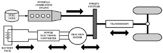
Figure 1.
Parallel hybrid electric vehicle mechanism [10].
The basic principle is that the different motors work better at different speeds; the electric motor is more efficient at producing torque, or turning power, and the combustion engine is better for maintaining a high speed (better than a typical electric motor) [11]. Changing power sources with appropriate timing and in the right circumstances facilitates energy efficacy and fuel efficiency. Abundant hybrid models (i.e., the Boeing Fuel Cell Demonstrator Airplane, Hybrid FanWings) have been presented in order to take advantage of each and handle uncertainties [11]. This hybrid methodology is proposed, taking benefits of both the conventional power source (i.e., a turbine engine’s consistent output) and an electricity power system (i.e., fastest response for utility) [12] so as to enhance safety if engine failure happens.
3. Conceptual Framework and Design for Experiment
This drone application proposal [4] is shown as Figure 2.
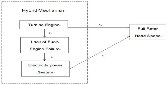
Figure 2.
Proposed theoretical foundation of the hybrid mechanism.
Figure 2 explains the sequence for the operation procedure of the proposed hybrid mechanism. Generally speaking, (1) A turbine engine offers the power for rotor head speed; (2) if the turbine engine suffers from lack of fuel/engine failure, (3) the electricity power system offers auxiliary dominance so as to (4) keep the full rotor head speed for a helicopter.
Moreover, this experiment contains the following sections:
- 3.1. MD-8 remote control helicopter: We decided to choose the MD-8 as the model for our test because this helicopter has great reputation in the R/C industry due to its agility, rigidity, and simplicity for maintenance. The dimensions for this remote control helicopter are 230 (L) × 30 (W) × 55 cm (H). Further, we also needed to design and build a conversion kit which contained new reinforced helicopter body frames so as to accommodate both a complete turbine engine device and an electricity power system. This conversion kit was made by composite materials of carbon-fiberglass and aluminum-alloy poles with the dimensions of 50 (L) × 15 (W) × 30 cm (H). The turbine engine was installed in this kit via a set of custom-made engine mount and gear box mount.
- 3.2. Kingtech K-45 turbo-prop airplane turbine engine: This merchandise is a miniature version of real aircraft turbine engines with the dimensions of 33.5 (L) × 15 (W) × 8 cm (H). Not only the theory, but the operations are the same as those of authentic aircraft turbine engines. This engine weighs 1.8 kg, offers the output of 5.2 kW (6.97 hp), and consumes 5%-lubricant jet A1 fuel at 180 g/min with engine’s rpm 170,000 (maximum output shaft, 9000 rpm). Most importantly, Kingtech is a world-famous but domestic company in Taiwan. We are proud to add to the impression of products made in Taiwan.
- 3.3. An electricity power system: This category includes an electric motor (with dimensions of 5.77 (L) × 2.8 cm (R)) which weighs 526 g (with the maximum rated output of 4.4Kw/6.03hp at the maximum rated current of 100 Amps); an electricity amperage supplier—160 Amps, (i.e., also known as motor speed controller); and 44.4 V (3250 mAh) batteries.
- 3.4. Electronic control devices: This group has servos, gyro, transmitter, receiver, and 7.4 V batteries.
- 3.5. Supplementary parts: 3 × 810 mm main and 3 × 120 mm tail blades, and ground support accessories. Most important is the next point.
- 3.6. The hybrid mechanism. Since we have to operate both Kingtech K-45 turbo-prop airplane turbine engine and the electronic motor consecutively, we had to design and make a brand new, innovative hybrid mechanism for testing our concept. This hybrid mechanism had to meet the following requirements. First of all, based on the conventional design, the electronic motor’s driver shaft needed to vertically attach to the main driving gear. There is no other space for the turbine engine to engage onto the main driving gear. Therefore, we had to add a 2nd set of driving gears for the turbine engine. Moreover, due to a helicopter’s restricted accommodation for keeping vertical as well as horizontal balance, we decided to create a set of bevel gears so as to cope with the turbine engine’s output and rpm. Most important, both sets of driving gears have an individual one-way bearing module so as to independently transmit either the turbine engine’s performance or the electronic motor’s output onto the extended main shaft for spinning the rotor head system. The proposed hybrid mechanism is shown as Figure 3.
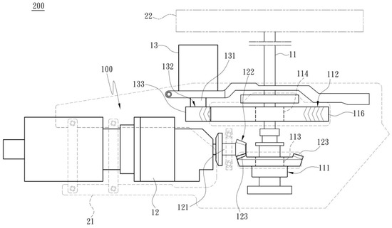 Figure 3. The hybrid mechanism proposal.
In more specific terms, number in Figure 3 denote the following:
- 100—hybrid mechanism;
- 11—driver shaft for propellers;
- 111—first transmission gear;
- 112—second transmission gear;
- 113,114—one-way bearing module;
- 116—first v-shaped teeth gear;
- 12—turbine engine;
- 121—first output shaft;
- 122—first bevel driving gear;
- 123—first bevel gear;
- 13—electronic motor;
- 131—second output shaft;
- 132—second driving shaft;
- 133—second v-shaped teeth gear;
- 200—drone application/remote control helicopter;
- 21—carbon-fiberglass frame of conversion kit;
- 22—propellers.
Operationally, once we start the turbine engine (12), this engine rotates the first output shaft (121) and the first bevel driving gear (122) so as to drive first bevel gear (123). Consequently, through the first transmission gear (111), the one-way bearing module (113) is driven to turn the driver shaft for the propellers (11). Finally, the propellers (22) revolve at a specified speed so as to provide sufficient thrust for lifting the remote control helicopter. In more specific terms, we set the turbine engine’s (12) output shaft rpm to 9000; the gear ratio between the first bevel driving gear (122) and the first bevel gear (123) was 1:4. Accordingly, the rpm of driver shaft for propellers (11) was 2250. However, the realistic rpm reaches only 70–80% (1575–1800) of the calculated result due to aerodynamic drag [13,14].
On the other hand, if accidentally, the turbine engine suffers from lack of fuel/engine failure, the electronic motor (13) works right away to drive second output shaft (131), second driving shaft (132), and second v-shaped teeth gear (133) so as to rotate first v-shaped teeth gear (116). Consequently, the second transmission gear (112) and one-way bearing module (114) are driven to turn driver shaft for the propellers (11). Finally, propellers (22) revolve at specified speed so as to provide sufficient thrust for lifting the remote control helicopter. In more specific terms, the electronic motor’s (13) maximum rated output shaft rpm/v is 520 KV. The gear ratio between the second v-shaped teeth gear (133) and the first v-shaped teeth gear (116) is 1:11. Accordingly, the rpm of driver shaft for propellers (11) is 520 KV × 44.4 V/11 = 2099. However, the realistic rpm reaches only 70–80% (1469–1679) of the calculated result due to aerodynamic drag [13,14].
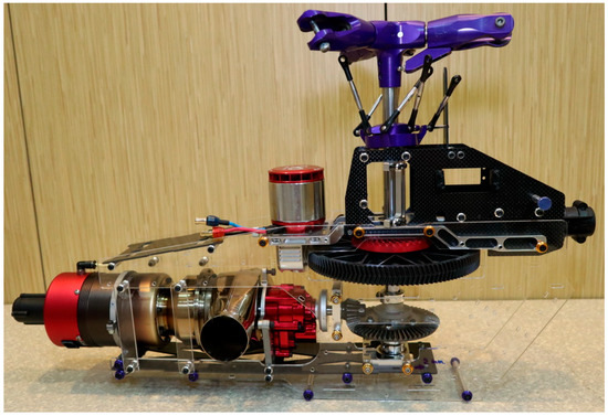
Figure 4.
Transparent model.
Figure 5 represents the complete hybrid mechanism proposal in the conversion kit.
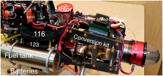
Figure 5.
Complete hybrid mechanism. (116- first v-shaped teeth gear, 123- first bevel gear).
4. Discussion
We successfully test ran and flew this newly designed R/C helicopter, as shown in Figure 6.
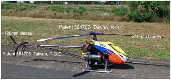
Figure 6.
The new design of an R/C helicopter.
Operationally, we used a radio control transmitter to maintain the main blades’ rpm at 1500 for both turbine engine and electronic motor power sources, respectively. Generally speaking, the maximum speed for the tip of the helicopter’s blades is approximately 180–220 m/s. In other words, the speed is around 0.55–0.66 Mach at standard atmospheric pressure (i.e., the environmental temperature might have moderate influence on the speed) [15]. So as such, 1500 rpm × 0.9 m × 2 × 3.14 = 141.3 m/s which is roughly 70% of the maximum speed mentioned above for producing much less vicious variations in altitude or velocity of the helicopter [16]. The pitch administered to the main blades was between –5 and 10 degrees. This new design R/C helicopter started to lift at the pitch of 2° and hovered at that of 4.5°. The propellers are of the controllable-pitch type so that they could have a low pitch when taking off and a higher pitch for high speed, horizontal flight [16].
Empirically validated, within 1 second, the electricity power system offers supplementary motive force as soon as the turbine engine shuts down (and/or has a flameout). Furthermore, the electricity power system offers sufficient dynamism for the above helicopter (9.5 kg) not only hover at a specific altitude but also ascend to the sky. The capacity of those batteries is adequate for this model helicopter to fly for 5 minutes. In other words, the 5-minute airtime is a very safe and satisfactory period of time for a harmless landing. Through this hybrid mechanism, two individual power sources are interconnected to make either turbine engine or electronic motor flight possible [16].
This paper contains both theoretical and experimental pioneering research, presenting a model for the solution to an engineering problem: the fastest way to solve the crisis of unavoidable/unpredicted engine failure for helicopters. In the near future, we hope to apply this practical evidence in the helicopter industry for decreasing human injuries and/or fatalities. The ultimate purpose of this manuscript is to save people’s lives.
For any specific helicopter, the hybrid mechanism needs to be redesigned for adaptation. The impending electricity power system (i.e., kW output of an electric motor, capacity of an electricity amperage supplier, and measurements of batteries) needs to be redefined. In other words, the overall weight-to-power ratio must be re-calculated.
The findings of this study solve only the lack of fuel/engine failure jeopardy. We might need to conduct some other experiments for straightening out personnel mistakes and/or mechanical failures.
5. Patents and Recognitions
In Figure 5, the complete hybrid mechanism is in the process of patent application on the date of submission for publication. The conversion kit which contains new, reinforced helicopter body frames (Patent pending) won a Gold Medal in the 2016 Kaoshiung International Invention and Design Expo. In Figure 6, both Triple Blades’ Flybarless Main Rotor Head Complete System (Patent M584707, Taiwan, R.O.C.) and Triple Blades’ Tail Rotor Assembly (Patent M584706, Taiwan, R.O.C.) won Gold Medals in the 2016 Kaoshiung International Invention and Design Expo. Additionally, the latter innovation obtained The Award of the President of the Jury in the same exhibition [17].
Author Contributions
Conceptualization, methodology, and experimental project administration (construction of this experimental R/C helicopter, and test flight), K.K.-S.C.; writing—original draft preparation, K.K.-S.C.; writing—review and editing, M.-L.T. and Y.-J.C.; confirmation of the rigidity of the materials in the construction of this experimental R/C helicopter, J.-L.L. and R.H.-L.H. All the authors have read and approved the final version for submission. All authors have read and agreed to the published version of the manuscript.
Funding
This research received no external funding.
Acknowledgments
This work has been supported by the KingTech Turbines and MingDa Technology Corp.
Conflicts of Interest
The authors declare no conflict of interest.
References
- Crouse Law Offices. What Causes Helicopter Accidents? Available online: http://www.helicopterlawyers.com/causes_helicopter_accidents.html (accessed on 18 August 2018).
- IHST-CIS. Helicopter accidents: Statistics, trends and causes; IHST Regional Partners Panel: Louisville, KY, USA, 2 March 2016; Available online: http://www.ihst.org/portals/54/symposium/2016/Presentation%20IHST-CIS_2016.pdf (accessed on 18 August 2018).
- Byrne, G. Why helicopters crash: Fuel, pilot error and mechanical failure. The Irish Times. 15 March 2017. Available online: https://www.irishtimes.com/news/ireland/irish-news/why-helicopters-crash-fuel-pilot-error-and-mechanical-failure-1.3010682 (accessed on 18 August 2018).
- Lynskey, J.; Thar, K.; Thant, Z.O.; Choong, S.H. Facility location problem approach for distributed drones. Symmetry 2019, 11, 118–129. [Google Scholar] [CrossRef]
- Robb, G.C. Helicopter crashes 101, 2014. Robb & Robb Web site. Available online: https://www.robbrobb.com/helicopter-crashes-101 (accessed on 18 August 2018).
- Pilot tells police what caused New York City helicopter crash that killed 5. CBS News. 13 March 2018. Available online: https://www.cbsnews.com/news/pilot-tells-police-what-caused-new-york-city-helicopter-crash-that-killed-5/ (accessed on 18 August 2018).
- Barnard, M. Why are Teslas quicker than gas cars? CleanTechnica. 19 December 2015. Available online: https://cleantechnica.com/2015/12/19/teslas-quicker-gas-cars/ (accessed on 18 August 2018).
- Dhiman, H.S.; Deb, D.; Muresan, V.; Unguresan, M.-L. Multi-criteria decision making approach, for hybrid operation of wind farms. Symmetry 2019, 11, 675–692. [Google Scholar] [CrossRef]
- Wikipedia. Hybrid Vehicle. Available online: https://en.wikipedia.org/wiki/Hybrid_vehicle (accessed on 9 November 2019).
- Hussein, M.M. An Argument for the Adoption of Hybrid Electric Vehicles. December 2014. Available online: https://www.researchgate.net/publication/274371964_An_Argument_for_the_Adoption_of_Hybrid_Electric_Vehicles (accessed on 14 December 2019).
- Liu, Y.; Martinez, L.; Qin, K. A comparative study of some soft rough sets. Symmetry 2017, 9, 252–272. [Google Scholar] [CrossRef]
- Pawar, P.; Nielsen, R.; Prasad, N.; Ohmori, S.; Prasad, R. Hybrid mechanisms: Towards an efficient wireless sensor network medium access control. In Proceedings of the 2011 14th International Symposium on Wireless Personal Multimedia Communications (WPMC), Brest, France, 3–7 October 2011. [Google Scholar]
- Hoerner, S.F. Fluid-Dynamic Drag: Theoretical, Experimental and Statistical Information; Hoerner Fluid Dynamics: Vancouver, BC, Canada, 1965. [Google Scholar]
- Hoerner, S.F. Fluid Dynamic Drag: Practical Information on Aerodynamic Drag and Hydrodynamic Resistance; Hoerner Fluid Dynamics: Vancouver, BC, Canada, 1965. [Google Scholar]
- Hoerner, S.F. Fluid-Dynamic Lift: Practical Information on Aerodynamic and Hydrodynamic Lift; Hoerner Fluid Dynamics: Vancouver, BC, Canada, 1992. [Google Scholar]
- Piancastelli, L.; Gatti, A.; Frizziero, L.; Ragazzi, L.; Cremonini, M. CFD analysis of the Zimmerman’s V173 stol aircraft. J. Eng. Appl. Sci. 2015, 10, 8063–8070. [Google Scholar]
- Kaohsiung KIDE international invention and design exhibition remote control jet helicopter shines. RC Tech Magazine. 13 December 2016. Available online: http://www.rctech.com.tw/2016/12/kide.html (accessed on 30 October 2018).
© 2019 by the authors. Licensee MDPI, Basel, Switzerland. This article is an open access article distributed under the terms and conditions of the Creative Commons Attribution (CC BY) license (http://creativecommons.org/licenses/by/4.0/).