


Development of a High-Rotational Submersible Pump for Water Supply


Abstract
:1. Introduction
- (1)
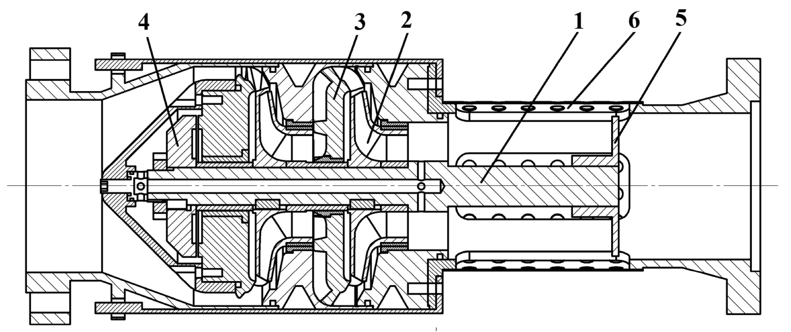
- Development of the structural scheme of the pump and design of the elements of its flowing part with reduced weight and dimensions;
- (2)
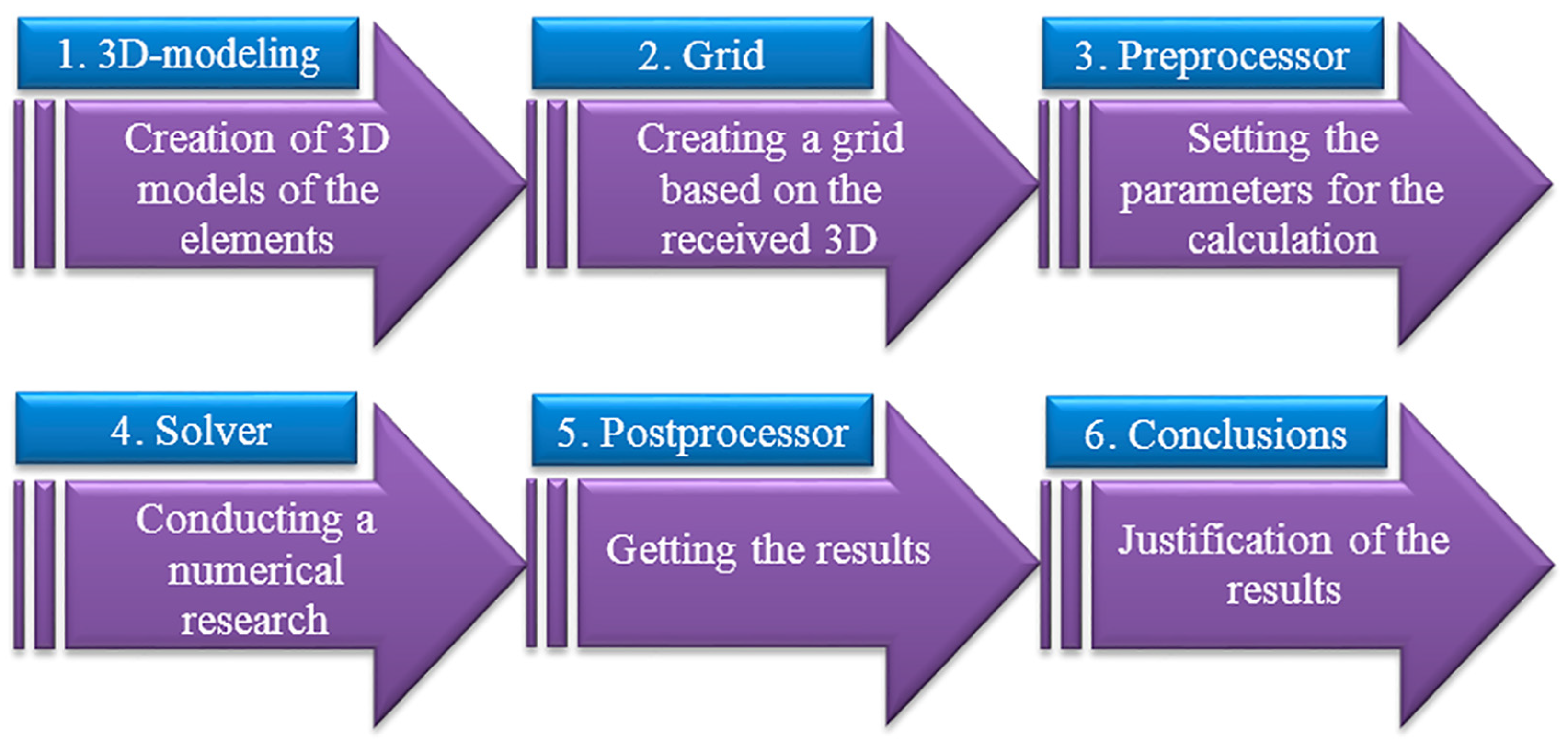
- Selection of the numerical research method, initial conditions, and turbulence model;
- (3)
- Performing a numerical study of hydrodynamic processes in the elements of the flowing part of the developed pump in order to ensure a high level of energy efficiency and obtain the resulting energy characteristics of the pump;
- (4)
- Analysis of research results.
2. Materials and Methods
3. Results
4. Discussion
5. Conclusions
Author Contributions
Funding
Data Availability Statement
Acknowledgments
Conflicts of Interest
References
- Kumar, J.; Gopi, S.; Amirthagadeswaran, K. Redesigning and numerical simulation of gating system to reduce cold shut defect in submersible pump part castings. Proc. Inst. Mech. Eng. Part E J. Process Mech. Eng. 2023, 237, 971–981. [Google Scholar] [CrossRef]
- Ramez, A.; Al-Hakimi, W.; Perozo, N.; Jaeger, P. Real-time liquid rate and water cut prediction from the electrical submersible pump sensors data using machine-learning algorithms. ACS Omega 2023, 8, 12671–12692. [Google Scholar] [CrossRef]
- Aydin, H.; Merey, S. Design of Electrical Submersible Pump system in geothermal wells: A case study from West Anatolia, Turkey. Energy 2021, 230, 120891. [Google Scholar] [CrossRef]
- Tong, S.; Zhao, H.; Liu, H.; Yu, Y.; Li, J.; Cong, F. Multi-objective optimization of multistage centrifugal pump based on surrogate model. J. Fluids Eng. 2020, 142, 011101. [Google Scholar] [CrossRef]
- Al-Mudhafar, W.J.; Wood, D.A.; Al-Obaidi, D.A.; Wojtanowicz, A.K. Well placement optimization through the triple-completion gas and downhole water sink-assisted gravity drainage (TC-GDWS-AGD) EOR process. Energies 2023, 16, 1790. [Google Scholar] [CrossRef]
- Kondus, V.; Gusak, O.; Yevtushenko, J. Investigation of the operating process of a high-pressure centrifugal pump with taking into account of improvement the process of fluid flowing in its flowing part. J. Phys. Conf. Ser. 2021, 1741, 012012. [Google Scholar] [CrossRef]
- Firatoglu, Z.A.; Alihanoglu, M.N. Investigation of the effect of the stages number, the impeller outlet width, and the impeller outlet angle on the performance of an industrial electric submersible pump. J. Fluids Eng. 2022, 144, 081203. [Google Scholar] [CrossRef]
- Lingom, P.M.; Song-Manguelle, J.; Betoka-Onyama, S.P.; Nyobe-Yome, J.M.; Doumbia, M.L. A Power Quality Assessment of Electric Submersible Pumps Fed by Variable Frequency Drives under Normal and Failure Modes. Energies 2023, 16, 5121. [Google Scholar] [CrossRef]
- Liu, Z.; Jiang, B.; Zuo, J.; Pan, Y. Influence of clocking position between impeller and guide vane on the performance of well submersible pump. J. Liaoning Tech. Univ. 2023, 42, 198–206. [Google Scholar]
- Arocena, V.M.; Abuan, B.E.; Reyes, J.G.T.; Rodgers, P.L.; Danao, L.A.M. LAM Numerical investigation of the performance of a submersible pump: Prediction of recirculation, vortex formation, and swirl resulting from off-design operating conditions. Energies 2021, 14, 5082. [Google Scholar] [CrossRef]
- Bhattacharjee, P.; Hussain, S.A.I.; Dey, V. Failure mode and effects analysis for submersible pump component using proportionate risk assessment model: A case study in the power plant of Agartala. Int. J. Syst. Assur. Eng. Manag. 2023, 14, 1778–1798. [Google Scholar] [CrossRef]
- Malonda, P.; Ngoma, G. Numerical Investigation of a High-Capacity Vertical Submersible Two-Stage Pump and Realization of an Experimental Test Bench for Determining the Strains and the Stresses on a Pump Shaft. In Proceedings of the 13th International Conference on Simulation and Modeling Methodologies, Technologies and Applications SIMULTECH, Lisbon, Portugal, 12–14 July 2023; pp. 393–400. [Google Scholar] [CrossRef]
- ECW-10. Submersible Pumps. Available online: https://www.ECW-ukraine.com.ua/ectv-10-serii (accessed on 1 October 2023).
- Kondus, V.; Sotnyk, M.; Sokhan, A.; Antonenko, S.; Rybalchenko, V. Assessment of the Life Cycle Cost and Improvement of the Parametric Series of Torque-Flow Pumps. In Advanced Manufacturing Processes V; Tonkonogyi, V., Ivanov, V., Trojanowska, J., Oborskyi, G., Pavlenko, I., Eds.; Springer: New York, NY, USA, 2023. [Google Scholar]
- Monte Verde, W.; Kindermann, E.; Biazussi, J.L.; Estevam, V.; Foresti, B.P.; Bannwart, A.C. Experimental investigation of the effects of fluid viscosity on electrical submersible pumps performance. SPE Prod. Oper. 2023, 38, 1–19. [Google Scholar] [CrossRef]
- Glovatskii, O.; Ergashev, R.; Nasirova, N.; Rashidov, J.; Kholbutaev, B. Experimental tests of submersible vane pumps. E3S Web of Conf. 2023, 401, 05065. [Google Scholar] [CrossRef]
- Plotkin, J.; Levchenko, N.; Shyshkanova, G.; Levchenko, S. Development of energy enterprises in the context of green transformation. Int. J. Eng. Sci. (Ukraine) 2023, 10, G22–G33. [Google Scholar] [CrossRef]
- Antonenko, S.; Sapozhnikov, S.; Kondus, V.; Chernobrova, A.; Mandryka, A. Creation a universal technique of predicting performance curves for small-sized centrifugal stages of well oil pump units. J. Phys. Conf. Ser. 2021, 1741, 012011. [Google Scholar] [CrossRef]
- Bulgarelli, N.; Biazussi, J.; Verde, W.; Perles, C.; Castro, M.; Bannwart, A. Experimental investigation on the performance of Electrical Submersible Pump (ESP) operating with unstable water/oil emulsions. J. Petrol. Sci. Eng. 2021, 197, 107900. [Google Scholar] [CrossRef]
- Pavlenko, I.; Trojanowska, J.; Gusak, O.; Ivanov, V.; Pitel, J.; Pavlenko, V. Estimation of the reliability of automatic axial-balancing devices for multistage centrifugal pumps. Period. Polytech. Mech. Eng. 2019, 63, 52–56. [Google Scholar] [CrossRef]
- Han, Y.; Bai, L.; Du, D.; Shi, W.; Zhou, L. Effects of tip clearance on energy performance of three-stage electrical submersible pump. Geoenergy Sci. Eng. 2023, 226, 211696. [Google Scholar] [CrossRef]
- Arocena, V.M.; Abuan, B.E.; Reyes, J.G.T.; Rodgers, P.L.; Danao, L.A.M. Reduction of Entrained Vortices in Submersible Pump Suction Lines Using Numerical Simulations. Energies 2020, 13, 6136. [Google Scholar] [CrossRef]
- Pavlenko, I.; Ciszak, O.; Kondus, V.; Ratushnyi, O.; Ivchenko, O.; Kolisnichenko, E.; Kulikov, O.; Ivanov, V. An Increase in the Energy Efficiency of a New Design of Pumps for Nuclear Power Plants. Energies 2023, 16, 2929. [Google Scholar] [CrossRef]
- Yang, Y.; Wu, S.; Wang, C.; Jiao, W.; Ji, L.; An, C.; Ge, J. Effect of effuser throat diameter on the internal flow structure and energy characteristics of the jet pump. Energy Rep. 2023, 9, 2075–2086. [Google Scholar] [CrossRef]
- Dykas, S.; Wilk, A. Determination of the flow characteristic of a high-rotational centrifugal pump by means of CFD methods. Task Q. 2008, 12, 245–253. [Google Scholar]
- Zhang, Y.; Han, J.; Huang, B.; Zhang, D.; Wu, D. Excitation force on a pump-jet propeller: The effect of the blade number. Ocean Eng. 2023, 2811, 114727. [Google Scholar] [CrossRef]
- Andrusiak, V.O.; Lugova, S.O.; Medvid, S.A.; Tkach, P.Y.; Rudenko, A.A. Effect of front impeller seal leakages on centrifugal stage characteristics. J. Phys. Conf. Ser. 2021, 1741, 012036. [Google Scholar] [CrossRef]
- Zhou, W.; Yu, D.; Wang, Y.; Shi, J.; Gan, B. Research on the fluid-induced excitation characteristics of the centrifugal pump considering the compound whirl effect. FU Mech. Eng. 2023, 21, 223–238. [Google Scholar] [CrossRef]
- Pavlenko, I.; Kulikov, O.; Ratushnkyi, O.; Ivanov, V.; Pitel’, J.; Kondus, V. Effect of impeller trimming on the energy efficiency of the counter-rotating pumping stage. Appl. Sci. 2023, 13, 761. [Google Scholar] [CrossRef]
- Rogovyi, A.; Korohodsky, V.; Medviedev, Y. Influence of Bingham fluid viscosity on energy performances of a vortex chamber pump. Energy 2021, 218, 119432. [Google Scholar] [CrossRef]
- Sun, Z.; Wang, L.; Ge, H.; Yuan, H.; Tang, F. Experiment on pressure pulsation in impeller of large submersible tubular pump. Trans. of the Chin. Soc. Agric. Mach. 2023, 54, 155–160. [Google Scholar] [CrossRef]
- Rzhebaeva, N.K.; Rzhebaev, E.E. Calculation and Designing of Centrifugal Pumps; Sumy State University: Sumy, Ukraine, 2016; p. 205. Available online: https://essuir.sumdu.edu.ua/handle/123456789/44432 (accessed on 18 September 2023).
- Patil, A.; Morrison, G. Affinity Law Modified to Predict the Pump Head Performance for Different Viscosities Using the Morrison Number. ASME J. Fluids Eng. 2018, 141, 021203. [Google Scholar] [CrossRef]
- Liu, Y.; Xie, Z.; Zhou, Y.; Peng, Z.; Liu, Z. CFD simulation and optimization of electric submersible pump considering the effect of heavy oil viscosity. Pet Sci. 2023, 45, 170–177. [Google Scholar] [CrossRef]
- Fleder, A.; Böhle, M. A systematical study of the influence of blade length, blade width, and side channel height on the performance of a side channel pump. ASME J. Fluids Eng. 2015, 137, 121102. [Google Scholar] [CrossRef]
- Zhou, W.; Wang, Y.; Li, C.; Zhang, W.; Wu, G. Analysis of fluid-induced force of centrifugal pump impeller with compound whirl. Alex. Eng. J. 2020, 59, 4247–4255. [Google Scholar] [CrossRef]
- ISO 13709:2009; Centrifugal Pumps for Petroleum, Petrochemical and Natural Gas Industries. International Organization for Standardization: Geneva, Switzerland, 2009. Available online: https://www.iso.org/standard/41612.html (accessed on 18 September 2023).
- Han, C.; Liu, J.; Yang, Y.; Chen, X. Influence of blade exit angle on the performance and internal flow pattern of a high-speed electric submersible pump. Water 2023, 15, 2774. [Google Scholar] [CrossRef]


| Parameters of ECW Pump | ECW-10-65-150 (⌀260 mm) | ECW 10-63-150 (⌀260 mm) | ECW 8-63-110 (⌀205 mm) | ECW 8-65-160 (⌀205 mm) | |||
|---|---|---|---|---|---|---|---|
| Berdiansk | RPE Kharkiv Electro-Mechanical Plant | Livny City | Azov-Energomash | Berdiansk City | Livny City | Livny City | |
| Casing pipe diameter | 260 mm | 205 mm | |||||
| Flow rate, m3/h | 65 | 63 | 63 | 63 | 65 | 65 | 65 |
| Head, m | 22.5 | 150 | 150 | 150 | 110 | 110 | 160 |
| Electric motor, kW | 27 | 45 | 35 | 37 | 45 | 32 | 33 |
| Supply voltage, V | 31.5 | 380 | 380 | 380 | 380 | 380 | 380 |
| Length, mm | 2000 | 2040 | 1520 | 2040 | 3100 | 1930 | 2580 |
| Mass, kg | 200 | 294 | 198 | 294 | 147 | 173 | 235 |
| Min well flow rate, m³/h | 130 | 130 | 126 | 130 | 126 | 130 | 130 |
| Nominal current, A | 93.0 | 92.5 | 77.0 | 92.5 | 66.0 | 70.0 | 104 |
| Number of stages, pcs | 8 | 7 | 7 | 8 | 13 | 13 | 13 |
| Duty Point | Flow Rate Q, m3/h | Head, m | Efficiency, % |
|---|---|---|---|
| 0.05 | 3.25 | 18.97 | 10.55 |
| 0.10 | 6.50 | 19.28 | 19.85 |
| 0.20 | 13.0 | 19.28 | 33.98 |
| 0.40 | 26.0 | 19.14 | 51.88 |
| 0.60 | 39.0 | 18.26 | 64.41 |
| 0.80 | 52.0 | 16.40 | 72.33 |
| 1.00 | 65.0 | 14.75 | 74.55 |
| 1.20 | 78.0 | 11.97 | 70.17 |
| 1.40 | 91.0 | 8.440 | 58.53 |
| 1.60 | 104 | 4.300 | 35.65 |
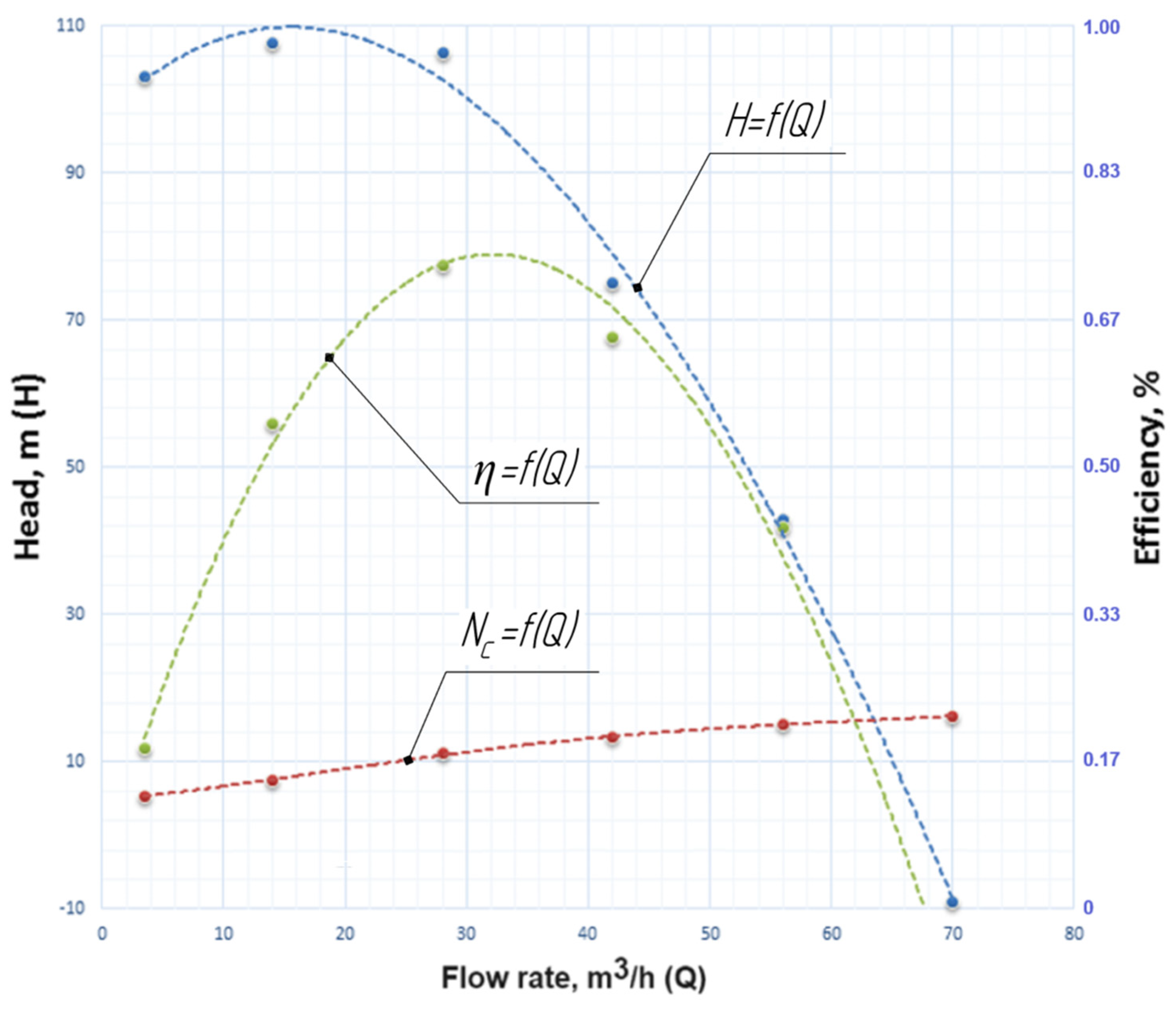
| Duty Point | Flow Rate Q, m3/h | Head, m | Efficiency, % |
|---|---|---|---|
| 0.05 | 3.5 | 103.2 | 18.26 |
| 0.20 | 14 | 107.7 | 54.87 |
| 0.40 | 28 | 106.3 | 72.82 |
| 0.60 | 42 | 75.13 | 64.79 |
| 0.80 | 56 | 42.96 | 43.14 |
| 1.00 | 70 | 9.040 | 10.60 |
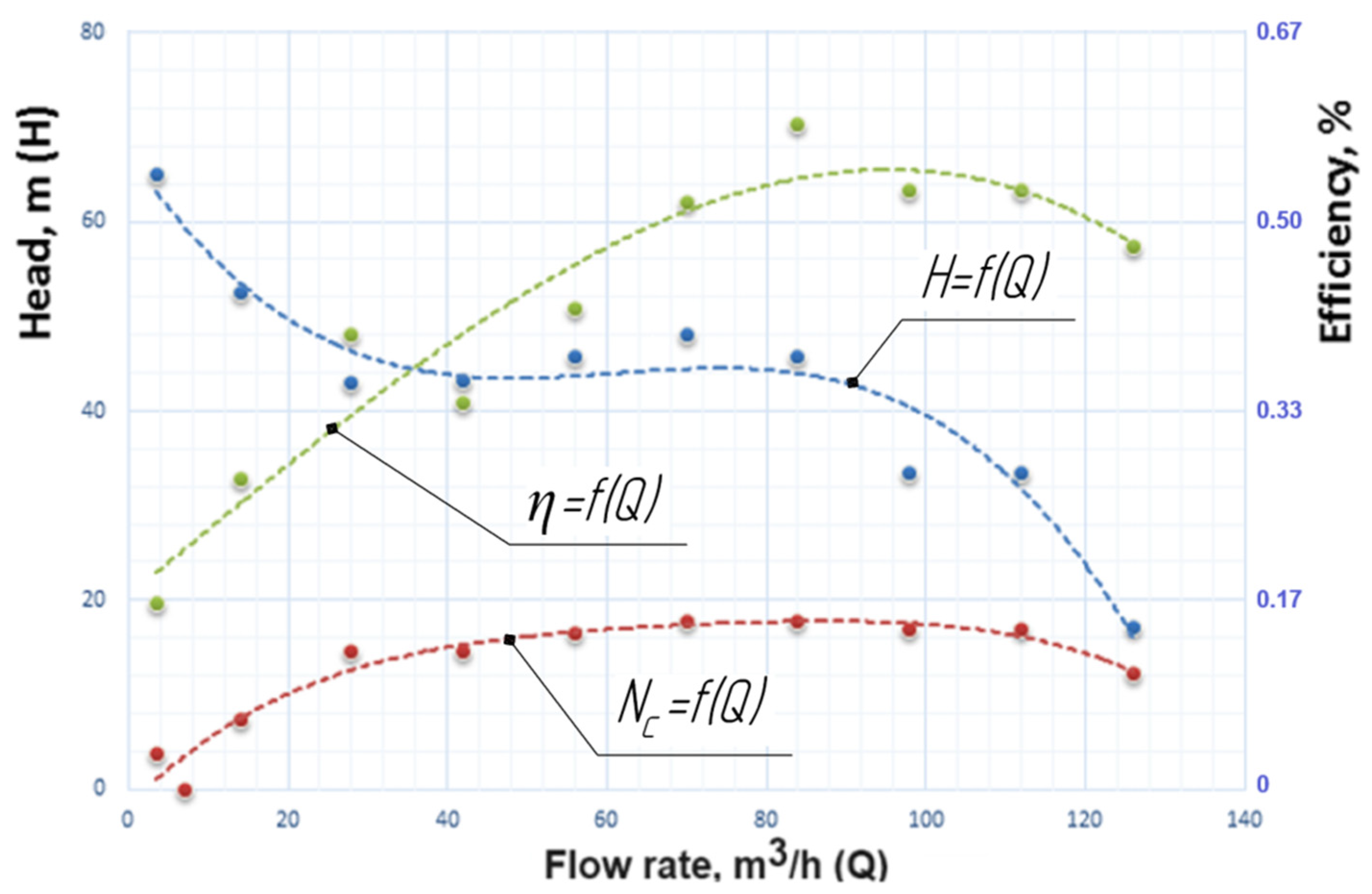
| Duty Point | Flow Rate Q, m3/h | Head, m | Efficiency, % |
|---|---|---|---|
| 0.05 | 3.5 | 65.0 | 16.36 |
| 0.20 | 14 | 52.5 | 27.30 |
| 0.40 | 28 | 43.1 | 40.00 |
| 0.60 | 42 | 43.2 | 34.07 |
| 0.80 | 56 | 45.8 | 42.38 |
| 1.00 | 70 | 48.0 | 51.77 |
| 1.20 | 84 | 45.7 | 58.65 |
| 1.40 | 98 | 33.4 | 52.69 |
| 1.60 | 112 | 33.5 | 52.75 |
| 1.80 | 126 | 17.0 | 47.81 |
| Duty Point | Flow Rate Q, m3/h | Head, m | Efficiency, % |
|---|---|---|---|
| 0.05 | 3.5 | 74.57 | 14.14 |
| 0.10 | 7.0 | 78.30 | 23.84 |
| 0.20 | 14 | 80.21 | 40.80 |
| 0.40 | 28 | 80.08 | 58.05 |
| 0.60 | 42 | 78.78 | 68.51 |
| 0.80 | 56 | 72.61 | 73.72 |
| 1.00 | 70 | 61.54 | 75.74 |
| 1.20 | 84 | 48.87 | 74.46 |
| 1.40 | 98 | 34.47 | 68.10 |
| 1.60 | 112 | 19.35 | 54.16 |
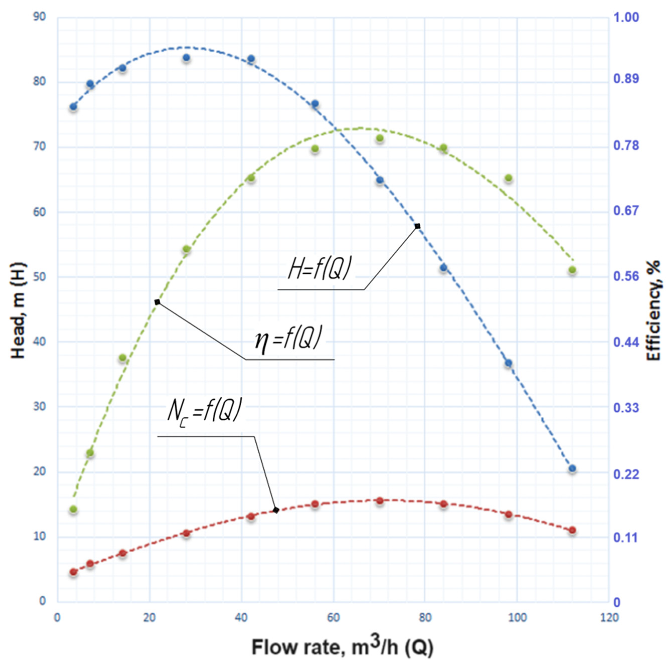
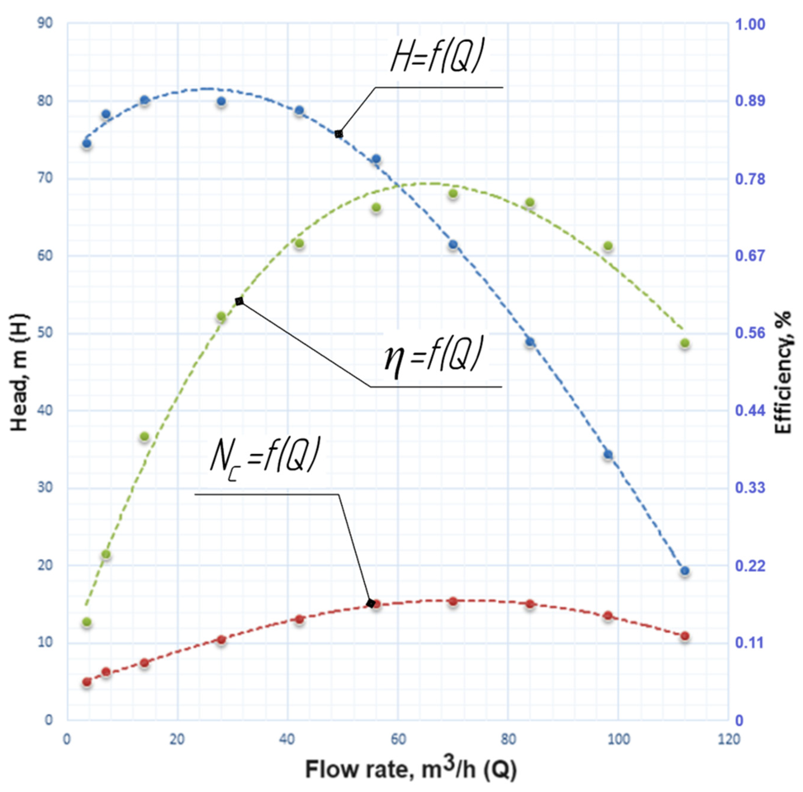
| Duty Point | Flow Rate Q, m3/h | Head, m | Efficiency, % |
|---|---|---|---|
| 0.05 | 3.5 | 76.22 | 15.88 |
| 0.10 | 7.0 | 79.75 | 25.61 |
| 0.20 | 14 | 82.30 | 41.85 |
| 0.40 | 28 | 83.88 | 60.46 |
| 0.60 | 42 | 83.73 | 72.52 |
| 0.80 | 56 | 76.79 | 77.62 |
| 1.00 | 70 | 65.04 | 79.42 |
| 1.20 | 84 | 51.52 | 77.85 |
| 1.40 | 98 | 36.83 | 72.51 |
| 1.60 | 112 | 20.49 | 56.81 |
| Parameter | Basic Stage Model | Developed Stage Models | |||
|---|---|---|---|---|---|
| 01 | 02 | 03 | 04 | ||
| Flow rate, m3/h (max efficiency mode) | 65 | 28 | 84 | 70 | 70 |
| Head, m (max efficiency mode) | 14.75 | 106.31 | 47.96 | 61.54 | 65.04 |
| Head, m (nominal mode) | 14.75 | 9.04 | 45.67 | 61.54 | 65.04 |
| Efficiency, % (max mode) | 74.55 | 72.82 | 58.65 | 75.44 | 79.42 |
| Efficiency, % (nominal mode) | 74.55 | 10.60 | 51.77 | 75.44 | 79.42 |
| Power consumption, W (max efficiency mode) | 3504 | 11,139 | 18,718 | 15,560 | 15,621 |
| Power consumption, W (nominal mode) | 3504 | – | 17,824 | 15,560 | 15,621 |
Disclaimer/Publisher’s Note: The statements, opinions and data contained in all publications are solely those of the individual author(s) and contributor(s) and not of MDPI and/or the editor(s). MDPI and/or the editor(s) disclaim responsibility for any injury to people or property resulting from any ideas, methods, instructions or products referred to in the content. |
© 2023 by the authors. Licensee MDPI, Basel, Switzerland. This article is an open access article distributed under the terms and conditions of the Creative Commons Attribution (CC BY) license (https://creativecommons.org/licenses/by/4.0/).
Share and Cite
Kondus, V.; Pavlenko, I.; Kulikov, O.; Liaposhchenko, O. Development of a High-Rotational Submersible Pump for Water Supply. Water 2023, 15, 3609. https://doi.org/10.3390/w15203609
Kondus V, Pavlenko I, Kulikov O, Liaposhchenko O. Development of a High-Rotational Submersible Pump for Water Supply. Water. 2023; 15(20):3609. https://doi.org/10.3390/w15203609
Chicago/Turabian StyleKondus, Vladyslav, Ivan Pavlenko, Oleksandr Kulikov, and Oleksandr Liaposhchenko. 2023. "Development of a High-Rotational Submersible Pump for Water Supply" Water 15, no. 20: 3609. https://doi.org/10.3390/w15203609
APA StyleKondus, V., Pavlenko, I., Kulikov, O., & Liaposhchenko, O. (2023). Development of a High-Rotational Submersible Pump for Water Supply. Water, 15(20), 3609. https://doi.org/10.3390/w15203609