Article

Permeability Tests and Numerical Simulation of Argillaceous Dolomite in the Jurong Pumped-Storage Power Station, China

School of Earth Science and Engineering, Hohai University, Nanjing 211100, China
*
Author to whom correspondence should be addressed.
Water 2023, 15(18), 3320; https://doi.org/10.3390/w15183320
Submission received: 10 August 2023 / Revised: 12 September 2023 / Accepted: 19 September 2023 / Published: 21 September 2023

Abstract

:
Due to its poor hydro-physical properties and other characteristics, argillaceous dolomite is susceptible to seepage failure under high water pressure, affecting the seepage stability of a rock mass. To ensure the safety of the project, when the argillaceous dolomite is present, it is necessary to study the conditions pertaining to its seepage failure. Taking the argillaceous dolomite of Jurong Pumped Storage Power Station as the research object, the spatial distribution, occurrence, scale, degree of weathering, and mechanical and hydrogeological characteristics of the argillaceous dolomite were studied. Through on-site water pressure tests and laboratory variable head tests, the permeability characteristics of argillaceous dolomite were analyzed, and the hydraulic conductivity of the argillaceous dolomite in the upper reservoir and underground powerhouse areas was quantified. The argillaceous dolomite specimens were collected, and seepage failure tests were conducted to determine the critical water pressure for its seepage failure. Based on the results of the laboratory tests, a numerical model of groundwater flow was established. By changing the water level of the upper reservoir and the measures of the anti-seepage and drainage, the seepage stability of the argillaceous dolomite was discussed. The actual water pressure of argillaceous dolomite in the underground powerhouse area was identified during the operation of the Jurong pumped-storage power station. The calculations show that when fully enclosed anti-seepage and drainage measures are taken for the underground powerhouse, the maximum head of water is 98 m, which is lower than the critical water pressure of seepage failure for the argillaceous dolomite. Therefore, no seepage failure will occur. The results provide a scientific basis for the anti-seepage and drainage design of the underground powerhouse area.

1. Introduction

Argillaceous dolomite is considered a weak inter-layer, which is a special type of engineering geological body with poor hydro-physical properties. It exerts a significant influence on the seepage stability of rock mass, and it is prone to seepage failure under high water pressure. Ning and Tang believed that weak interlayer is the root-cause of many geological disasters, causing serious economic losses both at home and abroad [1]. Yu et al. [2] found that the microstructure of the weak inter-layer (e.g., micro-fracture and pore space) was changed by the variations in external loads and its permeability property was changed by the establishment of the discrete element method (DEM) model, which affected its seepage stability.
In the research on the seepage failure of weak interlayers, some scholars have achieved certain results from theoretical analysis, physical model tests, and numerical simulation. Zhang proposed a shear damage model to describe the shear mechanical behavior of argillaceous dolomite based on the shear deformation-damage characteristics of the weak inter-layer [3]. Many scholars have established intrinsic creep models of argillaceous dolomite from the theory through the existing models to represent the deformation process of weak interlayers and analyze the deformation damage mechanism [4,5,6,7]. Among them, Chen theoretically constructed an intrinsic creep model considering the weakening coefficient and damage of the enclosing rock containing soft and weak interlayers and verified its feasibility through numerical simulation and on-site testing [7].
Laboratory tests, such as mechanical and physical model tests, are commonly used to study the failure characteristics of argillaceous dolomite. Laboratory mechanical tests include uniaxial compression tests, biaxial compression tests, triaxial compression tests, shear tests, etc. Some scholars investigated the strain-behavior and deformation damage mode of soft and weak rock formations through laboratory tests [8,9,10,11,12]. The laboratory tests can be combined with numerical simulation. Luo et al. [13] conducted a uniaxial compression test on the rock body containing weak inter-layer and used DEM-FEM coupled numerical simulation method to reveal the evolution of the internal stresses and the changes in the stress distribution in the specimen. The damage mechanism, seepage characteristics, and deformation properties of weak interlayers under different working conditions were investigated through physical modeling tests, and the unevenness of plastic deformation and stress distribution was considered to be the main factors influencing the stability of weak interlayers [14,15,16,17,18].
Liu et al. [19,20] established numerical models and imported them into FLAC3D for calculation to explore the deformation and seepage failure mechanism of soft and weak interlayers on slopes and the sensitivity of each parameter of the soft rock. Lin et al. [21] investigated the deformation and damage characteristics of slopes containing muddy, soft, and weak interlayers using the DEM, which shows signs of creep. The finite element method was also used to study the rotational-translation damage mechanism of slopes containing soft and weak interlayers, and its reliability was verified [21,22,23,24].
Several argillaceous dolomites are found in the upper reservoir and underground powerhouse of the Jurong Pumped Storage Power Station (JPSPS) with different degrees of weathering, which make it easy to induce seepage failure when encountering high water pressure. After the normal operation of the reservoir, argillaceous dolomite may undergo seepage failure under high water pressure. The objective of this study is to conduct experimental seepage failure (hydraulic fracturing) tests and determine the critical water pressure at which argillaceous dolomite undergoes seepage failure. At the same time, using a 3D groundwater flow numerical model and considering the fully enclosed anti-seepage curtain and drainage conditions of the underground powerhouse, the actual water pressure of argillaceous dolomite can be calculated. Compared to the critical water pressure obtained from experiments with the calculated water pressure, whether the argillaceous dolomite has undergone seepage failure can be determined. The research results can provide a scientific basis for optimizing the anti-seepage and drainage measures of the underground powerhouse.

2. Case Study

2.1. Project Overview

Taking argillaceous dolomite in the JPSPS as the research object, the power station is located in Jurong City, Jiangsu Province, about 26 km from Jurong city, and 65 km from Nanjing City, China [25]. The total installed capacity is 1350 MW. The normal storage level of the upper reservoir is 267 m with a total storage capacity of 17.44 million m3. The normal storage level of the lower reservoir is 81 m with a total storage capacity of 20.35 million m3. The power station consists of the upper and lower reservoirs, dams, water conveyance systems, underground powerhouses, and permanent flood discharge structures (Figure 1) [26]. The upper reservoir is located on the southwest side of the main peak of Lunshan Mountain and is formed by excavating and filling the valleys of the main peak of Lunshan Mountain. The lower reservoir is formed by damming at the Zimei Bridge, which is mainly located at the tail of Lunshan Reservoir. It is equipped with drainage holes and a spillway. Within the main peak of Lunshan Mountain, the water conveyance system and underground powerhouses are placed with a total length of approximately 1400 m. The underground powerhouse area is mainly located at elevations of 30 m to 40 m.

2.2. Stratal and Distribution Characteristics of Argillaceous Dolomite

The strata in the power station area belong to the Ningzhen Formation, the Lower Yangtze Formation, and the Yangtze Formation Region. The lithology is mainly Sinian, Cambrian, and Permian strata (Figure 2) [26]. Sinian Dengying Group (Z2dn) mainly consists of fine crystal dolomite and internal clastic dolomite with a thickness of 150–227 m. The Cambrian Guanyintai Group (∈2–3gn) is mainly composed of chert-bearing nodules or chert-banded dolomite mixed with argillaceous and calcareous dolomite with a thickness of 150–210 m. Baotaishan Group (∈1p) mainly consists of a thin (less than 10 cm) to medium (10–50 cm) layer of argillaceous dolomite, siliceous dolomite, and cataclastic dolomite with an exposed thickness of 39–78 m. The argillaceous dolomite is thin, and the surface is strongly weathered. The upper section of the Mufushan Group (∈1m2) is mainly composed of phosphorous siliceous rock, phosphorous limestone dolomite, phosphorite, thick-bedded. Permian Longtan Group (P2l) comprises carbonaceous mudstone and argillaceous siltstone, which is distributed around the water inlet or outlet of the lower reservoir with a thickness of about 100 m.
The Quaternary Upper Pleistocene and Holocene strata cover a large area above the old strata, while the other strata are exposed to the surface on a small scale. The lithology of the upper reservoir and underground powerhouse is mainly composed of dolomite. The upper reservoir is located on the southwest side of the main peak of Lunshan Mountain, and the exposed argillaceous dolomite is strongly weathered with a thickness of 200–400 mm. The layer is mostly mixed with mud, and the thickness of mud is about 20–30 mm. There is a small amount of leakage at the contact surface with siliceous dolomite, and dissolved pores are developed, with pore sizes ranging between 20 mm to 50 mm (Figure 3a).
There are multiple weak interlayers in the water conveyance system and underground powerhouse, most of which are weakly to slightly weathered. The covering layer is mainly distributed at the foot of the mountain with a thickness of 2–8 m, and the underlying rocks are slightly weathered. The longitudinal wave velocity of rock mass measured by seismic waves is about 4400–5900 m/s. The lithology is mainly argillaceous dolomite in the lower part of the Cambrian Guanyintai Group and argillaceous dolomite in the Fortress Hill Formation. There are many diorite porphyrite veins intruded in the later stage, which also ranged from weakly to slightly weathered. The contact zone with surrounding rock is often corroded, where coarse crystal calcite veins are developed. Three argillaceous dolomites of Fortress Hill Formation are distributed at 0 + 135 m on the right of the stake mark in the underground powerhouse. The strike of argillaceous dolomite is N75° E, which is weakly weathered, and the thickness of them varies from 150 mm to 200 mm (Figure 3b). The strip of argillaceous dolomite has a relatively soft texture and a significant decrease in seepage stability when encountering high water pressure. It mainly develops along a layer with a dip angle of about 40°, and it is numbered UP1, UP2, and UP3 (left to right). The characteristics of argillaceous dolomite are summarized in Table 1.
It can be seen from Table 1 that the argillaceous dolomite is mainly thinly layered. The exposed rock masses in the upper reservoir are mostly weakly weathered with well-developed structural planes and distorted argillaceous dolomite. The main occurrence is N75° W/SW∠45°. The rock mass is weakly weathered with layers ranging in thickness from 150 mm to 400 mm. The surface is mostly mixed with mud with a thickness of 20–30 mm. There is some leakage at the contact surface with siliceous dolomite. The argillaceous dolomite in the underground powerhouse is weakly to slightly weathered. It exhibits complete to strong weathering after exposure to the air. Its thickness ranges from 150 mm to 200 mm. The research object herein is argillaceous dolomite, and the focus is not on its strength, but rather its response to water pressure.

3. Methods

3.1. Water Pressure Test

A water pressure test can determine the permeability parameters of rock mass based on the relationship between water pressure and flow rate. The water pressure test in the borehole was to divide the borehole into several test sections according to a specified length of 5 m and use different pressures to inject water into the test sections and measure its corresponding flow rate. Therefore, the permeable rate of the rock mass could be obtained. The hydraulic conductivity of the rock mass could be calculated based on the relationship between the permeable rate and hydraulic conductivity as given by [27].
q = Q L P
where q is the permeability rate of the test section (Lu), Q denotes the water flow rate under the maximum water pressure (L/min), L represents the length of the test section (m), and P is the maximum test pressure (MPa). The permeability (q) obtained from the water pressure test can be converted into the corresponding hydraulic conductivity of the rock mass in the water pressure section, namely [27],
K = 0.00258 q l g 1.32 L r
where K is the hydraulic conductivity of the rock mass (m/d), and r stands for the radius of the borehole (m).

3.2. Seepage Failure Test

The normal storage level of the upper reservoir in the JPSPS is 267 m, and the bottom elevation of the underground powerhouse is about 5 m. After impoundment, the water pressure of the underground powerhouse will increase significantly, and the argillaceous dolomite may undergo seepage failure, with associated adverse effects on the seepage stability of a rock mass. Therefore, the seepage failure test mainly focuses on the argillaceous dolomite on the right side of the underground powerhouse due to the relatively small influence of the upper reservoir. The test equipment includes a high pressure water pump, water pressure gauge, specimen holding device, etc. (Figure 4).
The test specimens were taken from the weak interlayers of argillaceous dolomite in the underground powerhouse (Table 1). These specimens were processed into specimens measuring 150 mm × 150 mm × 1500 mm. The middle location of the specimen was drilled (hole-diameter of 20 mm and a depth of 100 mm), and the small hole was connected to a high pressure water pump. The pressures measuring hole and water outlet hole were set on the side, and the diameter is 6 mm. The water outlet hole was not connected to the test hole, while the pressure measuring hole was connected to the test hole. Also, the hole was connected to a water pressure gauge with a measurement range of 0–8 MPa by a hose with a wall thickness of 100 mm. The accuracy of the water pressure gauge is 0.1 MPa. The experimental model device measured 350 mm × 350 mm × 350 mm, which was composed of organic glass with a thickness of 50 mm. The specimen was placed in the middle of the device, at a certain distance from the side-wall of the specimen holding device. The purpose was to avoid the lateral pressure of the specimen in contact with the side wall of the device during the test, and the resulting water pressure measured in the test is small and tends to be safe. During the experiment, the water pressure gradually increased. Meanwhile, the water pressure and flow rate were recorded each time, and the seepage failure of the rock specimens was observed. Under the action of the high water head, due to the presence of small fractures in the rock samples, there was a phenomenon of stress concentration at the fracture tip, which caused the fractures to expand and induces seepage failure, also known as hydraulic fracturing.

3.3. Variable Head Permeability Test

The test specimens of argillaceous dolomite include UP1, UP2, and UP3 from the underground powerhouse and UR1 from the upper reservoir. The variable head test model consists of an upper cover, a base, a sleeve seat, a ring knife, a permeable stone, a screw, etc. The device was composed of an infiltration container, a variable head pipe, a water supply bottle, an inlet pipe, etc. The length of the variable head pipe was 2.0 m, and the minimum graduation was 1.0 mm. During the experiments, the corresponding water head values at different times were recorded simultaneously, and the hydraulic conductivity of the specimen can be calculated based on the following equation [28].
K = 2.3 a l A ( t 2 t 1 ) l g h 1 h 2
where a is the cross-sectional area of the inner diameter of the variable head pipe, A is the cross-sectional area of the discharge section, l denotes the length of the seepage path, and h1 and h2 represent the water head values in the variable head pipe at t1 and t2, respectively.

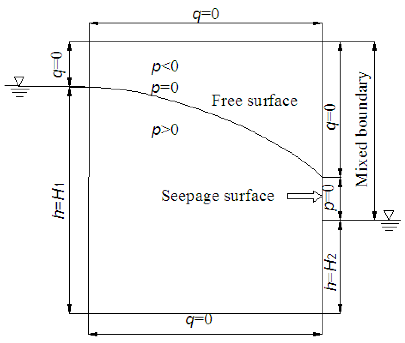
3.4. Numerical Simulation Method

The numerical simulation software COMSOL Multiphysics was used to simulate and calculate the water pressure of argillaceous dolomite. Assuming the study area is homogeneous and anisotropic, the mathematical model [29] for 3D groundwater movement is given by
ρ C m ρ g + S e S p t + ρ κ s η k r p + ρ g D = Q m
where Qm is the liquid source or sink term, D represents the position head, ρ is the fluid density, i.e., the density of water, g is gravitational acceleration, η is the fluid viscosity, Cm is the water capacity, Se denotes the saturation, S is the water storage coefficient, kr is the relative hydraulic conductivity, κs is the saturation hydraulic conductivity, and p refers to the pressure. The mixed boundary conditions in COMSOL can be expressed as
n · κ s η k r p + ρ g z = N 0 + R b ( H b H )
H b = z b + p b ρ g
H = z + p ρ g
where, Rb is the external conductivity, when Rb = 0, the mixed boundary is the second type of boundary condition, and when Rb approaches infinity, it is the first type of boundary condition, n is the direction of the normal outside the boundary plane, z is the axis coordinate, N0 is the inward flux, Hb represents the external total head, zb is the external elevation, pb is the external pressure, and H is the total hydraulic head.
The overflow boundary belongs to the third type of boundary condition, which combines the flow boundary and the head boundary Figure 5. In COMSOL, the meaning of the mixed boundary is to divide the boundary into two types of boundaries. The part above the free surface is the second type of boundary condition (zero-flow boundary), and there is no other pressure at the seepage surface except for the strong atmospheric pressure. Therefore, the location of the seepage surface is the first type of boundary condition, which only has a position head boundary (H = z). The calculation of mixed boundary-free surfaces is relatively complex, and currently it is mainly solved through continuous iterative approximation to obtain approximate solutions.

4. Analysis of Results and Discussion

4.1. Permeability Tests

A total of 1387 water pressure tests were conducted in 37 boreholes in the upper reservoir, and the permeability of different rock formations was statistically analyzed. The results show that the rock mass and argillaceous dolomite in the upper reservoir area have a low permeability. The karst development in the upper reservoir area is mainly characterized by dissolution fractures with a small amount of karst caves. The depth of development varies greatly, and karst caves are exposed at burial depths of 5.5 m, 10.2 m, 24.2 m, 26.8 m, 61.5 m, 48.16 m, 88.5 m, etc. The groundwater flow revealed by drilling is complex, and there are dissolution fractures that leak into the underground powerhouse. According to Equation (2), the hydraulic conductivity of rocks in the upper reservoir is calculated to be 1.0 × 10⁻⁶ to 1.0 × 10⁻⁴ cm/s, among which the hydraulic conductivity of argillaceous dolomite is 1.55 × 10⁻⁵ to 4.54 × 10⁻⁵ cm/s. Some 34 sections of water pressure tests were conducted on the underground powerhouse, and the results showed that the permeability of rock masses in different layers did not differ significantly, mainly in weakly permeable rock layers. The permeability of most test sections was 5–7 Lu; however, dissolution fractures were relatively well developed near the groundwater level, and the permeability of rock masses below the groundwater level was 4.44–6.3 Lu. The water pressure test did not reveal the existence of large karst leakage channels. According to Equation (2), the hydraulic conductivity of the rock strata in the underground powerhouse area is calculated to be between 1.0 × 10⁻⁶ to 1.0 × 10⁻⁴ cm/s.
Laboratory tests were conducted to determine the hydraulic conductivity of the argillaceous dolomite using the variable head test. To ensure the accuracy of the test results, five tests were conducted on UR1 specimens from the upper reservoir and UP1–UP3 specimens from the underground powerhouse (Table 2): the hydraulic conductivity of argillaceous dolomite in the upper reservoir is between 2.08 × 10⁻⁵ and 3.98 × 10⁻⁵ cm/s with an average value of 2.90 × 10⁻⁵ cm/s. The hydraulic conductivity of UP1 and UP2 in the underground powerhouse is not significantly different, while the hydraulic conductivity of UP3 is about three to four times that of UP1 and UP2. The hydraulic conductivity of the argillaceous dolomite in the underground powerhouse varies between 0.99 × 10⁻⁴ and 5.77 × 10⁻⁴ cm/s with an average value of 2.31 × 10⁻⁴ cm/s. Both are argillaceous dolomites, and the underground powerhouse area is about eight times larger than the upper reservoir area. Whether in the upper reservoir or underground powerhouse, the test results of hydraulic conductivity by the laboratory tests are consistent with the results of water pressure tests. These parameters are used as the initial values for the parameter inversion of the numerical model.

4.2. Seepage Failure Tests

Due to the distribution of argillaceous dolomite above the water level of the upper reservoir, the impact of reservoir water on the dolomite is not significant. Therefore, two tests were mainly conducted using the argillaceous dolomite specimens from the underground powerhouse for seepage failure tests. The test results show that the critical water pressure of the UP1 specimen at the beginning of seepage failure is 1.0 MPa, and that of the UP2 specimen is 1.1 MPa.
The P-Q and Q-t curves were drawn for two experiments based on the experimental results in Figure 4. The solid line in Figure 6a represents the pressure rise curve, while the dashed line represents the pressure drop curve. When the specimen undergoes seepage failure, the flow rate is found to increase, which indicates that under the action of test pressure, the microfractures present in the specimen have expanded or penetrated, and this seepage failure is irreversible. Figure 6b indicates that, before reaching the critical water pressure for specimen failure, the flow rate increases linearly with time. After exceeding the critical water pressure, due to rock failure, the slope increases, and the flow rate decreases with time.
With the increase in water pressure, there was no significant change in specimen UP1. When the water pressure increased to 1.0 MPa, cracks appeared in the sample, and the amount of water pressed into the specimen also increased, which indicates the specimen failure. Figure 7a shows the failure of the specimen when the water pressure stabilizes at 1 MPa. After 60 s, obvious cracks appeared in the sample, which gradually became larger. After 600 s, the crack size remained stable. Similar to UP1, when the water pressure increases to 1.1 MPa, the flow rate undergoes a significant change after 30 s for the specimen UP2, and visible cracks begin to appear at 60 s (Figure 7b). After 600 s, the number and size of cracks around the specimen increase significantly.
Some studies have shown that in the presence of lateral pressure, the critical water pressure of argillaceous dolomite will increase, the greater the lateral pressure, the greater the water pressure for the same seepage failure. According to the geological conditions of the underground powerhouse in JPSPS, the lateral pressure of UP1 and UP2 in the underground powerhouse is 0.5 MPa. Therefore, in combination with the results of the seepage failure test, the critical water pressure of argillaceous dolomite is 1.60 MPa and 1.50 MPa, respectively. Due to the storage water level of 267 m in the upper reservoir, the maximum static water pressure at the underground powerhouse is about 2.6 MPa, which is larger than the test value of argillaceous dolomite failure if the anti-seepage and drainage measures of the underground powerhouse are not considered.
Under the action of high water pressure, there will be a concentration area of local stress increase inside the argillaceous dolomite. At a point where the strength of the inner wall of the crack is weak, there may be a local high tensile stress zone, which causes local tensile stress to occur here, and causes the argillaceous dolomite to crack first here until it penetrates the sidewall. Therefore, it can be considered that the seepage failure of argillaceous dolomite is caused by the formation of small cracks in the internal pores, particles, particle boundaries, etc. of the rock mass under water pressure, which induces stress concentration and results in the continuous expansion and development of cracks under water pressure. At the same time, under high water pressure, the seepage stability of argillaceous dolomite also changes, mainly reflected in connection, lubrication, water wedge, and subsurface erosion/dissolution. Among them, the first three effects are generated by bound water, and the latter is generated by gravitational water. The high pressure water flow that seeps into the structural plane can have a mechanical erosion effect on the contacting muddy materials, which may lead to some small particles being carried away by the water flow, leading to the seepage failure of the muddy dolomite. The seepage failure test of this study showed that when the water pressure was less than 1.0 MPa, the test water pressures were 0.3 MPa, 0.6 MPa, and 1.0 MPa, respectively. When the water pressure is greater than 1.0 MPa, the increase in water pressure is 0.1 MPa, and the continuous stable time of water pressure in each stage is 1 min. The critical water pressure for the seepage failure of argillaceous dolomite is the water pressure at the time of the formation of small cracks. This water pressure does not take into account the increase in hydraulic conductivity caused by the increase in fracture width and the potential corrosion/dissolution effect. Therefore, the obtained critical water pressure may be relatively small by seepage failure tests, and future research hopes to address the critical water pressure under the subsurface erosion/dissolution.

4.3. Numerical Simulation

4.3.1. Model Area Discretization

The numerical simulation of groundwater flow in this project adopts polyhedral element discretization. For important areas, the mesh has been encrypted to meet the accuracy requirements of the model. The 3D model considers the upper reservoir, water conveyance system, underground powerhouse, lower reservoir, and other hydraulic structures of JPSPS, and finally generates 5,182,416 elements and 628,452 nodes (Figure 8).

4.3.2. Parameter Inversion Results

Due to the large range of parameter values used in numerical simulation, the parameter values obtained from experiments in a certain local area cannot reflect the parameter situation of the entire study area. Therefore, the hydraulic conductivities of fractured rocks and argillaceous dolomite obtained by the water pressure test and permeability coefficient test of the variable head, respectively, were used as the initial values for parameter inversion of the numerical model. By continuously adjusting these parameter values, the groundwater levels for different boreholes are listed in Table 3; the relative error between the measured and calculated water levels is less than 1%, indicating that the numerical model is reliable. The inversion values of the hydraulic conductivity, Kx, Ky, and Kz, for fractured rocks, are 0.26 m/d, 0.34 m/d, and 0.17 m/d, respectively.

4.3.3. Simulation and Prediction Results of Groundwater

There are two anti-seepage and drainage schemes for underground powerhouses in JPSPS (Figure 9). The red lines around the underground powerhouse in Figure 9 represent anti-seepage measures, while the blue lines denote drainage holes, which are connected through drainage galleries. Firstly, after a fully enclosed anti-seepage was designed around the perimeter of the underground powerhouse area, and four drainage galleries were arranged around the plant area, including the top layer, the upper layer, the middle layer, and the lower layer. There are drainage holes between adjacent drainage galleries. Secondly, the top of the underground powerhouse is not equipped with anti-seepage measures, only considering the curtain anti-seepage measures around the underground powerhouse. Also, four layers of drainage galleries are normal. Rainfall infiltration has become the main groundwater recharge source in the underground powerhouse. Considering extreme rainfall conditions, the rainfall is set to 20 cm/d. According to different reservoir water levels, anti-seepage schemes, and drainage systems, eight schemes are considered (Table 4).
Figure 10 shows the contour map of the groundwater level; groundwater flows from the upper and lower reservoirs to the underground powerhouse area, and the groundwater head in the powerhouse area has the lowest value. Due to the use of geomembranes and concrete panels for anti-seepage measures in the upper reservoir, the water head of the entire seepage field in the upper reservoir area is relatively high, showing that anti-seepage measures have played a good role in preventing leakage in the upper reservoir. The groundwater level in the lower reservoir is significantly lower than that in the upper reservoir.
It can be seen from Table 4 that, for Scheme 3, no anti-seepage measures are taken in the underground powerhouse area. At this time, the water head value around the powerhouse is significantly greater than the critical heads of seepage failure for the argillaceous dolomites UP1 and UP2 in the underground powerhouse, which implies seepage failure will occur. Compared with Schemes 3 and 4, when the anti-seepage measure is adopted, the head of water near the underground powerhouse will decrease significantly. At this time, the head of water near the underground powerhouse does not exceed the critical values for seepage failure of argillaceous dolomites UP1 and UP2, which indicates that under the condition of anti-seepage and drainage measures, the argillaceous dolomite in the underground powerhouse will not undergo seepage failure. When the water level of the upper reservoir is at the dead water level, the head of water on the underground powerhouse is significantly lower. The head of water on the underground powerhouse under Schemes 5–8 is lower than the critical water head associated with seepage failure. The above analysis indicates that, in the absence of anti-seepage measures, the argillaceous dolomites UP1 and UP2 may undergo seepage failure, adversely affecting the safety of the project. After adopting fully enclosed anti-seepage and drainage measures, the argillaceous dolomite did not reach the critical head required to induce seepage failure, which indicates the importance of anti-seepage and drainage systems in the underground powerhouse area.

5. Conclusions

The hydraulic conductivity of argillaceous dolomite in the power station area was determined through water pressure measurement and variable-head tests. The hydraulic conductivity of argillaceous dolomite in the upper reservoir is 2.08 × 10⁻⁵ to 3.98 × 10⁻⁵ cm/s with an average value of 2.90 × 10⁻⁵ cm/s. The hydraulic conductivity of argillaceous dolomite in the underground powerhouse in the underground powerhouse is 0.99 × 10⁻⁴ to 5.77 × 10⁻⁴ cm/s with an average value of 2.31 × 10⁻⁴ cm/s, which provides reliable permeability parameters for numerical modelling. The critical water pressure of argillaceous dolomite without lateral pressure was determined through seepage failure tests. The results showed that the critical water pressure values of UP1 and UP2 were 1.5 MPa and 1.6 MPa, respectively. Due to the normal storage water level of 267 m in the upper reservoir, the maximum static water pressure at the underground powerhouse is about 2.6 MPa, which is greater than the test value associated with argillaceous dolomite, giving rise to the possibility of seepage failure, but when anti-seepage and drainage measures were taken in the underground powerhouse, the maximum calculated water head was 98 m. The value did not reach the critical value of seepage failure for argillaceous dolomite, indicating the importance of anti-seepage and drainage systems in the underground powerhouse area.

Author Contributions

Conceptualization, X.Z.; methodology, X.Z. and W.Y.; validation, W.Y., J.Z., Y.H. and L.Z.; formal analysis, X.Z. and W.Y.; resources, X.Z.; data curation, W.Y., J.Z., Y.H. and L.Z.; writing—original draft preparation, X.Z.; writing—review and editing, W.Y., J.Z. and W.Y.; visualization, W.Y. and Y.H.; supervision, X.Z., Y.H. and L.Z.; project administration, X.Z. and L.Z.; funding acquisition, X.Z. and L.Z. All authors have read and agreed to the published version of the manuscript.

Funding

This research was funded by the National Natural Science Foundation of China Joint Fund Project, grant number U2240217.

Data Availability Statement

Not applicable.

Acknowledgments

The authors thank the School of Earth Sciences and Engineering at Hohai University for the partial support of the graduate students on this project.

Conflicts of Interest

The authors declare no conflict of interest.

References

  1. Ning, W.; Tang, H. Dynamic Response Law and Failure Mechanism of Slope with Weak Interlayer under Combined Action of Reservoir Water and Seismic Force. Water 2023, 15, 1956. [Google Scholar] [CrossRef]
  2. Yu, L.; Zheng, X.; Liu, Z.; Zhou, C.; Zhang, L. Multiscale Modelling of the Seepage-Induced Failure of a Soft Rock Slope. Acta Geotech. 2022, 17, 4717–4738. [Google Scholar] [CrossRef]
  3. Zhang, Z.; Wang, T. Failure Modes of Weak Interlayers with Different Dip Angles in Red Mudstone Strata, Northwest China. Bull. Eng. Geol. Environ. 2023, 82, 156. [Google Scholar] [CrossRef]
  4. Wei, E.; Hu, B.; Tian, K.; Cen, P.; Zhang, Z.; Wang, Z.; Chang, S. Study on the Nonlinear Damage Creep Model of the Weak Interlayer. Adv. Civ. Eng. 2022, 2022, 3566521. [Google Scholar] [CrossRef]
  5. Wang, Y.; Zhong, F.; Chu, H.; Wang, L. Study on Mechanism of Slope Instability with Weak Interlayer. Appl. Mech. Mater. 2011, 71–78, 3615–3618. [Google Scholar] [CrossRef]
  6. Cao, P.; Youdao, W.; Yixian, W.; Haiping, Y.; Bingxiang, Y. Study on Nonlinear Damage Creep Constitutive Model for High-Stress Soft Rock. Environ. Earth Sci. 2016, 75, 900. [Google Scholar] [CrossRef]
  7. Chen, F.; Su, R.; Yang, L.; Yang, X.; Jiao, H.; Zhu, C. Study on Surrounding Rock Deformation Laws of an Argillaceous Soft Rock Roadway Based on the Creep Damage Model. Front. Earth Sci. 2022, 10, 914170. [Google Scholar] [CrossRef]
  8. Luo, Z.; Zhang, Y.; Du, S.; Huang, M.; Lyu, Y. Experimental Study on Shear Performance of Saw-Tooth Rock Joint with Weak Interlayer under Different Moisture Contents and Filling Degrees. Front. Earth Sci. 2023, 10, 982937. [Google Scholar] [CrossRef]
  9. Zhao, N.; Zhang, Y.; Miao, H.; Meng, L. Study on the Creep and Fracture Evolution Mechanism of Rock Mass with Weak Interlayers. Adv. Mater. Sci. Eng. 2022, 2022, 5004306. [Google Scholar] [CrossRef]
  10. Hu, Q.; Cai, Q.; He, L.; Yang, X.; Ye, T.; Shi, R. Determination of the Peak and Residual Shear Strengths of the Sandwich Material in Slopes. Adv. Mater. Sci. Eng. 2017, 2017, 9641258. [Google Scholar] [CrossRef]
  11. Zhang, S.; Yun, X.; Song, Y.; Liu, W.; Yang, L. Fluid-Structure Coupling Creep Characteristics of Red-Bed Soft Rock in South China. Water 2022, 14, 4088. [Google Scholar] [CrossRef]
  12. Tomanovic, Z. Rheological Model of Soft Rock Creep Based on the Tests on Marl. Mech. Time Depend. Mater. 2006, 10, 135–154. [Google Scholar] [CrossRef]
  13. Luo, X.; Cao, P.; Liu, T.; Zhao, Q.; Meng, G.; Fan, Z.; Xie, W. Mechanical Behaviour of Anchored Rock Containing Weak Interlayer under Uniaxial Compression: Laboratory Test and Coupled DEM–FEM Simulation. Minerals 2022, 12, 492. [Google Scholar] [CrossRef]
  14. Li, L.-q.; Ju, N.-p. Effect of the Inclined Weak Interlayers on the Rainfall Response of a Bedded Rock Slope. J. Mt. Sci. 2016, 13, 1663–1674. [Google Scholar] [CrossRef]
  15. Huang, F.; Zhu, H.; Xu, Q.; Cai, Y.; Zhuang, X. The Effect of Weak Interlayer on the Failure Pattern of Rock Mass around Tunnel—Scaled Model Tests and Numerical Analysis. Tunn. Undergr. Space Technol. 2013, 35, 207–218. [Google Scholar] [CrossRef]
  16. He, Z.; Wang, B. Instability Process Model Test for Bedding Rock Slope with Weak Interlayer under Different Rainfall Conditions. Adv. Civ. Eng. 2018, 2018, 8201031. [Google Scholar] [CrossRef]
  17. Rong, P.; Zuo, Y.; Lin, J.; Chen, Q.; Zheng, L.; Jin, K. Study of Mechanical Properties and Failure Characteristics of Combined Rock Mass with Weak Interlayer. Geomech. Geophys. Geo-Energy Geo-Resour. 2022, 8, 89. [Google Scholar] [CrossRef]
  18. Jeon, S.; Kim, J.; Seo, Y.; Hong, C. Effect of a Fault and Weak Plane on the Stability of a Tunnel in Rock—A Scaled Model Test and Numerical Analysis. Int. J. Rock Mech. Min. Sci. 2004, 41, 658–663. [Google Scholar] [CrossRef]
  19. Liu, X.; Han, Y.; Li, D.; Tu, Y.; Deng, Z.; Yu, C.; Wu, X. Anti-Pull Mechanisms and Weak Interlayer Parameter Sensitivity Analysis of Tunnel-Type Anchorages in Soft Rock with Underlying Weak Interlayers. Eng. Geol. 2019, 253, 123–136. [Google Scholar] [CrossRef]
  20. Li, J.; Zhang, B.; Sui, B. Stability Analysis of Rock Slope with Multilayer Weak Interlayer. Adv. Civ. Eng. 2021, 2021, 1409240. [Google Scholar] [CrossRef]
  21. Lin, S.S.; Lo, C.M.; Lin, Y.C. Investigating the Deformation and Failure Characteristics of Argillite Consequent Slope Using Discrete Element Method and Burgers Model. Environ. Earth Sci. 2017, 76, 81. [Google Scholar] [CrossRef]
  22. Liu, X.; Du, X.; Zhou, J.; Sun, J. Finite Element Analysis of Deformation Characteristic for Weak Interlayer Foundation. Adv. Mater. Res. 2012, 594–597, 552–556. [Google Scholar] [CrossRef]
  23. Huang, M.; Wang, H.; Sheng, D.; Liu, Y. Rotational-Translational Mechanism for the Upper Bound Stability Analysis of Slopes with Weak Interlayer. Comput. Geotech. 2013, 53, 133–141. [Google Scholar] [CrossRef]
  24. Huang, M.; Fan, X.; Wang, H. Three-Dimensional Upper Bound Stability Analysis of Slopes with Weak Interlayer Based on Rotational-Translational Mechanisms. Eng. Geol. 2017, 223, 82–91. [Google Scholar] [CrossRef]
  25. Miao, K.; Bai, Z.; Huang, Y.; Huang, Y.; Su, Y. Research on Seepage Control of Jurong Pumped Storage Hydroelectric Power Station. Water 2022, 14, 141. [Google Scholar] [CrossRef]
  26. Chen, L.; Dong, X.; Miao, K.; Yang, W.; Huang, Y. Characteristics and Connectivity Analysis of Hidden Karst in Jurong Pumped Storage Power Station Area, China. Water 2023, 15, 2562. [Google Scholar] [CrossRef]
  27. SL 31-2003; Water Conservancy and Hydropower Engineering Borehole Pressure Test Specification. Ministry of Water Resources of the People’s Republic of China: Beijing, China, 2003.
  28. YS/T 5225-2016; Geotechnical Test Protocol. Ministry of Industry and Information Technology of the People’s Republic of China: Beijing, China, 2016.
  29. Phoon, K.-K.; Tan, T.S.; Chong, P.C. Numerical simulation of Richards equation in partially saturated porous media under relaxation and mass balance. Geotech. Geol. Eng. 2007, 25, 525–541. [Google Scholar] [CrossRef]
Figure 1. The location and layout of hydraulic structures for JPSPS.
Water 15 03320 g001
Figure 2. Typical geological profile of the study area.
Water 15 03320 g002
Figure 3. Photos of argillaceous dolomite in the study area (a) upper reservoir, and (b) underground powerhouse.
Water 15 03320 g003
Figure 4. The model device for seepage failure test (a) sketch map, and (b) experimental model device.
Water 15 03320 g004
Figure 5. Schematic representation of overflow boundary conditions.
Water 15 03320 g005
Figure 6. Curves of seepage failure tests for argillaceous dolomite (a) P-Q curve, and (b) Q-t curve.
Water 15 03320 g006
Figure 7. Seepage failure tests for argillaceous dolomite (a) specimen UP1, and (b) UP2.
Water 15 03320 g007
Figure 8. Finite element mesh.
Water 15 03320 g008
Figure 9. Design diagram for anti-seepage and drainage of underground powerhouse area.
Water 15 03320 g009
Figure 10. Contour map of groundwater levels at an elevation of 25 m (a) Scheme 1, (b) Scheme 3.
Water 15 03320 g010
Table 1. Characteristics of argillaceous dolomite in the study area.
NumberDistribution LocationOccurrenceWidth (mm)Geological DescriptionExposure Length (m)
UR1Northwest side of the upper reservoirN75° E
SW∠45°
15–40It is yellow-brown and contains mud and rock debris. It is weakly weathered with siliceous material. There is a small leakage at the contact surface of dolomite.
UP1Right side of underground powerhouseN75° W
SW∠45°
15–20It is grey-yellow, mixes with mud, and is weakly to slightly weathered during excavation. It exhibits complete to strong weathering after exposure to the air.
UP2N75° W
SW∠45°
15–20It is white and greyish-yellow and exhibits weak weathering.
UP3N75° E
SE∠60°
15–20It is grey-white and yellowish-brown, contains mud, and exhibits slight weathering.
Table 2. Test results of hydraulic conductivity for the argillaceous dolomite.
Number of TestsHydraulic Conductivity (cm/s)
UR1UP1UP2UP3
12.657 × 10−51.078 × 10−40.987 × 10−45.769 × 10−4
23.128 × 10−51.188 × 10−41.130 × 10−44.903 × 10−4
32.662 × 10−51.182 × 10−41.203 × 10−43.255 × 10−4
42.084 × 10−51.226 × 10−41.428 × 10−43.831 × 10−4
53.983 × 10−51.287 × 10−41.457 × 10−44.066 × 10−4
Table 3. Comparison between calculated and measured results.
Number of BoreholesMeasured
Groundwater Level
(m)
Calculated
Groundwater Level
(m)
Absolute Error
(m)
Relative Error
(%)
Z280.3079.60.700.19
Z4158.90159.650.750.47
Z5151.33151.160.170.11
Z9130.20130.280.080.06
Z10120.70121.530.830.53
Z13131.52131.80.280.21
Z15127.92128.740.820.64
Z16151.96150.471.490.98
Z17150.12149.130.990.66
Z21177.17177.580.410.23
Table 4. Design schemes of anti-seepage and drainage for underground powerhouse area and calculated water pressures.
Number
of Schemes
The Upper/Lower Reservoir Water Level (m)Anti-Seepage and Drainage MeasuresCalculated Hydraulic Head (m)Critical Head for Seepage Failure for UP1 (m)Critical Head for Seepage Failure for UP2 (m)Seepage Failure
1267/81Fully enclosed anti-seepage and drainage80160150No
2267/81Anti-seepage and drainage around the underground powerhouse82160150No
3267/81No anti-seepage measures160160150Yes
4267/81Anti-seepage and drainage around the underground powerhouse98160150No
5246/81Fully enclosed anti-seepage and drainage59160150No
6246/81Anti-seepage and drainage around the underground powerhouse61160150No
7246/81No anti-seepage measures140160150No
8246/81Anti-seepage and drainage around the underground powerhouse77160150No
Disclaimer/Publisher’s Note: The statements, opinions and data contained in all publications are solely those of the individual author(s) and contributor(s) and not of MDPI and/or the editor(s). MDPI and/or the editor(s) disclaim responsibility for any injury to people or property resulting from any ideas, methods, instructions or products referred to in the content.

