Article

Salt Removal by Chemically Modified Graphene in Capacitive Deionization (CDI)

1
Department of Water Resources and Environmental Engineering, Tamkang University, 151 Yingzhuan Road, Tamsui District, New Taipei City 25137, Taiwan
2
Water Treatment Science and Technology Research Center, Tamkang University, 151 Yingzhuan Road, Tamsui District, New Taipei City 25137, Taiwan
*
Author to whom correspondence should be addressed.
Water 2022, 14(9), 1379; https://doi.org/10.3390/w14091379
Submission received: 19 March 2022 / Revised: 9 April 2022 / Accepted: 20 April 2022 / Published: 24 April 2022

Abstract

:
Obtaining clean water from salt water by capacitive deionization (CDI) with chemically modified graphene (rGO) was explored in this study. Strong acid (HNO3:H2SO4 = 2:1) was employed to modify rGO to enhance its hydrophilicity and electrochemical properties. Characteristics of rGO with/without acid modification were analyzed by XRD, SEM, FTIR, contact angle, BET, and cyclic voltammetry (CV). Contributions of sulfonic acid groups, hydroxyl groups, and NO2 stretching after acid modification resulted in better wettability and higher specific capacitance of rGO. The contact angle for rGO dropped from 84.9° to 35.1° (am-rGO), indicating improved hydrophilicity of rGO with acid modification. The specific capacitance of am-rGO can reach 150.2 F/g at the scan rate of 1 mV/s. The average NaCl electrosorption capacity of the CDI process with am-rGO was 0.63 mg NaCl/g electrode (10.86 μmol NaCl/g electrode), which indicated rGO with acid modification can enhance the electrosorption capacity by 3.9 times. This study demonstrated that chemical modification can significantly improve the hydrophilicity, electrochemical properties, and electrosorption performance of rGO, which has potential for applications to other carbon-based materials for CDI systems to improve salt removal efficiency.

Graphical Abstract

1. Introduction

Clean water is essential for humans, and the accessibility of affordable clean water is a challenge for many countries due to growing population and extreme climate change. Novel water treatment technologies and nanomaterials have gained considerable attention, especially for removal of micropollutants [1], pesticides [2], heavy metals [3,4], antibiotics [5], and drugs [6]. Water treatment technologies for obtaining clean water from seawater and brackish water or reused water have been developed to solve the water shortage problems. Seawater is abundant water resource and brackish water is also a good water resource especially in the arid areas. Desalination technologies, such as multistage flash distillation (MSF), mechanical vapor compression (MVC), multi-effect distillation (MED), reverse osmosis (RO), and electrodialysis (ED), have been developed for decades. Although they are well-established technologies for desalination, these conventional desalination methods are high energy consumption processes and have secondary pollution issues [7,8]. Therefore, scientists have tried to develop a robust, energy efficient, cost effective, and environmentally benign process to obtain clean water.
Capacitive deionization (CDI) is an emerging technology for deionization from salt-containing water. CDI has many advantages, such as low energy demand, no secondary pollution, and easy operation and maintenance, and has been applied to desalination of brackish water [9,10], water softening [11], and wastewater treatment [12]. The principle of CDI is to apply an external electric field to the electrodes, and cations in the water are attracted by the negative electrode, while the anions are electrosorbed onto the opposite positive electrode. The core of the CDI system is the electrode material. Carbon-based materials, such as activated carbons [13,14], carbon aerogels [15], carbon nanotubes [16,17], and graphene [18], have been widely employed as electrode materials in CDI systems.
Graphene (rGO) has attracted much attention, due to its unique physical and chemical properties, since 2004 [7]. Graphene is a two-dimensional hexagonal lattice structure of a single layer of atomic thickness sp2-bonded carbon atoms, and has a unique mechanical structure and superior electronic properties, which has great potential for developing supercapacitors and electrode materials [19]. Graphene has a high theoretical specific surface area (2600 m2/g), excellent room temperature electrical conductivity (72 S/m), and good electrochemical stability, which makes it a good candidate as an electrode material [20].
Graphene was pioneered for CDI systems in 2009 [21]. Li et al. (2009) demonstrated the promising application of graphene as an electrode material for the electrosorption of sodium chloride. Even with a low specific surface area of graphene (14.2 m2/g), graphene still exhibited a high salt electrosorption capacity of 1.85 mg/g (31.6 μmol/g) [21]. More researches came after Li’s group with the modification of graphene to improve the performance of CDI. Among various modification methods, acid treatment has been demonstrated to be a simple method, by changing functional groups to enhance the specific surface area, pore volume, and wettability of graphene, which results in improving salt removal efficiency in CDI [18,20]. Li et al. (2010) showed that graphene modified with nitric acid and sulfuric acid (volume ratio = 1:1) had a larger specific area (222.01 m2/g) and pore volume (51.01 cm3/g). In comparison with the higher specific area of activated carbon (989.54 m2/g), the salt electrosorption capacity of acid-modified graphene was 1.36 mg/g (23.18 μmol/g), which is much higher than that of activated carbon (0.80 mg/g, 13.73 μmol/g) [18]. Jia and Zou (2012) improved the wettability of graphene via sulfonation, which attached an -SO3 functional group on graphene, resulting in not only an increased specific surface area by 55%, but also an enhancement of the electrosorption capacity to 109% [18].
In this study, we synthesized graphene by making porous graphene oxide (GO) via acid modification firstly, and then reduced porous GO to graphene (rGO) with hexamethylenetetramine (HMTA). The rGO with/without acid modification was used as the electrode material in the CDI process. The objective of this study was to investigate impacts of chemical modification on graphene properties and to determine CDI performance with chemically modified graphene.

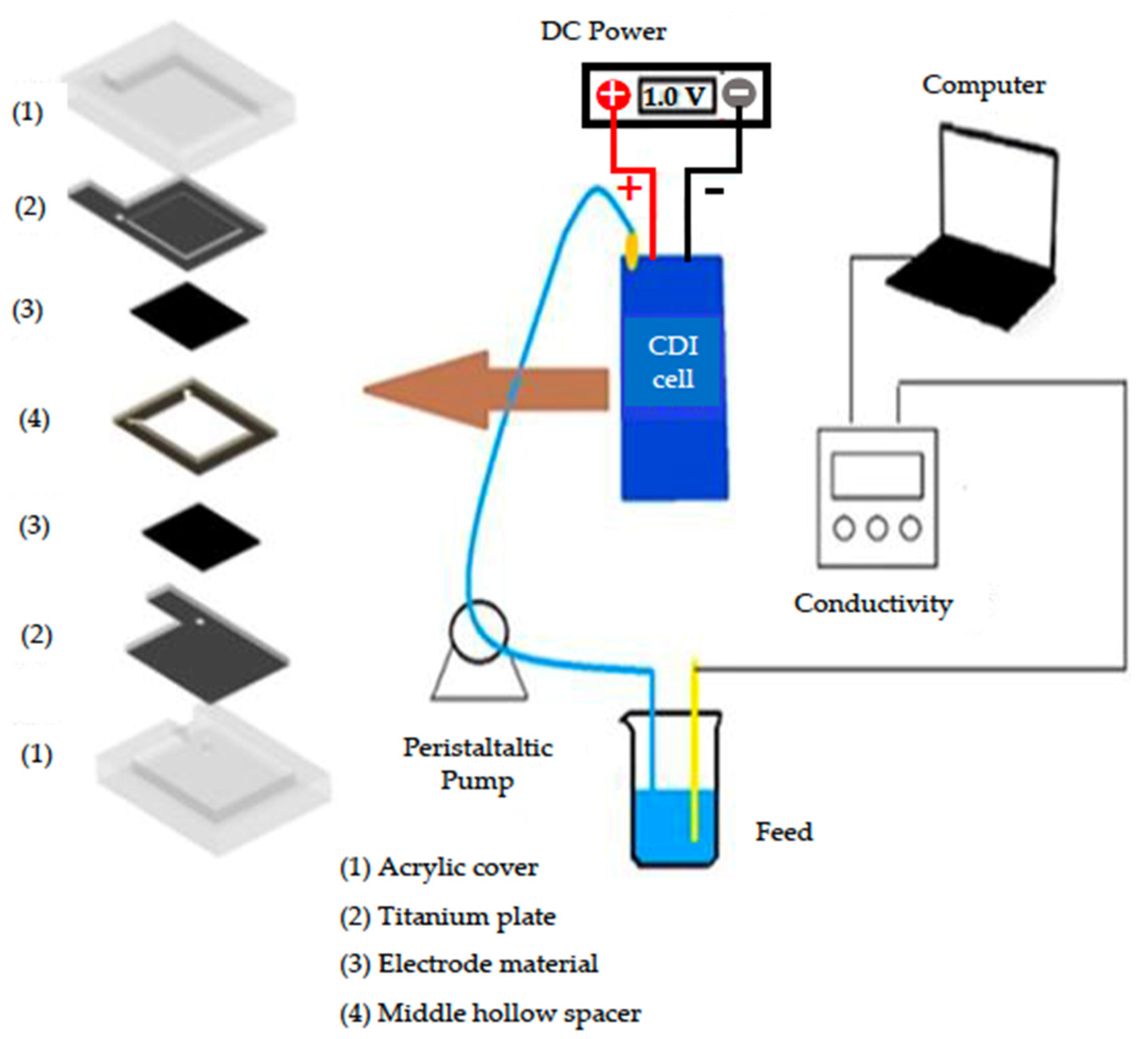
2. Materials and Methods

Chemicals used in this study were listed as follows: graphite powder (Aldrich, St. Louis, MI, USA), potassium permanganate (KMnO4, ≧99%, J.T. Baker, Phillipsburg, NJ, USA), sulfuric acid (H2SO4, 95–97%, Nihon Shiyaku Reagent, Osaka, Japan), hydrogen peroxide (H2O2, 35%, RDH, Charlotte, NC, USA), methyl alcohol (CH3OH, 100%, Macron, Radnor, PA, USA), hexamethylenetetramine (HMTA, C6H12N4, 99%, SIGMA, St. Louis, MO, USA), sodium hydroxide (NaOH, 96%, SHOWA, Minato-ku, Tokyo, Japan), nitric acid (HNO3, 69–71%, Nihon Shiyaku Reagent), hydrochloric acid (HCl, 35–37%, Nihon Shiyaku Reagent), polytetrafluoroethylene (PTFE, 95%, Alfa Aesar, Ward Hill, MA, USA), potassium bromide (KBr, 99%, Shimakyu’s Pure Chemicals, Osaka, Japan). Chemicals were used as received.
Graphene oxide (GO) was prepared from graphite powder based on modified Hummer’s method [22]. GO was further treated with a mixture of strong acids to form porous GO. Briefly, 0.15 g of GO mixed with 20 mL of nitric acid and 10 mL of sulfuric acid (HNO3:H2SO4 = 2:1) by ultrasonication and then heated to 90 °C and stirred for 4 h. After acid modification, the porous GO was filtered and washed with deionized water several times and then dried at 60 °C [23,24]. Porous GO was then reduced by green reductant, HMTA. An amount of 1 g of porous GO was added to 200 mL of deionized water. After ultrasonication for 10 min, the temperature of the mixture was raised to 60 °C and then 10 g of NaOH was added. The reduction reaction was carried out by adding 2.5 g of HMTA and mixing for 15 min with purging nitrogen to reduce the oxygen in the solution. The product was washed with DI water for several times and then filtered and dried at 60 °C [25]. The product generated from acid modification firstly and then reduction to rGO was denoted as am-rGO. Graphene without acid pretreatment was denoted as rGO.
The characteristics of the graphene with/without acid treatment were examined using XRD, SEM, FTIR, and BET analyses, contact angle measurement, and cyclic voltammetry (CV). X-ray diffraction (Bruker AXS-D8A) was conducted with a scan rate of 0.04°/s at 2θ = 5–80°. The corresponding crystalline information of XRD peaks was analyzed by DIFFRAC.EVA V3.0 software (Billerica, MA, USA). A scanning electron microscope (JEOL JSM-6500 F) analysis was carried out to determine the surface morphologies of rGO. The functional groups of the graphene were determined using Fourier transform infrared spectroscopy (Thermo, Nicolet iS5). The graphene was firstly dried and ground into powder, and then uniformly mixed with the dried potassium bromide (KBr) powder by a weight ratio of graphene: KBr = 1:100. The mixed powder was pressed into a light-permeable sample piece. The analysis software used in FTIR was OMNIC 8.2 (Waltham, MA, USA). The specific surface area and pore characteristics of the graphene were determined using a surface analyzer (ASAP 2020M) based on the N2 adsorption/desorption isotherm. The specific surface area was calculated using the Brunauer–Emmett–Teller (BET) method. The pore diameter was obtained using the BJH method [26]. The contact angle instrument was first ten angstroms (FTA 125). A 4 μL diameter water droplet was dropped on the surface of the graphene. The first moment of contact between the water droplet and the material was captured to record the contact angle.
The electrochemical properties of rGO were explored by cyclic voltammetry (CV) using an electrochemical analyzer (CHI 6273E) with a three-electrode system, in which platinum wire and Ag/AgCl were used as a counter and reference electrode, respectively. The CV was carried out in 1 M NaCl electrolytes between −0.4 to 0.8 V at various scan rates of 1, 5, 10, 50, 100 mV/s. The specific capacitance of rGO or am-rGO was calculated as follows [27]:
Specific   capacitance   ( F / g ) = V a V c I   d V 2 m v ( V c V a )
m: electrode weight (g), v: potential scanning speed (V/s), Vc: high potential (V), Va: low potential (V), I: current (A).
Salt removal experiments were conducted in a batch-mode CDI system, in which the NaCl solution was continuously circulated from a peristaltic pump into the CDI cell, and the effluent was returned into the solution, as depicted in Figure 1. The size of the graphene electrode was 40 × 40 mm. The spacer distance between two electrodes was 1 mm. An external voltage was applied at 1.0 V, controlled by a direct current power supply. The initial NaCl concentration was 50 mg/L and the total volume of NaCl solution was 50 mL with a flow rate of 13 mL/min. The electrosorption for both electrode materials was operated at 1.0 V, while for desorption (regeneration) processes, the reversed 1.0 V was applied. The electrosorption duration of rGO electrode material for each cycle was 3 min. The regeneration (desorption) time required for the rGO electrode material for three cycles was 4, 6, and 5 min. For am-rGO, the electrosorption time for three cycles was 2, 8, and 8 min. Desorption time for am-rGO for three cycles was 10, 21, and 21 min. The conductivity changes in the solution were continuously monitored to obtain the removal efficiency and electrosorption capacity of NaCl. The removal efficiency of NaCl based on conductivity measurements was calculated as follows [23]:
Removal   efficiency   ( % ) = ( C 0 C t ) C 0 × 100 %
Co: initial conductivity of NaCl solution for each electrosorption cycle (μS/cm), Ct: final conductivity of NaCl solution for each electrosorption cycle (μS/cm).
The electrosorption capacity is defined as the amount of NaCl (mg) electro-adsorbed based on the weight of electrode material (g), which was calculated as follows [28]:
Electrosorption   capacity   ( mg   NaCl / g   electrode ) = ( C o C t ) × V t M
Co: initial concentration (mg/L) of NaCl in the system, Ct: final concentration (mg/L) of NaCl at electrosorption equilibrium, Vt: volume of NaCl solution (L), M: electrode weight (g).

3. Results and Discussion

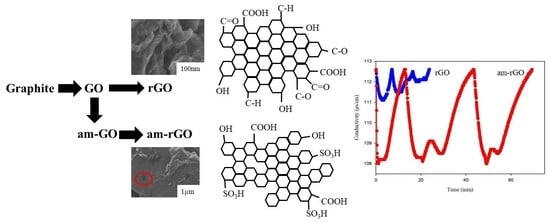
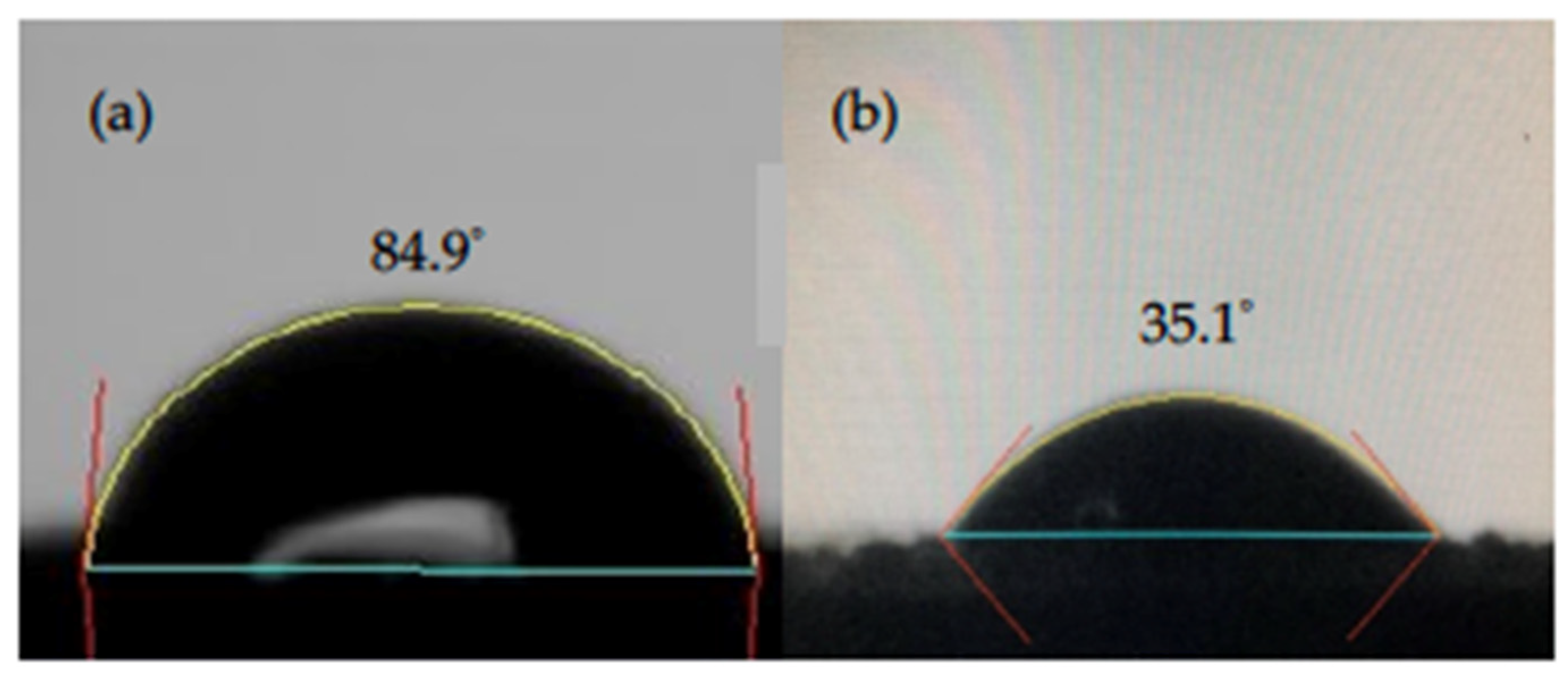
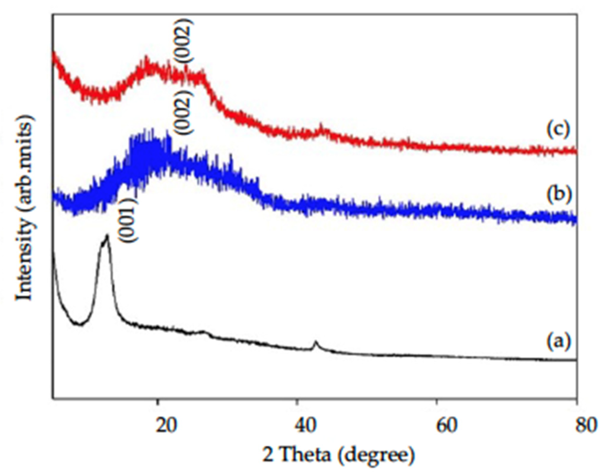
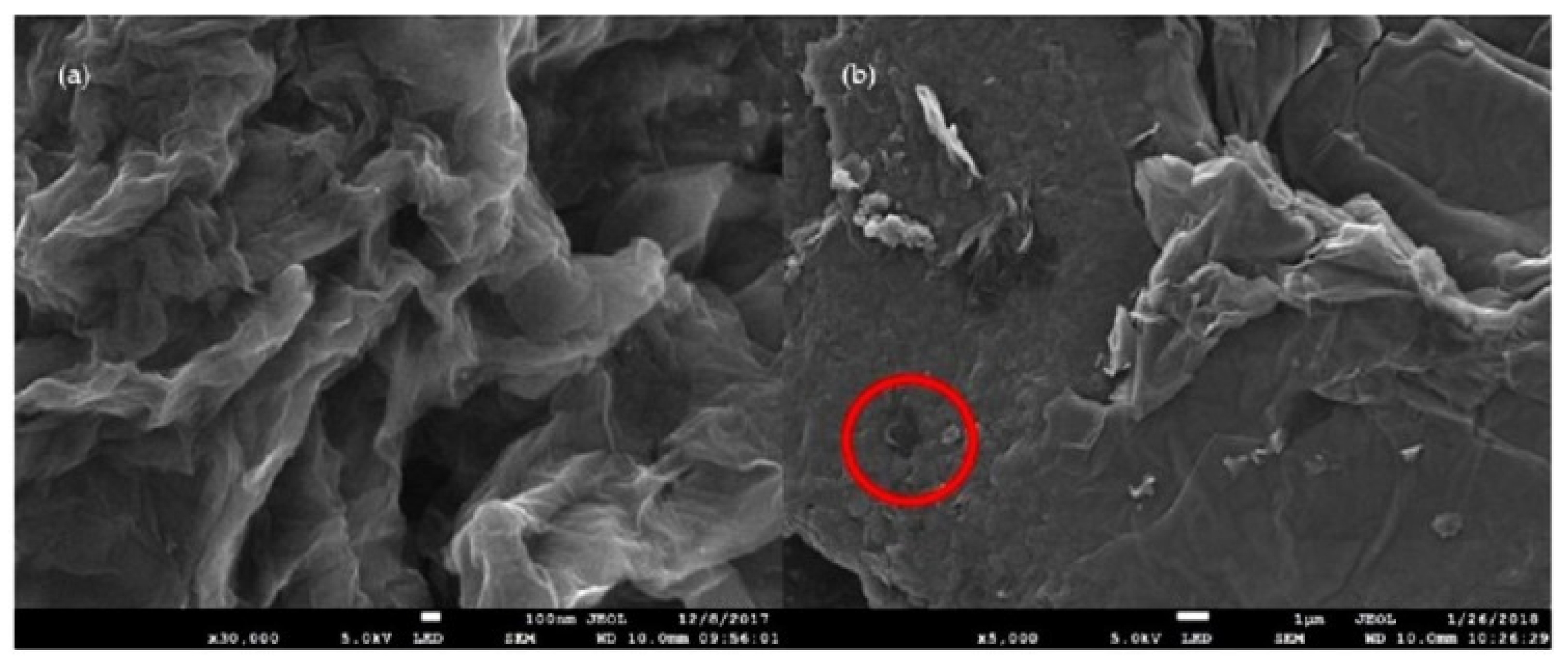
3.1. Physical and Chemical Characterization

XRD patterns of GO, rGO with/without acid modification are shown in Figure 2. Graphene oxide (GO) had a sharp peak between 2θ = 10–12° ((a) in Figure 2), which is the characteristic peak of GO indicating (001) crystalline structure [23]. After reduction with HMTA, the characteristic peak of GO disappeared, followed by a half-rounded convex peak appearing at 2θ = 20–25°, which indicated that an amorphous (002) structure of graphene (rGO) had formed ((b) in Figure 2) [29]. With chemical modification (HNO3:H2SO4 = 2:1), GO became porous graphene oxide firstly and then reduced to rGO with HMTA. XRD patterns of am-rGO ((c) in Figure 2) had similar patterns as those of rGO without acid modification, which indicated the crystalline structure did not change due to acid modification.
The surface morphology of graphene (rGO) with/without acid modification is demonstrated in Figure 3. Graphene without chemical modification (Figure 3a) had a lamellar, wrinkled layered structure, which is consistent with structures reported by other studies [23,30]. The smooth and flower-like topography can be found in rGO without acid modification. After acid treatment and then being reduced to rGO, the surface of rGO was damaged due to the strong acid treatment (Figure 3b). The corrosive strong acids etched the GO surface (as shown in red circle), and made it become a crushed and more porous structure. The uneven surface morphology and etched holes with diameters of 500–800 nm were found on the am-rGO. The unsmooth surface and more porous structure of the acid-modified rGO can provide more ion accessibility, which indicates improving the sorption of ions.
FTIR spectroscopy was further explored to reveal differences in functional groups between rGO with/without chemical modification (Figure 4). The strong peak at 3443 cm−1 represents the hydroxyl groups (C-OH). The -CH2 absorption bands centered at 2921 cm−1 (asymmetric) and 2852 cm−1 (symmetric) assigned to alkyl moieties were only observed in rGO without acid modification. The -C=O stretching vibration of carbonyl groups and -COOH carboxyl group were located at 1632 and 1584 cm−1, respectively [31]. The absorption bands of -C-O (expoxy) and -C-O (alkoxy) at 1220 and 1060 cm−1, respectively, were also identified [18]. The differences in functional groups of acid-modified rGO can be found at 1619, 1339, and 1040 cm−1, which were attributed to aromatic bonds (C=C), NO2 stretching, and sulfonic acid (-SO3H) groups [32], respectively, due to the strong reactions of strong acids (HNO3:H2SO4 = 2:1) on rGO [25].
The wettability of the electrode material is also a key factor affecting the CDI performance. Therefore, we conducted the contact angle measurements to reveal the wettability properties of rGO with/without acid treatment. The water droplet images on rGO with/without acid modification are shown in Figure 5. We found the contact angle was 84.9° on rGO without chemical modification, which indicated the relatively hydrophobic nature of graphene. While for rGO treated with strong acids, the contact angle significantly dropped to 35.1°, which demonstrated hydrophilic property of acid treated rGO (am-rGO).
The improved wettability of rGO due to acid modification is illustrated in FTIR analyses and SEM images. The changes in the functional groups from the contribution of sulfonic acid groups, hydroxyl groups, and NO2 stretching after acid pretreatment resulted in better wettability of rGO [18]. Other factors, such as crushed surfaces and etched holes on rGO, due to the corrosive strong acid reaction found in SEM images, may also explain more hydrophilic property of am-rGO.
The pore volume, pore size, and specific surface area of rGO with/without acid treatment are shown in Table 1. The specific surface area of rGO without acid pretreatment was 12.56 m2/g, and the average pore volume and pore size based on BJH calculation were 0.0219 cm3/g and 6.97 nm, respectively. With acid modification, am-rGO had slightly smaller pore volume (0.0217 cm3/g) with a larger pore size (14.46 nm), but had smaller specific surface area (6.00 m2/g).
The acid modification process did not improve the specific surface area of rGO, but did enlarge average pore size, which was observed in the SEM images with etched holes on rGO. The acid pretreatment process only slightly decreased the Vmeso/Vtot (pore volume of mesopores to pore volume of total pores) from 95.9 to 92.2%. The dominant fractions of pore size with/without acid modification are mesopores, which are beneficial for CDI processes.

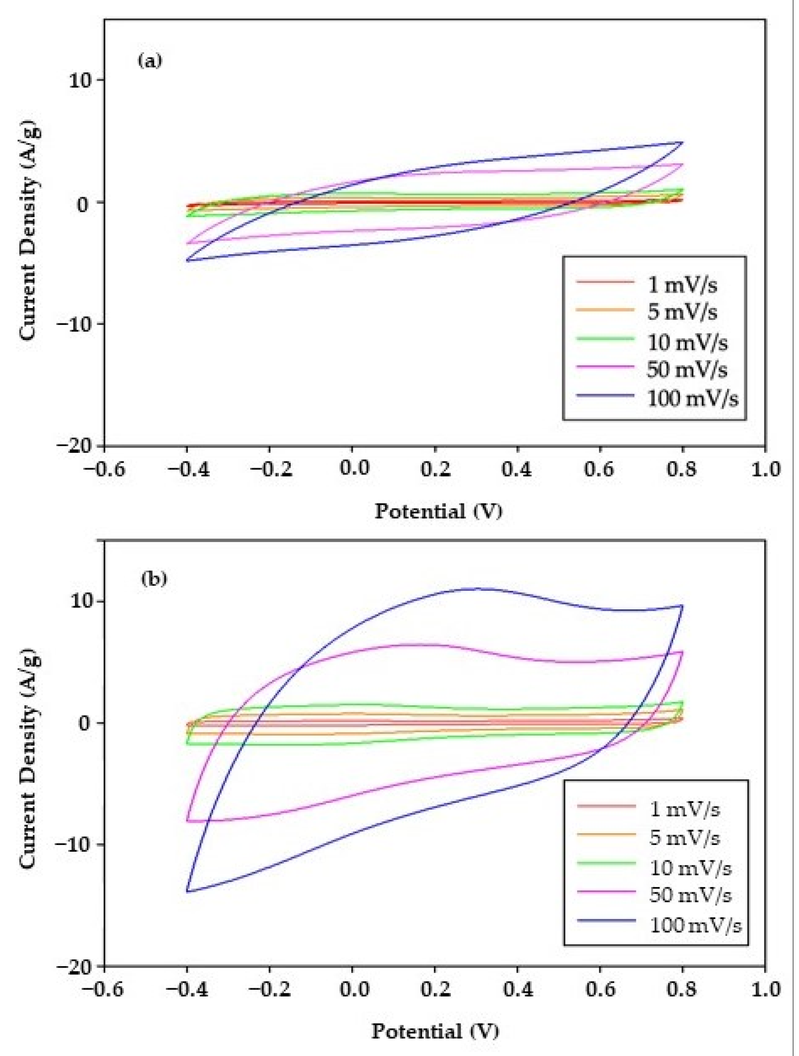
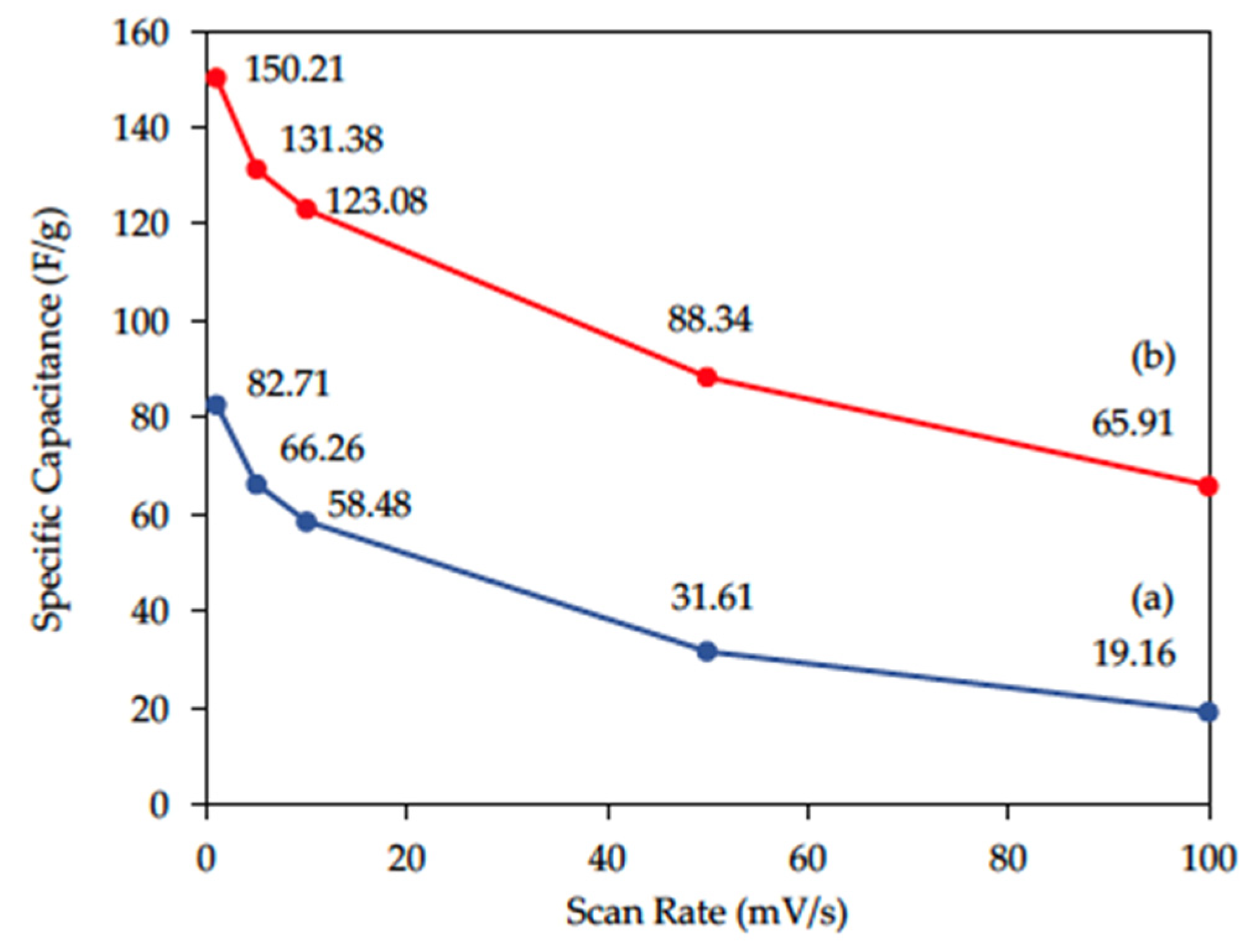
3.2. Electrochemical Properties

Cyclic voltammetry (CV) was conducted to explore the electrochemical properties of rGO with/without acid modification (Figure 6). The CV curves of rGO and am-rGO were symmetric, which indicated both rGO and am-rGO are ideal capacitors. The specific capacitance (F/g) calculated from CV curves is shown in Figure 7. At the same scan rate, am-rGO modified by HNO3:H2SO4 = 2:1 has a larger specific capacitance. For example, at a scan rate of 1 mV/s, the specific capacitance of am-rGO is largest (150.21 F/g) when compared to that of rGO (82.71 F/g). With acid modification, the specific capacitance can be enhanced 1.8 times at the lowest scan rate (1 mV/s), while it can be dramatically increased to 3.4 times at the highest scan rate (100 mV/s). The higher specific capacitance is a good indicator for higher electrosorption capacity.

3.3. CDI Performance

The CDI performances of rGO with/without acid modification were compared in Figure 8 and Table 2. At the applied voltage of 1.0 V, a batch mode CDI was conducted to determine the NaCl removal efficiency and electrosorption capacity of electrode materials. The initial conductivity of NaCl solution was 112.6 µS/cm, corresponding to 50 mg/L NaCl. For rGO without acid pretreatment, the conductivity gradually decreased to 111.1 µS/cm within 3 min, which represented 1.3% removal efficiency and an electrosorption capacity of 0.23 mg NaCl/g electrode (3.97 μmol NaCl/g electrode) in the first cycle. While for electrodes made with am-rGO, the conductivity rapidly dropped to 108 µS/cm within 1 min, which indicated 3.5% removal efficiency, and the corresponding electrosorption capacity was 0.63 mg NaCl/g electrode (10.86 μmol NaCl/g electrode) in the first cycle. The improvement of the electrosorption capacity of am-rGO was due to the addition of sulfonic acid and NO2 functional groups on rGO, which improved the electrochemical properties of rGO and therefore increased the affinity of am-rGO for salt ions.
The regeneration tests were also carried out for three electrosorption/desorption cycles. The am-rGO demonstrated good regeneration performance in the CDI system, which remained stable for three cycles with 3.5% removal efficiency, and an electrosorption capacity of 0.63 mg NaCl/g electrode (10.86 μmol NaCl/g electrode) for each cycle. However, rGO without acid modification showed decreasing removal efficiency and lower electrosorption capacity for the subsequent cycle. For the third cycle, CDI with rGO can only achieve 0.4% NaCl removal efficiency and an electrosorption capacity of 0.07 mg NaCl/g electrode (1.21 μmol NaCl/g electrode).
We found that the average electrosorption capacity of am-rGO was 10.86 μmol NaCl/g am-rGO, which was 3.9 times of that of rGO. The addition of a sulfonic acid group, hydroxyl group, and NO2 stretching on rGO after acid modification significantly improved the electrosorptive capability and stability of rGO. The comparison with graphene synthesized with different methods applied to CDI systems is shown in Table 3. In comparison with previous study [20], even our synthesized am-rGO had relatively low specific surface area (6.0 m2/g); the electrosorption capacity of am-rGO (10.86 μmol NaCl/g am-rGO) was higher than that (6.0 μmol NaCl/g rGO), with a higher specific surface area (222.01 m2/g) at an applied voltage of 1.0 V. The greener reductant (HMTA) was used in this study instead of using toxic hydrazine, which may result in a lower specific surface area of rGO. Trying other green reductants to synthesize rGO for higher specific surface area and more stable characteristics is highly suggested for future studies.

4. Conclusions

Chemical modification with strong acids can significantly improve the wettability and specific capacitance of graphene. The NO2 stretching and sulfonic acid groups were found on rGO after chemical modification by FTIR analyses. The contact angle of rGO notably reduced from 84.9° (rGO) to 35.1° (am-rGO), indicating acid modification dramatically enhanced the wettability of rGO. The specific capacitance of am-rGO was enhanced by 1.8 times at the lowest scan rate (1 mV/s). The CDI performance demonstrated that the average NaCl electrosorption capacity can be improved 3.9 times when applying am-rGO as electrode material. This work illustrates that chemically modified rGO has great potential for application in CDI processes, and reduction processes with other greener reducing agent can be further developed for a higher specific surface area of graphene.

Author Contributions

Conceptualization, C.-Y.P. and Y.-F.C.; methodology, Y.-F.C. and C.-Y.W.; validation, Y.-F.C. and C.-Y.W.; data curation, Y.-F.C. and C.-Y.W.; writing—original draft preparation, Y.-F.C.; writing—review and editing, C.-Y.P. and Y.-F.C.; visualization, C.-Y.P. and Y.-F.C.; supervision, C.-Y.P.; funding acquisition, C.-Y.P. All authors have read and agreed to the published version of the manuscript.

Funding

This research was funded by the Taiwan Ministry of Science and Technology (MOST 106-2621-M-032-001-MY1).

Acknowledgments

The advices of electrochemical analyses from Cheng-Lan Lin in the Department of Chemical and Materials Engineering, Tamkang University, Taiwan is gratefully acknowledged.

Conflicts of Interest

The authors declare no conflict of interest.

References

  1. Sher, F.; Iqbal, S.Z.; Rasheed, T.; Hanif, K.; Sulejmanović, J.; Zafar, F.; Lima, E.C. Coupling of electrocoagulation and powder activated carbon for the treatment of sustainable wastewater. Environ. Sci. Pollut. Res. 2021, 28, 48505–48516. [Google Scholar] [CrossRef] [PubMed]
  2. Rasheed, T.; Rizwan, K.; Bilal, M.; Sher, F.; Iqbal, H.M.N. Tailored functional materials as robust candidates to mitigate pesticides in aqueous matrices—A review. Chemosphere 2021, 282, 131056. [Google Scholar] [CrossRef] [PubMed]
  3. Rasheed, T.; Kausar, F.; Rizwan, K.; Adeel, M.; Sher, F.; Alwadai, N.; Alshammari, F.H. Two dimensional MXenes as emerging paradigm for adsorptive removal of toxic metallic pollutants from wastewater. Chemosphere 2022, 287, 132319. [Google Scholar] [CrossRef] [PubMed]
  4. Sulejmanović, J.; Kovač, N.; Memić, M.; Šabanović, E.; Begić, S.; Sher, F. Selective removal of lead ions from aqueous solutions using SiO2–MoO3: Isotherm, kinetics and thermodynamic studies. Case Stud. Chem. Environ. Eng. 2021, 3, 100083. [Google Scholar] [CrossRef]
  5. El Messaoudi, N.; El Khomri, M.; Ablouh, E.-H.; Bouich, A.; Lacherai, A.; Jada, A.; Lima, E.C.; Sher, F. Biosynthesis of SiO2 nanoparticles using extract of Nerium oleander leaves for the removal of tetracycline antibiotic. Chemosphere 2022, 287, 132453. [Google Scholar] [CrossRef]
  6. Américo-Pinheiro, J.H.P.; Paschoa, C.V.M.; Salomão, G.R.; Cruz, I.A.; Isique, W.D.; Ferreira, L.F.R.; Sher, F.; Torres, N.H.; Kumar, V.; Pinheiro, R.S.B. Adsorptive remediation of naproxen from water using in-house developed hybrid material functionalized with iron oxide. Chemosphere 2022, 289, 133222. [Google Scholar] [CrossRef]
  7. AlMarzooqi, F.A.; Al Ghaferi, A.A.; Saadat, I.; Hilal, N. Application of capacitive deionisation in water desalination: A review. Desalination 2014, 342, 3–15. [Google Scholar] [CrossRef]
  8. Anderson, M.A.; Cudero, A.L.; Palma, J. Capacitive deionization as an electrochemical means of saving energy and delivering clean water. Comparison to present desalination practices: Will it compete? Electrochim. Acta 2010, 55, 3845–3856. [Google Scholar] [CrossRef]
  9. Myint, M.T.Z.; Al-Harthi, S.H.; Dutta, J. Brackish water desalination by capacitive deionization using zinc oxide micro/nanostructures grafted on activated carbon cloth electrodes. Desalination 2014, 344, 236–242. [Google Scholar] [CrossRef]
  10. Huang, W.; Zhang, Y.; Bao, S.; Cruz, R.; Song, S. Desalination by capacitive deionization process using nitric acid-modified activated carbon as the electrodes. Desalination 2014, 340, 67–72. [Google Scholar] [CrossRef]
  11. Seo, S.-J.; Jeon, H.; Lee, J.K.; Kim, G.-Y.; Park, D.; Nojima, H.; Lee, J.; Moon, S.-H. Investigation on removal of hardness ions by capacitive deionization (CDI) for water softening applications. Water Res. 2010, 44, 2267–2275. [Google Scholar] [CrossRef] [PubMed]
  12. Hu, C.; Liu, F.; Lan, H.; Liu, H.; Qu, J. Preparation of a manganese dioxide/carbon fiber electrode for electrosorptive removal of copper ions from water. J. Colloid Interface Sci. 2015, 446, 359–365. [Google Scholar] [CrossRef] [PubMed]
  13. Kim, Y.-J.; Choi, J.-H. Enhanced desalination efficiency in capacitive deionization with an ion-selective membrane. Sep. Purif. Technol. 2010, 71, 70–75. [Google Scholar] [CrossRef]
  14. Biesheuvel, P.M.; Zhao, R.; Porada, S.; van der Wal, A. Theory of membrane capacitive deionization including the effect of the electrode pore space. J. Colloid Interface Sci. 2011, 360, 239–248. [Google Scholar] [CrossRef] [Green Version]
  15. Farmer, J.C.; Fix, D.V.; Mack, G.V.; Pekala, R.W.; Poco, J.F. Capacitive deionization of NaCl and NaNO3 solutions with carbon aerogel electrodes. J. Electrochem. Soc. 1996, 143, 159–169. [Google Scholar] [CrossRef]
  16. Peng, Z.; Zhang, D.; Shi, L.; Yan, T. High performance ordered mesoporous carbon/carbon nanotube composite electrodes for capacitive deionization. J. Mater. Chem. 2012, 22, 6603–6612. [Google Scholar] [CrossRef]
  17. Zhang, D.; Yan, T.; Shi, L.; Peng, Z.; Wen, X.; Zhang, J. Enhanced capacitive deionization performance of graphene/carbon nanotube composites. J. Mater. Chem. 2012, 22, 14696–14704. [Google Scholar] [CrossRef]
  18. Jia, B.; Zou, L. Wettability and its influence on graphene nansoheets as electrode material for capacitive deionization. Chem. Phys. Lett. 2012, 548, 23–28. [Google Scholar] [CrossRef]
  19. Bharath, G.; Alhseinat, E.; Ponpandian, N.; Khan, M.A.; Siddiqui, M.R.; Ahmed, F.; Alsharaeh, E.H. Development of adsorption and electrosorption techniques for removal of organic and inorganic pollutants from wastewater using novel magnetite/porous graphene-based nanocomposites. Sep. Purif. Technol. 2017, 188, 206–218. [Google Scholar] [CrossRef]
  20. Li, H.; Zou, L.; Pan, L.; Sun, Z. Novel graphene-like electrodes for capacitive deionization. Environ. Sci. Technol. 2010, 44, 8692–8697. [Google Scholar] [CrossRef]
  21. Li, H.; Lu, T.; Pan, L.; Zhang, Y.; Sun, Z. Electrosorption behavior of graphene in NaCl solutions. J. Mater. Chem. 2009, 19, 6773–6779. [Google Scholar] [CrossRef]
  22. Hummers, W.S., Jr.; Offeman, R.E. Preparation of graphitic oxide. J. Am. Chem. Soc. 1958, 80, 1339. [Google Scholar] [CrossRef]
  23. Sakthivel, T.; Gunasekaran, V.; Kim, S.-J. Effect of oxygenated functional groups on the photoluminescence properties of graphene-oxide nanosheets. Mater. Sci. Semicond. Process. 2014, 19, 174–178. [Google Scholar] [CrossRef]
  24. Huang, S.-Y.; Fan, C.-S.; Hou, C.-H. Electro-enhanced removal of copper ions from aqueous solutions by capacitive deionization. J. Hazard. Mater. 2014, 278, 8–15. [Google Scholar] [CrossRef]
  25. Zhou, T.; Chen, F.; Liu, K.; Deng, H.; Zhang, Q.; Feng, J.; Fu, Q. A simple and efficient method to prepare graphene by reduction of graphite oxide with sodium hydrosulfite. Nanotechnology 2010, 22, 045704. [Google Scholar] [CrossRef]
  26. Teixeira, R.A.; Lima, E.C.; Benetti, A.D.; Thue, P.S.; Cunha, M.R.; Cimirro, N.F.; Sher, F.; Dehghani, M.H.; dos Reis, G.S.; Dotto, G.L. Preparation of hybrids of wood sawdust with 3-aminopropyl-triethoxysilane. Application as an adsorbent to remove Reactive Blue 4 dye from wastewater effluents. J. Taiwan Inst. Chem. Eng. 2021, 125, 141–152. [Google Scholar] [CrossRef]
  27. Skoog, D.A.; Holler, F.J.; Crouch, S.R. Principles of Instrumental Analysis; Cengage Learning: Boston, MA, USA, 2017. [Google Scholar]
  28. Chen, Z.; Zhang, H.; Wu, C.; Wang, Y.; Li, W. A study of electrosorption selectivity of anions by activated carbon electrodes in capacitive deionization. Desalination 2015, 369, 46–50. [Google Scholar] [CrossRef]
  29. El Deen, A.G.; Barakat, N.; Khalil, K.A.; Motlak, M.; Kim, H.Y. Graphene/SnO2 nanocomposite as an effective electrode material for saline water desalination using capacitive deionization. Ceram. Int. 2014, 40, 14627–14634. [Google Scholar] [CrossRef]
  30. Xu, X.; Pan, L.; Liu, Y.; Lu, T.; Sun, Z. Enhanced capacitive deionization performance of graphene by nitrogen doping. J. Colloid Interface Sci. 2015, 445, 143–150. [Google Scholar] [CrossRef]
  31. Gupta, B.; Kumar, N.; Panda, K.; Kanan, V.; Joshi, S.; Visoly-Fisher, I. Role of oxygen functional groups in reduced graphene oxide for lubrication. Sci. Rep. 2017, 7, 45030. [Google Scholar] [CrossRef]
  32. Si, Y.; Samulski, E.T. Synthesis of water soluble graphene. Nano Lett. 2008, 8, 1679–1682. [Google Scholar] [CrossRef] [PubMed]
Figure 1. Schematic diagram of the CDI system.
Water 14 01379 g001
Figure 2. XRD patterns of (a) GO, (b) rGO, and (c) am-rGO.
Water 14 01379 g002
Figure 3. FE-SEM images of (a) rGO and (b) am-rGO.
Water 14 01379 g003
Figure 4. FTIR spectra of (a) rGO and (b) am-rGO.
Water 14 01379 g004
Figure 5. Contact angle images of (a) rGO and (b) am-rGO.
Water 14 01379 g005
Figure 6. Cyclic voltammograms (CV) of (a) rGO and (b) am-rGO at various scan rates.
Water 14 01379 g006
Figure 7. Mass normalized specific capacitance of (a) rGO and (b) am-rGO with respect to the scan rates.
Water 14 01379 g007
Figure 8. Electrosorption/desorption profiles of the (a) rGO and (b) am-rGO electrode in 50 mg/L NaCl (1.0 V).
Water 14 01379 g008
Table 1. Surface and pore characteristics of rGO and am-rGO.
SamplePore Volume
(Vtot)(cm3/g)
Pore Size
(nm)
BET Surface Area
(m2/g)
Vmicro a
(cm3/g)
Vmeso b
(cm3/g)
Vmeso/Vtot
(%)
rGO0.02196.9712.560.00090.02195.9
am-rGO0.021714.466.000.00170.02092.2
a: t-Plot micropore volume. b: t-Plot mesopore volume.
Table 2. Removal efficiency and electrosorption capacity of the rGO and am-rGO electrode in 50 mg/L NaCl (1.0V).
CDI
Cycle
rGOam-rGO
Removal Efficiency (%)Electrosorption CapacityRemoval Efficiency (%)Electrosorption Capacity
mg NaCl/gμmol NaCl/gmg NaCl/gμmol NaCl/g
11.30.233.973.50.6310.86
21.00.183.103.50.6310.86
30.40.071.213.50.6310.86
Average0.850.162.763.50.6310.86
Table 3. Comparison with graphene electrode materials applied in CDI processes.
SampleBET Surface Area
(m2/g)
Pore Volume
(cm3/g)
Pore Size
(nm)
Reducing Agent[NaCl]
(mg/L)
Applied Voltage (V)Electrosorption Capacity
(μmol NaCl/g)
Ref
PG 1154.70.87-N2(g) annealing2001.865.8[30]
NG 2358.91.02-NH3(g) annealing2001.882.2[30]
GNC 3299-3.6Fe powder2502.070.1[18]
S-GNC 4464-3.3Fe powder2502.0147.0[18]
rGO14.2-7.42hydrazine962.031.6[21]
GNF 5222.0151.01-hydrazine252.023.2[20]
251.06.0[20]
rGO12.560.02196.97HMTA501.02.76This work
am-rGO6.000.021714.46HMTA501.010.86This work
1 Pristine graphene (PG) with N2(g) annealing at 800 °C. 2 Nitrogen-doped graphene (NG) with NH3(g) annealing at 800 °C. 3 Graphene nanosheets (GNS). 4 Sulfonated graphene nanosheets (S-GNC). 5 Graphene-like nanoflakes (GNFs).
Publisher’s Note: MDPI stays neutral with regard to jurisdictional claims in published maps and institutional affiliations.

