

Laboratory and Numerical Investigation of Pre-Tensioned Reinforced Concrete Railway Sleepers Combined with Plastic Fiber Reinforcement

 ,
,  , ,
, ,  ,
,  , , ,
, , ,  , ,
, ,  add
Show full author list
add
Show full author list
Abstract
1. Introduction
1.1. General Introduction
1.2. Railway Sleepers
1.3. Identification of the Research Gap and the Structure of the Current Paper
2. Materials and Methods
2.1. Materials
2.1.1. Details of the Pre-Stressed Sleeper
2.1.2. Compressive Strength of Cylinder Samples
- RTV reference, compressive strength after storage in water.
- RT reference, compressive strength after storage in air.
- STV synthetic fiber-reinforced, compressive strength after storage in water.
- ST synthetic fiber-reinforced, compressive strength after storage in air.
2.1.3. Splitting-Tensile Strength of Cylinder Samples
- RBV reference, splitting-tensile strength after storage in water.
- RB reference, splitting-tensile strength after storage in air.
- SBV synthetic fiber-reinforced, splitting-tensile strength after storage in water
- SB synthetic fiber-reinforced, splitting-tensile strength after storage in air.
2.2. Methods
2.2.1. GOM Aramis DIC Measurement System
2.2.2. List of Devices Used for Structural Testing in the Laboratory
2.2.3. Static Structural Tests of Sleepers
- 1
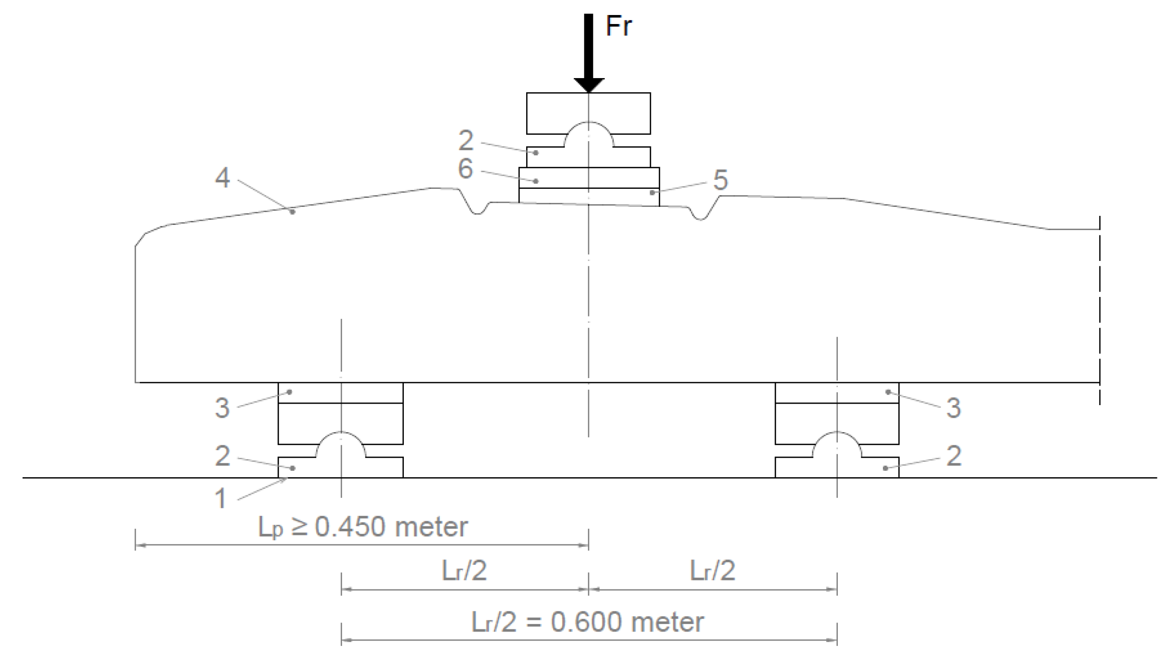
- Examination of the cross-section under the rail in the installation position (loading the under-rail cross-section for a positive moment) in accordance with standard MSZ EN 13230-2 [56].
- 2
- Examination of the central cross-section of the sleeper in an inverted position for a negative moment (static loading for a negative moment. Sleeper center (inverted position)) in accordance with standard Section 4.1.3 of MSZ EN 13230-2 [56].
- 3
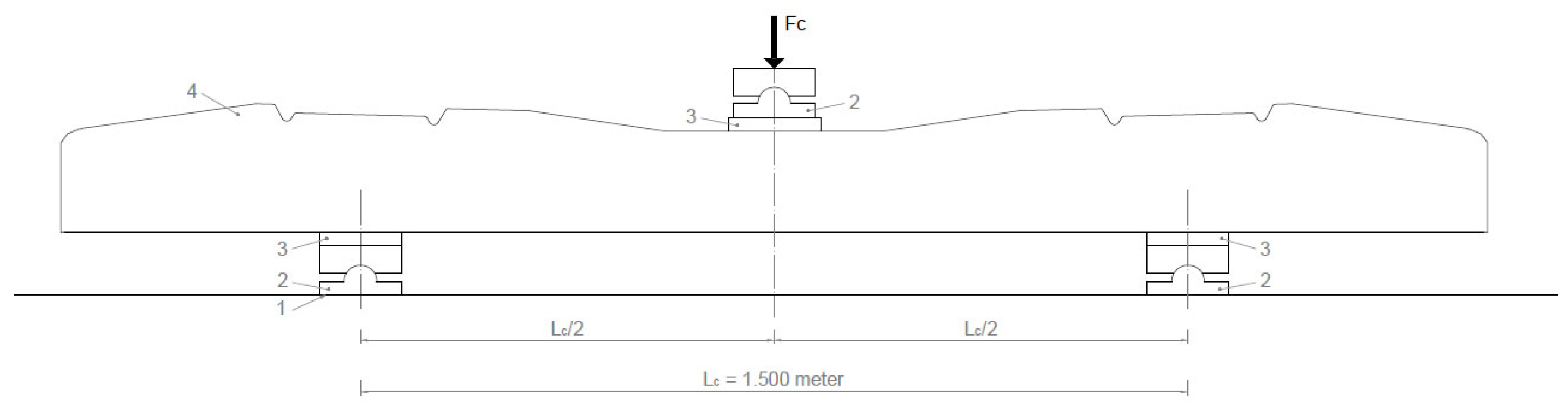
- Examination of the central cross-section of the sleeper in the normal position for a positive moment (static loading for a positive moment, sleeper center).
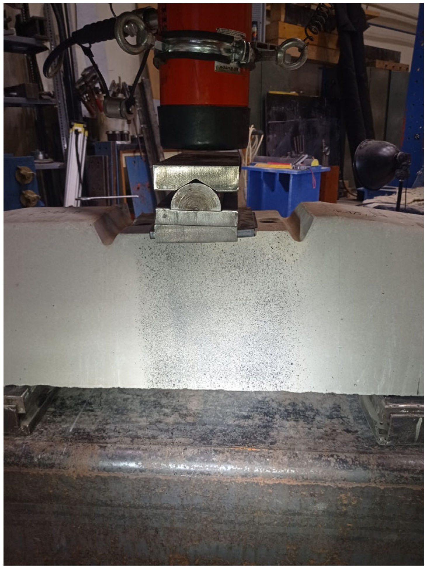
Examination of the Cross-Section under the Rail in the Installation Position
- Fro value given by the manufacturer based on the required load-bearing capacity;
- Frr the force value that causes the first crack;
- Fr0.10 the force value causing a crack width of 0.1 mm;
- Fr0.05 force value causing a crack width of 0.05 mm remaining after unloading;
- FrB a force value that can no longer be increased (causing breakage).
Examination of the Central Cross-Section of the Sleeper in an Inverted Position for a Negative Moment
- Fcon value given by the manufacturer based on the required load-bearing capacity;
- Fcrn the force value that causes the first crack;
- Fc0.10n the force value causing a crack width of 0.1 mm;
- Fc0.05n force value causing a crack width of 0.05 mm remaining after unloading;
- FcBn a force value that can no longer be increased (causing breakage).
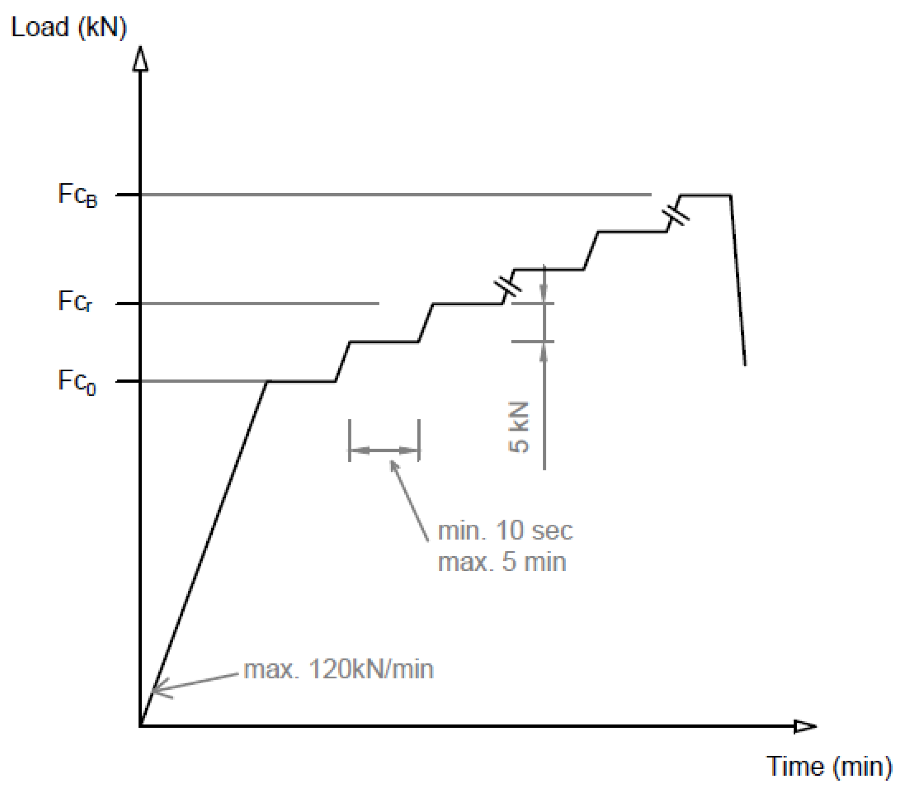
Examination of the Central Cross-Section of the Sleeper in the Normal Position for a Positive Moment
- Fc0 value given by the manufacturer based on the required load-bearing capacity;
- Fcr the force value that causes the first crack;
- Fc0.10 the force value causing a crack width of 0.1 mm;
- Fc0.05 force value causing a crack width of 0.05 mm remaining after unloading;
- FcB a force value that can no longer be increased (causing breakage).
2.2.4. FE Modeling
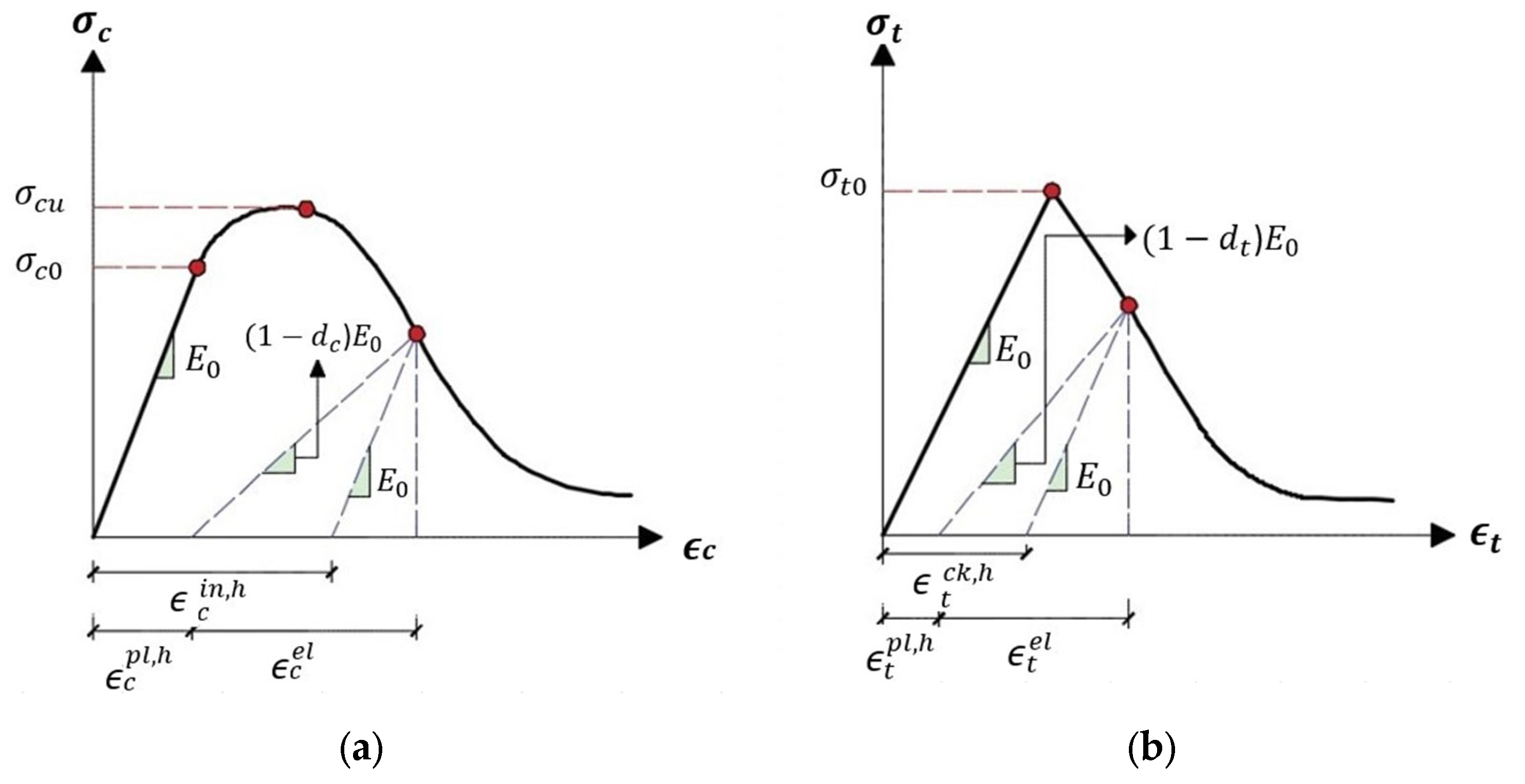
Concrete Damage Plasticity Constitutive Model (CDM)
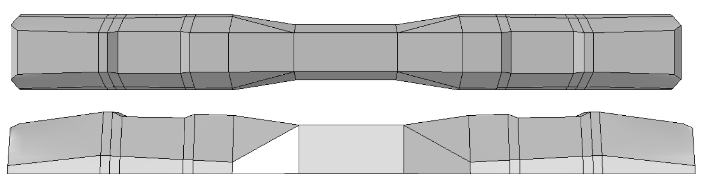
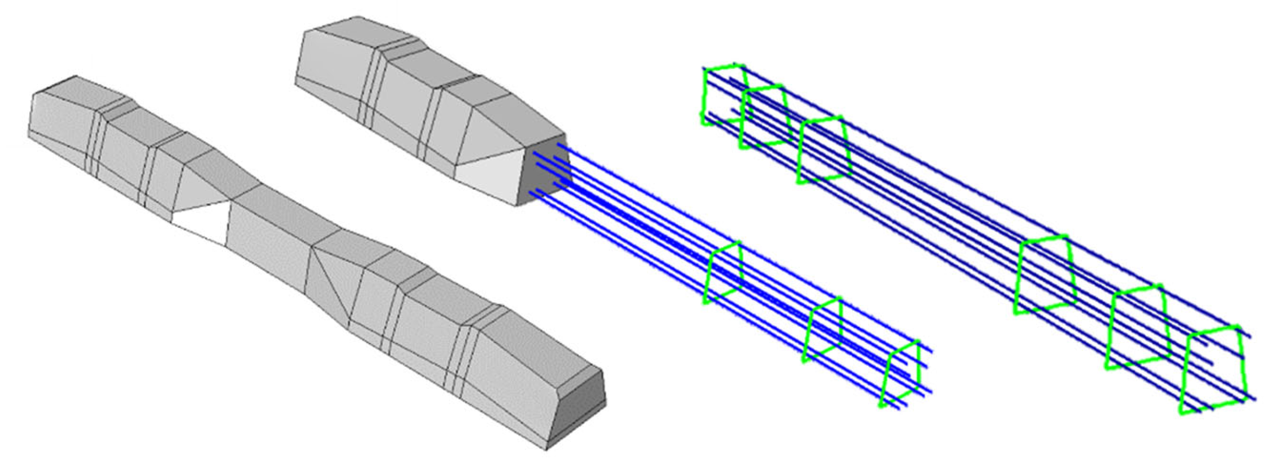
Numerical Modeling of the Sleeper by ABAQUS FE Software
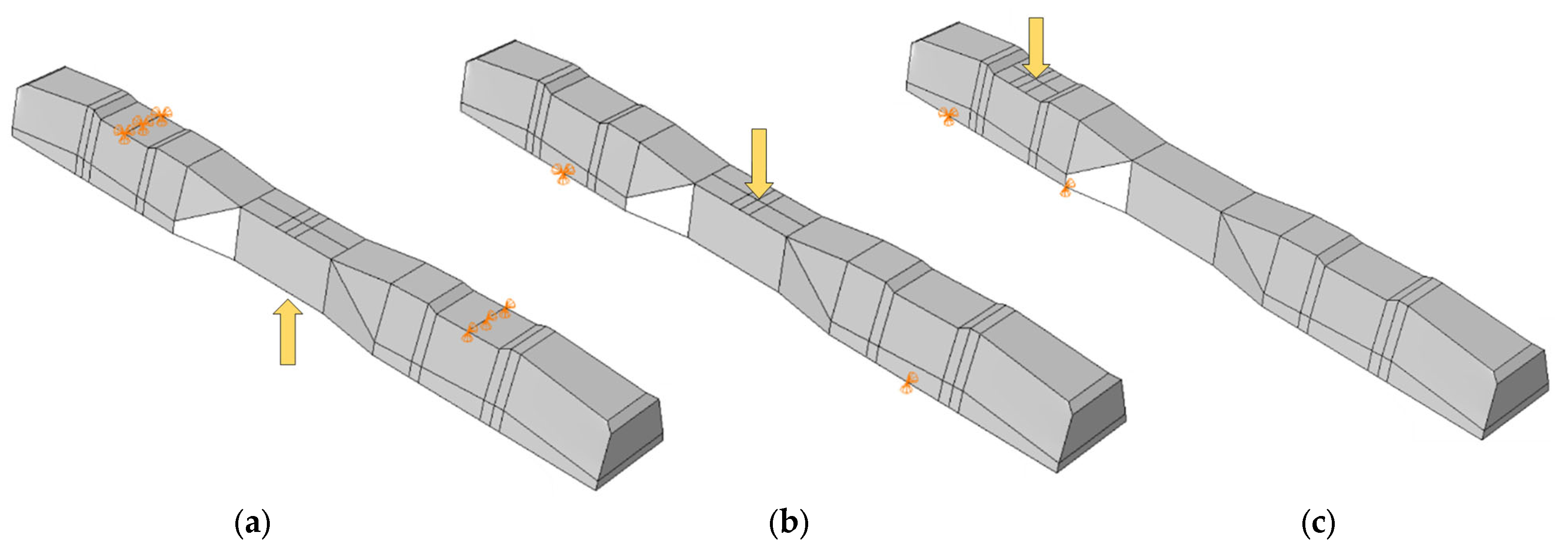
- R and S specimens correspond to models subjected to rail base plate loading with and without fibers, respectively.
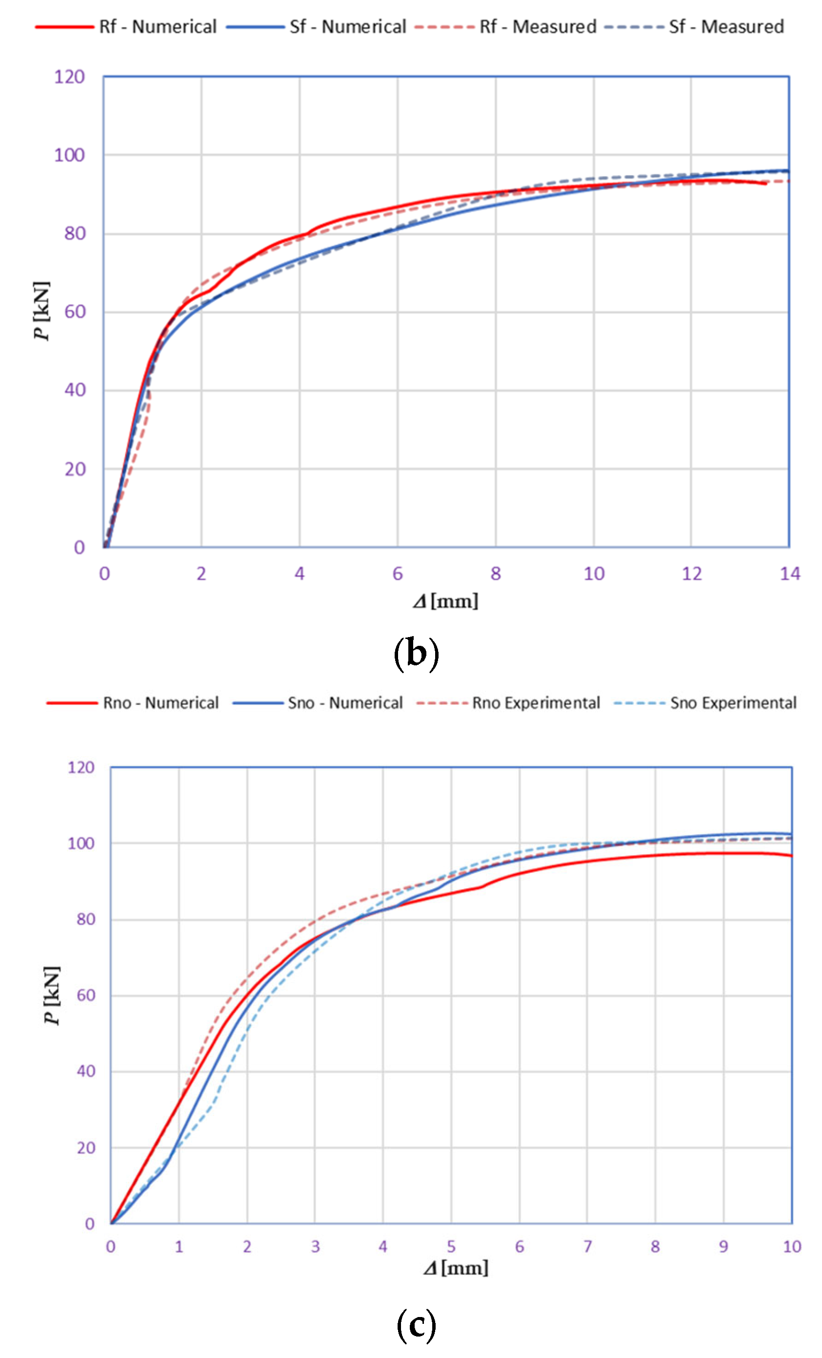
- Rf and Sf are specimens subject to mid-span upward loading, with and without fibers.
- Rno and Sno are specimens subjected to mid-span downward loading, with and without fibers.
3. Results and Discussion
3.1. Laboratory Tests
3.1.1. Examination of the Cross-Section under the Rail in the Installation Position (Rail Base Plate Loading Case)
Compliance Criteria
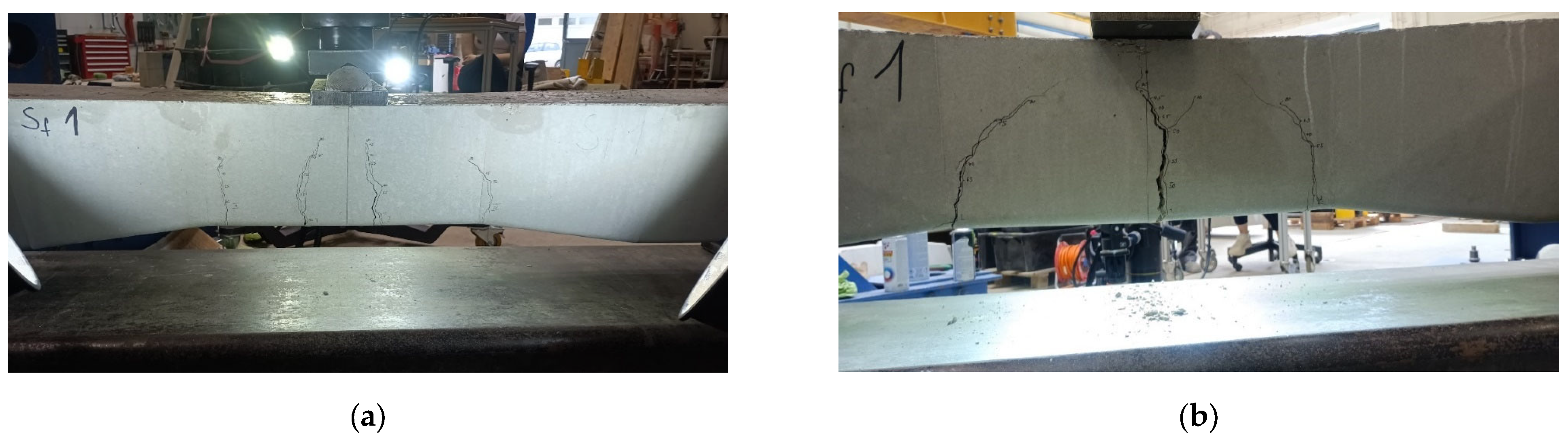
3.1.2. Examination of the Central Cross-Section of the Sleeper in an Inverted Position for a Negative Moment (Mid-Span Upward Loading Case)
Compliance Criteria
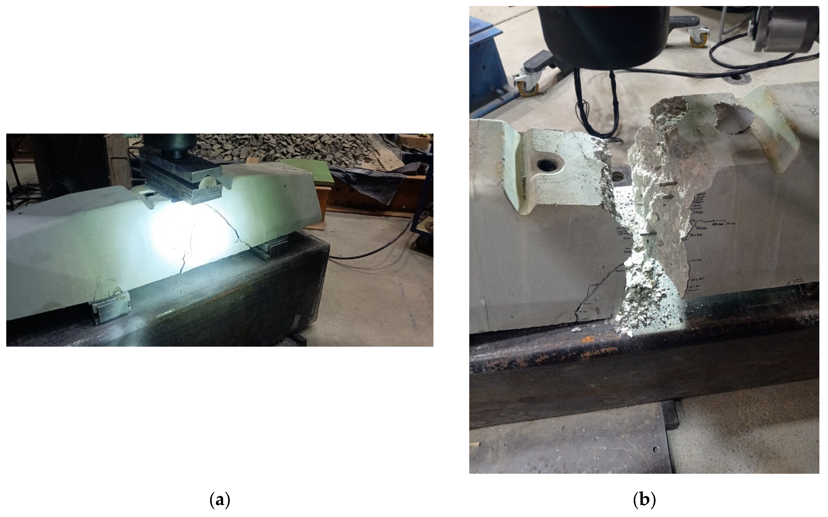
3.1.3. Examination of the Central Cross-Section of the Sleeper in the Normal Position for a Positive Moment (Mid-Span Downward Loading Case)
Compliance Criteria
3.2. FE Modeling
3.2.1. Calibration Process
3.2.2. Results of FE Modeling
3.3. Further Discussion
3.3.1. General Topics
3.3.2. Specific Topics
- There were cases where fibers were twisted/turned into cracks during/before load removal, but the cracks did not close after load removal;
- The real deflection (vertical displacement) values were compared with the results obtained from numerical modeling;
- In the DIC measurements, the surface area was 100 × 100 mm (or 150 × 150 mm), which showed only a small area of failure. This proved to be a good solution for the cross-section below the rail; however, in the case of loading the middle cross-section up to failure, the cracks appearing in the load “lower pulled-bended area” could not be examined.
- The examination of crack development in pre-stressed concrete railway sleepers reinforced with plastic fibers revealed detailed insights. During load application, cracks first appeared at force values of 45 kN, monitored continuously using DIC technology. The inclusion of plastic fibers significantly reduced crack width and promoted a more confined crack pattern compared to traditional sleepers. For instance, at a force value of 95.2 kN, the plastic fiber-reinforced specimens exhibited less severe cracks, demonstrating their enhanced crack resistance and limited crack propagation. Additionally, the crack width at 0.05 mm remained after unloading at a force of 275 kN for fiber-reinforced sleepers, compared to 320 kN for non-reinforced ones, indicating an improvement in crack control. This crack management significantly contributes to the overall structural integrity and longevity of railway sleepers, highlighting the effectiveness of plastic fiber reinforcement in reducing maintenance needs and extending service life.
- In the case of bending tests of the sleepers with the examination of the cross-section under the rail in the installation position (rail base plate loading case), see Section 3.1.1. The regular (reference) sleepers provided 436.39 kN, while the synthetic-reinforced ones provided 433.83 kN load-bearing capacity considering the average static vertical force values according to the test setup. Comparing the synthetic-reinforced specimens with the regular (reference) ones, there was a –0.6% difference. This means that the plastic reinforcing fibers slightly reduced the reference load-bearing capacity. Interestingly, there was a −6.3% reduction in the Frr values on average (175.0 kN for R specimens and 164.0 kN for S specimens, respectively), while comparing Fr0.10 and Fr0.05 values, these differences were +11.6% and −14.1%, respectively. There were no differences between the other results (values) according to the measurements.
- In the case of bending tests of the sleepers with the examination of the central cross-section of the sleeper in an inverted position for a negative moment (mid-span upward loading case), see Section 3.1.2. The regular (reference) sleeper provided 95.2 kN, while the synthetic-reinforced one 97.7 kN load-bearing capacity, considering the average static vertical force values according to the test setup. It was a +2.6% improvement with the synthetic reinforcement. Comparing the Fc0.05n values, there was a –14.3% reduction (70.0 kN for the R specimen and 60.0 kN for the S specimen, respectively). There were no differences between the other results (values) according to the measurements.
- In the case of bending tests of the sleepers with the examination of the central cross-section of the sleeper in the normal position for a positive moment (mid-span downward loading case), see Section 3.1.3. The regular (reference) sleeper provided 106.0 kN, while the synthetic-reinforced one had a 111.6 kN load-bearing capacity, considering the average static vertical force values according to the test setup. It was a +5.3% improvement with the synthetic reinforcement. Comparing the Fc0.05 values, there was a +33.3% increase (60.0 kN for the R specimen and 80.0 kN for the S specimen, respectively). In the case of Fcr, the improvement was +9.1% (55.0 kN for the R specimen and 60.0 kN for the S specimen). There were no differences between the other results (values) according to the measurements.
- The authors were able to calibrate the FE models (see Section 3.2.1) with a maximum of ±2–5% differences compared to the real experiments conducted in the laboratory (see Section 3.1). The primary calibration process was based on the vertical deflection values measured using the GOM Aramis DIC system.
- Based on the vertical deflection results (see Section 3.2.1), there was a clear result that the specimens reinforced by plastic fibers provided an improvement compared to the regular (reference) types (i.e., without additional plastic fiber reinforcement). Parallel with these results, in the case of bending tests of the sleepers with the examination of the central cross-section of the sleeper in an inverted position for a negative moment (mid-span upward loading case) until 50–55 kN, there was no significant difference, while between this value and approximately 92 kN, the S specimen was worse than the R specimen (the maximal vertical deflection difference was approximately 50%, 6.0 mm compared to 4.0 mm). At approximately 92 kN, there was an “inflection point”, and above 92.0 kN, a slight improvement was observed. In the case of bending tests of the sleepers with the examination of the central cross-section of the sleeper in a normal position for a positive moment (mid-span downward loading case), the inflection point was at approximately 80 kN, i.e., below this value, the S specimen provided lower vertical deflections than the R specimens; hence, above it, the result was the opposite. Below 80 kN, the difference was not significant; however, between 80 kN and the ultimate load, the difference was enormous.
- Section 3.2.2 contains the details related to the FE analysis, and every small detail can be checked synchronously with the DIC measurements.
- Based on the above results, and without long-term field tests, the examined plastic fiber-reinforced sleepers cannot be unequivocally recommended; however, they sometimes improve the load-bearing capacity values and the vertical deflections. More detailed investigations are needed in the future.
4. Conclusions
- The current study represents a significant advancement in understanding and using additional plastic fiber reinforcement in manufacturing pre-tensioned reinforced concrete railway sleepers, showing notable progress in railway infrastructure technology.
- Through detailed experimental and numerical analysis, including sophisticated finite element modeling in ABAQUS and comparisons with lab results, this study highlights the structural advantages and resilience that plastic fibers add to concrete sleepers, while also pointing out the complexity and varying impacts of this type of reinforcement.
- The research delves into how these fibers behave under and after stress, uncovering instances where fibers bend or twist into cracks but fail to return to their original shape once the stress is removed. This reveals a complex relationship between the fibers’ assumed orientation and the concrete’s integrity when under pressure.
- The study closely compares actual deflection measurements to those predicted by numerical models using the Digital Image Correlation (DIC) method for accurate vertical displacement measurements. This approach, which focuses on specific surface areas, was effective in identifying failure modes, particularly in crucial sections beneath rail bases, although it did reveal some limitations in tracking crack development under certain stress conditions.
- In terms of quantitative analysis, the research provides an in-depth look at how reinforced sleepers perform under various loads. For example, in bending tests at the rail cross-section, sleepers reinforced with synthetic fibers showed a slight reduction in load-bearing capacity of 0.6% compared to standard sleepers, suggesting a minor decrease in load-bearing ability. However, this was accompanied by exciting findings in reducing and improving specific force resistance values, indicating that while the overall capacity slightly diminished, the performance under certain stresses could actually improve.
- The study also examined different loading scenarios according to related standards, like mid-span upward and downward loading cases, and found improvements in load-bearing capacity with synthetic reinforcement by 2.6% and 5.3%, respectively. These scenarios also showcased variances in vertical deflection performance, with reinforced sleepers displaying both enhancements and decreases in deflection resistance at various stages of loading, highlighting the intricate performance traits of these materials under different structural stresses.
- The accuracy of the Finite Element (FE) models, calibrated to within a 2–5% difference from actual lab experiments, showcases the precision of the simulation techniques used. This calibration, primarily based on vertical deflection measurements taken by the GOM Aramis DIC system, provides a valuable tool for predicting sleeper performance under a range of conditions. However, it also emphasizes the need for more detailed studies and long-term field tests before recommending the widespread use of plastic fiber-reinforced sleepers.
- This thorough study significantly contributes to the field of civil engineering materials science and opens the door to more sustainable and resilient railway infrastructure solutions. By incorporating innovative materials like plastic fibers into the design of railway sleepers, the research underlines a dedication to improving durability and efficiency, establishing a new benchmark for railway construction and maintenance. Although the findings are encouraging, they underscore the essential role of material science and engineering in meeting modern challenges and driving forward technological advances in the railway industry.
- The authors conclude that, based on the presented results and without long-term field tests, the examined plastic fiber-reinforced sleepers cannot be unequivocally recommended. However, they sometimes improve load-bearing capacity values and vertical deflections. More detailed investigations are needed in the future.
Author Contributions
Funding
Data Availability Statement
Conflicts of Interest
Abbreviations
| 3PBT | Three-Point Bending Test |
| ABAQUS | A sophisticated software based on finite element method calculation which is mainly used for research and development |
| ANSYS | A sophisticated software based on finite element method calculation which is mainly used for research and development |
| CDM | Concrete Damage Plasticity Constitutive Model |
| CDP | Concrete Damage Plasticity |
| CF | Carbon Fibers |
| CFRP | Carbon Fiber Reinforced Polymer |
| CFRPC | Carbon Fiber Reinforced Polymer Concrete |
| CNF | Carbon Nanofibers |
| CNT | Carbon Nanotubes |
| DEM | Discrete Element Method |
| DIC | Digital Image Correlation |
| DOF | Degree of Freedom |
| FE | Finite Element |
| FEM | Finite Element Method or Finite Element Modeling |
| FFU | Fiber-Reinforced Foamed Urethane |
| FRF | Frequency Response Function |
| FRP | Fiber Reinforced Plastic or Fiber Reinforced Polymer |
| FRP-OF | Fiber Reinforced Polymer-Optical Fiber |
| GFRP | Glass Fiber Reinforced Polymer |
| GGBFS | Ground Granulated Blast Furnace Slag |
| HPSCC | High-Performance Self-Compacting Concrete |
| L-CFRPU | Laminated Carbon Fiber Reinforced Polyurethane |
| MSFRC | Macro-Synthetic Fiber Reinforced Concrete |
| PC | Polymer Concrete |
| PGRS | Pre-stressed Geopolymer Railway Sleepers |
| PPF | Polypropylene Fiber |
| R | Regular (Reference) |
| RB | Reference, splitting-tensile strength after storage in air [N/mm2] |
| RBV | Reference, splitting-tensile strength after storage in water [N/mm2] |
| RC | Reinforced Concrete |
| RCPT | Rapid Chloride Penetration Test |
| RPC | Reinforced Polymer Concrete |
| RT | Reference, compressive strength after storage in air [N/mm2] |
| RTV | Reference, compressive strength after storage in water [N/mm2] |
| S | Synthetic fiber-reinforced |
| SAP | Superabsorbent Polymers |
| SB | Synthetic fiber-reinforced, splitting-tensile strength after storage in air [N/mm2] |
| SBV | Synthetic fiber-reinforced, splitting-tensile strength after storage in water [N/mm2] |
| SEM | Scanning Electron Microscope |
| SFRGRS | Steel Fiber Reinforced Geopolymer Railway Sleepers |
| SHM | Structural Health Monitoring |
| ST | Synthetic fiber-reinforced, compressive strength after storage in air [N/mm2] |
| STV | Synthetic fiber-reinforced, compressive strength after storage in water [N/mm2] |
| TAL | tons axle load |
| UHPC | Ultra-High Performance Concrete |
| UHP-FRC | Ultra-High Performance Fiber-Reinforced Concrete |
| VB | Vee-Bee Consistometer |
| XRD | X-ray Diffraction |
Nomenclature
| ν | Poisson’s ratio [–] |
| σ | Normal stress [MPa] or [Pa] |
| σc | Compression (compressive) stress [MPa] or [Pa] |
| σt | Tensile stress [MPa] or [Pa] |
| Actual internal compression force [MPa] or [Pa] | |
| Internal force tensor value [MPa] or [Pa] | |
| Actual internal force [MPa] or [Pa] | |
| Actual internal tension force [MPa] or [Pa] | |
| ∆ | Vertical deflection of the sleeper in ABAQUS modeling [mm] |
| εij | General strain tensor value [–] |
| εijel | Elastic part of the general strain tensor value [–] |
| εijpl | Plastic part of the general strain tensor value [–] |
| εt | Tensile strain [–] |
| Elastic strain in compression [–] | |
| Plastic strain in compression [–] | |
| Elastic strain in tension [–] | |
| Plastic strain in tension [–] | |
| d | Thickness of the sleeper under the rail foot’s center [m] |
| d′ | Scalar stiffness degradation variable [–] |
| dc | Compression damage variable [–] |
| dt | Tension damage variable [–] |
| Initial (undamaged) elastic stiffness of the material [kN/mm] | |
| Degraded elastic stiffness [kN/mm] | |
| E | Young’s moduli [N/mm2] |
| E0 | Material initial (undamaged) Young’s modulus |
| fb0 | Equibiaxial compressive strength of concrete [MPa] |
| fc0 | Uniaxial compressive strength of concrete [MPa] |
| Fc0 | Value given by the manufacturer based on the required load-bearing capacity [kN] |
| Fc0.05 | Force value causing a crack width of 0.05 mm remaining after unloading [kN] |
| Fc0.10 | The force value causing a crack width of 0.1 mm [kN] |
| FcB | A force value that can no longer be increased (causing breakage) [kN] |
| fci,test | Compressive strength of cylinder samples, [N/mm2] |
| Fcon | Value given by the manufacturer based on the required load-bearing capacity [kN] |
| Fcr | The force value that causes the first crack [kN] |
| fcti,sp,test | Splitting-tensile strength of cylinders [N/mm2] |
| Fr0.05 | Force value causing a crack width of 0.05 mm remaining after unloading [kN] |
| Fr0.10 | The force value causing a crack width of 0.1 mm [kN] |
| FrB | A force value that can no longer be increased (causing breakage) [kN] |
| Fro | Value given by the manufacturer based on the required load-bearing capacity [kN] |
| Frr | The force value that causes the first crack [kN] |
| K | Ratio of the second stress invariant on the tensile meridian in ABAQUS modeling [–] |
| Lc | Design distance between center lines of the rail seat for the test arrangement of mid-span loading based on EN 13230-2 [56] [m] |
| Lr | Design distance between the articulated supports center lines for the test arrangement at the rail seat section based on EN 13230-2 [56] [m] |
| M | Mean value of bending moment [kNm] |
| Md | Design value of bending moment [kNm] |
| Mdc | Value of the bending moment causing cracking related to the sleeper’s center [kNm] |
| Mdr | Value of the bending moment causing cracking under the rail foot [kNm] |
| P | Vertical load acting on the sleeper in ABAQUS modeling [kN] |
References
- Yu, Z.; Lanre Ridwan, I.; Irshad, A.U.R.; Tanveer, M.; Khan, S.A.R. Investigating the Nexuses between Transportation Infrastructure, Renewable Energy Sources, and Economic Growth: Striving towards Sustainable Development. Ain Shams Eng. J. 2023, 14, 101843. [Google Scholar] [CrossRef]
- Healey, K.T. Transportation as a Factor in Economic Growth. J. Econ. Hist. 1947, 7, 72–88. [Google Scholar] [CrossRef]
- Dickinson, H.W. A Short History of the Steam Engine; Routledge: London, UK, 2022; Volume 9780429423. [Google Scholar]
- Czére, B. A Vasút Története (The History of Railway); Corvina Kiadó: Budapest, Hungary, 1989. (In Hungarian) [Google Scholar]
- Ramazan, B.; Mussaliyeva, R.; Bitileuova, Z.; Naumov, V.; Taran, I. Choosing the Logistics Chain Structure for Deliveries of Bulk Loads: Case Study of the Republic Kazakhstan. Nauk. Visnyk Natsionalnoho Hirnychoho Universytetu 2021, 2021, 142–147. [Google Scholar] [CrossRef]
- Nugymanova, G.; Nurgaliyeva, M.; Zhanbirov, Z.; Naumov, V.; Taran, I. Choosing a Servicing Company’s Strategy while Interacting with Freight Owners at the Road Transport Market. Nauk. Visnyk Natsionalnoho Hirnychoho Universytetu 2021, 2021, 204–210. [Google Scholar] [CrossRef]
- Macura, D.; Laketić, M.; Pamučar, D.; Marinković, D. Risk Analysis Model with Interval Type-2 Fuzzy FMEA—Case Study of Railway Infrastructure Projects in the Republic of Serbia. Acta Polytech. Hung. 2022, 19, 103–118. [Google Scholar] [CrossRef]
- Kocsis Szürke, S.; Kovács, G.; Sysyn, M.; Liu, J.; Fischer, S. Numerical Optimization of Battery Heat Management of Electric Vehicles. J. Appl. Comput. Mech. 2023, 9, 1076–1092. [Google Scholar] [CrossRef]
- Ézsiás, L.; Brautigam, A.; Kocsis Szürke, S.; Szalai, S.; Fischer, S. Sustainability in Railways—A Review. Chem. Eng. Trans. 2023, 107, 7–12. [Google Scholar] [CrossRef]
- Volkov, V.; Taran, I.; Volkova, T.; Pavlenko, O.; Berezhnaja, N. Determining the Efficient Management System for a Specialized Transport Enterprise. Nauk. Visnyk Natsionalnoho Hirnychoho Universytetu 2020, 2020, 185–191. [Google Scholar] [CrossRef]
- Saukenova, I.; Oliskevych, M.; Taran, I.; Toktamyssova, A.; Aliakbarkyzy, D.; Pelo, R. Optimization of Schedules for Early Garbage Collection and Disposal in the Megapolis. East. Eur. J. Enterp. Technol. 2022, 1, 13–23. [Google Scholar] [CrossRef]
- Fischer, S.; Harangozó, D.; Németh, D.; Kocsis, B.; Sysyn, M.; Kurhan, D.; Brautigam, A. Investigation of Heat-Affected Zones of Thermite Rail Weldings. Facta Univ. Ser. Mech. Eng. 2023, 11420. [Google Scholar] [CrossRef]
- Kuchak, A.J.T.; Marinkovic, D.; Zehn, M. Parametric Investigation of a Rail Damper Design Based on a Lab-Scaled Model. J. Vib. Eng. Technol. 2021, 9, 51–60. [Google Scholar] [CrossRef]
- Kuchak, A.T.J.; Marinkovic, D.; Zehn, M. Finite Element Model Updating—Case Study of a Rail Damper. Struct. Eng. Mech. 2020, 73, 27–35. [Google Scholar] [CrossRef]
- Ézsiás, L.; Tompa, R.; Fischer, S. Investigation of the Possible Correlations between Specific Characteristics of Crushed Stone Aggregates. Spectr. Mech. Eng. Oper. Res. 2024, 1, 10–26. [Google Scholar] [CrossRef]
- Fischer, S. Evaluation of Inner Shear Resistance of Layers from Mineral Granular Materials. Facta Univ. Ser. Mech. Eng. 2023, 12155. [Google Scholar] [CrossRef]
- Lichtberger, B. Track Compendium; Eurailpress Tetzlaff-Hestra GmbH & Co. Publications: Hamburg, Germany, 2005. [Google Scholar]
- Esveld, C. Modern Railway Track; MRT Production: Zaltbommel, The Netherlands, 2001; ISBN 978-1-326-05172-3. [Google Scholar]
- Major, Z.; Ibrahim, S.K.; Movahedi Rad, M.; Németh, A.; Harrach, D.; Herczeg, G.; Szalai, S.; Kocsis Szürke, S.; Harangozó, D.; Sysyn, M.; et al. Numerical Investigation of Pre-Stressed Reinforced Concrete Railway Sleeper for High-Speed Application. Infrastructure 2023, 8, 41. [Google Scholar] [CrossRef]
- Li, X.F.; Doh, S.I.; Jing, G.Q.; Chong, B.W.; Suil, A.L.; Chin, S.C. A Comparative Review on American, European and Chinese Standard for Railway Concrete Sleeper. Phys. Chem. Earth 2021, 124, 103073. [Google Scholar] [CrossRef]
- Jeon, E.-B.; Ahn, S.; Lee, I.-G.; Koh, H.-I.; Park, J.; Kim, H.-S. Investigation of Mechanical/Dynamic Properties of Carbon Fiber Reinforced Polymer Concrete for Low Noise Railway Slab. Compos. Struct. 2015, 134, 27–35. [Google Scholar] [CrossRef]
- Çeçen, F.; Aktaş, B. Modal and Harmonic Response Analysis of New CFRP Laminate Reinforced Concrete Railway Sleepers. Eng. Fail. Anal. 2021, 127, 105471. [Google Scholar] [CrossRef]
- Blazy, J.; Drobiec, Ł.; Wolka, P. Flexural Tensile Strength of Concrete with Synthetic Fibers. Materials 2021, 14, 4428. [Google Scholar] [CrossRef]
- Çeçen, F.; Aktas, B. Incremental LUR Tests of New LCR Concrete Railway Sleepers. Eng. Fail. Anal. 2021, 130, 105793. [Google Scholar] [CrossRef]
- Çeçen, F.; Aktas, B.; Irfan, S.; Oztürk, H. Comparative Modal Analysis of B70 and LCR-6 Type Railway Sleepers after Repeated Impact Loads. Constr. Build. Mater. 2022, 336, 127563. [Google Scholar] [CrossRef]
- Çeçen, F.; Aktas, B.; Öztürk, H.; Öztürk, İ.Ş.; Burhan Navdar, M. Comparison of New LCR and Ordinary Prestressed Concrete Railway Sleepers with LUR Tests. Constr. Build. Mater. 2022, 321, 126414. [Google Scholar] [CrossRef]
- Lojda, V.; Krejciríková, H. Track Gauge Stability under Effect of Sleeper Thermal Expansion. Acta Polytech. 2019, 59, 467–475. [Google Scholar] [CrossRef]
- Ribeiro, M.C.; Fiúza, A.; Ferreira, A.J. Updated Review on Recycling and Reuse of Fibre Reinforced Polymer Wastes into Concrete Based Materials. In Proceedings of the 8th International Conference Fibre Concrete 2015: Technology, Design, Application (FC 2015), Czech Technical University in Prague, Prague, Czech Republic, 10–11 September 2015; pp. 393–402. [Google Scholar]
- Li, P.; Lan, C.; Liu, Z.; Li, J.; Wu, W.; Wang, J.; Wang, X.; Qiu, J.; Liu, D. A Bi-Block Sleeper Dynamic Strain Monitoring Method Based on Embedded FRP-OF Sensor. Constr. Build. Mater. 2022, 330, 127271. [Google Scholar] [CrossRef]
- Yoo, D.Y.; Lee, J.Y.; Shin, H.O.; Yang, J.M.; Yoon, Y.S. Effects of Blast Furnace Slag and Steel Fiber on the Impact Resistance of Railway Prestressed Concrete Sleepers. Cem. Concr. Compos. 2019, 99, 151–164. [Google Scholar] [CrossRef]
- Bae, Y.; Pyo, S. Effect of Steel Fiber Content on Structural and Electrical Properties of Ultra High Performance Concrete (UHPC) Sleepers. Eng. Struct. 2020, 222, 111131. [Google Scholar] [CrossRef]
- Kahagala Hewage, D.; Camille, C.; Mirza, O.; Mashiri, F.; Kirkland, B.; Clarke, T. Effect of Post-Peak Flexural Toughness on the Residual Performance of Macro Synthetic Fibre Reinforced Concrete Sleepers Subjected to Impact Loading. Eng. Struct. 2024, 307, 117913. [Google Scholar] [CrossRef]
- Subramanian, S.; Davis, R.; Thomas, B.S. Full-Scale Static Behaviour of Prestressed Geopolymer Concrete Sleepers Reinforced with Steel Fibres. Constr. Build. Mater. 2024, 412, 134693. [Google Scholar] [CrossRef]
- Consoli, N.C.; Rosa, A.D.; Saldanha, R.B. Crack-Healing Investigation in Bituminous Materials. J. Mater. Civ. Eng. 2013, 25, 864–870. [Google Scholar]
- Yang, J.M.; Shin, H.O.; Yoon, Y.S.; Mitchell, D. Benefits of Blast Furnace Slag and Steel Fibers on the Static and Fatigue Performance of Prestressed Concrete Sleepers. Eng. Struct. 2017, 134, 317–333. [Google Scholar] [CrossRef]
- Shakeri, A.; Remennikov, A.M.; Neaz Sheikh, M. Development of Fibre-Reinforced Concrete Mix for Manufacturing Non-Prestressed Concrete Sleepers. Structures 2022, 37, 588–599. [Google Scholar] [CrossRef]
- Li, B.; Li, H.; Siahkouhi, M.; Jing, G. Study on Coupling of Glass Powder and Steel Fiber as Silica Fume Replacement in Ultra-High Performance Concrete: Concrete Sleeper Admixture Case Study. KSCE J. Civ. Eng. 2020, 24, 1545–1556. [Google Scholar] [CrossRef]
- Shin, H.O.; Yoo, D.Y.; Yoon, Y.S. Enhancing the Resistance of Prestressed Concrete Sleepers to Multiple Impacts Using Steel Fibers. Constr. Build. Mater. 2018, 166, 356–372. [Google Scholar] [CrossRef]
- Ramezanianpour, A.A.; Esmaeili, M.; Ghahari, S.A.; Najafi, M.H. Laboratory Study on the Effect of Polypropylene Fiber on Durability, and Physical and Mechanical Characteristic of Concrete for Application in Sleepers. Constr. Build. Mater. 2013, 44, 411–418. [Google Scholar] [CrossRef]
- Camille, C.; Kahagala Hewage, D.; Mirza, O.; Mashiri, F.; Kirkland, B.; Clarke, T. Performance Behaviour of Macro-Synthetic Fibre Reinforced Concrete Subjected to Static and Dynamic Loadings for Sleeper Applications. Constr. Build. Mater. 2021, 270, 121469. [Google Scholar] [CrossRef]
- Shin, H.O.; Yang, J.M.; Yoon, Y.S.; Mitchell, D. Mix Design of Concrete for Prestressed Concrete Sleepers Using Blast Furnace Slag and Steel Fibers. Cem. Concr. Compos. 2016, 74, 39–53. [Google Scholar] [CrossRef]
- Jing, G.; Siahkouhi, M.; Riley Edwards, J.; Dersch, M.S.; Hoult, N.A. Smart Railway Sleepers—A Review of Recent Developments, Challenges, and Future Prospects. Constr. Build. Mater. 2021, 271, 121533. [Google Scholar] [CrossRef]
- Hamarat, M.; Papaelias, M.; Silvast, M.; Kaewunruen, S. The Effect of Unsupported Sleepers/Bearers on Dynamic Phenomena of a Railway Turnout System under Impact Loads. Appl. Sci. 2020, 10, 2320. [Google Scholar] [CrossRef]
- Donaire-Ávila, J.; Montañés-López, A.; Suárez, F. Influence of Temperature on the Longitudinal Cracking in Multipurpose Precast Concrete Sleepers Prior to Their Installation. Materials 2019, 12, 9–11. [Google Scholar] [CrossRef]
- Lesmana, C.; Hu, H.T.; Pan, T.C.; Lin, Z.S. Parametric Study on Nonlinear Finite Element Analysis of Prestressed Reinforced Concrete Beam Strengthened by Fiber-Reinforced Plastics. Math. Probl. Eng. 2022, 2022, 9646889. [Google Scholar] [CrossRef]
- Lura, P.; Terrasi, G. Pietro Reduction of Fire Spalling in High-Performance Concrete by Means of Superabsorbent Polymers and Polypropylene Fibers: Small Scale Fire Tests of Carbon Fiber Reinforced Plastic-Prestressed Self-Compacting Concrete. Cem. Concr. Compos. 2014, 49, 36–42. [Google Scholar] [CrossRef]
- Hu, H.T.; Lin, F.M.; Liu, H.T.; Huang, Y.F.; Pan, T.C. Constitutive Modeling of Reinforced Concrete and Prestressed Concrete Structures Strengthened by Fiber-Reinforced Plastics. Compos. Struct. 2010, 92, 1640–1650. [Google Scholar] [CrossRef]
- Maissen, A.; De Smet, C.A.M. Prestressed Concrete Using Carbon Fibre Reinforced Plastic (CFRP) Strands. Mater. Struct. Mater. Constr. 1996, 31, 175–177. [Google Scholar] [CrossRef]
- Camille, C.; Mirza, O.; Senaratne, S.; Kirkland, B.; Clarke, T. Life Cycle Cost Analysis of Macro Synthetic Fibre Reinforced Concrete for Railway Sleeper Applications. Struct. Infrastruct. Eng. 2024, 20, 353–367. [Google Scholar] [CrossRef]
- MABA Hungária Ltd. Official Webpage of MABA Hungária Ltd. Available online: https://www.maba.hu/ (accessed on 19 April 2024).
- MABA Hungária Ltd. Sleepers for Plain Railway Tracks. Available online: https://www.maba.hu/pog3/streckenschwellen/ (accessed on 19 April 2024).
- MSZ EN 12390-6:2024; Testing Hardened Concrete. Part 6: Tensile Splitting Strength of Test Specimens. European Committee for Standardization: Brussels, Belgium, 2024; pp. 1–16.
- MSZ EN 12390-3:2019; Testing Hardened Concrete. Part 3: Compressive Strength of Test Specimens. European Committee for Standardization: Brussels, Belgium, 2019; pp. 1–21.
- MÁVSZ 2964:2007; Concrete Railway Sleepers for Standard and Turnout Applications. Hungarian State Railways: Budapest, Hungary, 2007. (In Hungarian)
- MÁVSZ 2964/1M:2009; Concrete Railway Sleepers for Standard and Turnout Applications. Hungarian State Railways: Budapest, Hungary, 2009. (In Hungarian)
- MSZ EN 13230-2:2017; Railway Applications. Track. Concrete Sleepers and Bearers. Part 2: Prestressed Monoblock Sleepers. European Committee for Standardization: Brussels, Belgium, 2017; pp. 1–26.
- MSZ EN 13230-1:2017; Railway Applications. Track. Concrete Sleepers and Bearers. Part 1: General Requirements. European Committee for Standardization: Brussels, Belgium, 2017; pp. 1–38.


| Ref. | Type of the Tested/ Investigated Railway Sleepers | Material of the Sleepers | Tensioning | Additional Fiber Reinforcement | Type of Additional Fibers | Quantity of the Fibers | Investigation Type | Aims and Methods | Comparisons | Main Conclusions |
|---|---|---|---|---|---|---|---|---|---|---|
| [21] | Carbon Fiber Reinforced Polymer Concrete (CFRPC) sleeper and Polymer Concrete (PC) sleeper | Recycled chopped carbon fiber and epoxy resin | Not applicable | Yes | Carbon fibers | 2 wt% carbon fiber for optimal results | Laboratory experiments including flexural strength tests and impact vibration tests. Three-point bending test and impact test for measuring stiffness and damping properties | The aim was to reduce vibration and noise problems in railway slabs using CFRPC. Additional methods: oxygen plasma treatment to enhance the adhesion between carbon fiber and epoxy resin, X-ray photoelectron spectroscopy (XPS) analysis, and scanning electron microscopy (SEM). Validation phases: the study included validation through comparison with polymer concrete sleepers using a 1/6 scale model of the railway structure | Comparisons were made between CFRPC sleepers and polymer | The CFRPC sleeper with 12 mm fiber length and 2 wt% carbon fiber content exhibited the highest mechanical and dynamic properties, showing a flexural strength of 25.12 MPa and a damping value of 0.01954. This configuration reduced the noise level by 4 dB compared to the PC sleeper |
| [22] | B70, pre-stressed concrete sleeper and a new CFRP (Carbon fiber-reinforced polymer)-reinforced concrete sleeper | Pre-stressed concrete sleeper: steel-reinforced concrete; CFRP-reinforced concrete sleeper: carbon fiber-reinforced polymer (CFRP) laminate reinforcements | B70 sleeper: pre-stressed (pre-tensioned); CFRP-reinforced sleeper: without pre-stressing | B70 sleeper: no; CFRP-reinforced sleeper: yes | B70 sleeper: not applicable. CFRP-reinforced sleeper: carbon fiber | N/A | Laboratory experiments: rail seat static positive moment tests, modal and harmonic response analysis. Numerical simulation: finite element simulation using ANSYS® 2020 R1 software | The aim was to compare the modal and harmonic response of new CFRP laminate-reinforced concrete sleepers with B70-type pre-stressed sleepers. The study aims to evaluate damping capabilities and the potential for reducing railway maintenance costs and extending service life. Other methods: validation phases with laboratory experiments, comparison with results from the literature | Comparisons were made to B70-type pre-stressed sleepers which are widely used worldwide for high-speed train lines | The CFRP-reinforced non-pre-stressed sleepers demonstrated higher damping capabilities compared to the pre-stressed B70 sleepers. The non-pre-stressed sleepers showed a significant reduction in stress at critical frequencies, resulting in a potentially longer service life and reduced maintenance needs. Specifically, stress levels in non-pre-stressed CFRP sleepers were kept below 16 MPa in critical frequency ranges, whereas pre-stressed B70 sleepers experienced stress levels up to 212 MPa, which would likely reduce their service life |
| [23] | Unknown-type concrete sleeper | Synthetic fiber-reinforced concrete | N/A | Yes | A hybrid combination of steel and polypropylene fibers. Synthetic fibers of different geometry and form | Different quantities were tested: 2.0 kg/m3 and 3.0 kg/m3 | Laboratory experiments including three-point bending tests (3PBT) to assess flexural tensile strength | The aim was to assess the flexural tensile strength of concrete with synthetic fibers and to propose a new formula for flexural tensile strength calculation. The study also evaluated the ductility and residual flexural tensile strengths of fiber-reinforced concrete | Comparisons were made with plain concrete and with other studies on fiber-reinforced concretes | The addition of synthetic fibers to concrete increased the flexural tensile strength by 5.5% to 13.5% depending on the mixture. The best results were obtained with a hybrid blend of fibers. The ductility and residual flexural tensile strengths were also significantly enhanced with the incorporation of synthetic fibers |
| [24] | Unknown-type concrete sleeper | The sleepers tested are Laminated form carbon fiber-reinforced polyurethane-reinforced concrete sleepers | According to the provided information, it is suggested that pre-stressing might not be necessary for the L-CFRPU-reinforced concrete sleepers | Considering the basis/normal tendons, the sleepers contain additional fiber reinforcement | The additional fiber reinforcement type (material) is carbon fiber-reinforced polymer, specifically Laminated form carbon fiber-reinforced polyurethanes | N/A | The type of investigation done includes incremental LUR tests, which are laboratory experiments to test the mechanical properties of the sleepers | The aim of the investigations was to test the new design of L-CFRPU-reinforced concrete sleepers and compare them with widely used concrete sleepers in terms of design load capacities and service life; no specific mention of a validation phase is provided in the excerpt | The study involved comparisons of newly produced sleepers with the traditional concrete sleepers, potentially with an emphasis on load capacities and longevity | The main conclusions of the paper regarding the additional fiber-reinforcement are: newly produced L-CFRPU-reinforced concrete sleepers show higher enough design load capacities without needing pre-stressing, suggesting a longer service life compared to traditional concrete sleepers |
| [25] | The paper considers two types of sleepers: standard B70 pre-stressed concrete sleepers and the new LCR-6-type sleepers | The B70 sleepers are made of steel-reinforced concrete, whereas the LCR-6 sleepers consist of laminated carbon fiber-reinforced polyurethane materials without a pre-stressing process | B70 sleepers are pre-stressed concrete sleepers, while LCR-6 sleepers are non-pre-stressed concrete sleepers reinforced with carbon fiber | LCR-6 sleepers contain additional fiber reinforcement, while B70 do not | The additional fiber reinforcement material in LCR-6 sleepers is carbon fiber | N/A | The investigation type was laboratory experiments that included modal analysis, rail seat loading tests, and repeated impact tests | The aim of the investigation was to evaluate the impact damping characteristics and mechanical strength of LCR-6 sleepers compared to B70 sleepers, also employing modal analysis. Validation phases, such as feasibility studies and mechanical tests, were applied alongside impact loading procedures | Comparisons were made between the conventional B70 pre-stressed concrete sleepers and the new LCR-6-type sleepers after they were subjected to repeated impact loads | In the paper, it is concluded that the LCR-6 sleepers demonstrate an 83% reduction in FRF magnitude values compared to B70 sleepers after impact loads and show an increase of damping ratios by 274%. The cracks formed on impacted LCR-6 sleepers were minor and did not cause significant mechanical capacity loss |
| [26] | Unknown-type concrete sleepers | The sleepers discussed are concrete sleepers, specifically laminated carbon fiber-reinforced polyurethane-reinforced concrete railway sleepers, as opposed to standard steel-reinforced concrete sleepers | The newly developed sleepers are mentioned as an alternative to pre-stressed (pre-tensioned) concrete sleepers but do not explicitly state whether the new type is pre-stressed or not | Yes, the newly developed sleepers contain them | Carbon fiber-reinforced polymer | N/A | The study conducted laboratory experiments, including improved incremental loading—unloading-reloading tests and one-stage static loading tests | The aim of the investigations was to assess the performance of new laminated carbon fiber-reinforced polyurethane-reinforced concrete railway sleepers under demanding operational conditions. The tests were used to measure sleeper deformations, first crack formation loads, and permanent crack width, but no explicit mention of a validation phase is made | The new LCR sleepers were compared to ordinary pre-stressed concrete sleepers | The study concluded that the new LCR sleepers met the static capacity requirements of standards and exhibited fewer vertical plastic deformations, which are crucial for high-speed railways. Sleepers that had the L-CFRPU surface sanded and a more spread of L-CFRPU in the concrete section showed better performance than the other samples |
| [27] | Unknown concrete sleeper | Concrete and polymer composites | Pre-stressed concrete sleepers | The paper discusses polymers reinforced with glass fibers as an alternative material | Glass fibers | N/A | Laboratory experiments and evaluation of thermal expansion properties | The aim was to assess the suitability of polymers and polymer composites for sleeper production, especially in terms of thermal expansion and gauge stability. Experimental measurement of thermal expansion in laboratory conditions was mentioned | Comparison between traditional materials and the tested polymer composite | The use of glass fibers as reinforcement in polymers reduced the thermal expansion coefficient, indicating a positive impact on the stability of the sleeper’s dimensions under temperature changes |
| [28] | Unknown-type concrete sleeper | Steel-reinforced concrete | N/A | The concrete contains additional fiber reinforcement | Glass fiber | The paper mentions various replacement ratios of sand aggregates with GFRP waste fractions up to 15% in weight of total aggregates | Investigation type: laboratory experiments. Tests executed: compressive and flexural strength tests were executed | The aim was to assess the reuse of GFRP wastes in concrete-based materials, focusing on their mechanical properties and cost-effectiveness. Research methods: mix design formulations, compressive strength tests, flexural strength tests, and the incorporation of silane coupling agents were applied. Validation phases: the paper does not explicitly mention validation phases but includes extensive testing and comparison of results | Comparisons were made with concrete mixtures containing varying amounts of GFRP recyclates and other fillers | Incorporation of GFRP recyclates in concrete materials improves compressive and flexural behavior up to 15% replacement ratios. However, higher replacement ratios may lead to significant losses in mechanical properties due to the increased water-cement ratios needed for workability |
| [29] | Unknown-type concrete sleeper | The material of the considered sleeper is fiber-reinforced concrete, specifically with Fiber-Reinforced Polymer | The reinforcement type for the concrete sleeper in this case is not clearly stated in the provided excerpts, so it remains unspecified. However, the context of high-speed railway applications suggests that they are likely to be pre-stressed for added strength and durability | The sleepers contain additional fiber reinforcement in the form of Fiber-Reinforced Polymer-Optical Fiber | The sleepers contain additional fiber reinforcement in the form of Fiber-Reinforced Polymer-Optical Fiber | N/A | The investigations done include both laboratory experiments and field dynamic tests to monitor sleeper dynamic strain. There was also the use of a finite element model to simulate sleeper strain under loading conditions | The aim of the investigations was to monitor the health of the track structure, specifically the sleeper dynamic strain, as a means to reflect the wheel/rail force under high-speed train loads. To achieve this, a Fiber-Reinforced Polymer-Optical Fiber sensor was embedded within the sleeper. The laboratory tests and field tests served as validation phases for the monitoring method | Comparisons to other structures are not directly mentioned in the excerpts provided. The study primarily focuses on validating the embedded FRP-OF sensor within the sleeper itself | The main conclusion regarding additional fiber reinforcement is that the embedded FRP-OF sensors show good performance for monitoring dynamic strains of bi-block sleepers, offering a valuable supplement to future wheel/rail force monitoring. The sensors enabled the detection of strain variations that were in line with the characteristics of wheel load distribution ratio |
| [30] | CC16: Conventional pre-stressed concrete sleeper used in the Korean railway system. BS16: Same geometry and reinforcement as CC16, but with partial replacement of Portland cement with GGBFS. BSF16: Same as BS16 but with 0.75% steel fibers and removal of stirrups. BS14: Same as BS16 but with 14 pre-stressing strands. BSF14: Same as BSF16 but with 14 pre-stressing strands | Steel-reinforced concrete | pre-stressed | CC16: No. BS16: No. BSF16: Yes. BS14: No. BSF14: Yes | Hooked steel fibers | BSF16 and BSF14 contain 0.75 vol% hooked steel fibers | Laboratory experiments were conducted including static and impact tests using a drop-weight impact test machine with potential energies of 7.85 and 9.81 kJ. Tests included measuring maximum load, deflections, strain variations, and residual flexural performance | The aim was to investigate the effects of GGBFS and steel fibers on the flexural behavior of railway PSC sleepers under static and impact loads, and to evaluate the structural integrity after impact damage. Research methods: static bending tests, drop-weight impact tests, measurement of deflections, strain, and residual flexural performance | Comparisons were made between sleepers with different materials and reinforcement configurations. For example, CC16 was compared to BS16 and BSF16 under static and impact loads | The addition of 0.75 vol% steel fibers improved the impact resistance and residual capacity of the PSC sleepers. Specifically, BSF16 showed 22% and 87% higher residual flexural strengths at potential energies of 7.85 and 9.81 kJ, respectively, compared to BS16 without fibers |
| [31] | Unknown-type ultra-high performance concrete sleeper | Ultra-high performance concrete with steel fiber reinforcement | The UHPC sleepers were fabricated using the post-tensioning method | The sleepers contain additional steel fiber reinforcement | Steel fibers are used as the supplementary fibers | Steel fibers are used as the supplementary fibers | Steel fibers are used as the supplementary fibers | The research aimed to investigate the structural and electrical responses of UHPC sleepers with different steel fiber contents. The tests conducted provided an evaluation of the mechanical properties and electrical insulation performance of the sleepers | The paper compares the performance of UHPC sleepers with different levels of steel fiber content but does not explicitly compare them to sleepers made of other materials or with no steel fiber reinforcement | The study concluded that UHPC sleepers with steel fiber content greater than 1% showed improved control over early-stage crack development. Additionally, the research highlighted a strong correlation between the volume fraction of steel fibers and the structural behavior of the sleepers, emphasizing the benefits in tensile capacity and fatigue performance |
| [32] | Unknown-type concrete sleeper | Macro Synthetic Fiber-Reinforced Concrete (MSFRC) | Pre-stressed | Yes | Macro synthetic fibers | N/A | Laboratory experiments with full-scale dynamic impact behavior studies, and a series of material-scale flexural experiments | The aim was to evaluate the residual performance of MSFRC sleepers after dynamic impacts from wheel-rail irregularities. Research methods included full-scale testing and analysis of residual flexural strength and toughness. Validations were made through comparisons with conventional sleepers | Comparisons made with conventional pre-stressed concrete sleepers | The addition of macro synthetic fibers increased the residual flexural strength and toughness of MSFRC sleepers, making them more adaptable to the rail network with improved residual performance after dynamic impacts when compared to the conventional pre-stressed concrete sleepers |
| [33] | Pre-stressed Geopolymer Railway Sleepers (PGRS) and Steel Fiber-Reinforced Geopolymer Railway Sleepers (SFRGRS) | Geopolymer concrete composed of Fly Ash (FA) and Ground Granulated Blast Furnace Slag (GGBFS), with steel fibers used as secondary reinforcement | Pre-stressed | Yes | Steel fibers | 1% by volume | Laboratory experiments: static bending tests, rail seat bending moment evaluation, compressive strength tests, flexural strength tests, modulus of rupture tests, electrical impedance tests, and microstructural analysis using SEM-EDAX & XRD | The aim was (i) to assess the load-carrying capacity, ductility, and durability of the proposed geopolymer concrete sleepers; (ii) to Evaluate the impact of steel fiber reinforcement on the mechanical properties and structural performance of the sleepers; (iii) to compare the performance with conventional pre-stressed concrete sleepers (PCS). Validation Phases: experimental validations were performed on full-scale sleeper members under static loading conditions | Comparisons were made between: (i) steel fiber-reinforced geopolymer sleepers (SFRGRS), (ii) pre-stressed geopolymer sleepers (PGRS) and (iii) conventional pre-stressed concrete sleepers (PCS) | The addition of steel fibers to geopolymer concrete significantly enhances its mechanical properties. The SFRGRS sleepers showed a 23% increase in load-carrying capacity and a 24.21% increase in moment capacity compared to conventional concrete sleepers (CC). The inclusion of steel fibers improved the displacement ductility demand by 25% (ultimate), 28.5% (failure), and 3% (residual ductility index). This indicates a significant enhancement in the ductility and durability of the sleeper members |
| [34] | Unknown-type concrete sleeper | Steel-reinforced concrete | Pre-stressed | Yes | Steel fibers | Hybrid steel fibers of 0, 0.3, 0.5, 0.7, and 1% by volume | Laboratory experiments including static tests like negative bending moment tests | The aim was to investigate the efficiency of using steel fibers in improving sleeper characteristics such as load-carrying capacity and energy absorption, with a focus on service life improvements for high-speed tracks. Validation was done by averaging results from two specimens for each condition | Comparisons to conventional sleepers without additional steel fibers were made | The main conclusion is that the use of hybrid steel fibers in concrete sleepers leads to an increase in load-carrying capacity and energy absorption. This results in enhancements in the service life of the sleepers, while maintaining dynamic characteristics similar to conventional sleepers |
| [35] | Type: BS16, BS14, BSF16, BSF14, CC16 (Conventional railway sleepers) | Ground granulated blast furnace slag (GGBFS) and steel fiber-reinforced concrete | Pre-stressed | Yes | Steel fibers | 0.75% by volume | Laboratory experiments and field tests. Static bending tests, fatigue tests, pull-out tests for the rail fastening shoulder | Aim: To investigate the influence of steel fibers and GGBFS on the static and fatigue performance of pre-stressed concrete sleepers, and to assess the potential to reduce the number of pre-stressing strands. Methods: Static and fatigue testing at the rail seat section and center section, compared with conventional sleepers. Validation: Yes, the results were compared with existing standards and criteria | Comparisons were made with conventional sleepers without steel fibers (CC16) | Sleepers incorporating 0.75% steel fibers showed higher loads at first cracking and improved crack control, leading to enhanced flexural and fatigue performance. Steel fibers effectively replaced traditional stirrups and provided an economical solution by allowing the use of fewer pre-stressing strands |
| [36] | Non pre-stressed Ultra-high performance fiber-reinforced concrete (UHP-FRC) sleeper | Ultra-high performance fiber-reinforced concrete (UHP-FRC), also known as reactive powder concrete (RPC) | Without pre-stressing tendons | Yes | Macro steel fibers | Optimal content of macro steel fibers: 2% by volume | Laboratory experiments. Tests: 7-day compressive strength, 28-day flexural strength, modulus of elasticity, flexural (modulus of rupture) tests, compression tests on cylinder samples, elastic modulus determination | The aim was o develop an optimal UHP-FRC material with high flexural strength for manufacturing non-pre-stressed concrete sleepers. The applied methods were the Taguchi method for optimization, trial mixes, and material testing procedures. The validation was related to material tests to determine the optimal content of fibers and mechanical properties | Comparison with conventional pre-stressed concrete sleepers (PSC) for similar axle loads (25 TAL/ton axle load/and 40 TAL). Found that non-pre-stressed UHP-FRC sleepers have slightly larger cross-sections but satisfy the required shear strength and are more efficient in design and manufacturing | The study concluded that UHP-FRC with 2% of macro steel fibers by volume significantly enhances the compressive and flexural strengths of the sleeper material, achieving 7-day compressive strength of 103 MPa and 28-day flexural strength of 21.4 MPa. The non-pre-stressed UHP-FRC sleepers designed for 25 TAL and 40 TAL are only slightly larger than conventional PSC sleepers and do not require pre-stressing tendons, simplifying the manufacturing process |
| [37] | Unknown-type concrete sleeper | The study focuses on concrete sleepers, with potential enhancements using glass powder and steel fiber as silica fume replacements | N/A | Yes | Glass powder and steel fiber | Investigated proportions are 0.5%, 1%, and 1.5% steel fiber by concrete volume and 5%, 10%, and 15% glass powder by weight of cement content | Laboratory experiments were conducted, with particular tests not specified in the provided snippets | The aim was to investigate the potential of replacing silica fume with a combination of glass powder and steel fiber in concrete sleepers, and to evaluate the mechanical performance of these alternative admixtures | The study compared the performance of traditional silica fume concrete admixtures with new admixtures containing glass powder and steel fiber | The study concluded that concrete admixture with the coupling of glass powder and steel fiber improves all characteristics of the concrete compared to traditional silica fume admixtures. An optimal combination for mechanical performance was found to be 10% glass powder and 1.5% steel fiber by respective measures |
| [38] | Unknown-type concrete sleeper | Steel-reinforced concrete | Pre-stressed | Yes | Steel fibers | The volume percentage of steel fibers added is 0.75 vol% as stated in one of the papers | The studies involved laboratory experiments including drop-weight impact test machine and other static and dynamic tests | The aim was to investigate the effects of supplementary materials and fiber reinforcement on the performance of concrete sleepers, such as their durability, impact resistance, and structural behavior. Validation phases are not explicitly mentioned in the provided excerpts | Comparisons made to other sleepers, including those made with conventional materials and varying amounts of steel fibers or different numbers of pre-stressing strands | Adding 0.75 vol% steel fibers and increasing the number of strands significantly enhanced the resistance of pre-stressed concrete sleepers to multiple impacts, improving peak reaction load, deflection behavior, crack width reduction, and concrete spalling prevention. These modifications also led to improved flexural strength and overall performance of the sleepers under impact loads |
| [39] | Unknown-type concrete sleeper | Steel-reinforced concrete | Pre-stressed | Yes | Polypropylene fiber (PPF) | Quantities of polypropylene fiber used: 0.5 kg/m3, 0.7 kg/m3, 0.9 kg/m3, 1.5 kg/m3, 2 kg/m3, and 4 kg/m3 | Laboratory experiments and tests were conducted. Types of tests included compressive strength, splitting tensile strength, three-point flexural strength, Vee-Bee consistometer (VB) tests, Rapid Chloride Penetration Test (RCPT), water penetration, ultrasonic tests, and sorptivity tests | The aim of the investigations was to assess the effect of polypropylene fiber on the durability, and physical and mechanical characteristics of concrete for application in sleepers. Additional methods included Scanning Electron Microscope (SEM) analysis and X-ray Diffraction (XRD) to study microstructures and interfacial transition zones. Validation phases included the comparison of results with known standards and control samples | Comparisons were made with plain concrete sleepers (PC1) and various concentrations of polypropylene fiber-reinforced concrete (PPFRC) sleepers | The addition of polypropylene fiber reduced compressive strength but improved splitting tensile and flexural strengths, with the optimum amount being 0.7 kg/m3. At this concentration, compressive strength was 8.8% lower, tensile strength was 39% higher, and flexural strength was 10% higher compared to plain concrete sleepers. Polypropylene fibers also significantly improved the durability of the concrete by reducing chloride penetration, water penetration, and sorptivity attributed to the pore-blocking effect of the fibers |
| [40] | Unknown-type concrete sleeper | Macro synthetic fiber-reinforced concrete | N/A | Yes | Macro synthetic fibers | N/A | The research included laboratory experiments to study the static and dynamic behavior of MSFRC under loading for sleeper applications | The aim of the investigations was to evaluate the performance of MSFRC under static and dynamic loadings and to assess its economic feasibility for railway sleeper applications through life cycle costing; other relevant research methods such as life cycle cost analysis were applied. Validation process was not specified | Comparisons were made to conventional sleeper materials in the life cycle cost analysis to identify the most financially viable option for railway sleepers | Fibers have little impact on static compressive and pre-cracking flexural strengths but considerably improve post-cracking behavior, energy absorption, and ductility. At higher fiber dosages, workability, and compressive strength may decrease due to the balling effect |
| [41] | Pre-stressed concrete sleeper with ground granulated blast furnace slag (GGBFS) and steel fibers | Steel-reinforced concrete with GGBFS and steel fibers | Pre-stressed | Yes | Steel fibers | 0.75% by volume of steel fibers | Laboratory experiments and field tests: static flexural tests (third-point bending); impact loading tests (drop weight impact tests); chloride migration tests; accelerated carbonation tests; freeze-thaw resistance tests | The aim was to evaluate the mechanical properties and durability performance of concrete mixes with GGBFS and steel fibers for railway sleepers, and to assess their eco-friendliness by reducing CO2 emissions. Research methods: mechanical property tests, durability performance evaluations, life cycle assessment for CO2 emissions, and comparison with conventional concrete mixes. Validation phases: pilot production and mechanical properties evaluation of ninety pre-stressed concrete sleepers under factory conditions were done to assure quality control and validate laboratory findings | Comparisons were made to conventional concrete sleepers (control mix CC) currently used for railway sleepers | The addition of 0.75% steel fibers to slag concrete (GGBFS) resulted in enhanced flexural strength, toughness, and freeze-thaw resistance compared to the mix without fibers. The use of steel fibers decreased the carbonation coefficient by 18% and showed improved durability performance with reduced chloride ion penetration |
| [42] | Unknown-type concrete sleeper | Steel-reinforced concrete | Pre-stressed | Yes | Carbon fibers (CF), Carbon nanotubes (CNT), Carbon nanofibers (CNF) | N/A | Laboratory experiments and numerical simulation. Three-point bending tests and static and cyclic rail seat bending tests | Aim of investigations was (i) to evaluate the strain, stress, deformation, and load capacity of smart sleepers; (ii) to assess the impact of temperature gradients on sleeper flexural response; (iii) to infer differential ballast settlement using self-sensing sleeper data; (iv) to integrate robust sensors for the acquisition of sleeper information during manufacturing, installation, and operation. The research methods applied: (i) Finite Element Method (FEM) modeling; Discrete Element Method (DEM) modeling. Validation Phases: the validation using field and experimental measurements | Compared to traditional concrete sleepers and smart sleepers with different types of embedded sensors | The integration of supplementary carbon fibers and nanotubes in concrete sleepers significantly improves the mechanical performance and monitoring capabilities. Strain readings indicate non-linear sleeper behavior, and micro-crack initiation can be effectively detected. Pre-tensioned concrete sleepers with embedded sensors show that a temperature-induced curl can add up to 20% to the negative center flexural demand experienced by the sleeper |
| [43] | FFU (Fiber-Reinforced Foamed Urethane) sleepers and concrete sleepers | FFU sleepers: synthetic material. Concrete sleepers: steel-reinforced concrete | N/A | Not applicable | Not applicable | Not applicable | Numerical simulation using Finite Element Method (FEM). Tests conducted: bending moment distribution and displacement measurements | The aim was to analyze the response of a turnout system with unsupported sleepers via numerical simulations capable of capturing dynamic forces. Research methods: multi-body simulations, dynamic train-turnout interaction analysis, and validation through field measurements | The study compares FFU sleepers with concrete bearers, focusing on their performance in terms of bending moments and displacements under unsupported conditions | The FFU sleepers showed superior performance in reducing bending moment fluctuations and were less sensitive to variations in velocity compared to concrete sleepers. Specifically, FFU sleepers enhanced the turnout performance by providing smoother transitions between turnout panels, with maximum positive bending moments approximately 28% higher than the normal track section, while concrete sleepers showed an 80% increase |
| [44] | Unknown-type concrete sleeper | Steel-reinforced concrete | Pre-stressed | Yes | Glass-fiber reinforcement in polyamide dowels | N/A | Numerical simulation: non-linear finite element simulation. Experimental validation: thermal infrared sensor measurement and crack opening measurement. Tests executed: thermal cycles with infrared heating | The was to study the effect of temperature on the development of longitudinal cracks in pre-stressed concrete sleepers. Other methods: comparison of the influence of design parameters (concrete aggregates, dowel thickness, and material) | Comparisons between different types of dowel materials (high-density polyethylene, polyamide, and glass fiber-reinforced polyamide) and different types of concrete aggregates (carbonate and siliceous) | The study concluded that sleepers with dowels made of glass fiber-reinforced polyamide, especially those with a higher elastic modulus, showed significant longitudinal cracking under thermal variations. The crack opening increased up to 0.08 mm with a temperature increment of 60 °C in sleepers using carbonate aggregates and thicker dowel geometries |
| [45] | Unknown-type pre-stressed reinforced concrete beam | Steel-reinforced concrete | pre-stressed | Yes | Fiber-Reinforced Plastic (FRP) | N/A | Numerical simulation (Finite Element Analysis), laboratory experiments, parametric study, investigations included tests for load-displacement, ultimate load capacity, stiffness, and failure mechanisms | The aim was to assess the effects of fiber-reinforced polymer (FRP), beam length, and pre-stressed load on the ultimate loading capacity and stiffness of pre-stressed reinforced concrete beams. The study also aimed to understand the effects of different reinforcement ratios and FRP configurations on strengthened beams. Validation phases involved comparing numerical simulation results with experimental data | Comparisons were made between different beam shapes (rectangular and T-section) and different reinforcement ratios | The inclusion of FRP significantly increases the stiffness and ultimate load capacity of pre-stressed reinforced concrete beams. The best fiber orientation for maximum load capacity is 0 degrees. For example, the average increased maximum load for beams with additional FRP layers is 50% for long rectangular beams, 55% for long T-beams, 150% for short rectangular beams, and 200% for short T-beams |
| [46] | Unknown-type, concrete sleeper, pre-stressed with CFRP (Carbon Fiber-Reinforced Plastic) tendons | Steel-reinforced concrete | Pre-stressed | Yes | Polypropylene (PP) fibers | 2 kg/m3 | Laboratory experiments, specifically small-scale fire tests. Tests included measuring spalling time, failure time, mode, and the resulting deflections of pre-stressed slabs under fire conditions | The aim was to investigate and improve the spalling behavior of pre-stressed concrete slabs by adding SAP (Superabsorbent Polymers) to the mix. Research methods: Fire tests follow the related ISO standard to assess spalling resistance and deflections. Validation phases included comparison with reference samples without SAP | Comparisons were made between slabs with SAP and reference slabs without SAP | The addition of SAP to HPSCC (High-Performance Self-Compacting Concrete) significantly improved fire spalling resistance. Specimens with SAP showed no spalling, while reference samples did. The combination of SAP and PP fibers allows for maintaining self-compacting properties with lower fiber content, enhancing the overall performance |
| [47] | Unknown-type concrete sleeper | Steel-reinforced concrete | Pre-stressed | Yes | Fiber-reinforced plastics (FRP) | N/A | Numerical simulation using finite element analysis (FEA). Four-point static loading tests | The aim was to study the behavior of reinforced and pre-stressed concrete structures strengthened by FRP and to develop constitutive models for these materials. Validation: Numerical results were validated against experimental data | Comparisons were made to slabs with and without FRP strengthening | The study concluded that the use of FRP significantly increases the ultimate load capacity of concrete slabs. Specifically, the ultimate load of the slab strengthened with FRP increased by about 84% compared to the slab without FRP |
| [48] | Unknown-type pre-stressed concrete beams with an I cross-section | Steel-reinforced concrete, CFRP (Carbon Fiber-Reinforced Plastic) strands | Pre-stressed | Yes | Carbon Fiber-Reinforced Plastic (CFRP) | N/A | Laboratory experiments: static tests, including load/deflection curves and fracture behavior analysis. Investigation of fracture behavior, static system analysis, and failure mechanism assessment | The aim was to investigate the behavior of pre-stressed concrete beams reinforced with CFRP strands and compare it with beams pre-stressed with steel strands. Other methods: Comparison of static load tests and fracture mechanisms. Validation phases: Comparison with a basis test sample pre-stressed using steel strands | Comparisons were made to reference sleepers pre-stressed with steel strands | Concrete pre-stressed using CFRP tendons is feasible for statically indeterminate systems. CFRP pre-stressed beams exhibit ductile failure characteristics similar to steel pre-stressed beams, but they do not allow for load transposition due to their pure elastic deformation behavior. This disadvantage can be compensated for by arranging additional strands above the center support |
| [49] | Unknown-type concrete sleeper (PO). Pre-stressed concrete sleeper with macro synthetic fibers (PF). Pre-stressed concrete sleeper with reduced pre-stressing wires and macro synthetic fibers (PFr) | PO: Steel-reinforced concrete. PF: Steel-reinforced concrete with macro synthetic fibers. PFr: Steel-reinforced concrete with macro synthetic fibers | All considered sleepers (PO, PF, PFr) are pre-stressed | PO: No additional fiber reinforcement. PF: Contains additional fiber reinforcement. PFr: Contains additional fiber reinforcement | PF and PFr: macro synthetic fibers | PF and PFr: 1.0% fiber volume ratio | Life Cycle Cost (LCC) analysis. Comparative study of timber (TS), conventional pre-stressed concrete (PO), and pre-stressed concrete with macro synthetic fibers (PF and PFr) | The aim was to evaluate the life cycle cost of macro synthetic fiber-reinforced concrete (MSFRC) sleepers compared to existing materials in the Australian railway industry. Methods: Financial analysis of acquisition, maintenance, and end-of-life costs. No explicit validation phases were detailed in the document | Comparisons were made between timber sleepers (TS), conventional pre-stressed concrete sleepers (PO), and pre-stressed concrete sleepers with macro synthetic fibers (PF and PFr) | The incorporation of macro synthetic fibers in PF sleepers increased the acquisition costs but provided long-term financial benefits by reducing replacement cycles and maintenance costs. The PF sleeper is recommended for rapid adaptation due to the ease of casting with existing processes |
| Designation | Mass | d1 | d2 | h | F | fci,test | E | |
|---|---|---|---|---|---|---|---|---|
| [kg] | [mm] | [mm] | [mm] | [kN] | [N/mm2] | [N/mm2] | ||
| RTV-1 | RTV-1a | 4.755 | 104.70 | 105.46 | 214.38 | 709.6 | 82.1 | 35,700 |
| RTV-1b | 104.22 | 105.18 | 214.26 | |||||
| RTV-2 | RTV-2a | 4.709 | 105.26 | 105.08 | 212.30 | 677.0 | 78.1 | 39,400 |
| RTV-2b | 105.60 | 104.24 | 212.16 | |||||
| RT-1 | RT-1a | 4.796 | 105.26 | 105.04 | 215.32 | 669.9 | 77.1 | 37,700 |
| RT-1b | 105.04 | 105.34 | 215.08 | |||||
| RT-2 | RT-2a | 4.736 | 105.32 | 105.22 | 212.34 | 680.7 | 78.3 | 38,500 |
| RT-2b | 105.12 | 105.28 | 213.36 | |||||
| STV-1 | STV-1a | 4.652 | 105.02 | 105.24 | 211.88 | 672.6 | 77.4 | 34,500 |
| STV-1b | 105.06 | 105.38 | 211.96 | |||||
| STV-2 | STV-2a | 4.664 | 104.84 | 105.20 | 212.82 | 680.7 | 78.8 | 36,700 |
| STV-2b | 104.42 | 104.94 | 212.58 | |||||
| ST-1 | ST-1a | 4.605 | 105.14 | 105.28 | 210.00 | 627.8 | 72.2 | 34,400 |
| ST-1b | 105.24 | 105.28 | 210.06 | |||||
| ST-2 | ST-2a | 4.760 | 105.46 | 105.18 | 216.04 | 652.4 | 74.9 | 38,100 |
| ST-2b | 105.46 | 105.16 | 215.54 |
| Designation | Mass | d1 | d2 | h | F | fcti,sp,test | |
|---|---|---|---|---|---|---|---|
| [kg] | [mm] | [mm] | [mm] | [kN] | [N/mm2] | ||
| RBV-1 | RBV-1a | 4.954 | 105.18 | 105.36 | 222.12 | 184.76 | 5.0 |
| RBV-1b | 104.90 | 105.74 | 222.46 | ||||
| RBV-2 | RBV-2a | 4.908 | 105.16 | 105.28 | 221.38 | 175.83 | 4.8 |
| RBV-2b | 105.12 | 105.36 | 221.40 | ||||
| RB-1 | RB-1a | 4.781 | 104.78 | 105.18 | 219.10 | 214.05 | 5.9 |
| RB-1b | 104.90 | 105.08 | 218.18 | ||||
| RB-2 | RB-2a | 4.889 | 105.34 | 105.18 | 220.64 | 199.30 | 5.5 |
| RB-2b | 105.14 | 105.26 | 221.70 | ||||
| SBV-1 | SBV-1a | 4.855 | 105.34 | 105.18 | 220.18 | 190.92 | 5.2 |
| SBV-1b | 105.30 | 104.86 | 220.22 | ||||
| SBV-2 | SBV-2a | 4.844 | 105.28 | 105.36 | 219.42 | 177.51 | 4.9 |
| SBV-2b | 105.16 | 105.30 | 219.12 | ||||
| SB-1 | SB-1a | 4.845 | 105.22 | 105.22 | 219.92 | 163.85 | 4.5 |
| SB-1b | 104.90 | 105.26 | 219.36 | ||||
| SB-2 | SB-2a | 4.815 | 105.26 | 105.26 | 219.40 | 134.83 | 3.7 |
| SB-2b | 104.88 | 105.30 | 220.24 | ||||
| Manufacturer | Type | Factory Number | Cylinder Power/ Performance | Lifting Height | Cylinder Diameter | Max. Pressure |
|---|---|---|---|---|---|---|
| Hi-Force | HSS504 | BK0603 | 50 tons | 102 mm | 127 mm | 700 bar |
| Manufacturer | Type | Admissibility Criterion (Accuracy) |
|---|---|---|
| MOM-Kaliber | 7924 (500 kN) | Precision: 0.10% |
| Manufacturer | Type | Channel Number | Sampling Rate | Resolution | Operating Temperature | Accuracy Class |
|---|---|---|---|---|---|---|
| HBM | QuantumX | 8 | 40 kS/s | 24 Bit | −20… + 65 °C | 0.05% |
| Manufacturer | Type | Data Collection Speed | Display | Analyze Data during Measurement |
|---|---|---|---|---|
| HBM | Catman Easy DAQ | 12 MS/s; 100 MB/s | Real-time | General scientific calculations Calculations of strength tests |
| Manufacturer | Type | Processor | Memory | Operating System |
| LENOVO | 20LX-S1GK00 | Intel® Core™ i5-8250U CPU @ 1.60 GHz 1.80 GHz | 8.00 GB | 64 bit |
| Type of Sleeper | Cross-Section under the Rail | In the Middle (Middle of the Support) | |||||||
|---|---|---|---|---|---|---|---|---|---|
| Length [cm] | Mdr [kNm] | Mdr28 [kNm] | Fdr28 [kN] | Height [mm] | Mdcn [kNm] | Mdcn28 [kNm] | Fdcn28 [kN] | Height [mm] | |
| MABA L4 Q ≤ 250 kN V ≤ 200 km/h | 260.00 | 17.00 | 21.30 | 170.00 | 215.00 | −10.6 | −13.3 | 38.00 | 185.00 |
| Designation | fc | E | ft |
|---|---|---|---|
| [N/mm2] | [N/mm2] | [N/mm2] | |
| RTV-1 | 82.1 | 35,700 | 5.0 |
| RTV-2 | 78.1 | 39,400 | 4.8 |
| RT-1 | 77.1 | 37,700 | 5.9 |
| RT-2 | 78.3 | 38,500 | 5.5 |
| STV-1 | 77.4 | 34,500 | 5.2 |
| STV-2 | 78.8 | 36,700 | 4.9 |
| ST-1 | 72.2 | 34,400 | 4.5 |
| ST-2 | 74.9 | 38,100 | 3.7 |
| Mix Type | Dilation Angle | Eccentricity | fb0/fc0 | K | Viscosity |
|---|---|---|---|---|---|
| Regular concrete | 35 | 0.2 | 1.16 | 0.667 | 0.0079 |
| Fiber-reinforced concrete | 37 | 0.2 | 1.16 | 0.667 | 0.005 |
| Load (Force) Values [kN] | Designation of Test Specimens | |||||
|---|---|---|---|---|---|---|
| R1_1 | R1_2 | avg. | S1_1 | S1_2 | avg. | |
| Fro | 136.0 | 136.0 | 136.0 | 136.0 | 136.0 | 136.0 |
| Frr | 170.0 | 180.0 | 175.0 | 160.0 | 168.0 | 164.0 |
| Fr0.10 | 220.0 | 210.0 | 215.0 | 240.0 | 240.0 | 240.0 |
| Fr0.05 | 320.0 | 320.0 | 320.0 | 280.0 | 270.0 | 275.0 |
| FrB | 438.52 | 434.25 | 436.39 | 441.56 | 426.10 | 433.83 |
| Load (Force) Values [kN] | Designation of Test Specimens | |
|---|---|---|
| Rf_1 | Sf_1 | |
| Fcon | 30.0 | 30.0 |
| Fcrn | 45.0 | 45.0 |
| Fc0.10n | 70.0 | 60.0 |
| Fc0.05n | - | - |
| FcBn | 95.2 | 97.7 |
| Load (Force) Values [kN] | Designation of Test Specimens | |
|---|---|---|
| Rno_2 | Sno_1 | |
| Fco | 30.0 | 30.0 |
| Fcr | 55.0 | 60.0 |
| Fc0.10 | 60.0 | 80.0 |
| Fc0.05 | - | - |
| FcB | 106.0 | 111.6 |
| Case | P [kN] | Vertical Deflection Results |
|---|---|---|
| S (Exp.) | 136 | 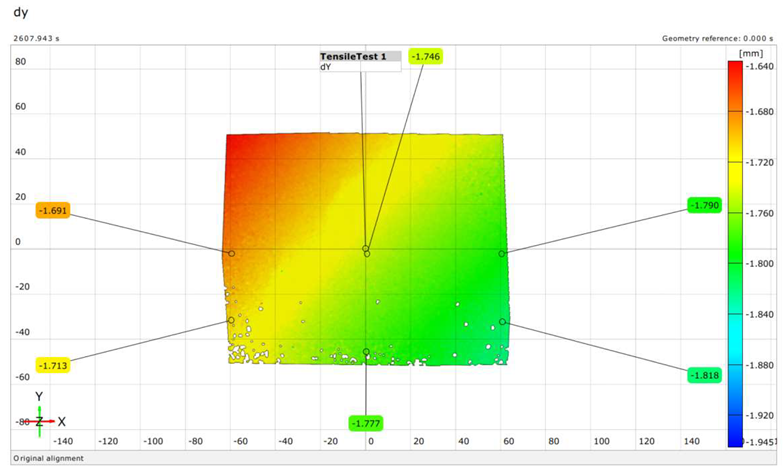 |
| S (Num.) | 136 |  |
| Rf (Exp.) | 93 |  |
| Rf (Num.) | 93 |  |
| Sf (Exp.) | 97 | 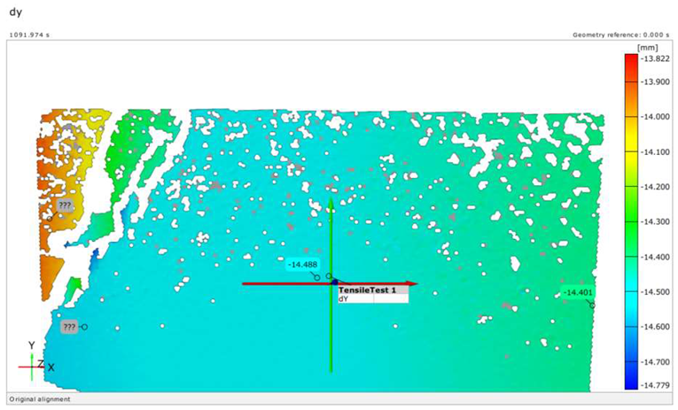 |
| Sf (Num.) | 97 |  |
| Rno (Exp.) | 95 | 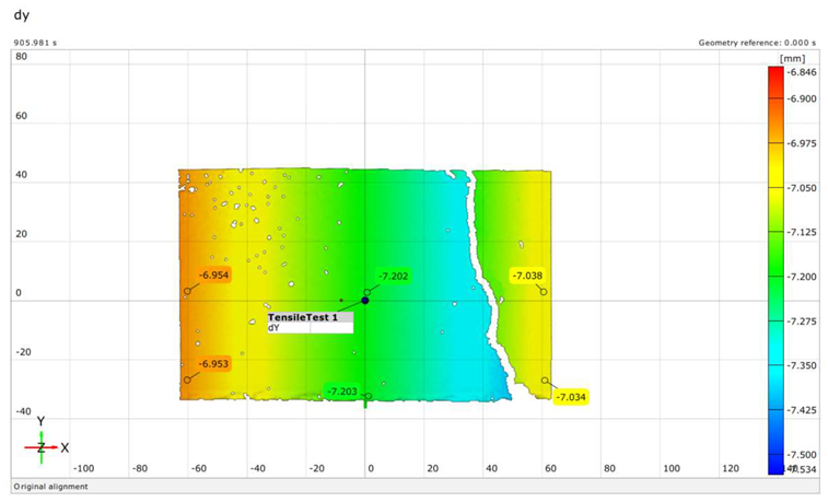 |
| Rno (Num.) | 95 |  |
| Case | Max. Load (Force) P [kN] | Max. Deflection ∆ [mm] | Section | Tension Damage Coefficient (dt) |
|---|---|---|---|---|
| R | 431.66 | 8.5 | - |  |
| A-A |  | |||
| C-C |  | |||
| D-D |  | |||
| S | 449.89 | 8 | - |  |
| A-A | 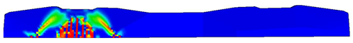 | |||
| C-C | 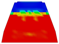 | |||
| D-D | 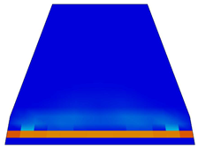 | |||
| Rf | 93.61 | 12.46 | - |  |
| A-A |  | |||
| B-B | 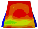 | |||
| C-C | 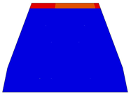 | |||
| Sf | 96.97 | 14.79 | - |  |
| A-A |  | |||
| B-B |  | |||
| C-C | 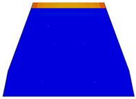 | |||
| Rno | 97.5 | 7.59 | - | 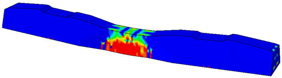 |
| A-A |  | |||
| B-B |  | |||
| C-C | 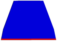 | |||
| Sno | 102.6 | 7.91 | - |  |
| A-A |  | |||
| B-B | 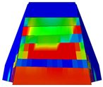 | |||
| C-C |  |
| Case | Section | Steel Stress Intensity (σ/σy) 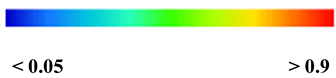 |
|---|---|---|
| R | - | 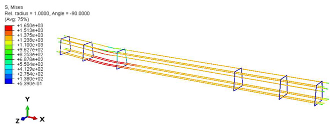 |
| A-A |  | |
| C-C |  | |
| S | - |  |
| A-A |  | |
| C-C |  | |
| Rf | - |  |
| A-A |  | |
| B-B |  | |
| Sf | - | 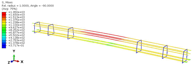 |
| A-A |  | |
| B-B | 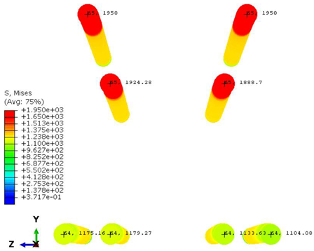 | |
| Rno | - | 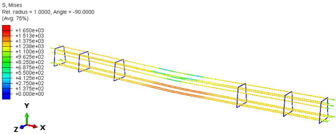 |
| A-A | 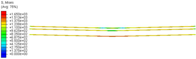 | |
| B-B | 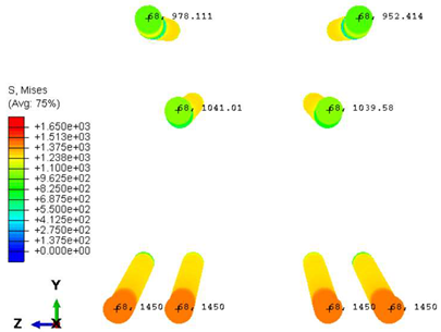 | |
| Sno | - |  |
| A-A |  | |
| B-B | 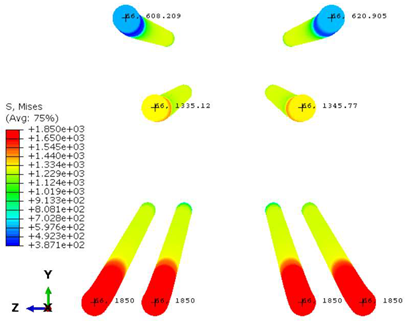 |
Disclaimer/Publisher’s Note: The statements, opinions and data contained in all publications are solely those of the individual author(s) and contributor(s) and not of MDPI and/or the editor(s). MDPI and/or the editor(s) disclaim responsibility for any injury to people or property resulting from any ideas, methods, instructions or products referred to in the content. |
© 2024 by the authors. Licensee MDPI, Basel, Switzerland. This article is an open access article distributed under the terms and conditions of the Creative Commons Attribution (CC BY) license (https://creativecommons.org/licenses/by/4.0/).
Share and Cite
Németh, A.; Ibrahim, S.K.; Movahedi Rad, M.; Szalai, S.; Major, Z.; Kocsis Szürke, S.; Jóvér, V.; Sysyn, M.; Kurhan, D.; Harrach, D.; et al. Laboratory and Numerical Investigation of Pre-Tensioned Reinforced Concrete Railway Sleepers Combined with Plastic Fiber Reinforcement. Polymers 2024, 16, 1498. https://doi.org/10.3390/polym16111498
Németh A, Ibrahim SK, Movahedi Rad M, Szalai S, Major Z, Kocsis Szürke S, Jóvér V, Sysyn M, Kurhan D, Harrach D, et al. Laboratory and Numerical Investigation of Pre-Tensioned Reinforced Concrete Railway Sleepers Combined with Plastic Fiber Reinforcement. Polymers. 2024; 16(11):1498. https://doi.org/10.3390/polym16111498
Chicago/Turabian StyleNémeth, Attila, Sarah Khaleel Ibrahim, Majid Movahedi Rad, Szabolcs Szalai, Zoltán Major, Szabolcs Kocsis Szürke, Vivien Jóvér, Mykola Sysyn, Dmytro Kurhan, Dániel Harrach, and et al. 2024. "Laboratory and Numerical Investigation of Pre-Tensioned Reinforced Concrete Railway Sleepers Combined with Plastic Fiber Reinforcement" Polymers 16, no. 11: 1498. https://doi.org/10.3390/polym16111498
APA StyleNémeth, A., Ibrahim, S. K., Movahedi Rad, M., Szalai, S., Major, Z., Kocsis Szürke, S., Jóvér, V., Sysyn, M., Kurhan, D., Harrach, D., Baranyai, G., Fekete, I., Nagy, R., Csótár, H., Madarász, K., Pollák, A., Molnár, B., Hermán, B., Kuczmann, M., ... Fischer, S. (2024). Laboratory and Numerical Investigation of Pre-Tensioned Reinforced Concrete Railway Sleepers Combined with Plastic Fiber Reinforcement. Polymers, 16(11), 1498. https://doi.org/10.3390/polym16111498