
Enhanced and Proficient Soft Template Array of Polyaniline—TiO2 Nanocomposites Fibers Prepared Using Anionic Surfactant for Fuel Cell Hydrogen Storage

 , , , , , ,
Abstract
:1. Introduction
2. Materials and Methods
2.1. Synthesis of Porous TiO2 Nanoparticles
2.2. Synthesis of Polyaniline Nanofibers
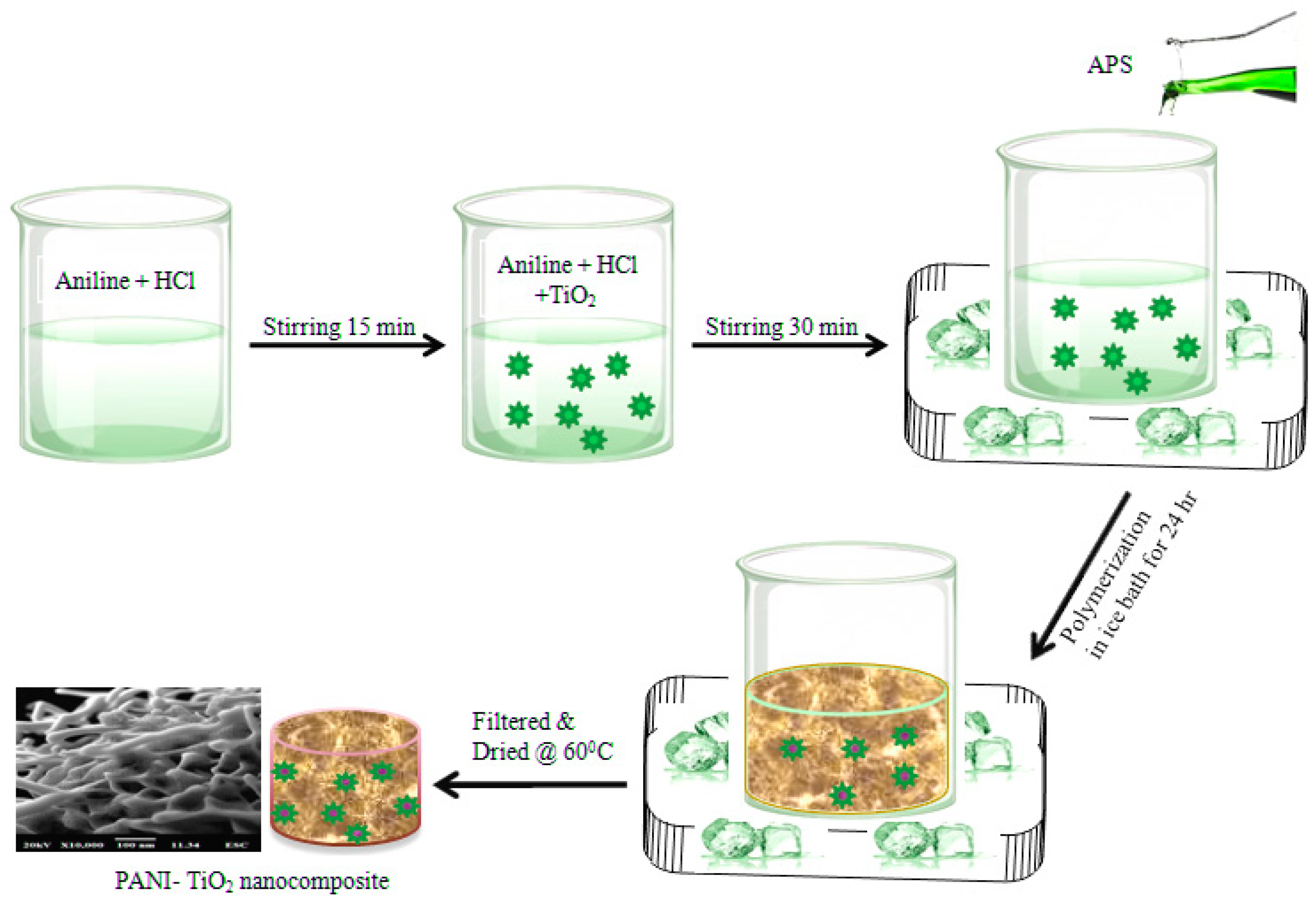
2.3. Synthesis of Polyaniline–TiO2 Nanocomposite Fibers
3. Characterization Techniques
4. Results and Discussion
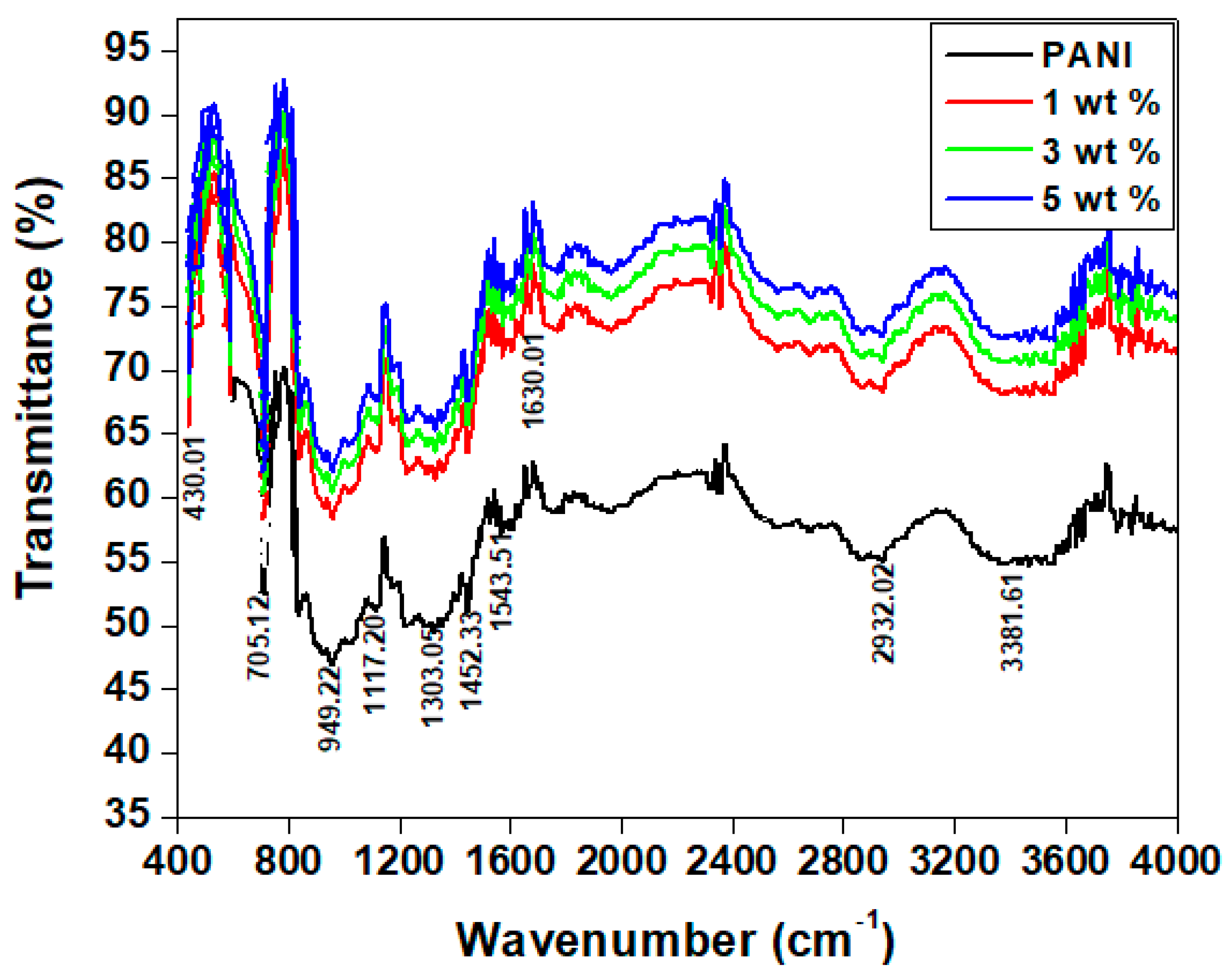
4.1. FTIR Spectra
4.2. XRD Pattern
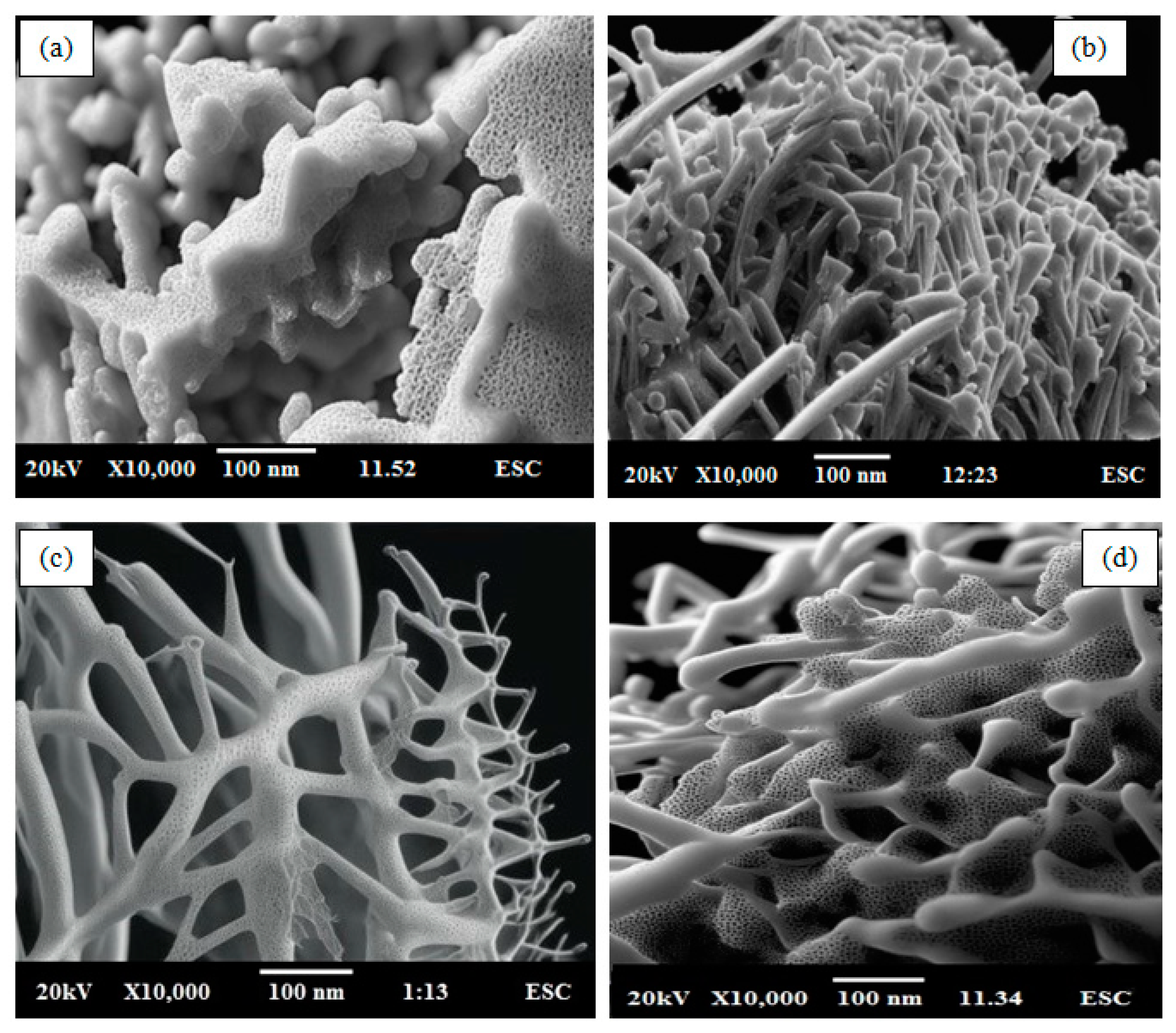
4.3. SEM Analysis
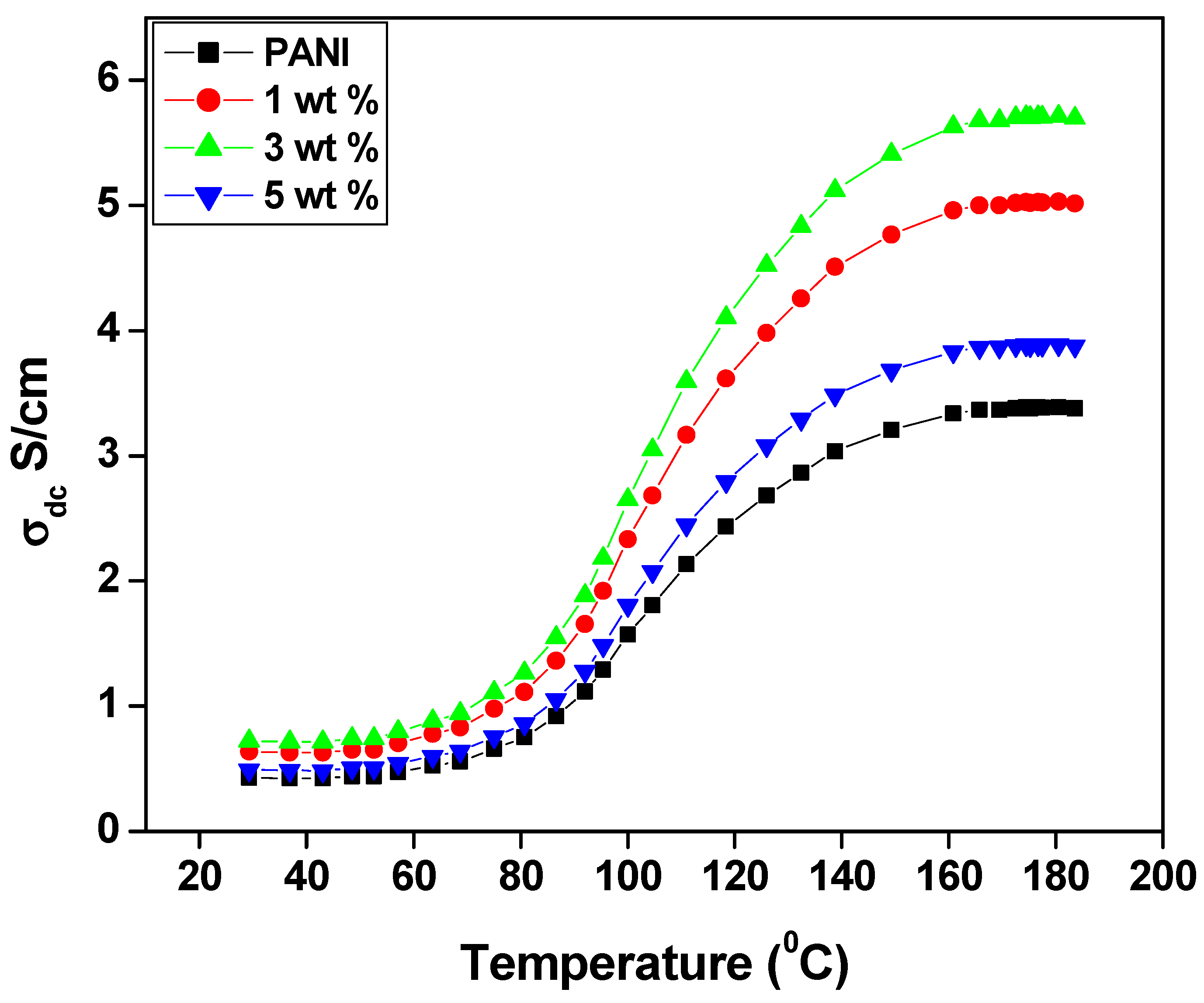
4.4. DC Conductivity
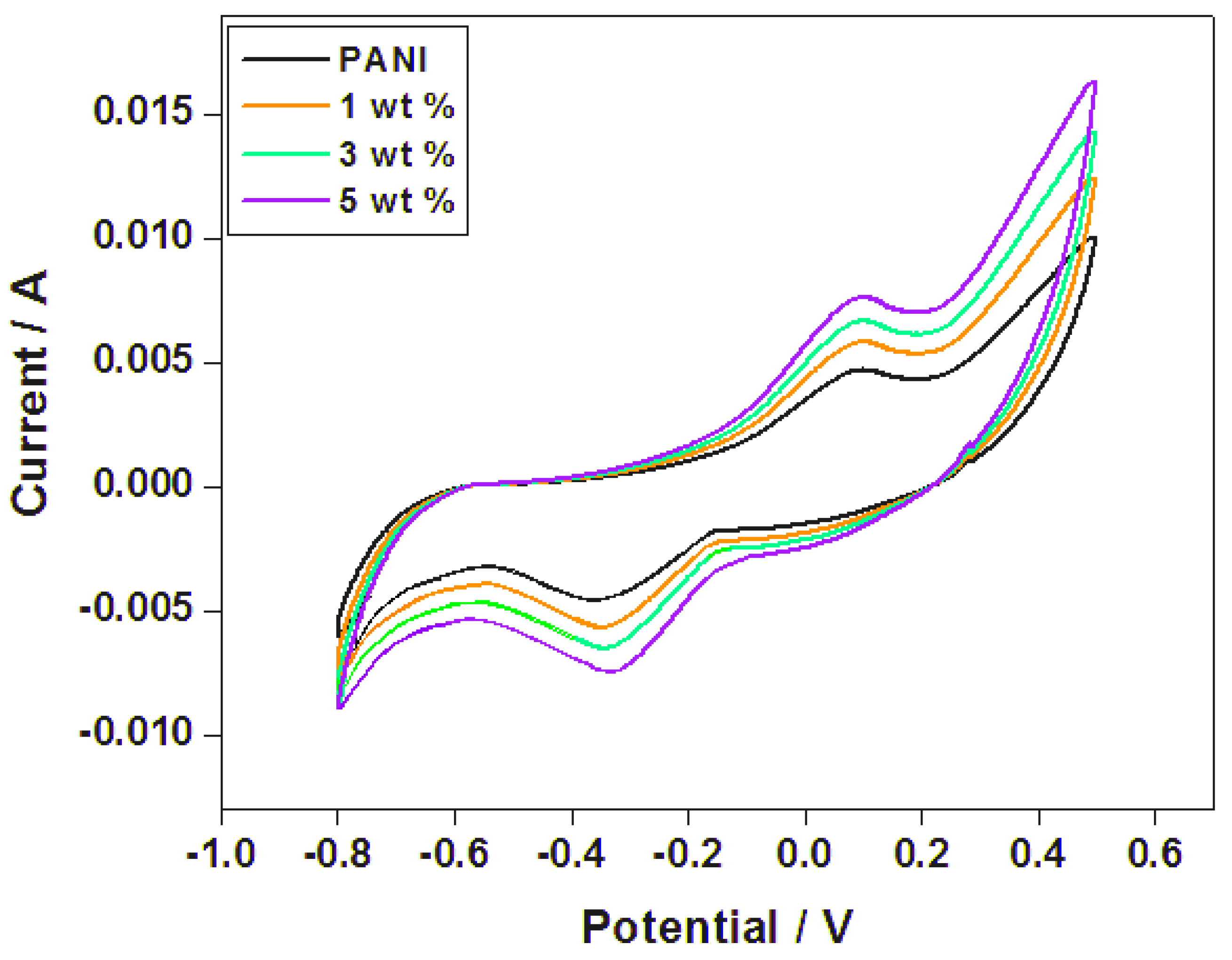
4.5. Cyclic Voltammetry
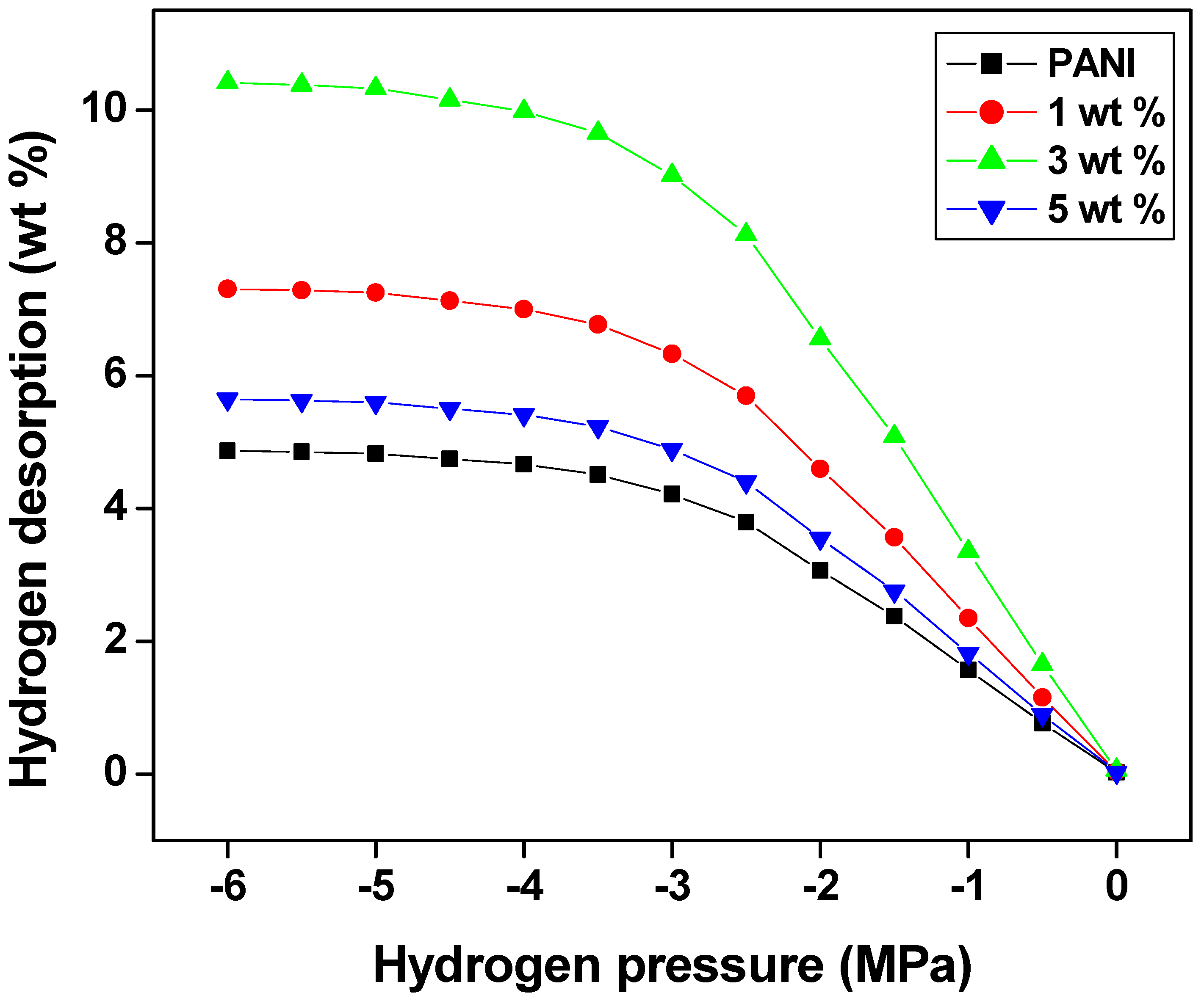
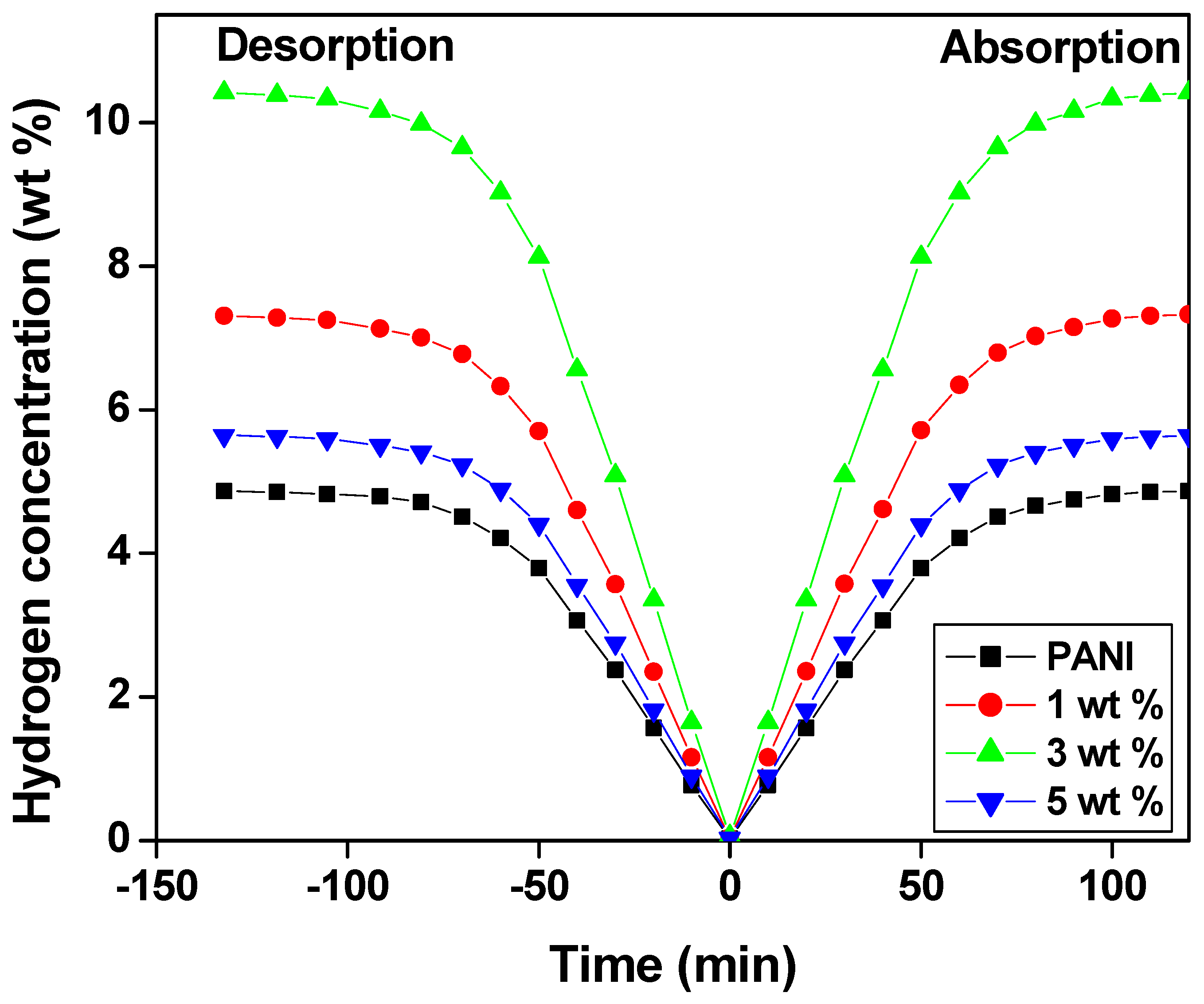
4.6. Hydrogen Sorption Measurement
5. Conclusions
Author Contributions
Funding
Institutional Review Board Statement
Data Availability Statement
Conflicts of Interest
References
- Chen, Y.; Zhu, H.; Liu, Y. Preparation of activated rectangular polyaniline-based carbon tubes and their application in hydrogen adsorption. Int. J. Hydrogen Energy 2011, 36, 11738–11745. [Google Scholar] [CrossRef]
- Mahato, N.; Jang, H.; Dhyani, A.; Cho, S. Recent Progress in Conducting Polymers for Hydrogen Storage and Fuel Cell Applications. Polymers 2020, 12, 2480. [Google Scholar] [CrossRef]
- Lenin, R.; Singh, A.; Bera, C. Effect of dopants and morphology on the electrical properties of polyaniline for various applications. J. Mater. Sci. Mater. Electron. 2021, 32, 24710–24725. [Google Scholar] [CrossRef]
- Kamarudin, S.; Asmal Rani, M.S.; Mohammad, M.; Mohammed, N.H.; Su’ait, M.S.; Ibrahim, M.A.; Asim, N.; Razali, H. Investigation on size and conductivity of polyaniline nanofiber synthesised by surfactant-free polymerization. J. Mater. Res. Technol. 2021, 14, 255–261. [Google Scholar] [CrossRef]
- Cho, S.J.; Choo, K.; Kim, D.P.; Kim, J.W. H2 sorption in HCl-treated polyaniline and polypyrrole. Catal. Today 2007, 120, 336–340. [Google Scholar] [CrossRef]
- Ensafi, A.A.; Jafari-Asl, M.; Nabiyan, A.; Rezaei, B.; Dinari, M. Hydrogen storage in hybrid of layered double hydroxides/reduced graphene oxide using spillover mechanism. Energy 2016, 99, 103–114. [Google Scholar] [CrossRef]
- Padmapriya, S.; Harinipriya, S.; Jaidev, K.; Sudha, V.; Kumar, D.; Pal, S. Storage and evolution of hydrogen in acidic medium by polyaniline. Int. J. Energy Res. 2018, 42, 1196–1209. [Google Scholar] [CrossRef]
- Singh, R.R.; Subodh, S.; Sharma, P.K.; Vinay, S.; Ram, G.; Nihal, S.; Sharma, S.S.; Vijay, Y.K. Synthesis of Graphene Oxide/Polyaniline Composites for Hydrogen Storage. Adv. Sci. Eng. Med. 2017, 9, 391–397. [Google Scholar]
- Ke, G.; Chowdhury, M.H.; Jin, X.; Li, W. Fabrication and properties of polyaniline/ramie composite fabric based on in situ polymerization. Polym. Polym. Compos. 2021, 29, S914–S925. [Google Scholar] [CrossRef]
- Ka, N.; Kapse, S.; Manoj, M.; Thapa, R.; Rout, C.S. 2D-black phosphorus/polyaniline hybrids for efficient supercapacitor and hydrogen evolution reaction applications. Sustain. Energy Fuels 2022, 6, 4285–4298. [Google Scholar]
- Li, M.M.; Wang, C.C.; Zhou, Y.T.; Yang, C.C. Clarifying the polyaniline effect on superior electrochemical performances of hydrogen storage alloys. Electrochim. Acta 2021, 365, 137336. [Google Scholar] [CrossRef]
- Neto, G.R.d.A.; Matheus, F.H.; Beatrice, C.A.G.; Leiva, D.R.; Pessan, L.A. Fundamentals and recent advances in polymer composites with hydride-forming metals for hydrogen storage applications. Int. J. Hydrogen Energy 2022, 47, 34139–34164. [Google Scholar] [CrossRef]
- Liu, C.; Fan, Y.Y.; Liu, M.; Cong, H.T.; Cheng, H.M.; Dresselhaus, M.S. Hydrogen Storage in Single-Walled Carbon Nanotubes at Room Temperature. Science 1999, 286, 1127–1129. [Google Scholar] [CrossRef]
- Attia, N.F.; Zakria, A.M.; Nour, M.A.; Abd El-Ghany, N.A.; Elashery, S.E.A. Rational strategy for construction of multifunctional coatings for achieving high fire safety, antibacterial, UV protection and electrical conductivity functions of textile fabrics. Mater. Today Sustain. 2023, 23, 100450. [Google Scholar] [CrossRef]
- Illing, G.; Hellgardt, K.; Wakeman, R.J.; Jungbauer, A. Preparation and characterization of polyaniline based membranes for gas separation. J. Membr. Sci. 2001, 184, 69–78. [Google Scholar] [CrossRef]
- Germain, J.; Svec, F.; Frèchet, J.M.J. Nanoporous polymers for hydrogen storage. Small 2009, 5, 1098–1111. [Google Scholar] [CrossRef] [PubMed]
- Anderson, M.R.; Mattes, B.R.; Reiss, H.; Kaner, R.B. Conjugated Polymer Films for Gas Separations. Science 1991, 252, 1412–1415. [Google Scholar] [CrossRef]
- Gulsen, D.; Hacarloglu, P.; Toppare, L.; Yilmaz, L. Effect of preparation parameters on the performance of conductive composite gas separation membranes. J. Membr. Sci. 2001, 182, 29–39. [Google Scholar] [CrossRef]
- Germain, J.; Frèchet, J.M.J.; Svec, F. Nanoporous, hypercrosslinked polypyrroles: Effect of crosslinking moiety on pore size and selective gas adsorption. Chem. Commun. 2009, 12, 1526–1528. [Google Scholar] [CrossRef] [PubMed]
- Al-Aoh, H.A.; Badi, N.; Roy, A.S.; Alsharari, A.M.; Abd El Wanees, S.; Albaqami, A.; Ignatiev, A. Preparation of Anionic Surfactant-Based One-Dimensional Nanostructured Polyaniline Fibers for Hydrogen Storage Applications. Polymers 2023, 15, 1658. [Google Scholar] [CrossRef]
- Qi, Y.-N.; Chu, H.-L.; Xu, F.; Sun, L.-X.; Zhang, Y.; Zhang, J.; Qiu, S.-J.; Yuan, H. Effect of polyaniline on hydrogen absorption–desorption properties and discharge capacity of AB3 alloy. Int. J. Hydrogen Energy 2007, 32, 3395–3401. [Google Scholar] [CrossRef]
- Attia, N.F.; Geckeler, K.E. Polyaniline–Polypyrrole Composites with Enhanced Hydrogen Storage Capacities. Macromol. Rapid Commun. 2013, 34, 931–937. [Google Scholar] [CrossRef] [PubMed]
- Virji, S.; Kaner, R.B.; Weiller, B.H. Hydrogen sensors based on conductivity changes in polyaniline nanofibers. J. Phys. Chem. B 2006, 110, 22266–22270. [Google Scholar] [CrossRef] [PubMed]
- Roy, A.S. Antistatic and Dielectric properties of one-dimensional Al2+:Nd2O3 nanowire doped polyaniline nanocomposites for electronic application. Sens. Actuators A Phys. 2018, 280, 1–7. [Google Scholar] [CrossRef]
- Sampreeth, T.; Al-Maghrabi, M.A.; Bahuleyan, B.K.; Ramesan, M.T. Synthesis, characterization, thermal properties, conductivity and sensor application study of polyaniline/cerium-doped titanium dioxide nanocomposites. J. Mater. Sci. 2018, 53, 591–603. [Google Scholar] [CrossRef]
- Ham, J.; Park, S.; Jeon, N. Conductive Polyaniline–Indium Oxide Composite Films Prepared by Sequential Infiltration Synthesis for Electrochemical Energy Storage. ACS Omega 2023, 8, 946–953. [Google Scholar] [CrossRef]
- Namsheer, K.; Rout, C.S. Conducting polymers: A comprehensive review on recent advances in synthesis, properties and applications. RSC Adv. 2021, 11, 5659–5697. [Google Scholar]
- Rahman, K.H.; Kar, A.K. Structural and optical properties of ex-situ polymerized PAni-TiO2 nanocomposite. Mater. Today Proc. 2019, 18, 1067–1071. [Google Scholar] [CrossRef]
- Bitao, S.; Shixiong, M.; Shixiong, S.; Yongchun, T. Synthesis and characterization of conductive polyaniline/TiO2 composite nanofibers. Front. Chem. China 2007, 2, 123–126. [Google Scholar]
- Krukiewicz, K.; Katunin, A. The effect of reaction medium on the conductivity and morphology of polyaniline doped with camphorsulfonic acid. Synth. Met. 2016, 214, 45–49. [Google Scholar] [CrossRef]
- White, T.; Li, Y.; Lim, S.H. Structure control and its influence on photoactivity and phase transformation of TiO2 nano-particles. Rev. Adv. Mater. Sci. 2003, 5, 211–215. [Google Scholar]
- Balikile, R.D.; Roy, A.S.; Nagaraju, S.C.; Ramgopal, G. Conductivity properties of hollow ZnFe2O4 Nanofibers doped Polyaniline Nanocomposites. J. Mater. Sci. Mater. Electron. 2017, 28, 7368–7375. [Google Scholar] [CrossRef]
- Varnaitė-Žuravliova, S.; Savest, N.; Abraitienė, A.; Baltušnikaitė-Guzaitienė, J.; Krumme, A. Investigation of influence of conductivity on the polyaniline fiber mats, produced via electrospinning. Mater. Res. Express 2018, 5, 055308. [Google Scholar] [CrossRef]
- Deshmukh, S.P.; Dhodamani, A.g.; Patil, S.M.; Mullani, S.B.; More, K.V.; Delekar, S.D. Interfacially Interactive Ternary Silver-Supported Polyaniline/Multiwalled Carbon Nanotube Nanocomposites for Catalytic and Antibacterial Activity. ACS Omega 2020, 5, 219–227. [Google Scholar] [CrossRef] [PubMed]
- Ayad, M.M.; Amer, W.A.; Kotp, M.G.; Minisy, I.M.; Rehab, A.F.; Kopecký, D.; Fitl, P. Synthesis of silver-anchored polyaniline–chitosan magnetic nanocomposite: A smart system for catalysis. RSC Adv. 2017, 7, 18553–18560. [Google Scholar] [CrossRef]
- Minisy, I.M.; Salahuddin, N.A.; Ayad, M.M. In vitro release study of ketoprofen-loaded chitosan/polyaniline nanofibers. Polym. Bull. 2021, 78, 5609–5622. [Google Scholar] [CrossRef]
- Chougala, L.S.; Yatnatti, M.S.; Linganagoudar, R.K.; Kamble, R.R.; Kadadevarmath, J.S. A Simple Approach on Synthesis of TiO2 Nanoparticles and its Application in dye Sensitized Solar Cells. J. Nano-Electron. Phys. 2017, 9, 04005. [Google Scholar] [CrossRef]
- Abisharani, J.M.; DineshKumar, R.; Devikala, S.; Arthanareeswari, M.; Ganesan, S. Influence of 2,4-Diamino-6-Phenyl-1-3-5-triazine on bio synthesized TiO2 dye-sensitized solar cell fabricated using poly(ethylene glycol) polymer electrolyte. Mater. Res. Express 2020, 7, 025507. [Google Scholar] [CrossRef]
- Wahi, R.K.; Liu, Y.; Falkner, J.C.; Colvin, V.L. Solvothermal synthesis and characterization of anatase TiO2 nanocrystals with ultrahigh surface area. J. Colloid Interface Sci. 2006, 302, 530–536. [Google Scholar] [CrossRef]
- Perdigão, P.; Morais Faustino, B.M.; Faria, J.; Canejo, J.P.; Borges, J.P.; Ferreira, I.; Baptista, A.C. Conductive Electrospun Polyaniline/Polyvinylpyrrolidone Nanofibers: Electrical and Morphological Characterization of New Yarns for Electronic Textiles. Fibers 2020, 8, 24. [Google Scholar] [CrossRef]
- Roy, A.; Parveen, A.; Deshpande, R.; Bhat, R.; Koppalkar, A. Microscopic and Dielectric studies of ZnO nanoparticles loaded in ortho-chloropolyaniline nanocomposites. J. Nanopart. Res. 2013, 15, 1337. [Google Scholar] [CrossRef]
- Bednarczyk, K.; Matysiak, W.; Tański, T.; Janeczek, H.; Schab-Balcerzak, E.; Libera, M. Effect of polyaniline content and protonating dopants on electroconductive composites. Sci. Rep. 2021, 11, 7487. [Google Scholar] [CrossRef]
- Mohammadi, B.; Pirsa, S.; Alizadeh, M. Preparing chitosan–polyaniline nanocomposite film and examining its mechanical, electrical, and antimicrobial properties. Polym. Polym. Compos. 2019, 27, 507–517. [Google Scholar] [CrossRef]
- Rahy, A.; Yang, D.J. Synthesis of highly conductive polyaniline nanofibers. Mater. Lett. 2008, 62, 4311–4314. [Google Scholar] [CrossRef]
- Wang, N.; Li, J.; Lv, W.; Feng, J.; Yan, W. Synthesis of polyaniline/TiO2 composite with excellent adsorption performance on acid red G. RSC Adv. 2015, 5, 21132. [Google Scholar] [CrossRef]
- Sambaza, S.S.; Maity, A.; Pillay, K. Polyaniline-Coated TiO2 Nanorods for Photocatalytic Degradation of Bisphenol A in Water. ACS Omega 2020, 5, 29642–29656. [Google Scholar] [CrossRef]
- Shklovskii, B.I.; Efros, A.L. Variable-Range Hopping Conduction. In Electronic Properties of Doped Semiconductors; Springer Series in Solid-State Sciences; Springer: Berlin/Heidelberg, Germany, 1984; Volume 45. [Google Scholar]
- Sarkar, A.; Ghosh, P.; Meikap, A.K.; Chattopadhyay, S.K.; Chatterjee, S.K.; Chowdhury, P.; Roy, K.; Saha, B. Electrical-transport properties of iodine-doped conducting polyaniline. J. Appl. Polym. Sci. 2008, 108, 2312–2320. [Google Scholar] [CrossRef]
- Vellakkat, M.; Kamath, A.; Raghu, S.; Chapi, S.; Hundekal, D. Dielectric Constant and Transport Mechanism of Percolated Polyaniline Nanoclay Composites. Ind. Eng. Chem. Res. 2014, 53, 16873–16882. [Google Scholar] [CrossRef]
- Badi, N.; Mekala, R.; Khasim, S.; Roy, A.S.; Ignatiev, A. Enhanced dielectric performance in PVDF/Al-Al2O3 core-shell nanocomposites. J. Mater. Sci. Mater. Electron. 2018, 29, 10593–10599. [Google Scholar] [CrossRef]
- Bandgar, D.K.; Navale, S.T.; Vanalkar, S.A.; Kim, J.H.; Harale, N.S.; Patil, P.S.; Patil, V.B. Synthesis, structural, morphological, compositional and electrical transport properties of polyaniline/α-Fe2O3 hybrid nanocomposites. Synth. Met. 2014, 195, 350–358. [Google Scholar] [CrossRef]
- Najim, T.S.; Salim, A.J. Polyaniline nanofibers and nanocomposites: Preparation, characterization, and application for Cr(VI) and phosphate ions removal from aqueous solution. Arab. J. Chem. 2017, 10, S3459–S3467. [Google Scholar] [CrossRef]
- Komaba, K.; Goto, H. Synthesis of Polyaniline and Polyaniline/Fiber Composites in Geothermal Water. J. Water Chem. Technol. 2023, 45, 52–62. [Google Scholar] [CrossRef]
- Freitas, T.V.; Sousa, E.A.; Fuzari, G.C., Jr.; Arlindo, E.P. Different morphologies of polyaniline nanostructures synthesized by interfacial polymerization. Mater. Lett. 2018, 224, 42–45. [Google Scholar] [CrossRef]
- Liu, W.; Chang, Y.-C.; Zhang, J.; Liu, H. Wet-Spun Side-by-Side Electrically Conductive Composite Fibers. ACS Appl. Electron. Mater. 2022, 4, 1979–1988. [Google Scholar] [CrossRef]
- Bhadra, J.; Al-Thani, N.; Madi, N.; Al-Maadeed, M. Effects of aniline concentrations on the electrical and mechanical properties of polyaniline polyvinyl alcohol blends. Arab. J. Chem. 2017, 10, 664–672. [Google Scholar] [CrossRef]
- Fang, B.; Yan, J.; Chang, D.; Piao, J.; Ma, K.M.; Gu, Q.; Gao, P.; Chai, Y.; Tao, X. Scalable production of ultrafine polyaniline fibres for tactile organic electrochemical transistors. Nat. Commun. 2022, 13, 2101. [Google Scholar] [CrossRef]
- Santim, R.H.; Sanches, A.O.; da Silva, M.J.; McMahan, C.M.; Malmonge, J.A. Electrically conductive nanocomposites produced by in situ polymerization of pyrrole in pre-vulcanized natural rubber latex. Polym. Compos. 2022, 43, 2972–2979. [Google Scholar] [CrossRef]
- Moussa, M.A.; Abdel Rehim, M.H.; Ghoneim, A.M.; Khairy, S.A.; Soliman, M.A.; Turky, G.M. Dielectric investigations and charge transport in PS-PAni composites with ionic and nonionic surfactants. J. Phys. Chem. Solids 2019, 133, 163–170. [Google Scholar] [CrossRef]
- Sharifian, M.; Kern, W.; Riess, G. A Bird’s-Eye View on Polymer-Based Hydrogen Carriers for Mobile Applications. Polymers 2022, 14, 4512. [Google Scholar] [CrossRef]
- Galal, A.; Zaki, M.M.; Atta, N.F.; Samaha, S.; Nasr, H.; Attia, N.F. Electroremoval of copper ions from aqueous solutions using chemically synthesized polypyrrole on polyester fabrics. J. Water Process Eng. 2021, 43, 102287. [Google Scholar] [CrossRef]
- Sule, R.; Mishra, A.K.; Nkambule, T.T. Recent advancement in consolidation of MOFs as absorbents for hydrogen storage. Int. J. Energy Res. 2021, 45, 12481–12499. [Google Scholar] [CrossRef]
- Mehranfar, A.; Izadyar, M.; Esmaeili, A.A. Hydrogen storage by N-ethylcarbazol as a new liquid organic hydrogen carrier: A DFT study on the mechanism. Int. J. Hydrogen Energy 2015, 40, 5797–5806. [Google Scholar] [CrossRef]
- Zhuo, Y.; Jung, S.; Shen, Y. Numerical Study of Hydrogen Desorption in an Innovative Metal Hydride Hydrogen Storage Tank. Energy Fuels 2021, 35, 10908–10917. [Google Scholar] [CrossRef]


Disclaimer/Publisher’s Note: The statements, opinions and data contained in all publications are solely those of the individual author(s) and contributor(s) and not of MDPI and/or the editor(s). MDPI and/or the editor(s) disclaim responsibility for any injury to people or property resulting from any ideas, methods, instructions or products referred to in the content. |
© 2023 by the authors. Licensee MDPI, Basel, Switzerland. This article is an open access article distributed under the terms and conditions of the Creative Commons Attribution (CC BY) license (https://creativecommons.org/licenses/by/4.0/).
Share and Cite
Badi, N.; Roy, A.S.; Al-Aoh, H.A.; Motawea, M.S.; Alghamdi, S.A.; M. Alsharari, A.; Albaqami, A.S.; Ignatiev, A. Enhanced and Proficient Soft Template Array of Polyaniline—TiO2 Nanocomposites Fibers Prepared Using Anionic Surfactant for Fuel Cell Hydrogen Storage. Polymers 2023, 15, 4186. https://doi.org/10.3390/polym15204186
Badi N, Roy AS, Al-Aoh HA, Motawea MS, Alghamdi SA, M. Alsharari A, Albaqami AS, Ignatiev A. Enhanced and Proficient Soft Template Array of Polyaniline—TiO2 Nanocomposites Fibers Prepared Using Anionic Surfactant for Fuel Cell Hydrogen Storage. Polymers. 2023; 15(20):4186. https://doi.org/10.3390/polym15204186
Chicago/Turabian StyleBadi, Nacer, Aashis S. Roy, Hatem A. Al-Aoh, Mohamed S. Motawea, Saleh A. Alghamdi, Abdulrhman M. Alsharari, Abdulrahman S. Albaqami, and Alex Ignatiev. 2023. "Enhanced and Proficient Soft Template Array of Polyaniline—TiO2 Nanocomposites Fibers Prepared Using Anionic Surfactant for Fuel Cell Hydrogen Storage" Polymers 15, no. 20: 4186. https://doi.org/10.3390/polym15204186
APA StyleBadi, N., Roy, A. S., Al-Aoh, H. A., Motawea, M. S., Alghamdi, S. A., M. Alsharari, A., Albaqami, A. S., & Ignatiev, A. (2023). Enhanced and Proficient Soft Template Array of Polyaniline—TiO2 Nanocomposites Fibers Prepared Using Anionic Surfactant for Fuel Cell Hydrogen Storage. Polymers, 15(20), 4186. https://doi.org/10.3390/polym15204186