Graphene Nanoplatelets as a Replacement for Carbon Black in Rubber Compounds


Abstract
:
1. Introduction
2. Experimental
2.1. Materials
2.2. Characterization of the FLAKES and the Compounds
3. Results
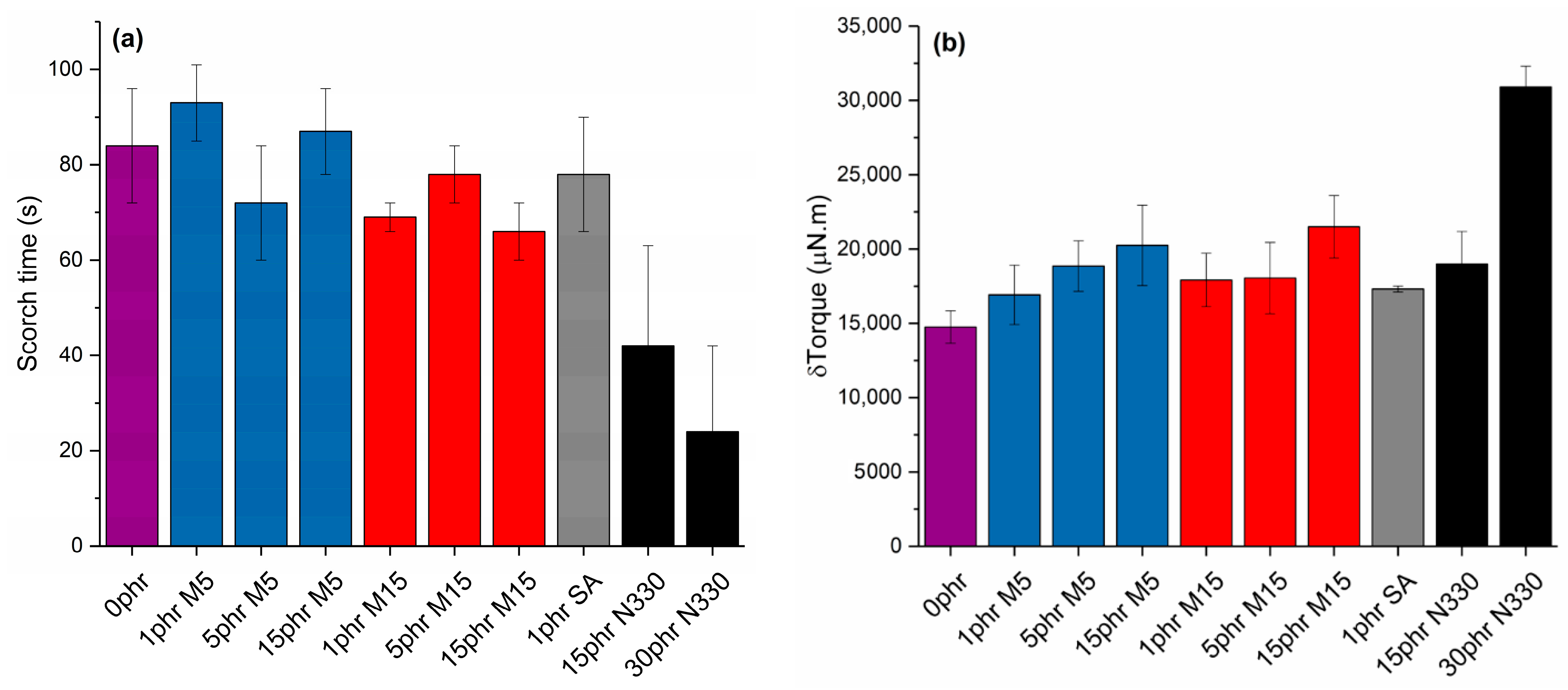
3.1. Processing Characteristics
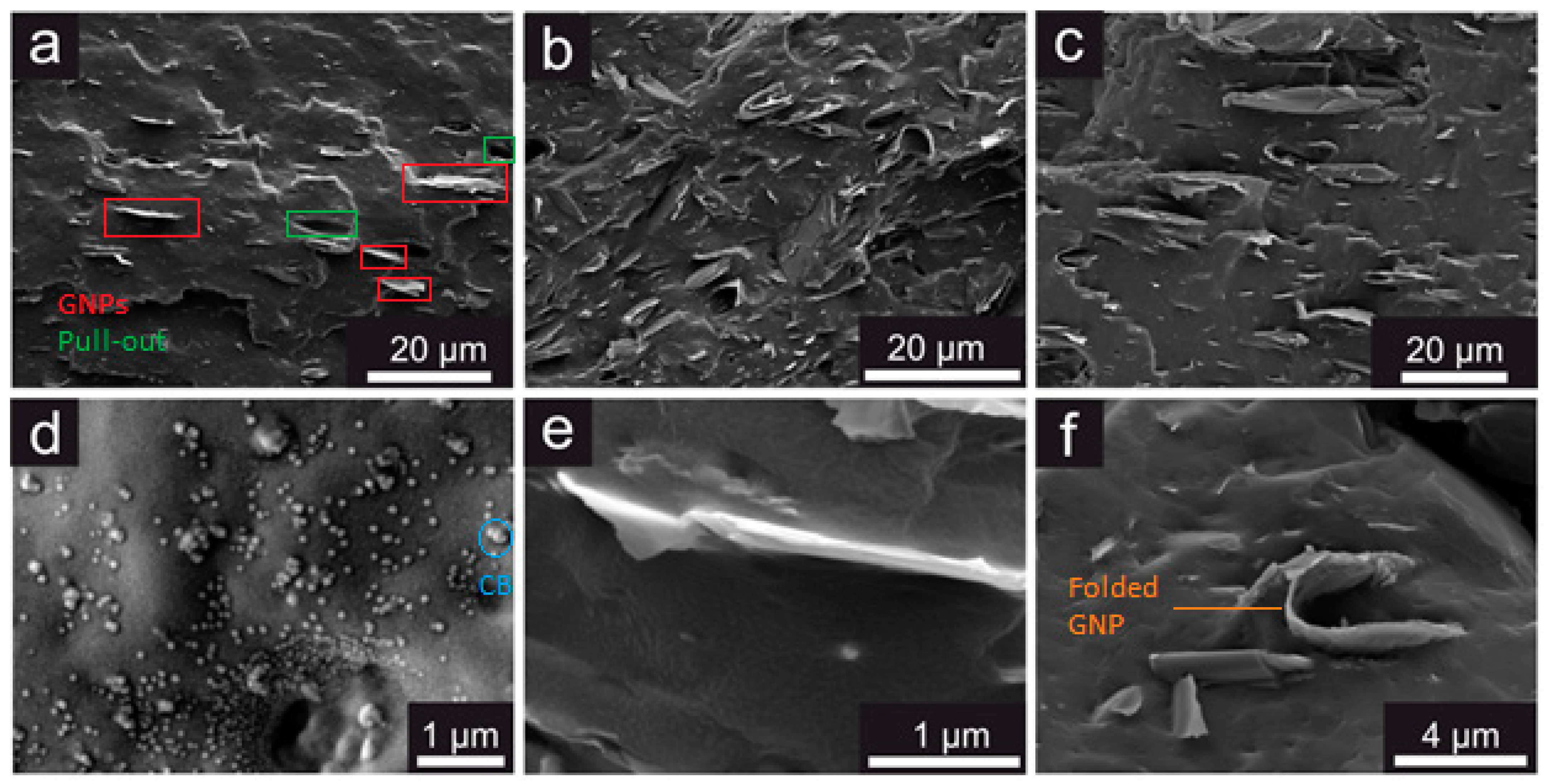
3.2. Microstructure of the NBR Nanocomposites
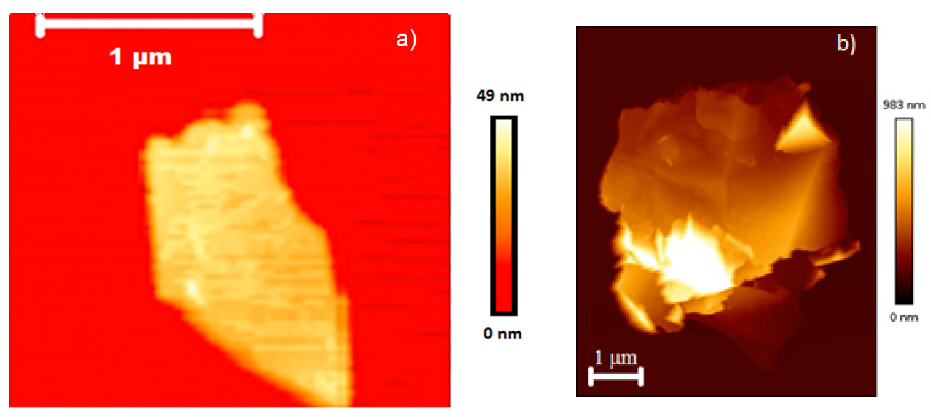
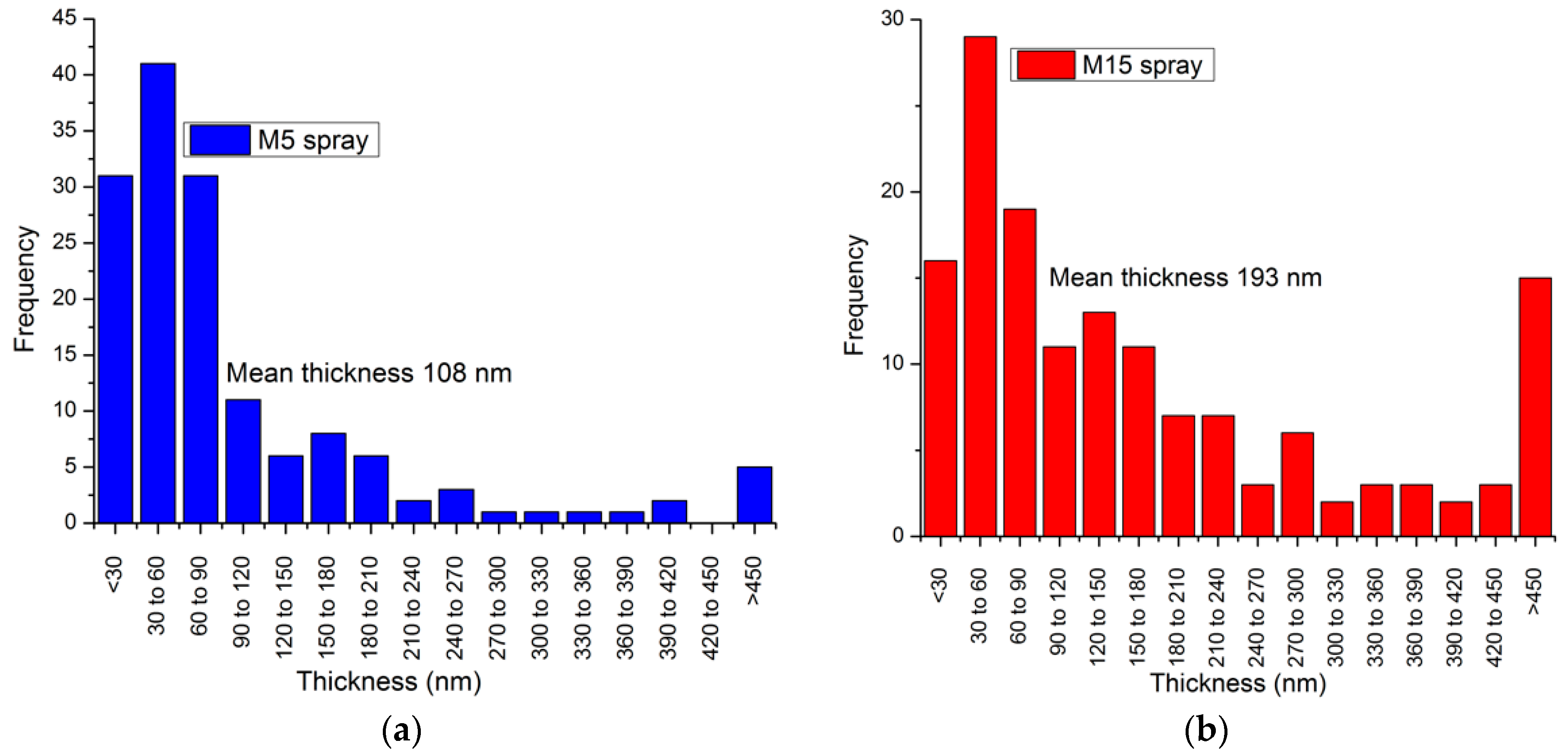
3.3. Characterisation of the Nanoplatelets
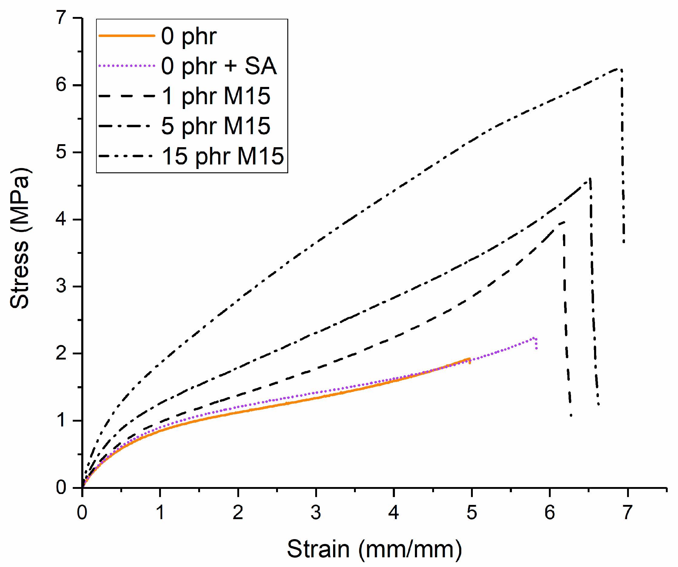
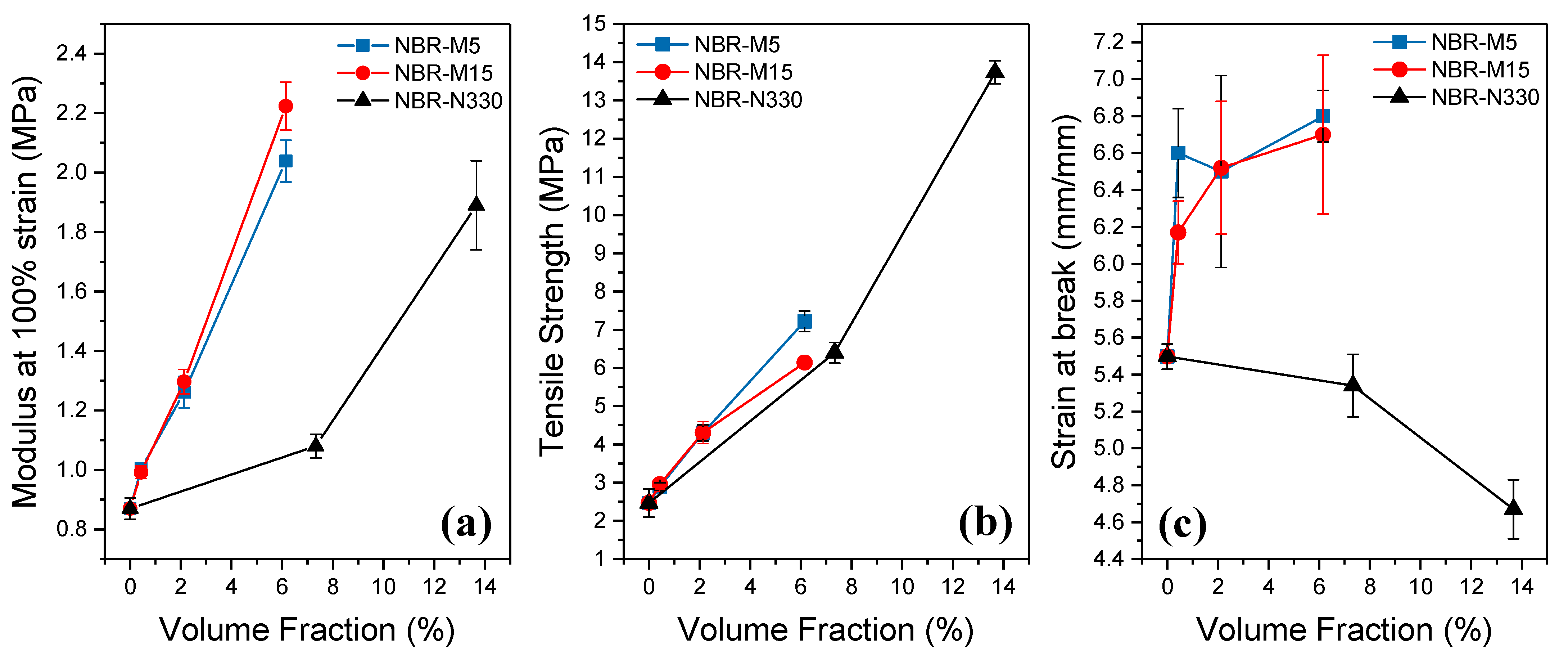
3.4. Mechanical Properties
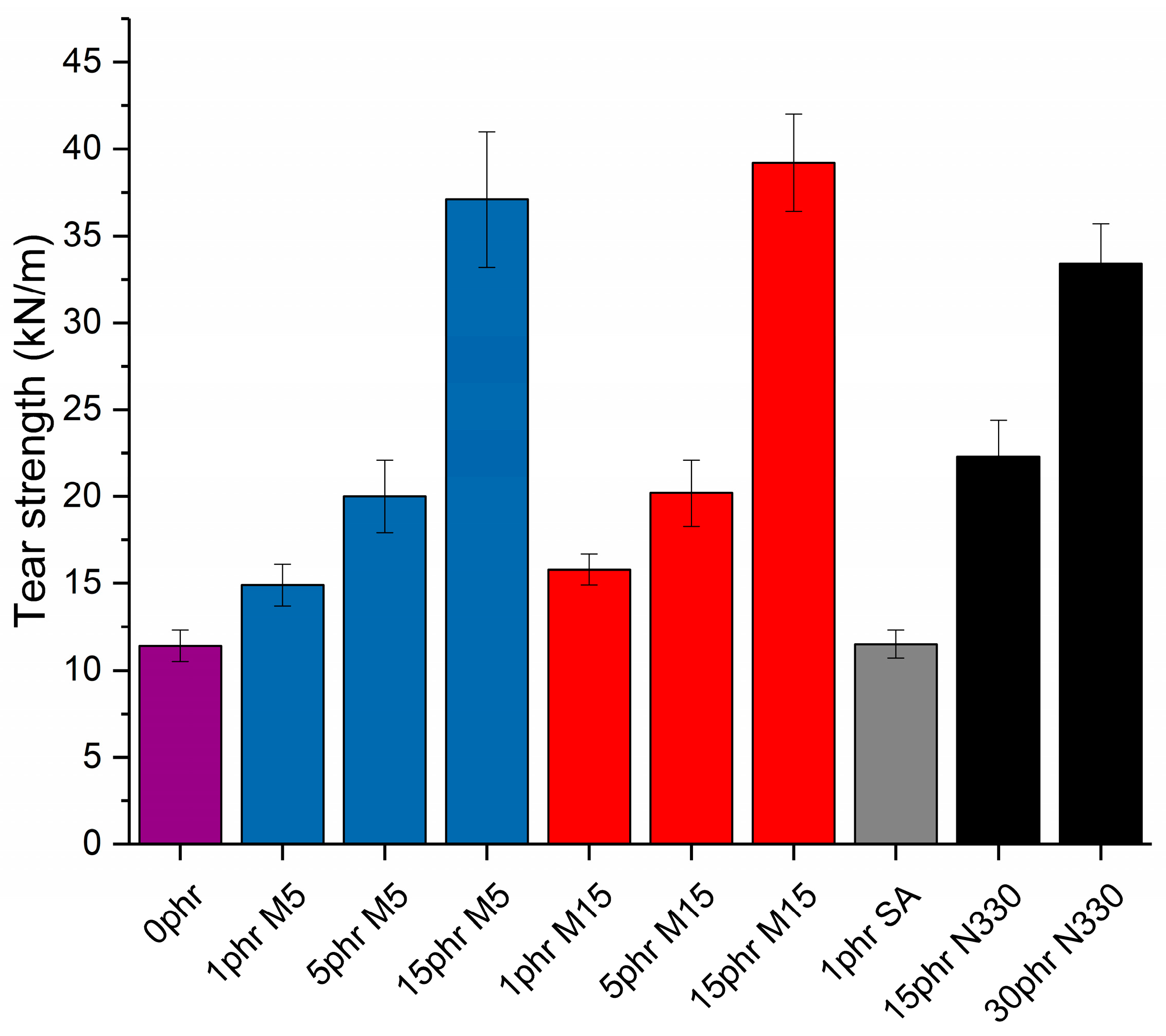
3.5. Tear Properties
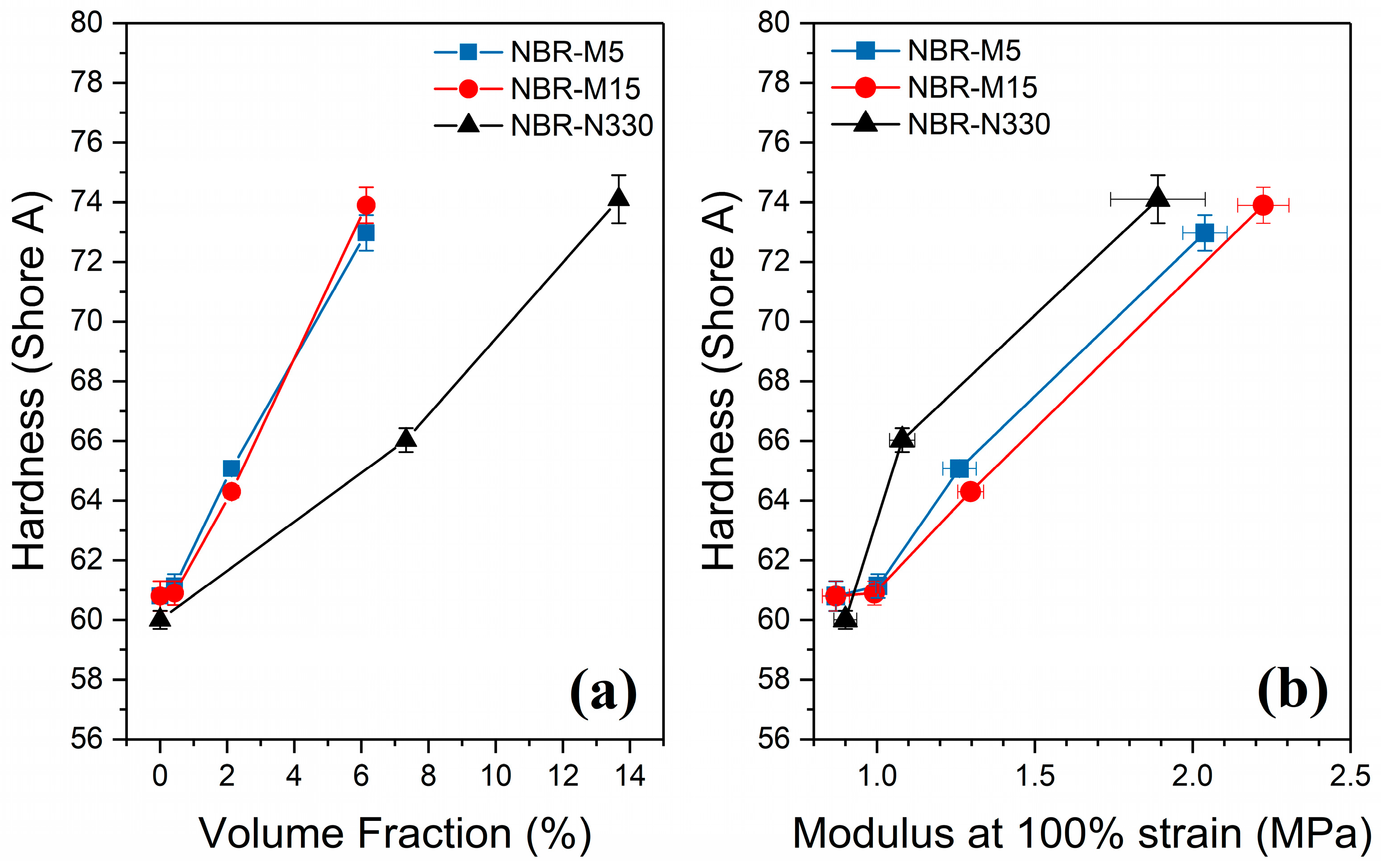
3.6. Hardness
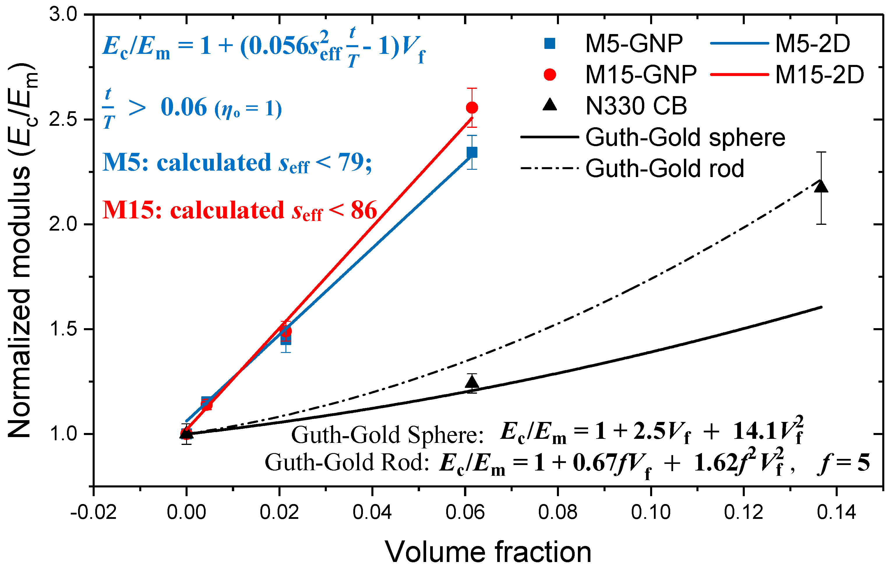
4. Discussion
Composite Micromechanics
5. Conclusions
Supplementary Materials
Author Contributions
Funding
Institutional Review Board Statement
Informed Consent Statement
Data Availability Statement
Acknowledgments
Conflicts of Interest
References
- Leblanc, J.L. Rubber–filler interactions and rheological properties in filled compounds. Prog. Polym. Sci. 2002, 27, 627–687. [Google Scholar] [CrossRef]
- Pawlyta, M.; Rouzaud, J.-N.; Duber, S. Raman microspectroscopy characterization of carbon blacks: Spectral analysis and structural information. Carbon 2015, 84, 479–490. [Google Scholar] [CrossRef]
- Iijima, S.; Ichihashi, T. Single-shell carbon nanotubes of 1-nm diameter. Nature 1993, 363, 603–605. [Google Scholar] [CrossRef]
- Novoselov, K.S.; Geim, A.K.; Morozov, S.V.; Jiang, D.; Zhang, Y.; Dubonos, S.V.; Grigorieva, I.V.; Firsov, A.A. Electric field effect in atomically thin carbon films. Science 2004, 306, 666–669. [Google Scholar] [CrossRef] [PubMed] [Green Version]
- Papageorgiou, D.G.; Kinloch, I.A.; Young, R.J. Mechanical properties of graphene and graphene-based nanocomposites. Prog. Mater. Sci. 2017, 90, 75–127. [Google Scholar] [CrossRef]
- Papageorgiou, D.G.; Li, Z.; Liu, M.; Kinloch, I.A.; Young, R.J. Mechanisms of mechanical reinforcement by graphene and carbon nanotubes in polymer nanocomposites. Nanoscale 2020, 12, 2228–2267. [Google Scholar] [CrossRef] [PubMed] [Green Version]
- Marsden, A.J.; Papageorgiou, D.G.; Vallés, C.; Liscio, A.; Palermo, V.; Bissett, M.A.; Young, R.J.; Kinloch, I.A. Electrical percolation in graphene–polymer composites. 2D Mater. 2018, 5, 032003. [Google Scholar] [CrossRef] [Green Version]
- Balandin, A.A.; Ghosh, S.; Bao, W.; Calizo, I.; Teweldebrhan, D.; Miao, F.; Lau, C.N. Superior Thermal Conductivity of Single-Layer Graphene. Nano Lett. 2008, 8, 902–907. [Google Scholar] [CrossRef] [PubMed]
- Zhu, Y.; Murali, S.; Cai, W.; Li, X.; Suk, J.W.; Potts, J.R.; Ruoff, R.S. Graphene-based Materials: Graphene and Graphene Oxide: Synthesis, Properties, and Applications. Adv. Mater. 2010, 22, 3906–3924. [Google Scholar] [CrossRef] [PubMed]
- Young, R.J.; Liu, M.; Kinloch, I.A.; Li, S.; Zhao, X.; Valles, C.; Papageorgiou, D. The mechanics of reinforcement of polymers by graphene nanoplatelets. Compos. Sci. Technol. 2018, 154, 110–116. [Google Scholar] [CrossRef]
- Kalaitzidou, K.; Fukushima, H.; Drzal, L.T. Mechanical properties and morphological characterization of exfoliated graphite–polypropylene nanocomposites. Compos. Part A Appl. Sci. Manuf. 2007, 38, 1675–1682. [Google Scholar] [CrossRef]
- Li, S.; Li, Z.; Burnett, T.L.; Slater, T.; Hashimoto, T.; Young, R.J. Nanocomposites of graphene nanoplatelets in natural rubber: Microstructure and mechanisms of reinforcement. J. Mater. Sci. 2017, 52, 9558–9572. [Google Scholar] [CrossRef]
- Papageorgiou, D.; Kinloch, I.A.; Young, R.J. Hybrid multifunctional graphene/glass-fibre polypropylene composites. Compos. Sci. Technol. 2016, 137, 44–51. [Google Scholar] [CrossRef] [Green Version]
- Quiles-Díaz, S.; Enrique-Jimenez, P.; Papageorgiou, D.; Ania, F.; Flores, A.; Kinloch, I.; Gómez-Fatou, M.; Young, R.; Salavagione, H. Influence of the chemical functionalization of graphene on the properties of polypropylene-based nanocomposites. Compos. Part A Appl. Sci. Manuf. 2017, 100, 31–39. [Google Scholar] [CrossRef]
- Papageorgiou, D.; Terzopoulou, Z.; Fina, A.; Cuttica, F.; Papageorgiou, G.Z.; Bikiaris, D.N.; Chrissafis, K.; Young, R.J.; Kinloch, I.A. Enhanced thermal and fire retardancy properties of polypropylene reinforced with a hybrid graphene/glass-fibre filler. Compos. Sci. Technol. 2018, 156, 95–102. [Google Scholar] [CrossRef]
- Alcock, B.; Jørgensen, J.K. The mechanical properties of a model hydrogenated nitrile butadiene rubber (HNBR) following simulated sweet oil exposure at elevated temperature and pressure. Polym. Test. 2015, 46, 50–58. [Google Scholar] [CrossRef]
- Varghese, T.V.; Kumar, H.A.; Anitha, S.; Ratheesh, S.; Rajeev, R.; Rao, V.L. Reinforcement of acrylonitrile butadiene rubber using pristine few layer graphene and its hybrid fillers. Carbon 2013, 61, 476–486. [Google Scholar] [CrossRef]
- Bai, X.; Wan, C.; Zhang, Y.; Zhai, Y. Reinforcement of hydrogenated carboxylated nitrile–butadiene rubber with exfoliated graphene oxide. Carbon 2011, 49, 1608–1613. [Google Scholar] [CrossRef]
- Mahmoud, W.E.; Al-Ghamdi, A.A.; Al-Solamy, F.R. Evaluation and modeling of the mechanical properties of graphite nanoplatelets based rubber nanocomposites for pressure sensing applications. Polym. Adv. Technol. 2012, 23, 161–165. [Google Scholar] [CrossRef]
- Mensah, B.; Gupta, K.C.; Kang, G.; Lee, H.; Nah, C. A comparative study on vulcanization behavior of acrylonitrile-butadiene rubber reinforced with graphene oxide and reduced graphene oxide as fillers. Polym. Test. 2019, 76, 127–137. [Google Scholar] [CrossRef]
- Wang, L.; Zhang, J.; Sun, Y.; Zhang, T.; Wang, L.; Wang, J.; Liang, Y.; Hao, M.; Fu, Q. Green preparation and enhanced gas barrier property of rubber nanocomposite film based on graphene oxide-induced chemical crosslinking. Polymers 2021, 225, 123756. [Google Scholar] [CrossRef]
- Habib, N.A.; Chieng, B.W.; Mazlan, N.; Rashid, U.; Yunus, R.; Rashid, S.A. Elastomeric Nanocomposite Based on Exfoliated Graphene Oxide and Its Characteristics without Vulcanization. J. Nanomater. 2017, 2017, 8543137. [Google Scholar] [CrossRef]
- Vozniakovskii, A.; Kidalov, S.; Otvalko, J.; Neverovskaia, A.Y. Characteristics and mechanical properties of composites based on nitrile butadiene rubber using graphene nanoplatelets. J. Compos. Mater. 2020, 54, 3351–3364. [Google Scholar] [CrossRef]
- Zhang, Y.; Cho, U.R.; Zhong, Y. Enhanced thermo-physical properties of nitrile-butadiene rubber nanocomposites filled with simultaneously reduced and functionalized graphene oxide. Polym. Compos. 2018, 39, 3227–3235. [Google Scholar] [CrossRef]
- Mensah, B.; Kumar, D.; Lim, D.-K.; Kim, S.G.; Jeong, B.-H.; Nah, C. Preparation and properties of acrylonitrile-butadiene rubber-graphene nanocomposites. J. Appl. Polym. Sci. 2015, 132, 42457–42468. [Google Scholar] [CrossRef]
- Hernández, M.; Bernal, M.; Verdejo, R.; Ezquerra, T.; López-Manchado, M.A. Overall performance of natural rubber/graphene nanocomposites. Compos. Sci. Technol. 2012, 73, 40–46. [Google Scholar] [CrossRef]
- Mondal, S.; Khastgir, D. Elastomer reinforcement by graphene nanoplatelets and synergistic improvements of electrical and mechanical properties of composites by hybrid nano fillers of graphene-carbon black & graphene-MWCNT. Compos. Part A Appl. Sci. Manuf. 2017, 102, 154–165. [Google Scholar] [CrossRef]
- Liu, M.; Cataldi, P.; Young, R.J.; Papageorgiou, D.G.; Kinloch, I.A. High-performance fluoroelastomer-graphene nanocomposites for advanced sealing applications. Compos. Sci. Technol. 2021, 202, 108592. [Google Scholar] [CrossRef]
- Liu, M.; Kinloch, I.A.; Young, R.J.; Papageorgiou, D.G. Realising biaxial reinforcement via orientation-induced anisotropic swelling in graphene-based elastomers. Nanoscale 2020, 12, 3377–3386. [Google Scholar] [CrossRef] [PubMed] [Green Version]
- Liu, M.; Papageorgiou, D.; Li, S.; Lin, K.; Kinloch, I.A.; Young, R.J. Micromechanics of reinforcement of a graphene-based thermoplastic elastomer nanocomposite. Compos. Part A Appl. Sci. Manuf. 2018, 110, 84–92. [Google Scholar] [CrossRef]
- Araby, S.; Zaman, I.; Meng, Q.; Kawashima, N.; Michelmore, A.; Kuan, H.-C.; Majewski, P.; Ma, J.; Zhang, L. Melt compounding with graphene to develop functional, high-performance elastomers. Nanotechnology 2013, 24, 165601. [Google Scholar] [CrossRef] [PubMed] [Green Version]
- Papageorgiou, D.; Kinloch, I.A.; Young, R.J. Graphene/elastomer nanocomposites. Carbon 2015, 95, 460–484. [Google Scholar] [CrossRef]
- Zhang, Z.; He, X.; Wang, X.; Rodrigues, A.M.; Zhang, R. Reinforcement of the mechanical properties in nitrile rubber by adding graphene oxide/silicon dioxide hybrid nanoparticles. J. Appl. Polym. Sci. 2018, 135, 46091. [Google Scholar] [CrossRef]
- Koenig, J.L. (Ed.) Chapter 9—Applications of high-resolution solid-state NMR spectroscopy to polymers. In Spectroscopy of Polymers, 2nd ed.; Elsevier Science: New York, NY, USA, 1999; pp. 397–440. [Google Scholar]
- Litvinov, V.M.; Orza, R.A.; Klüppel, M.; van Duin, M.; Magusin, P.C.M.M. Rubber–Filler Interactions and Network Structure in Relation to Stress–Strain Behavior of Vulcanized, Carbon Black Filled EPDM. Macromolecules 2011, 44, 4887–4900. [Google Scholar] [CrossRef]
- Studebaker, M.L. The Chemistry of Carbon Black and Reinforcement. Rubber Chem. Technol. 1957, 30, 1400–1483. [Google Scholar] [CrossRef]
- Gessler, A.M. Evidence for Chemical Interaction in Carbon and Polymer Associations. Extension of Original Work on Effect of Carbon Black Structure. Rubber Chem. Technol. 1969, 42, 858–873. [Google Scholar] [CrossRef]
- Kraus, G. Reinforcement of elastomers by carbon black. In Advances in Polymer Science; Springer: Berlin/Heidelberg, Germany, 1971; Volume 8, pp. 155–237. [Google Scholar] [CrossRef]
- Stewart, C.W. A new mechanism for increasing tear strength and cut-growth resistance of elastomers. J. Appl. Polym. Sci. 1993, 48, 809–818. [Google Scholar] [CrossRef]
- Chong, H.M.; Hinder, S.J.; Taylor, A.C. Graphene nanoplatelet-modified epoxy: Effect of aspect ratio and surface functionality on mechanical properties and toughening mechanisms. J. Mater. Sci. 2016, 51, 8764–8790. [Google Scholar] [CrossRef]
- Zhao, F.; Bi, W.; Zhao, S. Influence of Crosslink Density on Mechanical Properties of Natural Rubber Vulcanizates. J. Macromol. Sci. Part B 2011, 50, 1460–1469. [Google Scholar] [CrossRef]
- Young, R.J.; Lovell, P.A. Introduction to Polymers; CRC Press: Boca Raton, FL, USA, 2011. [Google Scholar]
- Lee, C.; Wei, X.; Kysar, J.W.; Hone, J. Measurement of the elastic properties and intrinsic strength of monolayer graphene. Science 2008, 321, 385–388. [Google Scholar] [CrossRef] [PubMed]
- Li, Z.; Young, R.J.; Wilson, N.R.; Kinloch, I.A.; Vallés, C.; Li, Z. Effect of the orientation of graphene-based nanoplatelets upon the Young’s modulus of nanocomposites. Compos. Sci. Technol. 2016, 123, 125–133. [Google Scholar] [CrossRef]
- Guth, E. Theory of Filler Reinforcement. J. Appl. Phys. 1945, 16, 20–25. [Google Scholar] [CrossRef]
- Boonstra, B. Role of particulate fillers in elastomer reinforcement: A review. Polymers 1979, 20, 691–704. [Google Scholar] [CrossRef]
- Mensah, B.; Kim, S.; Arepalli, S.; Nah, C. A study of graphene oxide-reinforced rubber nanocomposite. J. Appl. Polym. Sci. 2014, 131. [Google Scholar] [CrossRef]
- Thomas, B.; Maria, H.J.; George, G.; Thomas, S.; Unnikrishnan, N.; Joseph, K. A novel green approach for the preparation of high performance nitrile butadiene rubber-pristine graphene nanocomposites. Compos. Part B Eng. 2019, 175, 107174. [Google Scholar] [CrossRef]
- Frasca, D.; Schulze, D.; Wachtendorf, V.; Krafft, B.; Rybak, T.; Schartel, B. Multilayer Graphene/Carbon Black/Chlorine Isobutyl Isoprene Rubber Nanocomposites. Polymers 2016, 8, 95. [Google Scholar] [CrossRef] [PubMed] [Green Version]


| Compound | NBR (phr) | ZnO (phr) | S (phr) | CBS (phr) | TMTD (phr) | SA (phr) | xGnP (phr) | CB (phr) |
|---|---|---|---|---|---|---|---|---|
| NBR-unfilled | 100 | 3 | 2 | 0.5 | 0.25 | 0 | 0 | 0 |
| NBR-SA-unfilled | 100 | 3 | 2 | 0.5 | 0.25 | 1 | 0 | 0 |
| NBR-M5-1:15 | 100 | 3 | 2 | 0.5 | 0.25 | 0 | M5: 1,5,15 | 0 |
| NBR-M15-1:15 | 100 | 3 | 2 | 0.5 | 0.25 | 0 | M15: 1,5,15 | 0 |
| NBR-SA-N330 | 100 | 3 | 2 | 0.5 | 0.25 | 1 | 0 | N330: 15,30 |
| Compound | Maximum Torque (μN·m) | Minimum Torque (μN·m) | δTorque (μN·m) | t95 (min) |
|---|---|---|---|---|
| 0 phr | 16,100 | 1300 | 14,800 | 6.1 |
| 1 phr SA | 19,000 | 1700 | 17,300 | 4.2 |
| 1 phr M5 | 18,500 | 1500 | 16,900 | 5.9 |
| 1 phr M15 | 19,600 | 1600 | 17,900 | 5.6 |
| 5 phr M5 | 20,700 | 1800 | 18,900 | 4.5 |
| 5 phr M15 | 19,700 | 1700 | 18,000 | 4.8 |
| 15 phr M5 | 22,500 | 2300 | 20,200 | 4.1 |
| 15 phr M15 | 24,100 | 2600 | 21,500 | 4.1 |
| 15 phr N330 | 21,100 | 2100 | 19,000 | 5.4 |
| 30 phr N330 | 48,700 | 17,800 | 30,900 | 4.3 |
| Authors | GNPs | Processing Method | Vf Filler (%) | Modulusinitial (MPa) | Modulusfinal (MPa) | Estimated Aspect Ratio |
|---|---|---|---|---|---|---|
| Varghese et al. [17] | XG Sciences | 2-roll mill | 0.41 | 12.75 | 14.27 | 94 |
| 1.21 | 12.75 | 16.9 | 90 | |||
| 2.00 | 12.75 | 19.7 | 90 | |||
| Mondal et al. [27] | XG Sciences | Solution/2-roll mill | 0.40 | 0.84 | 1.18 | 175 |
| 1.98 | 0.84 | 1.48 | 107 | |||
| 5.70 | 0.84 | 2.87 | 112 | |||
| 9.16 | 0.84 | 4.04 | 111 | |||
| Thomas et al. [48] | Prepared FLG | 2-roll mill | 1.98 | 2.42 | 1.7 | 130 |
| 3.88 | 2.42 | 2.4 | 124 | |||
| 5.70 | 2.42 | 2.6 | 108 | |||
| 7.46 | 2.42 | 1.9 | 74 | |||
| Frasca et al. [49] | Graph. K. MLG | Solution/2-roll mill | 1.22 | 1.68 | 4.03 | 185 |
Publisher’s Note: MDPI stays neutral with regard to jurisdictional claims in published maps and institutional affiliations. |
© 2022 by the authors. Licensee MDPI, Basel, Switzerland. This article is an open access article distributed under the terms and conditions of the Creative Commons Attribution (CC BY) license (https://creativecommons.org/licenses/by/4.0/).
Share and Cite
Innes, J.R.; Young, R.J.; Papageorgiou, D.G. Graphene Nanoplatelets as a Replacement for Carbon Black in Rubber Compounds. Polymers 2022, 14, 1204. https://doi.org/10.3390/polym14061204
Innes JR, Young RJ, Papageorgiou DG. Graphene Nanoplatelets as a Replacement for Carbon Black in Rubber Compounds. Polymers. 2022; 14(6):1204. https://doi.org/10.3390/polym14061204
Chicago/Turabian StyleInnes, James R., Robert J. Young, and Dimitrios G. Papageorgiou. 2022. "Graphene Nanoplatelets as a Replacement for Carbon Black in Rubber Compounds" Polymers 14, no. 6: 1204. https://doi.org/10.3390/polym14061204
APA StyleInnes, J. R., Young, R. J., & Papageorgiou, D. G. (2022). Graphene Nanoplatelets as a Replacement for Carbon Black in Rubber Compounds. Polymers, 14(6), 1204. https://doi.org/10.3390/polym14061204