Abstract
We propose an improved lumped-parameter equivalent circuit model to describe S-shaped I–V kinks observed from organic solar cells. Firstly, to predict the S-shaped I–V kinks accurately in both the first and fourth quadrants, a shunt resistor in parallel with extraction diode is added to our previous model. Secondly, based on the Newton–Raphson method, we derive a solution to our improved circuit. Thirdly, our solution is verified by the method of least squares and experiments. Finally, compared with our previous work, the improved circuit has higher accuracy in demonstrating S-shaped I–V kinks in the first and fourth quadrants. Such an improved model is suitable for circuit simulations of organic solar cells.
1. Introduction
Photoelectric conversion devices, especially for solar cells, have attracted the extensive attention of researchers, because solar energy as an alternative energy source can facilitate us to solve the serious environmental and reserving limitation problems of fossil fuels. Recently, new generation solar cells [1,2,3], including organic solar cells (OSCs) [2,3], are also advancing toward low-cost, flexible, and lightweight directions [4]. Modeling for solar cells aims at accurately predicting the electrostatic properties of the real solar cell devices examined under illuminated and dark environments. Among these properties, current–voltage (I–V) curve, power–voltage (P–V) curve, fill-factor (FF), and power-conversion efficiency (PCE) are four key characteristics. As one of the most important characteristics, the I–V curve is commonly simulated by the conventional lumped-parameter equivalent circuit models including only one diode or multiple diodes [5,6]. However, these conventional models from [5,6] fail in explaining the S-shaped kinks [7,8] emerging near the open-circuit voltage (Voc) point of OSCs. Of course, S-shaped kinks are actually one of the major issues affecting OSCs’ PCE. Therefore, accurately describing S-shaped kinks in I–V characteristics is urgently necessary for analyzing, designing, and optimizing OSC processes and completing photovoltaic device simulations.
For the purpose of giving electrical explanations for the S-shaped kinks existing in OSCs, on the condition that the terminal voltage is larger than Voc, different auxiliary circuits [9,10,11,12,13,14] including at least one diode are added to the conventional equivalent circuit Especially for the equivalent circuit model in [14], this model completes the simulations of the transition from J- to S-shaped I–V characteristics, due to the exposure time of OSCs. These above models contain at least eight fitting parameters. As much more fitting parameters are included in circuit, the procedures of model calculation and parameter extraction are more complicated. In fact, as early as 2006, B. Mazhari proposed a three-diode circuit model [15] including seven fitting parameters. This circuit drew a lot of attention [16,17,18,19,20] because of its simpleness. Analytical solutions, in some special cases of Mazhari’s circuit, are derived in [16]. Of course, we know that solutions in special cases limited the applications of Mazhari’s circuit. In addition, our previous works [17,18,19] showed that Mazhari’s model is unable to demonstrate the linear-like current kink characteristics of OSCs in the third quadrant due to the absence of resistance, and added a shunt resistance with recombination [17] or dark [19] diode to improve the simulation accuracy of Mazhari’s circuit in the third quadrant. However, further improvements are required to accurately predict the exponent-like rise of S-shaped kinks of OSCs on the condition that Voc is larger than zero.
In this paper, we revise our previous models [17,19] by using both diode and resistor to simulate the extraction current. Subsequently, we use the Newton–Raphson (NR) method to solve lumped-parameter circuit and plot I–V curves. Finally, for the improved lumped-parameter circuit, the accuracy of I–V solution is verified by the least square method, and the practicability is validated by the reconstructed results of experiments [20].
2. Theoretical Analysis
Our previous model [17] includes three diodes (i.e., the dark diode DD, the recombination diode DR, and the extraction diode DE), a photogenerated current source Iph, and a shunt resistor Rs in parallel with DR, as shown in Figure 1. However, it is not able to describe the exponent-like kinks of the I–V curves in the first and fourth quadrants accurately. To overcome this drawback, from the circuit topological structure aspect, we add a shunt resistor RE in parallel with DE to supply a linear item in the extraction current, as shown in Figure 2. From the view of physical meaning, the current going through both RE and DE represents extraction of free carriers due to the dissociation of polarons, because only one diode DE is not enough to model extraction of free carriers, especially under a forward terminal voltage.
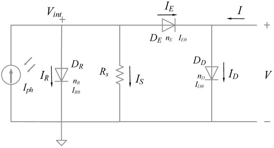
Figure 1.
Our previous lumped-parameter equivalent circuit of organic solar cells (OSCs).
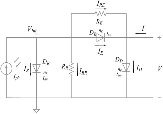
Figure 2.
Improved lumped-parameter equivalent circuit of OSCs.
Based on Kirchhoff’s current law at two earth-free nodes in Figure 2, we can obtain
Subsequently, we substitute Ohm’s law and Shockley’s ideal diode current equation [21] into (1) and (2), yielding
In (3) and (4), ID0, IR0, and IE0 are the reverse saturation currents of three diodes. nD, nR, and nE are the ideality factors of three diodes representing the divergence from the ideal diode. Vt is the thermal voltage symbolled by kT/q, where k is the Boltzmann constant, T is the absolute temperature, and q is the electron charge. To derive the solution of the equation set efficiently, we utilize NR method [17,18,19] to get the solution Vint(V) of (1). Subsequently, we substitute Vint(V) into (2) to obtain the results of I(V).
In NR method, we define a function f (Vint), the function’s derivative f ′, and an initial guess Vint(0). Here, f (Vint) is another expression of (3), i.e.,
Repeating the following process, we can derive the asymptotic solution Vint of (3), i.e.,
3. Verification and Discussion
In this section, we verify the accuracy of the improved lumped-parameter circuit solution by using the method of least squares and validate the practicability of the circuit model by using the reconstructed experiment data [20]. Furthermore, we compare our solution with our previous model [17] and then discuss about the reason why the improved solution is more accurate.
3.1. Numerical Verification and Effect of Individual Parameters
As shown in Figure 3, Figure 4, Figure 5, Figure 6, Figure 7, Figure 8 and Figure 9, the solutions derived by NR method agree with the method of least squares. It is noted that we use the same fitting parameter as our previous work [17], except for RE, to show that I–V curves simulated by our improved model are able to increase in exponent-like form instead of exponent form in the case of V > Voc.
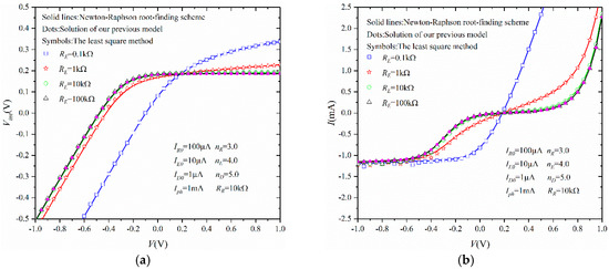
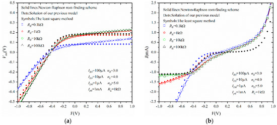


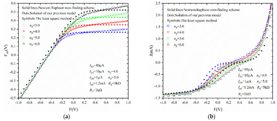
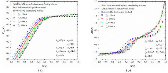

In Figure 3, RE determines the slope of Vint (shown in Figure 3a) in the first quadrant, and the slope of I (shown in Figure 3b) in the first and fourth quadrants. If RE approaches infinity, our improved circuit in Figure 2 would degrade into our previous circuit in Figure 1. If RE approaches zero, the I–V characteristic becomes J-shaped, and the model becomes a two-diode model. On the contrary, as shown in Figure 4, in the third quadrant, RR determines the slopes of Vint(V) (shown in Figure 4a) and I(V) (shown in Figure 4b). Figure 5 shows that the constant photogenerated current Iph determines I(V) in the third quadrant. Next, as shown in Figure 6, Figure 7, Figure 8 and Figure 9, both nR and IR0 related to the recombination current can affect Vint(V) in the first quadrant and I(V) in the third quadrant, while both nE and IE0 related to the extraction current can affect Vint(V) and I(V) only in the third quadrant.
From the physical meaning aspect, the extraction current is described by both DE and RE in our improved model. Compared with IE described by only DE in Mazhari’s model [15] and our previous model [17,19], the extraction current in our lumped-parameter equivalent circuit of Figure 2 is the sum of IRE and IE. Firstly, we show the effects from RE on I–V curves in Figure 3. On the condition that RE is enough small, i.e., , the I–V curve would transfer from S-shape to J-shape. At this time, the I–V curve submits to a linear-like rise in the first quadrant. On the condition that RE is large, i.e., , an S-shape appears in the I–V curve. At this time, the I–V curve submits to an exponent-like rise in the first quadrant. In fact, RE play an important role in determining the quantities and shapes of Vint(V) and I(V). It is noted that RE affects Vint(V) and I(V) curves in all of four quadrants. Especially, if RE approaches infinity, the improved circuit in Figure 2 would be transformed into the previous circuit in Figure 1. In Figure 8 and Figure 9, the influences from IE0 and nE on Vint(V) and I(V) are shown, and it is concluded that DE only influences Vint(V) and I(V) in the third quadrant. It is noted that large IE0 values and small nE values lead to a large extraction current in Figure 2. As a result, both diode DE and shunt resistance RE are used to describe the extraction current in Figure 2. In other words, this is the key point, assuring that our improved circuit in Figure 2 can demonstrate I–V kinks with exponent-like rises instead of exponent rises [15,17,19].
From the mathematical computation aspect, although we also used NR method in our manuscript like our previous work [17,18], the simulations of our improved lumped-parameter circuit for I–V characteristics of OSCs are obviously more accurate than our previous equivalent circuit of OSCs [17], as shown in Figure 3, Figure 4, Figure 5, Figure 6, Figure 7, Figure 8 and Figure 9. Except for RE, the other fitting parameters used in simulations are the same as those in our previous work [17]. The reason is that the same parameters facilitate us to compare our improved model with our previous model [17]. According to Figure 3, Figure 4, Figure 5, Figure 6, Figure 7, Figure 8 and Figure 9, we can observe that I–V curves plotted by our improved circuit in Figure 2 can increase in exponent-like form kinks instead of exponent form kinks, simulated by our previous circuit [17] in Figure 1.
3.2. Comparison with Reconstructed Experimental Data and Our Previous Model
As shown in Figure 10, we validate our model by comparing the solutions to our improved circuit (shown as solid lines) with reconstructed experimental data (shown as symbols) [20]. The model parameters of simulations are given in Table 1 for the improved circuit in Figure 2 and Table 2 for the previous circuit [17] in Figure 1. To show the difference between our improved and previous circuits, the solutions of our previous model (dashed line) are also shown in Figure 10. For organic solar cells in [20], bilayer films, i.e., the fullerene C60 and the purified poly[2-methoxy-5-(2-ethylhexyloxy)-1,4-phenylene-vinylene] serving as electron acceptor and donor, are prepared on clean ITO glass coated with 50 nm of PEDOT:PSS and Al cathode. In N2 atmosphere, under 1000 W/m2 simulated AM1.5G sunlight, the I–V characteristics of solar cells in [20] were measured. Experimental results are shown as symbols in Figure 10.
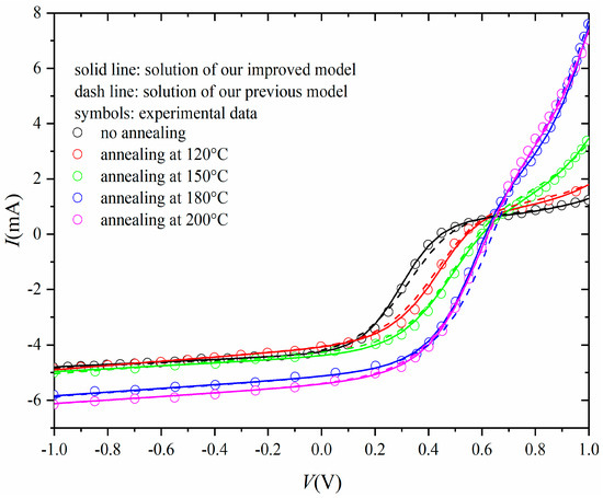
Figure 10.
Comparisons between simulation results of our improved circuit with our previous circuit [17] and reconstructed experimental data [20].

Table 1.
Model parameters used in simulations of our improved circuit in Figure 2.

Table 2.
Model parameters used in simulations of our previous model [17] in Figure 1.
In Figure 10, we observe that the I–V curves of our previous model [17] do not agree with the experiment data very well, especially for the case of V > 0 V. On the one hand, the slope of S-shaped I–V curves simulated by our previous model [17] in the fourth quadrant are always lower than reconstructed experimental data. On the contrary, our solutions of the improved equivalent circuit model show excellent agreement with the experimental results, because both RE and DE in Figure 2 represent extraction of free carriers. It is obvious that our improved circuit can describe I–V characteristics more accurately in the first and fourth quadrants, which reduces simulation errors compared with our previous model [17] due to the addition of RE. On the other hand, according to Figure 10, we can observe that the power conversion efficiency (PCE) calculated from the I–V curves in the fourth quadrant, the I–V kinks plotted by the I–V curves in the first quadrant, and the photogenerated current Iph ensured by the current intercept of the I–V curves in the third quadrant increase as the annealing temperature increases. In fact, the decrease of annealing temperature leads to solar cell devices’ degradations. That would also be shown in the changes of model parameter values in Table 2, in particular, of RE, RR, and Iph. Firstly, in the first quadrant, the I–V kinks are restrained because of the annealing temperature reduction. Correspondingly, the value of RE increases in accordance with the annealing temperature reduction. This is also consistent with device physics, that RE is relative to the extraction current of OSCs. Secondly, in the third quadrant, Iph is determined and shows positive correlation with the annealing temperature. Thirdly, in the fourth quadrant, RR also has positive correlation with the annealing temperature and determines the value of the recombination current where the large value of RR is corresponding with large PCE and fill-factor (FF).
4. Conclusions
In this paper, a lumped-parameter equivalent circuit of organic solar cells (OSCs) is improved from Mazhari’s and our previous circuits by adding a shunt resistor RE in parallel with diode DE. From the circuit topological structure aspect, the addition of RE provided in our manuscript is a minor but very important revision for increasing the accuracy of simulations for I–V characteristics of OSCs in the first and fourth quadrants. From a physical meaning aspect, both shunt resistance RE and diode DE represent the extraction current, aiming at simulating the exponent-like kink in the first and fourth quadrants. From the mathematical simulation result aspect, we use the Newton–Raphson method to solve the I–V solution of our improved circuit and verify it by using the least square method results and reconstructed experimental data.
Author Contributions
T.W., C.X. and F.Y. conceived the paper, designed and performed the simulations; T.W. wrote the paper; C.X. and F.Y. revised the paper, G.H. and W.L. finally analyzed the data; C.X. and G.H. contributed to analysis tools.
Funding
This work was funded in part by the Scientific Research Funds of Huaqiao University under grant 16BS706 and in part by the Scientific Research Funds for the Young Teachers of Fujian Province under grant JAT170034.
Conflicts of Interest
The authors declare no conflict of interest.
References
- Tran, V.H.; Ambade, R.B.; Ambade, S.B.; Lee, S.H.; Lee, I.H. Low-temperature solution-processed SnO2 nanoparticles as cathode buffer layer for inverted organic solar cells. ACS Appl. Mater. Interfaces 2017, 9, 1645–1653. [Google Scholar] [CrossRef] [PubMed]
- Kim, T.; Kim, J.-H.; Kang, T.E.; Lee, C.; Shin, M.; Wang, C.; Ma, B.; Jeong, U.; Kim, T.-S.; Kim, B. Highly efficient all-polymer solar cells. Nat. Commun. 2015, 6, 8547. [Google Scholar] [CrossRef] [PubMed]
- He, Z.; Zhong, C.; Su, S.; Xu, M.; Wu, H.; Cao, Y. Enhanced power-conversion efficiency in polymer solar cells using an inverted device structure. Nat. Photonic 2012, 6, 591–595. [Google Scholar] [CrossRef]
- Petti, L.; Munzenrieder, N.; Vogt, C.; Faber, H.; Buthe, L.; Cantarella, G. Metal oxide semiconductor thin-film transistors for flexible electronics. Appl. Phys. Rev. 2016, 3, 021303. [Google Scholar] [CrossRef]
- Garcia-Sanchez, F.J.; Romero, B.; Lugo-Munoz, D.C.; Pozo, G.D.; Arredondo, B.; Liou, J.J.; Ortiz-Conde, A. Modelling Solar Cell S-Shaped I-V Characteristics with DC Lumped-Parameter Equivalent Circuits—A Review. Facta Univ. Ser. 2017, 30, 327–350. [Google Scholar] [CrossRef]
- Khanna, V.; Das, B.K.; Bisht, D.; Vandana; Singh, P.K. A Three Diode Model for Industrial Solar Cells and Estimation of Solar Cell Parameters Using PSO Algorithm. Renew. Energy 2015, 78, 105–113. [Google Scholar] [CrossRef]
- Liu, Y.; Zhao, J.; Li, Z.; Mu, C.; Ma, W.; Hu, H.; Jiang, K.; Lin, H.; Ade, H.; Yan, H. Aggregation and morphology control enables multiple cases of high-efficiency polymer solar cells. Nat. Commun. 2014, 5, 5293. [Google Scholar] [CrossRef] [PubMed]
- Chavali, R.V.K.; Li, J.V.; Battaglia, C.; Wolf, S.; Gray, J.L.; Alam, M.A. A generalized theory explains the anomalous Suns–Voc response of Si heterojunction solar cells. IEEE J. Photovolt. 2017, 7, 169–176. [Google Scholar] [CrossRef]
- Kumar, P.; Gaur, A. Model for the J-V characteristics of degraded polymer solar cells. J. Appl. Phys. 2013, 113, 094505. [Google Scholar] [CrossRef]
- García-Sánchez, F.J.; Lugo-Muñoz, D.; Muci, J.; Ortiz-Conde, A. Lumped parameter modeling of organic solar cells’ S-shaped I-V characteristics. IEEE J. Photovolt. 2013, 3, 330–335. [Google Scholar] [CrossRef]
- Zuo, L.; Yao, J.; Li, H.; Chen, H. Assessing the origin of the S-shaped I-V curve in organic solar cells: An improved equivalent circuit model. Sol. Energy Mater. Sol. Cells 2014, 122, 88–93. [Google Scholar] [CrossRef]
- Roland, P.J.; Bhandari, K.P.; Ellingson, R.J. Electronic Circuit Model for Evaluating S-Kink Distorted Current-Voltage Curves. In Proceedings of the Photovoltaic Specialists Conference (PVSC), Portland, OR, USA, 5–10 June 2016; IEEE: Piscataway, NJ, USA, 2016; pp. 3091–3094. [Google Scholar]
- Laudani, A.; Fulginei, F.R.; De Castro, F.; Salvini, A. Irradiance intensity dependence of the lumped parameters of the three diodes model for organic solar cells. Sol. Energy 2018, 163, 526–536. [Google Scholar] [CrossRef]
- Sesa, E.; Vaughan, B.; Krishna, F.; Bilen, C.; Zhou, X.; Belcher, W.; Dastoor, P. A building-block approach to the development of an equivalent circuit model for organic photovoltaic cells. Org. Electron. 2018, 58, 207–215. [Google Scholar] [CrossRef]
- Mazhari, B. An improved solar cell circuit model for organic solar cells. Sol. Energy Mater. Sol. Cells 2006, 90, 1021–1033. [Google Scholar] [CrossRef]
- Romero, B.; Pozo, G.; Arredondo, B.; Martín-Martín, D.; Gordoa, M.P.R.; Pickering, A.; Pérez-Rodríguez, A.; Barrena, E.; García-Sánchez, F.J. S-shaped I–V characteristics of organic solar cells: Solving Mazhari’s lumped-parameter equivalent circuit model. IEEE Trans. Electron. Devices 2017, 64, 4622–4627. [Google Scholar] [CrossRef]
- Huang, G.; Yu, F.; Xu, C. An Analytical Solution to Lumped Parameter Equivalent Circuit Model of Organic Solar Cells. Crystals 2018, 8, 224. [Google Scholar] [CrossRef]
- Xu, C.; Yu, F.; Lin, W.; Huang, G. An Improved Organic Solar Cell Lumped-Parameter Equivalent Circuit Model. Crystals 2018, 8, 277. [Google Scholar] [CrossRef]
- Yu, F.; Huang, G.; Lin, W.; Xu, C. Lumped-Parameter Equivalent Circuit Model for S-Shape Current-Voltage Characteristics of Organic Solar Cells. IEEE Trans. Electron. Devices 2018, 66, 670–677. [Google Scholar] [CrossRef]
- Castro, F.A.; Laudani, A.; Fulginei, F.R.; Salvini, A. An in-depth analysis of the modelling of organic solar cells using multiple-diode circuits. Sol. Energy 2016, 135, 590–597. [Google Scholar] [CrossRef]
- Shockley, W. The theory of p-n junctions in semiconductors and p-n junction transistors. Bell Syst. Tech. J. 1949, 28, 435–489. [Google Scholar] [CrossRef]
© 2019 by the authors. Licensee MDPI, Basel, Switzerland. This article is an open access article distributed under the terms and conditions of the Creative Commons Attribution (CC BY) license (http://creativecommons.org/licenses/by/4.0/).