Review

Indentation Plasticity and Fracture Studies of Organic Crystals

by
Sowjanya Mannepalli
and
Kiran S. R. N. Mangalampalli
*
SRM Research Institute, Department of Physics and Nanotechnology, SRM University, Kattankulathur, Chennai 603203, India
*
Author to whom correspondence should be addressed.
Crystals 2017, 7(11), 324; https://doi.org/10.3390/cryst7110324
Submission received: 23 September 2017 / Revised: 18 October 2017 / Accepted: 23 October 2017 / Published: 27 October 2017
(This article belongs to the Special Issue Crystal Indentation Hardness)

Abstract

:
This review article summarizes the recent advances in measuring and understanding the indentation-induced plastic deformation and fracture behavior of single crystals of a wide variety of organic molecules and pharmaceutical compounds. The importance of hardness measurement for molecular crystals at the nanoscale, methods and models used so far to analyze and estimate the hardness of the crystals, factors affecting the indentation hardness of organic crystals, correlation of the mechanical properties to their underlying crystal packing, and fracture toughness studies of molecular crystals are reviewed.

Graphical Abstract

1. Introduction

The crystals of organic molecules offer attractive physical properties that are different from the thermal, mechanical, optical, and electronic properties of conventional solids because of the presence of weak intermolecular interactions (such as van der Waals and dipole interactions, etc.) and the interplay between inter-and intramolecular degrees of freedom [1,2]. During the last decade, understanding the physics and mechanical deformation behavior of single crystals of organic molecules has become the subject of both theoretical and experimental researchers with the intention of exploring and exploiting them for various technological [2] applications such as molecular electronics [3] and pharmaceutics [4,5,6,7,8,9,10,11], etc. [12,13]. For example, in the pharmaceutical industry, the easy tableting and formulation of a drug solely depend on the mechanical properties of the bulk drug. Therefore, the establishment of structure-mechanical property relationships is key to designing and controlling the properties of molecular crystals in a more effective way [14]. In this review article, the authors have made efforts to summarize the recent advances in measuring and understanding the indentation-induced plastic deformation and fracture behavior of single crystals of a wide variety of organic molecules and pharmaceutical compounds, including the importance of hardness, H, measurement at the nanoscale, methods and models proposed and/or utilized to analyze and estimate the H of the crystals, factors affecting the H of organic crystals during small-scale testing, correlation of the mechanical properties to their underlying crystal packing, and fracture toughness studies.

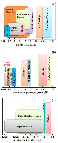
1.1. Mechanical Properties

The mechanical properties of materials refer to the behavior of materials when external forces are applied. Knowledge of this area provides the basis for designing molecular solids with desirable properties and avoids failures in several engineering applications. The core concern in design to prevent structural failure is that the applied stress (force/unit area) must not exceed the strength of the crystals; otherwise, it leads to deformation or fracture failure. Deformation failure can be understood as the change in the physical dimensions or shape of crystals which cannot be recovered. When the cracking reaches to the extent that separates the crystal into two pieces, is called a fracture. So far, material failures are classified either as deformation or fracture. Deformation has been further classified as elastic and plastic upon loading. As the name indicates, elastic deformation recovers immediately upon unloading. In general, stress and strain are proportional to each other in the case of pure elastic materials. The proportionality constant, E, is the modulus of elasticity for axial loading cases. In contrast, plastic deformation is a permanent deformation process and does not recover upon unloading. Once plasticity is initiated in the material, an additional increase in stress causes further deformation, called yielding, and the beginning point of that process is known as the yield strength, σo. Based on the plastic deformation behavior in various materials, materials are recognized as ductile or brittle. While ductile materials are capable of sustaining large amounts of plastic deformation, brittle materials fracture without entering much into plastic deformation. While many metals exhibit ductile behavior, glasses, molecular crystals, and ceramics show brittle behavior. Materials having high values of both ultimate tensile strength, σu, and strain at fracture, εf, are recognized as tough, and these are desirable for use in structural applications. The plastic deformation that accumulates with time is termed creep [15].

1.2. Plasticity

Most real materials undergo some permanent deformation upon loading, which involves dissipation of energy. This means that the original state may be achieved by the supply of more energy, as the process is irreversible. In crystalline materials and metals, the motion of dislocations and the migration of grain boundaries are responsible for microscale level plastic deformations [16]. The theory of plasticity was initially developed by Tresca [17], who proposed yield criterion in 1864. Saint-Venant [18], Levy [19], Von Mises [20], and Hencky and Prandtl [21] have further advanced the concept of yield and plastic flow rules. Later, Prager [22] and Hill [23] developed the “classical theory” which brought many aspects into a single framework. Further developments in computational and numerical methods [24] have been developed for a better understanding of the plasticity problem in crystalline materials.
It was proposed that plastic flow occurs in molecular crystals via a slip mechanism (movement of edge dislocations) along with specific directions in the crystal [25]. Interestingly, while the dislocation climb was reported as the responsible deformation mechanism during creep for molecular crystals at elevated stresses and temperatures, edge dislocation movement under applied stress was found as the dominant deformation mechanism for plastic crystals. Since pharmaceutical industries use techniques like grinding, milling, and tableting to make tablets, the solids that deform plastically via edge dislocation movement or slip are given importance to develop a predictive approach to the yield properties of molecular crystals/compounds [26].

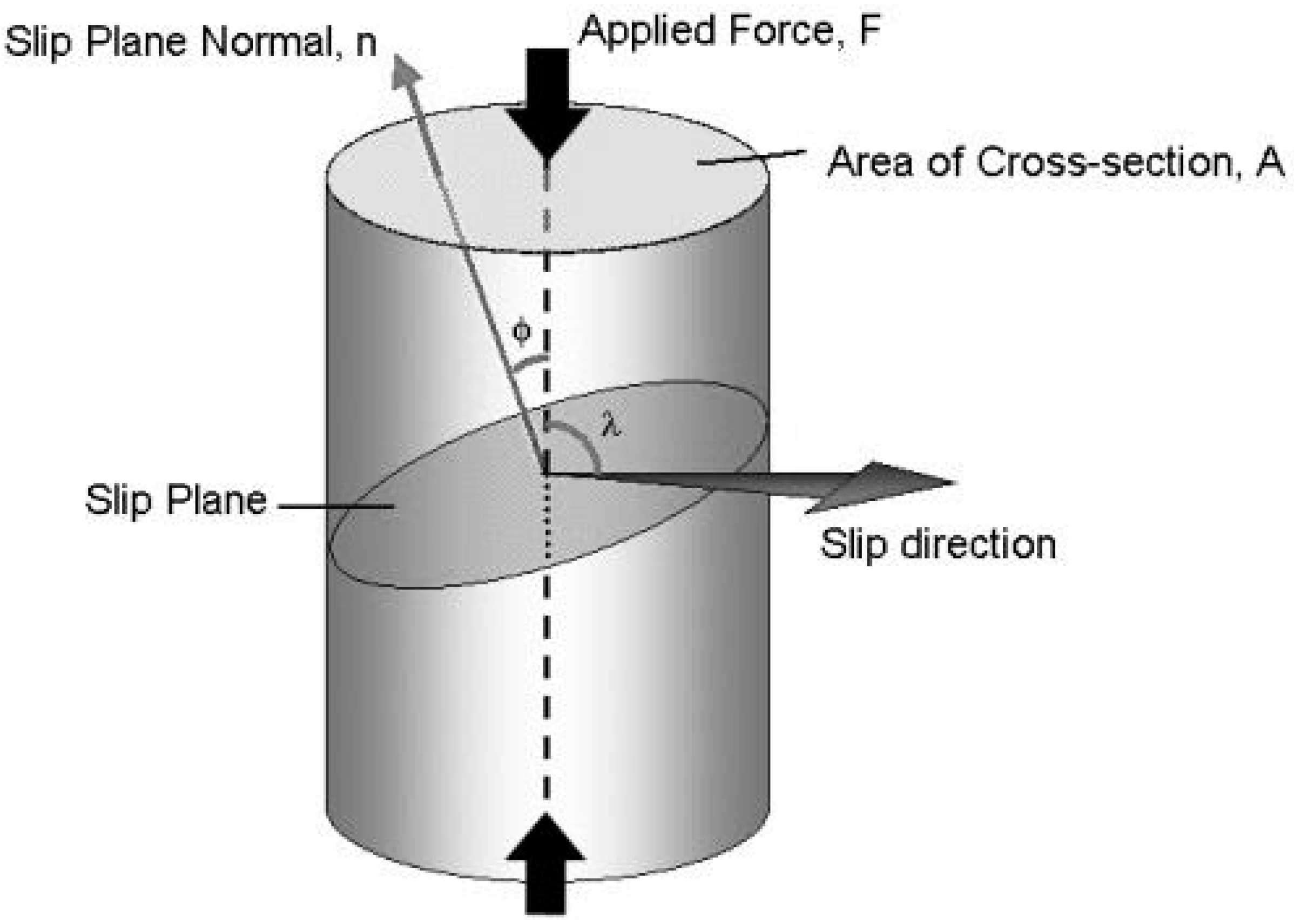
1.3. The Critical Resolved Shear Stress and Schmid Factor

As discussed above, slip along a crystallographic plane occurs via a dislocation motion for which a certain amount of stress is needed to overcome the resistance offered by the lattice. It is observed that the slip in a particular crystallographic plane occurs when the shear stress along the slip direction reaches a critical value on that particular plane. Therefore, this critical shear stress is related to the stress required to move dislocations across the slip plane. The yield stress (stress required to onset the plastic deformation under a tensile/compressive load) can be related to the shear stress that acts along the slip direction, as below [15]:
τ = σ   c o s   c o s λ
where σ = FA is the applied tensile/compressive stress. If this is applied along the long axis of the sample with cross-sectional area A (as shown in Figure 1), then the applied force along that axis is F = σA.
The slip direction is shown in Figure 1 if the slip occurs on the plane that is shown in the schematic with plane normal n. The resolved shear stress acting parallel to the slip direction on the slip plane, τR, can be calculated using the following equation [15]:
τ R =   r e s o l v e d   f o r c e   a c t i n g   o n   t h e   s l i p   p l a n e a r e a   o f   s l i p   p l a n e =   F c o s λ A / c o s ϕ = F A c o s λ c o s ϕ
where ϕ, the angle between the force axis and the slip plane normal and λ is the angle between the force axis and slip direction. The Fcosλ term represents the axial force that lies parallel to the slip direction. The value of τR at which slip occurs in a given crystal with specified density of dislocations is constant, and is known as critical resolved shear stress, τc. This is also known as Schmid’s Law. The quantity, cos φ cos λ is called Schmid factor. Schmid’s law can be written as [15]:
τ c =   σ y c o s ϕ c o s λ
where σy is known as yield stress, the stress required to cause slip on the primary slip system. There can be several slip systems in a given crystal. As the load increases, the τR on each slip system increases until it reaches τc. When the particular slip system reaches τc, the crystal begins to deform plastically by that slip system, hence known as the primary slip system. With the further increase of load, other slip systems may begin to operate when τc is reached. Schmid’s law can be used to calculate the Schmid factor to estimate the primary slip system in a given crystal. The primary slip system will have the greatest Schmid factor. One can calculate the Schmid factor for every slip system in the given material to determine which slip system operates first [15].

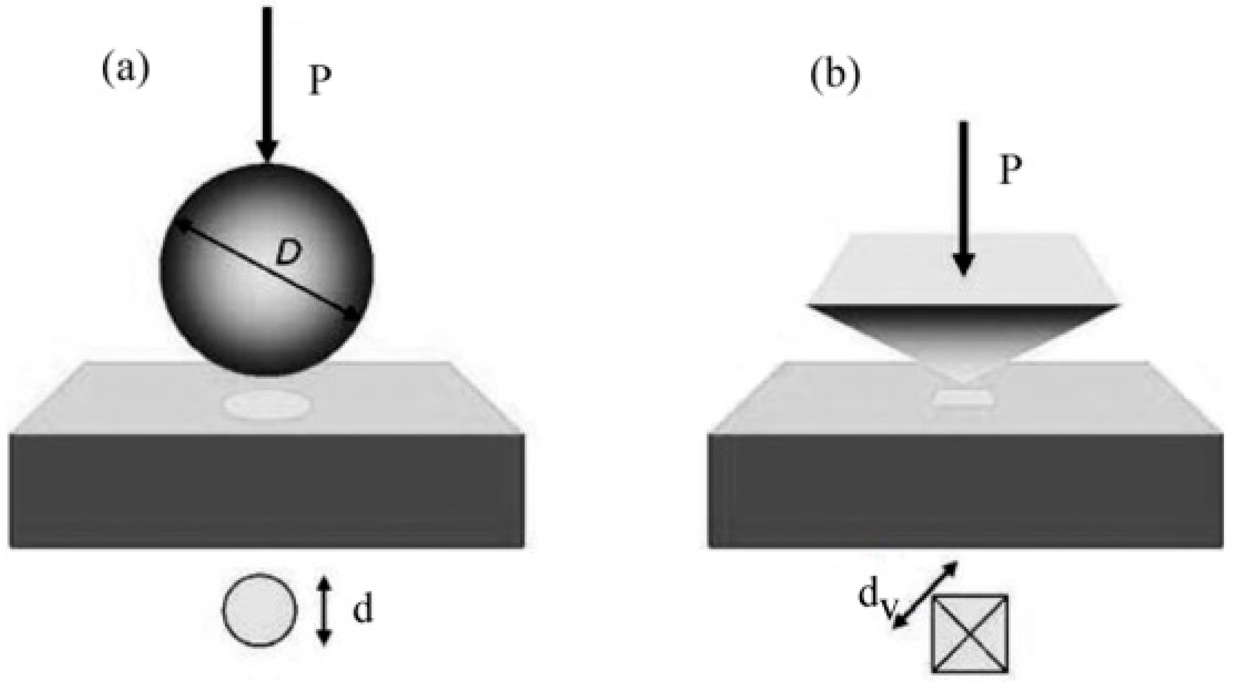
2. Hardness Measurement Methods

Hardness testing is performed to estimate the materials’ ability to resist plastic flow under applied load. However, the measurement of H depends on the method one chooses and is influenced by both the elastic and plastic nature of materials. Depending on the forces applied and displacements obtained, the H measurements can be defined as micro-, nano-, or macrohardness. While measuring macrohardness is very simple for bulk materials, thin films and microstructured materials require H measurement techniques at micro/nanoscale [27]. While the electromagnetic, ultrasonic, and rebound techniques are used to measure materials’ hardness, indentation testing has received considerable attention because it is non-destructive and provides reliable and straightforward data. Indentation (penetration of a hard material, typically a diamond with a known geometry, into the sample) tests were first performed by Brinell [28], who used spherical balls (as shown in Figure 2a) from hardened steel ball bearings or made of cemented tungsten carbide to quantify the plastic properties of materials in 1900. Brinell’s work was then followed and improved by Meyer [29] in 1908.
In Meyer’s work, the H was calculated using the ratio between the load (P) and the projected area (A), namely, H = P/A. In 1922, the Vickers [30] test was carried out using a square-based pyramid diamond indenter with a 136° semi-angle instead of a ball indenter, as shown in Figure 2b. The Vickers hardness was defined as the ratio between the load and the surface area of the residual impression, namely, Hv = 1.8544 P2/dv2, where dV is the length of the diagonal of the surface area. A research paper published by Tabor [31] in 1948 advanced the understanding of indentation hardness testing, wherein he described the penetration procedure of a ball-like indenter into a material. He mentioned that, upon the application of the load, the material initially starts deforming elastically (which means that the material recovers to its original state upon removing the load) and then flows plastically (associated with work hardening mechanism after removal of the complete load). In 1951 [32], he proposed an equation relating indentation hardness and the yield stress (σ) of the material based on the theory of indentation of a rigid perfectly plastic solid, namely, H = C σ, where C is a constant that is dependent on the indenter geometry. Tabor furthered the understanding of the indentation response of polymers [33,34] and brittle materials [35], as well as the temperature dependence of the hardness [36] of metal oxide samples. Within a short time, the indentation technique was extended to small volume materials in the mid-1970s [37]. The indentation technique that helps in measuring the mechanical properties of small volume materials was named “nanoindentation”, as the length scale of the penetration depth is usually in nanometers. In the indentation methods mentioned above, the contact area was directly measured from the residual impression area. However, in nanoindentation, since the contact area, Ac, of the residual indent is too small to measure, Ac is determined by the measured depth of penetration in nanoindentation [38].
The indentation technique became popular after 1992 with the development of a method to measure elastic modulus and hardness based on the load, P, and displacement, h, curve. Oliver and Pharr [39,40] proposed this approach in 1992. In 2007, Kucharski and Mroz [41] developed a procedure for determining stress-strain curves using cyclic spherical indentation data. Subsequently, Kruzic et al. [42] developed a method to evaluate the fracture toughness of brittle materials. Further developments, such as identifying the effects of kinematic hardening on the material response [43], the reconstruction of the axial stress-strain curve from the indentation data with conical indenter over a range of cone angles [44], and the modification of the hardness formulation within the elastic-plastic transition derived for solids, were reported by Hill [23] and Marsh [45]. Rodriguez et al. [46] found that the mechanical properties of alumina-titania nanostructured films measured using nanoindentation were higher than the conventionally measured values.
The hardness obtained by the indentation test is defined as the ratio of the maximum indentation load, Pmax, to the contact area, of the indenter [39,40]:
H = P max A c ( h c )
The reader should note that the above definition of indentation hardness may deviate from the traditional hardness measurement where the area is estimated from the residual indent impression. In the latter process, the actual contact area may be underestimated if there is significant elastic recovery during indentation unloading. In general, the materials with high elastic modulus will exhibit slightly deviated values from the indentation hardness measurement.
The area of contact is a function of the indenter contact depth, hc, and can be determined by the following expression:
A c ( h c ) = C 0 h c 2 + C 1 h c + C 2 h c 1 / 2 + C 3 h c 1 / 4 + ........ + C 8 h c 1 / 128
It is important to note that only the C0 will be used if the Berkovich indenter is assumed as a perfect tip at higher penetration depths. For the cases of imperfect tips and shallower depths, higher-order terms have to be considered, and these can be obtained from the fit of the tip area function curve for a given tip. The hc can be estimated from the P-h curve, as shown in Figure 3 [39,40]:
h c = h max ε P max S
where hmax is the maximum indentation depth, and 0.75(P/S) denotes the extent of the elastic recovery (he) [39,40]. Here, the stiffness S = dP/dh and ε is a constant that depends on the indenter geometry. The values of ε are 0.72, 0.75, and 1.00 for conospherical, Berkovich, and flat punch tips, respectively.
The maximum shear stress, τmax [47,48], the stress required to nucleate dislocations, can be estimated using the following equation when the load-displacement curve exhibits a pop-in (i.e., a clear transition between elastic and plastic deformation):
τmax = 0.31 (6Er23R2)1/3 Pmax1/3
where Er is the reduced modulus, R is the radius of the indenter, and Pmax represents the peak load.

2.1. Prediction of Hardness Using Crystal Morphology

Roberts and Rowe [26] developed a model to predict indentation hardness of molecular single crystals based on cohesive energy density, the weakest planes from the crystals structures, and structural parameters. The equation of hardness is given as [26]:
H = ( c 1 c 2 F a 2 N A R c 2 S r 3 Z ) C E D
where Sr is the slip ration, c1 and c2 are unit cell constants, NA is Avogadro’s number, Rc is the length of the cell, Z is the number of molecules in a unit cell, and Fa is an angular function related to α, β, and γ depending on the crystal class. CED is the Cohesive Energy Density. Since most of the organic crystals crystallize in monoclinic structure, the above equation can be re-written as [26]:
H = ( b c s i n β 2 N A a 2 S r 3 Z ) C E D
For a monoclinic system, Fa = sinβ; if Rc = a, then c1 = b and c2 = c. Therefore, the above equations can be utilized to predict the indentation hardness from the cohesive energy density. Two slip ratios are used, Sr of 0.7070 and 1 [26]. For orthorhombic systems, Fa = 1 in the above equation [26].

2.2. Factors Affecting Nanoindentation Hardness of Organic Crystals

Several factors, such as indenter calibrations, vibration during testing, indenter shape, indentation size effects [49], thermal drift [49], machine compliance [38,49], and pile-up/sink-in [38,49], etc., affect indentation hardness values severely during the testing of molecular crystals.
Thermal drift occurs during nanoindentation either due to creep (time-dependent plasticity at a constant load) within the sample caused by plastic flow or due to variation in the transducer dimensions due to temperature change-induced contraction or expansion. The latter method causes a change in the real-time penetration depth measurement under a constant Pmax which is difficult to distinguish from the creep. However, these depth changes result in a thermal drift error on the actual penetration depth. Fisher-Cripps [38] reported that the temperature rises to 100 °C within the specimen during indentation. Although the change in the linear dimension of the specimen will be significantly smaller compared to the total penetration depth, the localized rise in temperature to 100 °C within the sample affects the viscosity and indentation hardness of the test specimen. The drift effect can be corrected by adjusting the penetration depth, if the drift rates are determined during indentation. The drift rates can be captured at the peak load. For calculating the drift rates, the data at the final unload increment can be used because creep is less likely to occur at low loads.
Another critical care to be taken during indenting molecular crystals is to provide the correct compliance value of the instrument, which is defined as the deflection in the load frame, shaft of the indenter, and sample mount. Since molecular crystals are relatively soft compared to inorganic materials, mechanical polishing of the crystals and mounting crystals in the acrylic resin is impossible. Therefore, most of the researchers use cyanoacrylate glue for firm mounting of the crystals for nanoindentation. When the load is applied, the elastic deformation in both the crystal surface and some parts of the testing machine cause an increase in the measured indentation depth that is not experienced at the indentation contact [38]. The compliance can be quantified as the ratio of the instrument’s deflection to the applied load. The stiffness measured by the unloading portion of the P-h curve is the result of the elastic deformation behavior of both the sample and load frame. The total compliance of the machine can be obtained by adding the compliances of the specimen, indenter, and load frame. The crystal compliance can be minimized by mounting them firmly to the substrate.
To measure precise indentation hardness, finding the contact area of the indent using the residual/final penetration depth is very important. To measure such contact area, the indenter geometry should be well explored and ideally flawless, which is not common. To estimate the actual contact area of the indenter, either Atomic Force Microscope (AFM) or Scanning Electron Microscope (SEM) can be utilized, and correction can be done by dividing the real Ac of the tip. If the ratio of the real and actual Ac is greater than one, the actual indenter has a higher tip radius than the actual tip, which leads to larger contact areas at lower penetration depths [38].
Surface roughness, ρ, plays an important role in determining the mechanical behavior of materials. In general, the surface roughness should be as small as 5% of the maximum indentation depth in order to achieve reliable mechanical properties. Shibutani et al. [50] experimentally investigated the effect of ρ on pop-ins observed in nanoindentation using single-crystalline Al and found that the critical values of the load at the pop-ins are sensitive to ρ. Their results show that the first pop-in with a higher width occurs in the smoother sample at higher loads than the rough sample [38].
The determination of contact area by SEM and AFM imaging methods can go wrong if the sample surface is not aligned normal to the indenter tip. Since molecular crystals cannot be polished mechanically to obtain the flat surface, it is important to choose perfectly flat samples for nanoindentation. Otherwise, H and Er values may be wrongly estimated because of the incorrect Ac estimation. Since it is highly impossible to obtain a 100% orthogonality condition between the sample surface and the indenter tip, one relaxation is allowed [51].
Significant pile-up and sink-in around the residual indent are observed earlier for plastically deformed materials. Such effects were found to depend on the ratio of modulus to yield stress as well as on the level of strain hardening of the sample material [38]. A relationship between the residual indentation depth and the total penetration depth also provides reliable information about these phenomena. If the ratio between the residual depth and the total depth is greater than 0.7, pile-up can be expected; otherwise, sink-in can be expected. The presence of pile-up around the residual indent causes the underestimation of the Ac and hence higher hardness [52]. When there is a pile-up around the indent, the Oliver-Pharr [39] method overestimates the H and Er values (up to 60 and 30%, respectively) because their evaluation depends on the Ac deduced from the P-h data. Several models are available to determine the pile-up effect, such as the semi-ellipse method [53], the method put forth by Choi, Lee, and Kwon [54], and the finite element method [55]. Zhou et al. [56] estimated the pile-up free hardness (H actual) and elastic modulus (E actual) values using the ratio of pile-up height (hpile-up) and contact depth (hc). The equations are:
H a c t u a l = H O & P ( 1 + h p i l e u p h c ) 2
E a c t u a l = E O & P ( 1 + h p i l e u p h c ) 1
where HO&P and EO&P are the hardness and elastic modulus obtained using the Oliver-Pharr method [39,40], respectively. The dramatic increase of hardness with decreasing indenter penetration depth is known as indentation size effect (ISE). In crystalline materials, ISE was explained using the concept of geometrically necessary dislocations (GNDs), as proposed by Nix and Gao [57]. Recently, Arief et al. [58] showed, using a scanning X-ray microdiffraction technique on Cu (111) crystals at various indentation depths, that the density of GNDs increased with decreasing indentation depth. The ISE can also be due to the incorrect estimation of the Ac of the indent at shallow depths. For example, although the three-sided pyramidal Berkovich indenter is considered to be sharp and researchers use the area function of a sharp tip to estimate the contact area, the tip is not atomically sharp, as it always ends with a spherical shape. Therefore, at shallow depths, the area function of a Berkovich indenter underestimates the actual Ac to its corresponding depth, and thus measures higher H values.

3. Understanding the Plastic Behavior of Organic Crystals

Plastic bending experiments were conducted by Reddy et al. [59,60,61] to understand the plastic behavior of organic crystals, and they observed that molecular crystals undergo plastic deformation if and only if the intermolecular interactions strength in orthogonal directions is significantly different, and that there exists a correlation between bending and crystal packing (see Figure 4a,b). Based on that observation, molecular crystals were classified as plastic or brittle, and a model was developed for bending crystals. While the former crystals are bendable, the latter cannot be deformed plastically. Further, Reddy and Naumov [62] studied the plastic deformation mechanism in hexachlorobenzene crystals and observed changes in the unit cells parameters in the region of deformation, as shown in Figure 4c. In contrast to inorganic plastic materials, such as metals etc., no volume change including dimensions of crystals and thickness was observed following the bending of molecular crystals. However, crystals that have “cross-linked” intermolecular interactions in three orthogonal directions are hard and brittle. Recently, Sajesh et al. [63] examined the plastic bending mechanism in Dimythl Sulfone (DMS) using a new bending model that provides quantitative rationalization based on differential binding and the stacking of molecular layers in orthogonal directions.
Saha and Desiraju [64] reported a method to design hand-twisted helical crystals from plastic crystals using crystal engineering techniques (see Figure 5). The procedure was started with a 1-D plastic crystal (1,4-dibromobenzene), which was then converted to a 1-D elastic crystal (4-bromophenyl 4’-chlorobenzoate). This was achieved by introducing a molecular synthon-O-CO- in place of the supramolecular synthon Br···Br in the precursor. The 1-D elastic crystal was then modified into a 2-D elastic crystal (4-bromophenyl 4’-nitrobenzoate). These 2-D elastic crystals were then transformed into 2-D plastic crystals (4-chlorophenyl and 4-bromophenyl 4’-nitrobenzoate) with two pairs of bendable faces without slip planes by varying interaction strengths. The presence of two pairs of bendable faces which are orthogonal to each other allowed the crystals to hand twist in a helical shape [64]. This shows that prior knowledge of the structure-mechanical properties of molecular crystals such as plastic and elastic mechanical deformation are necessary to engineer the molecular crystals with desired properties.

3.1. Indentation Hardness of Molecular Crystals

3.1.1. Cyclotrimethylenetrinitramine, (RDX) Crystals

Hagan and Chaudhri (1977) [65] measured the Vickers hardness of 24.1 kg/mm2 for RDX single crystals between loads varied from 150 to 700 mN. Even at the smaller loads cracks have been observed. The fracture surface energy was estimated as 0.11 J/m2 and 0.07 J/m2 for two cleavage planes. Halfpenny et al. [66] and Chaudhri [67] measured Vickers hardness to 39 kg/mm2 and 21 MPa, respectively, and found that the primary dislocation motion was in the (010) planes. Elban et al. [68] reported that the Vickers microhardness value varied from 310 to 380 MPa for various growth faces of RDX crystals (50-gram load). Also, Elban [69] used Knoop hardness methods to measure hardness anisotropy. Hardness varied from 170 to 700 MPa for different crystal facets. Gallagher et al. [70] utilized both microhardness and the Knoop indenter and showed crystals orientation dependency which attributed the variation in hardness for different orientations to the dominant slip system.
Roberts et al. [26] developed a model relating the indentation hardness of molecular solids to the Burgers vector’s length, the cohesive energy density, the weakest plane in the crystals, and the crystals’ structural parameters. The prediction of the hardness was based on the identification of the slip planes that were available in the system, and it was assumed that the primary slip plane was the weakest plane, and energetically it was the preferred slip plane. Several methods, such as attachment energy calculations, cleavage planes, and hydrogen bonding pattern information, have been used to identify the slip planes in organic crystals. It was concluded that the cleavage planes provide direct evidence for the weakest planes, which were also twinning planes, indicative of plastic deformation [26]. It is imporatnt to mention here the work carried out by Sun and Kiang [71] on the accuracy of the slip plane predictions using attachment energy calculations. They considered 14 different organic crystals that exhibited layered strcuture and predicted slip systems by their attachement energy calculations using three different current force fields, which were then compared to those identified by crystal structure visualization. They conclude that 50% of the slip/cleavage predictions were inaccurate.
Ramos et al. [72] employed nanoindentation on different faces of single crystals of RDX crystals with a conical (cone shaped tip with a rounded end) probe with the load varying from 250 µN to 10,000 µN. In general, the conical tip is used to delay the elastic-plastic transition at the shallow depths. However, in the present case, all orientations showed cracks even at very low loads with the conospherical tip. The calculated τmax was within 1/15 to 1/10 of the shear moduli. The indentation hardness was measured between 615 and 672 MPa for different faces. In another study, Ramos et al. [73] revealed that the planes produced by the cleavage method yield at a lower applied stress but the habit planes of the as-grown crystals exhibit yield points near the theoretical shear strength. Weingarten and Sausa [74] studied nanomechanical properties of RDX crystals by the P-h measurements using a Berkovich diamond indenter and molecular dynamics (MD) simulations, and reported that the (210) surface was stiffer than the (001) surface.
The abovementioned experimental techniques, such as microindentation [66], nanoindentation [72], and etch-pitting [75], have revealed the (0 1 0) plane in RDX crystals to be the primary slip plane and [100] to be the cross-slip direction since it is shared by the (01 0), {021}, and {011} planes. The {011} and {021} planes are also considered as additional potential slip planes in RDX crystals. Munday et al. [76] investigated the fracture behavior of various crystal planes in RDX crystals using Rice’s criterion and revealed that the (0 11), (021), (0 10), and (00 1) planes may possess active slip systems. Mathew et al. [77] carried out molecular simulation studies in order to investigate the slip asymmetry in RDX crystals. Their study revealed that: (i) the force needed to move a dislocation in RDX crystals was controlled by the mode of deformation, (ii) slip asymmetry was evident in the (010) slip plane with the lowest Peierls stress and, (iii) such asymmetry in (010) plane was caused due to steric hindrance.
Taw et al. [78] reported the mechanical properties of as-grown, conventionally processed, and sub-millimeter RDX crystals. Nanoindentation was conducted using a Berkovich tip in a low load quasi-static mode. Scanning probe microscopy images of the residual impressions showed no evidence of indentation-induced cracking. The measured mechanical properties such as elastic modulus and hardness were matched with the literature. However, the point of onset of plasticity (yield point) occurred between 0.1 and 0.7 GPa, which indicated that the powders of RDX contained a significant number of dislocation sources that were prevalent in the as-grown RDX crystals.
Liu et al. [79] performed coarse-grained MD simulations of RDX crystals to validate the limited-sample coarse-grained potential. The mechanical properties calculated with the simulations were compared with the experimental results. The deformation behavior of RDX under nanoindentation was revealed by a series of simulations that resembled the experimentally determined deformation behavior of the (100) face. Their study concluded that most of the dislocation loops were found to be parallel to the (001) plane due to the low slip threshold of the (010) [100] active slip system.

3.1.2. Hardness Anisotropy Studies in Some Organic Crystals

Joshi et al. [80] measured the microhardness of anthracene, phenanthrene, and benzoic acid single crystals on the (001) cleavage surfaces. The variation of the hardness with applied load decreased with increasing load. The σy (estimated from the hardness) of phenanthrene was higher compared to anthracene, which was attributed to the geometrical disposition of the molecules in the lattice, despite having similar crystal structures. However, the σy for benzoic acid was observed in between that of anthracene and phenanthrene, due to the occurrence of slip activity along the (010) [010] system. Nevertheless, such slip activity was absent in anthracene and phenanthrene. The authors attribute this observation to the hindrance to glide along the [100] direction and the availability of a large number of molecules in benzoic acid.
Marwaha et al. [81] measured the microhardness of different molecular crystals of anthraquinone, hexamine, and stibene along with anthracene and phenanthrene. Among the five crystals studied, hexamine belongs to the body-centered cubic structure (space group: I 4 ¯ 3 m ), whereas the rest belong to the monoclinic crystal structure of the space group P21/a. The indentations were performed on the (110) face of hexamine and the (001) face of all the other crystals. The study concluded that the active slip systems in monoclinic systems were (20 1 ¯ ) [010] and (100) [010] types, whereas (1 10) (1 11) and (112) (1 11) slip systems were responsible for the plastic deformation in hexamine crystals.
Sgualdino et al. [82] employed the Vickers microhardness test on (100), (001), and (110) facets of sucrose crystals and found that the microhardness correlated well with the attachment energy rather than the surface energy. Elban et al. [83] assessed the fracture behavior of (100) planes of sucrose crystals using Vickers indentation hardness testing, which was related to their attachment energy calculations. Ramos and Bahr [84] performed nanoindentation on (100) and (001) faces of sucrose crystals and reported that hardness anisotropy was not considerably high for both the orientations compared to the anisotropic nature in modulus. In fact, the hardness of the cleavage planes was greater than that of the habit planes, and it was attributed to the surface roughness of the crystals. The elastic-plastic transition point occurred at a maximum applied τ of 1 GPa, and the propagation of plastic deformation was crystal orientation-dependent, as evident from the non-uniform natured pile-up around the residual indent impressions. Previously, sucrose was considered as brittle with a limited number of slip systems, but the nanoindentation studies by Ramos and Bahr [84] revealed the inherent significant plastic deformation mechanism at the nanoscale.
Kiran et al. [85] used the instrumented nanoindentation technique to investigate the mechanical anisotropy and correlate with the intermolecular interactions in saccharin crystals. The active slip system in the saccharin crystal is (100) [011]. Both the (100) and (011) faces were indented with a Berkovich nanoindenter with an in-situ scanning probe microscopy (SPM) imaging capability. On the [100], the molecules (as centrosymmetric NH···O dimmers) stacked down, and make an oblique angle to the (100). Further, the molecules within stacks were stabilized through weak π···π interactions, and adjacent stacks were bound by the CH···O bonds. In contrast, in the (011) plane, stacked dimmers were arranged in a crisscross arrangement and CH···O bonds were arranged at 90° to the (011) (see Figure 6a–e). During indentation, while the loading part of the P-h curve of the (011) face was smooth, several distinct pop-ins were evident on the (100) face, as shown in Figure 5f. Interestingly, the first pop-in width (18 nm) was found to be the integral multiples of the interplanar spacing which was explained using the contact mechanics of a spherical indenter [85]. Further, the plastic deformation was seen on both the faces, even at a load of 0.01 mN, due to the sharp geometry of the indenter tip. While the homogeneous plastic deformation on the (011) face was attributed to the existence of several slip systems that are nearly parallel to the plane of the indentation direction, the discrete plasticity on the (100) was due to the lowest attachment energy slip planes, which act as cleavage planes and are prone to pop-ins due to their higher compressibility. The occurrence of pop-ins on (100) plane was attributed to the disruption of CH···O hydrogen bonds followed by an elastic compression of stacked columns through weak π···π interactions [1]. As a result, the columns broke away. Further, the relationship between the pop-in magnitude and the interplanar spacing was observed and rationlized the results with the aid of indentation contact mechanics. Interestingly, the pop-in magnitude measured to be the intergral multiples of the interplanar spacing. At the higher loads, anisotropic cracking was evident on the (100) planes along the corners of the sharp indenter. Furthermore, pile-up inhomogeneity around the residual indent impression indicated that plastic deformation was crystallographic orientation-dependent.
Zhou et al. [86] made efforts to understand the mechanical anisotropy of 1,1-diamino-2,2-dinitroethylene (FOX-7) energetic crystals, which have wavelike π-stacks (see Figure 7a–c), using nanoindentation and density functional theory (DFT) calculations. As expected, the crystal exhibited distinct mechanical behavior from various faces upon nanoindentation, as shown in Figure 7d. While the hardness and stiffness of the (020) face were the highest, the (002) face exhibited the lowest values. Further, the (002) exhibited significant pile-up around the indent, and no cracking was observed, probably because of its soft and plastic behavior, while the (-101) and (002) faces exhibited cracks but with less pile-up. The observed mechanical anisotropy of (020) was attributed to the wavelike π stacking of FOX-7 molecules along the (020) with the support of hydrogen bonds. The uniaxial compression and shear sliding of the FOX-7 crystals calculated using DFT supported the nanoindentation results [86]. The authors conclude that the wavelike π stacking was responsible for the low impact sensitivity of the 1,1-diamino-2,2-dinitroethylene molecule, rather than the other explosives with distinct packing structures [86].
Mathew and Sewell [87] characterized the temperature dependence of the mechanical response and the very early stages of elastic/plastic deformation in 1,3,5-triamino2,4,6trinitrobenzene (TATB) by simulating nanoindentation using MD simulations. The authors used a rigid, spherical indenter and simulated the displacement-controlled nanoindentation curves on the (100), (010), and (001) planes of TATB. While the initial part of the P-h curves on the (001) basal plane follows Hertzian contact behavior (i.e., elastic), pile-up, kinking and delamination were also evident at the elastic-plastic transition. The nanoindentation hardness of the basal planes was predicted to be 1.02 ± 0.09 GPa. However, nanoindentation on the non-basal faces (100) and (010) exhibited non-Hertzian loading behavior, which was attributed to the “softening” of molecular layers due to elastic bending. In addition, the pile-up height on the non-basal planes was observed to be less significant than that on the basal plane. The anisotropic behavior observed from the basal and non-basal planes was attributed to the heating that developed during indentation, which was found to be higher for the basal plane.
Taw et al. [88] used nanoindentation to measure the elastic and plastic properties of representative as-grown sub-millimeter orthorhombic, monoclinic, and triclinic molecular crystals. So far, researchers have performed nanoindentation on relatively large crystals, but this work used as-grown small crystals for nanoindentation. The as-received molecular crystals of TATB, cyclotetramethylenetetranitramine (HMX), FOX-7, azodiaminoazoxyfurazan (ADAAF), and a trinitrotoluene and 2,4,6,8,10,12-hexanitro-2,4,6,8,10,12-hexaazaisowurtzitane cocrystal (TNT/CL-20) were indented using a Berkovich indenter in this study. The results show that the onset of plasticity on the loading part of the P-h curve occurred consistently at a τ value between 1 and 5% of the elastic modulus in all of the crystal systems studied (see Figure 8). Further, the H to Er ratio observed in this study for different crystal systems suggested that the conventional Berkovich tips failed to generate fully self-similar plastic zones in organic crystals because the H/Er ratio varied in the present case from 0.039 to 0.044, whereas the model for fully plastic indentations of organic crystals suggested that the H/Er ratio should vary between 1 and 3. Therefore, the authors concluded that the indents performed by the Berkovich indenter in this study were more elastic [88].

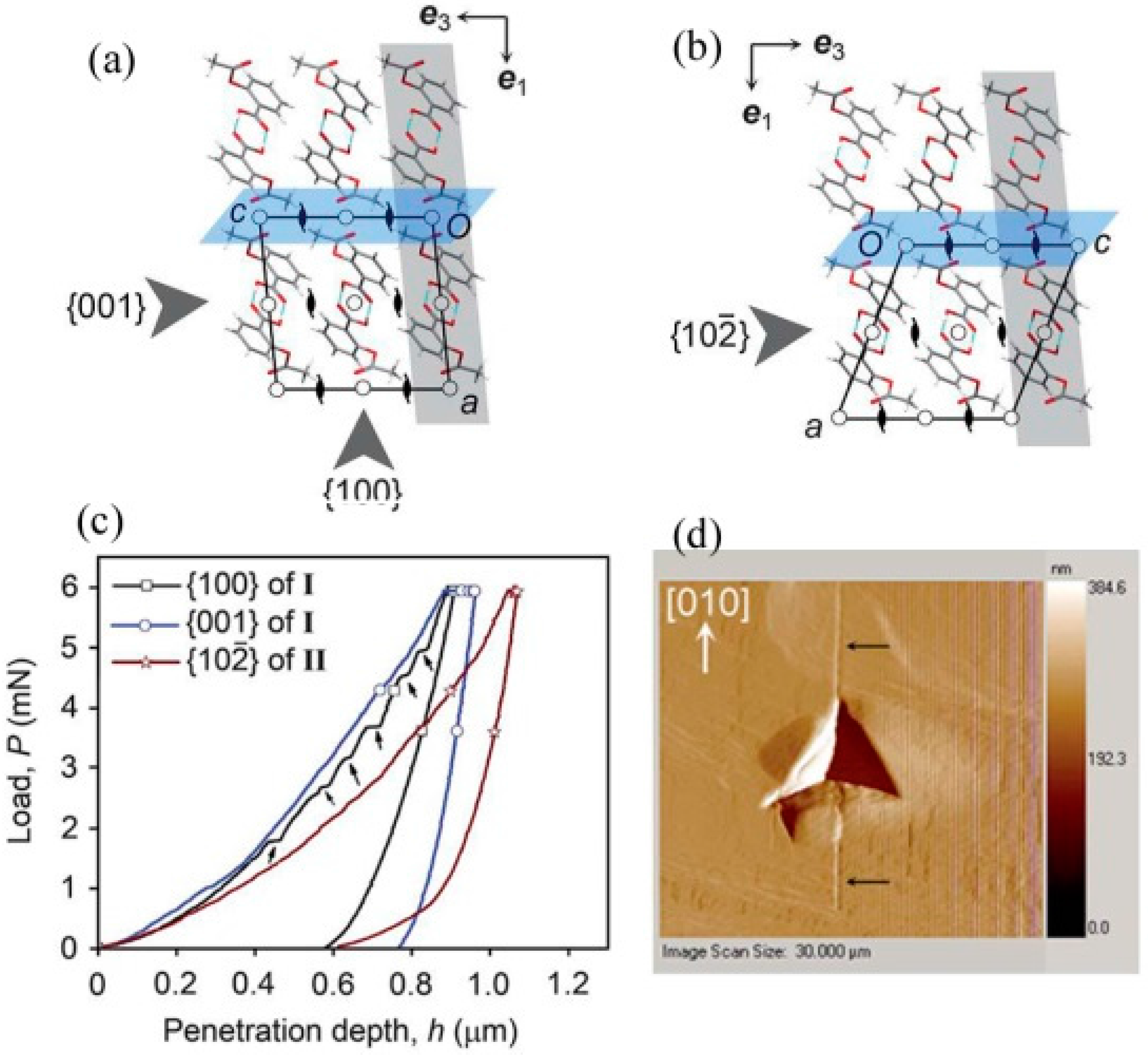
3.1.3. Mechanical Behavior of Aspirin Polymorphs

Varughese et al. [89] utilized the nanoindentation technique to measure the mechanical properties of aspirin polymorphs and to understand the interaction characteristics and instability caused by τ. In both polymorphs, the carboxy groups formed centrosymmetric OH···O dimers and arranged as two-dimensional layers parallel to the (100) [1,89]. Although the crystal structures of the two forms are closely related, two distinct stabilizing CH···O interactions exist in form I [1,89]. They are: (1) the aromatic ring and the acetyl carbonyl group contacts, and (2) the methyl group and ester carbonyl group interactions. In contrast, in form II, the CH···O contacts between acetyl substituents of molecules related by a crystallographic 21 screw axis are the stabilizing interactions across the slip planes. Further, a small shift of adjacent layers parallel to one of the crystallographic axes relates form I and II structures (see Figure 9a,b) [1,89]. Nanoindentation was performed using a Berkovich tip with an end radius of 75 nm on the structurally equivalent {001} face of form I and the {102} face of form II (i.e., the indentation direction is normal to the potential slip planes but parallel to the interlayer shift direction that relates forms I and II). Upon loading, interestingly, while the loading parts of the P-h curves obtained for both the {001} of form I and the {102} of form II are smooth, pop-ins were seen on the {100} of form I, as shown in Figure 9c. The post-indent characterization on the {100} of polymorph I using scanning probe microscopy revealed a fracture along the [010] direction at higher loads, as shown in Figure 9d. Neither fracture nor pile-up was observed for either the {001} of form I or the {102} of form II. The softer nature of form II compared to form I was observed from the hmax. It was observed that the {001} of form I is 37% harder than the {102} of form II. The nanoindentation results justified the solid-state transformation of polymorph II to I if the samples were left under ambient conditions, but the process may be accelerateded with the application of τ.
Olusanmi et al. [90] investigated the anisotropic plastic deformation and fracture behavior of crystals of aspirin form I. While severe fracture was observed on the (001) plane, the (100) plane was found to be more fracture resistant, indicating that the (001) plane is the preferred cleavage plane for aspirin form I (see Figure 10a,b). The measured hardness on the (001) face was reported to be lower than the (100) face, indicating softer nature of the (001) face. Similar to the observation of Varughese et al. [89], pop-ins were noted on both the (001) and (100) faces. However, deeper and more frequent pop-ins were seen on the (100) face. While the pop-ins on the (100) face were associated with cracking, the slip mechanism was responsible for the shallow pop-ins on the (001) face. Therefore, it was suggested that the cleavage planes in aspirin crystals dominate the fracture mechanism under both quasi-static and impact loading conditions.

3.1.4. Mechanoluminiscence Studies in Difluoroavobenzone

Krishna et al. [91] utilized load-controlled Berkovich nanoindentation on single crystals of difluoroavobenzone compounds and investigated their mechanoluminescence properties. The crystal packing of both green and cyan forms are shown in Figure 11a,b. The (100) plane of BF2dbm (tBu)2 crystals was formed by the hydrophobic tBu groups, which allowed for easy plastic deformation through the bending of the (001) face, which makes a 90° angle with the slip plane (100). The H value was found to be higher on the (100) plane when compared to the (001) because a slip in the (001) was easily formed, as the indentation direction was parallel to the slip plane. While the nanoindentaion measured a high hardness value for BF2dbm(OMe)2 crystals, three-point bending experiments revealed its susceptibility to localized plastic deofrmation. This is because the (100) slip plane was parallel to the indentation direction of [010]; therefore, maximum resistance was offered against indentation penetration. In addition, the higher values of plastic and elastic properties were attributed to the strong C-H…F interactions. The third compound, BF2dbmOMe, exhibited lower hardness values than the second compound because the C-H…F interactions were slightly obliquely angled to the direction of indentation. Further, the nanoindentation revealed that the crystals of the BF2dbm(tBu)2 compound were much softer compared to both the shearing (BF2dbm(OMe)2) and brittle (BF2dbmOMe) type crystals. Finally, the nanoindentation results provided a rationale for the extent of the plastic deformation behavior due to the prominent mechanoluminescence in the BF2dbm(tBu)2 compound, moderate mechanoluminescence in the BF2dbm(OMe)2 compound, and no detectable mechanoluminescence in the BF2dbmOMe compound, under identical conditions. The below Table 1 summarizes the plastic properties of different planes of BF2AVB form I crystals.
The above table shows that the molecular layer arrangement with respect to the (120) plane, which lies at an angle of ca. 12°, and the indenter axis, which is nearly normal to the slip plane. Therefore, pop-ins were not observed in the loading part of the P-h curve of the (120) (see Figure 11c). Further, the Schmid factor for the (120) planes was relatively smaller than the (011) and (001) planes; therefore, severe fracture (Figure 11d) was observed rather than slip [91].

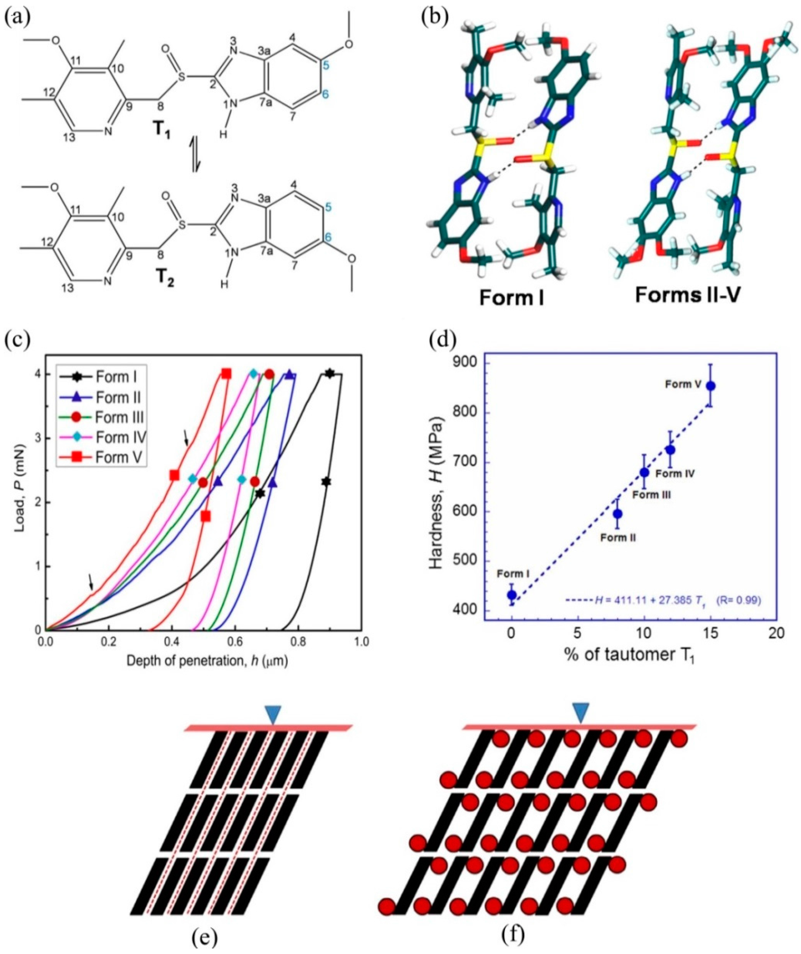
3.1.5. Tuning of Hardness in Organic Crystals

Mishra et al. [92] focused on methods to tune resistance to plastic flow (hardness) in organic crystals. In the case of ductile inorganic materials such as metals etc., numerous strengthening methods (such as grain boundary strengthening in polycrystalline samples, precipitation hardening in alloy materials, and work hardening–deformation at low temperatures) were developed and understood very well. However, the methods mentioned above do not work in the case of organic crystals. Mishra et al. [92] adopted an alternative method known as solid solution strengthening or hardening to tune the resistance to plastic flow in organic crystals. In the solid solution hardening method, the target hardness is achieved by mixing solute and solvent molecules in the desired concentration. Instrumented nanoindentation was employed on a series of omeprazole polymorphs (tautomeric forms of omeprazole are shown in Figure 12a,b), and revealed that proper design of the crystals using basic crystal engineering design principles leads to improving the lattice resistance to shear sliding of the molecular layers upon application of mechanical stress, thus increasing the organic crystals’ resistance to plastic flow [92]. A Berkovich tipped nanoindentation was performed on the major face {001} of five polymorphs of omeprazole. The characteristic P-h curves obtained from various polymorphs are shown in Figure 12c. The hardness values revealed that the hardness of polymorph V was nearly double that of polymorph I because of its layered structure and easy sliding nature during loading. However, despite having a similar layered structure in polymorphs II-V, they exhibited higher values of hardness because of the 5-methoxy group, which provides a higher resistance to shear sliding of molecular layers compared to polymorph I. The linear increase in hardness (see Figure 12d) in omeprazole polymorphic forms of I-V was attributed to the percentage of tautomer T1 in the polymorphs [92].

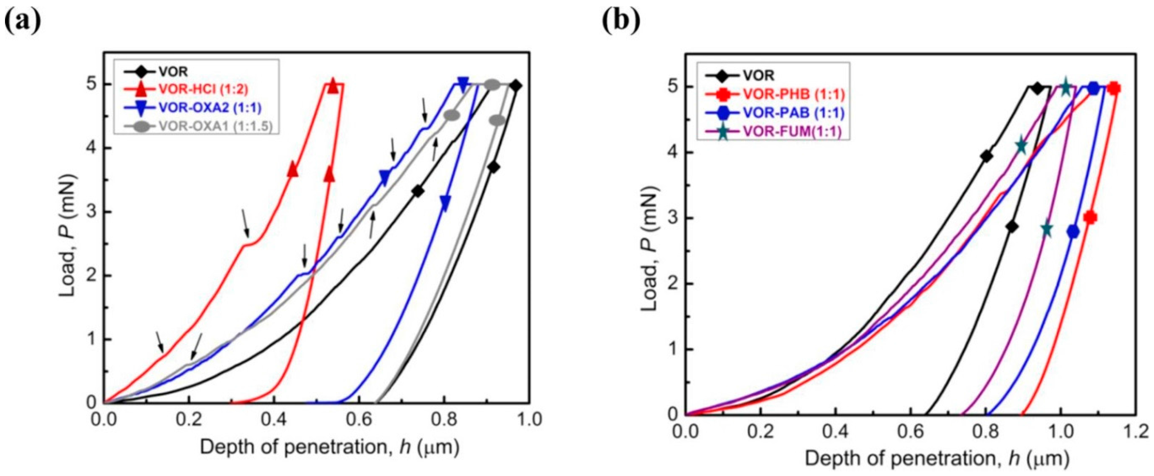
Strengthening Organic Crystals by the Co-Crystallization Approach

A three-sided pyramidal sharp nanoindentation was used by Sanphui et al. [93] to measure elastic and plastic properties and to understand the deformation behavior of voriconazole and its cocrystal and salt forms. The idea behind this study was to strengthen voriconazole, which is a highly soft material, by co-crystallizing voriconazole with both aliphatic and aromatic co-formers and forming salts with HCl and oxalic acid in different stoichiometric ratios. In fact, this method is known as the co-crystallization approach, known to alter the physicochemical and mechanical properties of Active Pharmaceutical Ingredients (APIs). [94,95]. It is evident from the literature that the mechanical properties and physiochemical properties were improved by forming cocrystals of caffeine with methyl gallate [96] ibuprofen, as well as flurbiprofenwith nicotinamide [97] and vanillin isomers with 6-chloro-2,4-dinitroaniline [98], etc. Similarly, Sanphui et al. [95] observed that the salt forms (i.e., voriconazole + HCl) were considerably stiffer (80%) and harder (58%) than voriconazole and its cocrystals. Further, the loading portions of the load-displacement curves obtained in the salt form showed pop-ins (Figure 13), indicating discontinuous plastic deformation, and their magnitude was the integer multiples of the interplanar spacing of the specific planes indented in the study. The lower hardness in voriconazole was attributed to the presence of weakly connected parallel slip planes in the indentation direction, which facilitated easy shearing or gliding for the planes during the application of mechanical pressure. However, the salt form resulted in increased hardness and stiffness because of the presence of the strong ionic interactions and hydrogen bonds in between the slip planes, which offer high resistance to the shearing of planes. Interestingly, the cocrystals exhibited in lower stiffness compared to the salt forms because of the presence of weaker non-covalent interactions in cocrystals, while salts have stronger ionic interactions.

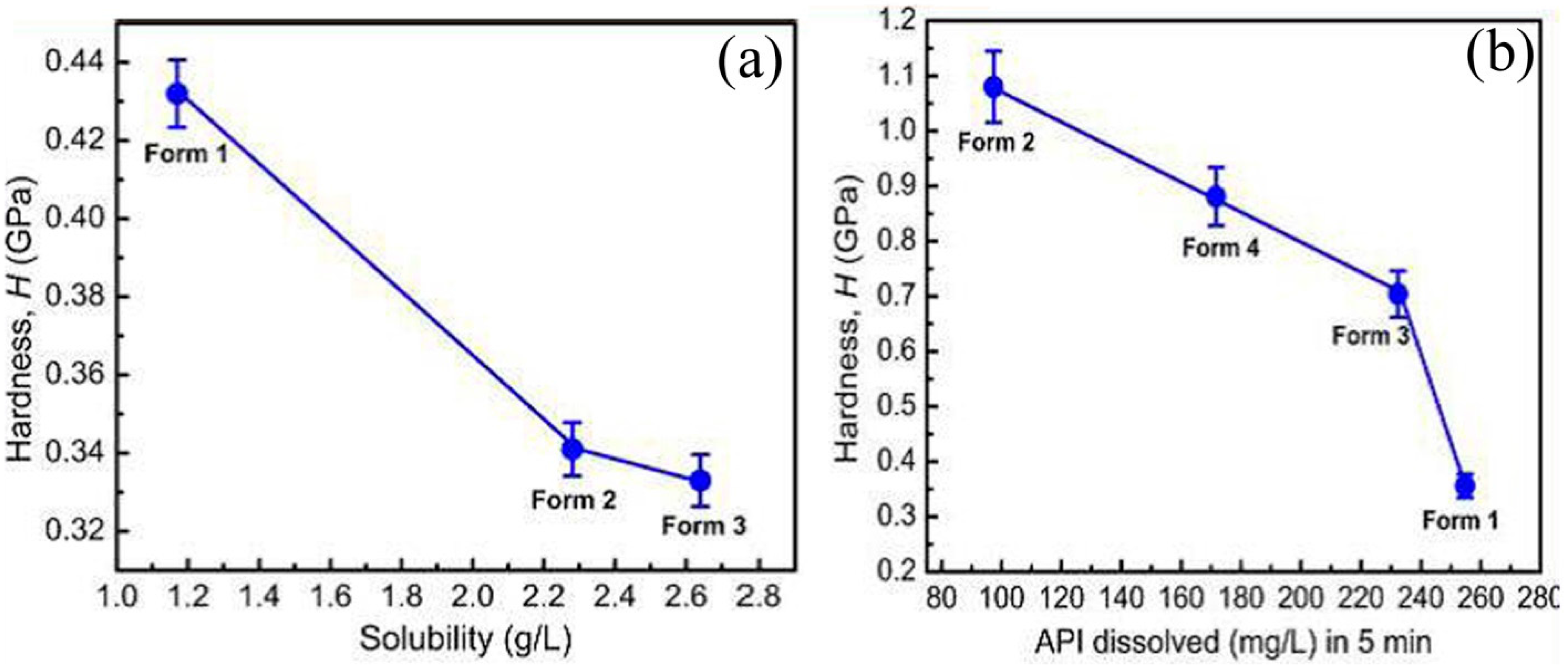
3.1.6. Establishing a Correlation Between Hardness and Solubility

Mishra et al. [99] investigated the correlation between the hardness and solubility of molecular crystals by performing nanoindentation on curcumin and sulfathiazole polymorphs. Among four sulfathiazole polymorphs, it was observed that polymorph I had the highest tendency to flow plastically upon mechanical pressure, and polymorph II was found to be the hardest because of the molecular layers that made a higher inclination angle with the indenter direction with respect to the different intermolecular interactions in I. In the case of curcumin, polymorph I was found to be the hardest because of the twisted molecular conformation in the crystal structure in comparison to polymorphs II and III, in which the closed cell parameters and planar structural packing allowed the polymorphs to deform plastically to a greater extent. The studies concluded that the hardness and solubility were inversely correlated in these polymorphs, as shown in Figure 14, indicating that the hardest polymorphs were less soluble and the softest were highly soluble. Further, the inverse relation suggested that the order of hardness can be utilized as a parameter to measure the solubility order in close energy-related polymorphic systems [99].
The Schmid factor values of the major faces of sulfathiazole polymorphs are summarized in Table 2 given below. The values of Schmid factor follow an inverse relation with the hardness of the crystal planes. Further, the molecular layers in forms II, III, and IV are normal to the indentation direction; therefore, pop-ins were noted in their P-h curves [99].
It is clear from the above table that the Schmid factor of form I is higher than that of forms II, III, and IV, and the inclination angle for form I is larger than that of the other forms; therefore, severe plasticity is seen in form I [99].

3.1.7. Indentation-Induced Plasticity in Parabens and Paracetamol

Feng and Grant [100] examined how the slip planes in parabens (such as methyl, ethyl, n-propyl, and n-butyl 4-hydroxybenzoate) influence the plastic behavior upon the application of mechanical stress. Instrumented nanoindentation was performed on the major faces of single crystal parabens of different morphologies (plate, blade, octahedral, etc.). The (111) face of methyl paraben exhibited the highest values of hardness among all the other parabens due to the absence of the slip planes. In the case of the ethyl (100) face, propyl (100) face, and butyl (002) face parabens, the slip planes facilitated severe plastic deformation upon the application of mechanical stress, which thus resulted in lower H values. Further, the highest d-spacing between the slip planes in the ethyl paraben caused increased slip activity compared to the isostructural propyl paraben; therefore, lower hardness values were observed. However, in the case of the butyl paraben, longer and more bulky alkyl chains provide resistance to the gliding of the slip planes; therefore, higher hardness compared to the ethyl and propyl parabens were observed. Duncan-Hewitt et al. [101] and Finnie et al. [102] performed indentation studies on paracetamol (acetaminophen) and revealed that the hardness varied as a function of indenter orientation with the crystallographic direction within the indentation planes.

3.1.8. Establishing the Relation between Plastic Behavior in Bulk and Single Crystals of APIs

Egart et al. [103] studied the nanomechanical properties of APIs such as nifedipine, famotidine, olanzapine, and piroxicam, in order to establish the plastic behavior correlation between bulk and single crystals. A distinct difference in the plastic behavior was observed in two polymorphs of famotidine due to the intermolecular packing under the indenter. While form I had the dense and highly cross-linked packing of molecules, form II had the slip planes that caused higher plasticity than form I. It is worth noting that lower hardness was measured for form II; though the indentation direction was normal to the slip plane and improved hardness was observed, it was still lower than that of form I. For the highly cross-linked structures, brittle behavior was observed. The authors established good correlations between bulk (Walker coefficient) and single crystal plasticity (indentation hardness) parameters. Their studies concluded that the inherent crystal deformation behavior based on the crystal packing greatly defined their compressibility and compactibility properties during tableting.

3.1.9. In Situ Nanoindentation to Study Disorders in APIs

Chen et al. [104] utilized nanoindentation along with high-resolution total scattering pair distribution function (TS-PDF) analysis coupled for mechanical property assessment and for the study of the disorders that can occur in API crystals during milling and tableting processes. While the PARP (poly (ADP-ribose) polymerase) compound was brittle in nature, sphingosine-1-phosphate receptor agonist and antagonist were plastic. The compound PARP exhibited almost four times higher hardness than the other compound. Significant fracture was evident on PARP, along with pop-ins in the loading portion of the P-h curve. However, the other compound exhibited pile-up, indicating severe plastic flow towards the surface along the sides of the indenter. The mechanical properties were attributed to the crystal packing in both compounds. After evaluating the mechanical properties of both compounds using nanoindentation, the crystals were milled and compacted under a variety of conditions. The resulting structural disorders during milling and compaction were then evaluated using synchrotron-based high-resolution total scattering pair distribution function (TS-PDF) analysis, and a good correlation was observed with the process conditions.

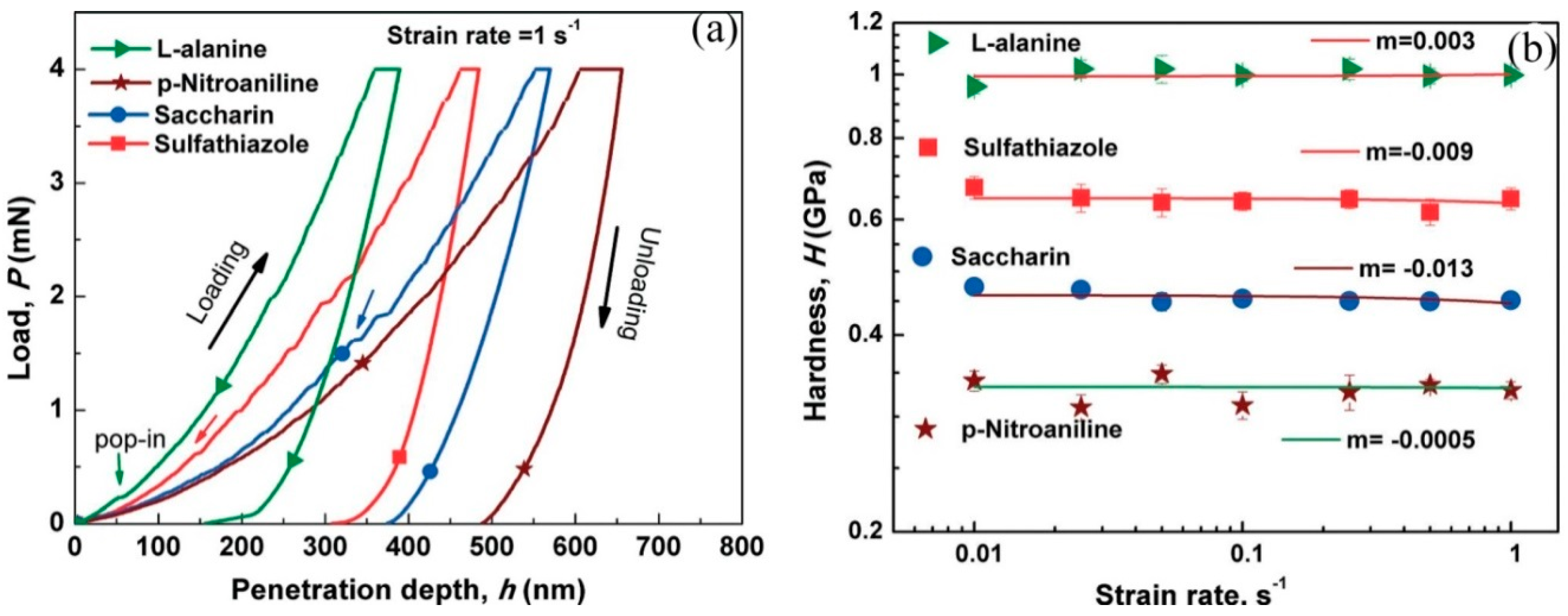
3.1.10. Strain-Rate Sensitivity Studies

Indentation strain-rate sensitivity (SRS) was examined for various organic crystals using the nanoindentation technique with a quasi-static load by Raut et al. [105]. They revealed that the plastic deformability does not depend on the rate at which the crystals are deformed. In the case of metals and alloys at room temperature, SRS is known to arise due to the lattice friction experienced by the dislocations during their glide over slip planes in response to the applied indentation stress [105]. The value of the strain-rate sensitivity index, m, ranges between 0 and 0.3 and increases with temperature, which is positive and high for metals, indicating higher resistance to the localization of plastic deformation [105]. However, the molecular crystals, which are stabilized by intermolecular interactions such as van der Waals (0.004–0.04 eV) and hydrogen bonds (0.1–0.4 eV), are considerably lower than metallic bonds (~1 eV). Therefore, the bonds break easily in organic crystals upon the application of pressure, which in turn implies that the plastic deformation does not require the movement of dislocations; slip can occur through shearing of slip planes [105]. Therefore, the m values for the organic crystals were measured close to zero and confirmed strain-rate insensitivity nature, as shown in Figure 15. Katz et al. [106] estimated the SRS using time-dependent plasticity studies via indentation creep tests on various APIs in the tablet form, and observed that the m values varied between 0.007 and 0.055, indicating that APIs are strain-rate insensitive. Though the above studies provide information regarding the role of SRS on the plastic behavior of organic crystals, they do not comment on the role of SRS in the pop-in behavior and fracture in organic crystals, which is necessary for a complete understanding of the SRS of organic crystals.

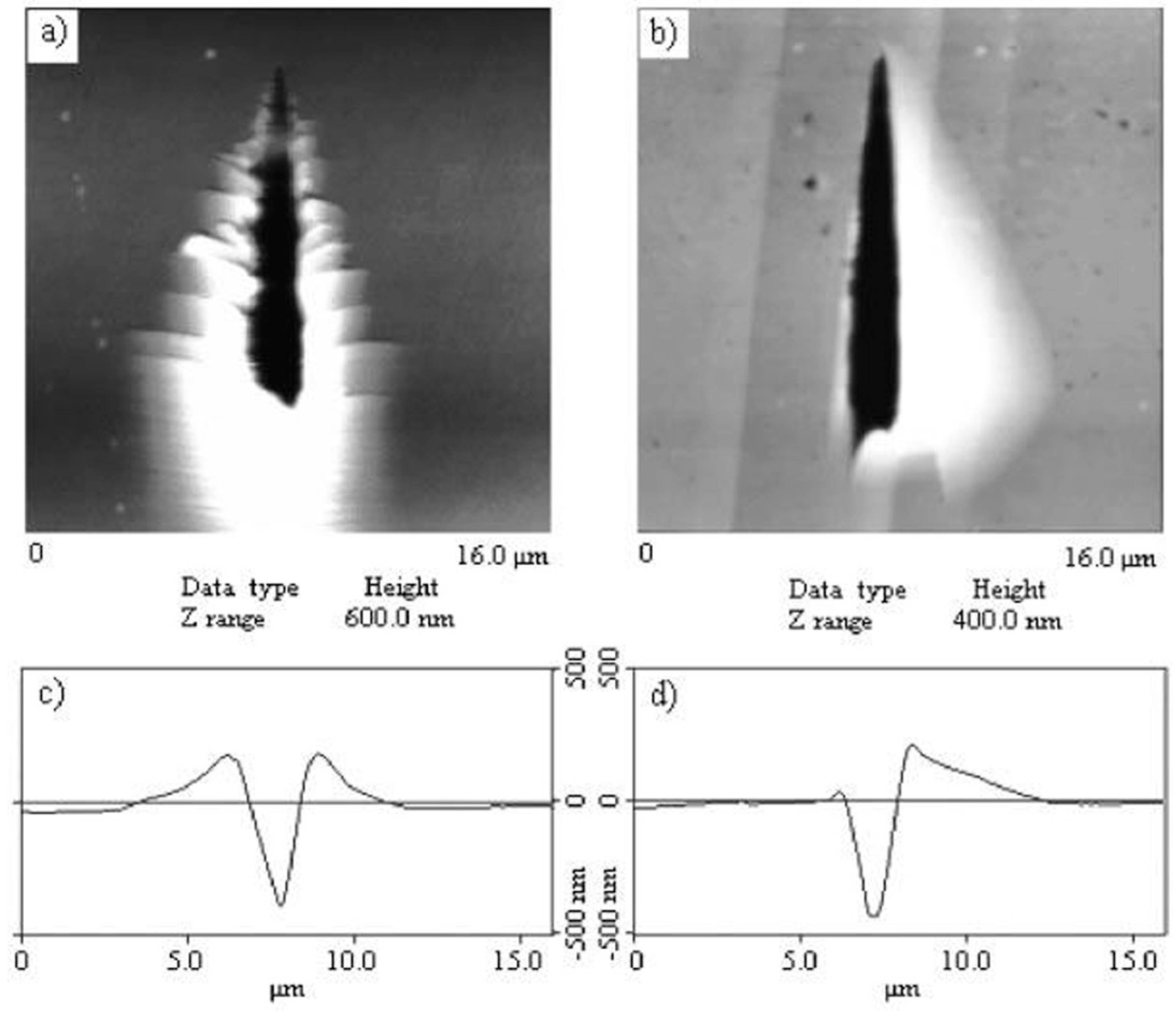
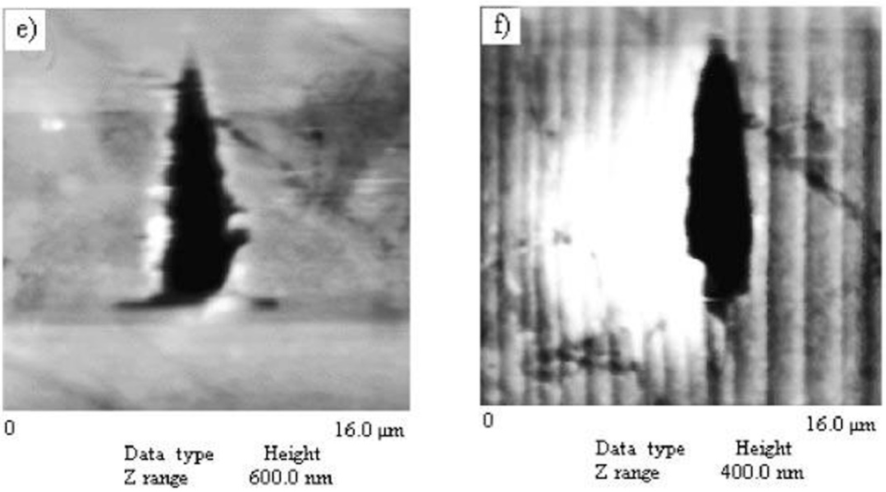
3.1.11. Nanoscratch Experiments: Anisotropy in Molecular Movements

Kaupp and Naimi-Jamal [107] reported the anisotropic deformation upon mechanical stress in organic crystals. They used nanoindentation and scratch experiments to demonstrate long-range anisotropic molecular movements in an organic crystal, as shown in Figure 16. Thiohydantoin crystal, which has a well-defined layered crystal with cleavage planes along the (102) planes, was indented with a cube corner tip on the (110) face. Interestingly, pile-up was observed only one side of the indenter (though it was a three-sided pyramidal tip), where the slope of the molecular monolayers matched with the indenter surface angle [107]. When nanoscratches were made at four different directions on the (110) face, four distinct molecular migration phenomena were seen (i.e., movement of molecular monolayers only to the left, only to the right, on both sides along with a pile-up in the scratch front, and the abrasion of the material) [107]. The molecular layers that were arranged in a 66° steep angle on the (110) face were greatly influenced. However, nanoscratching on the (102) cleavage plane resulted in no long-range molecular movement, but abrasion of the material was evident [107]. Further, anisotropic long-range molecular migration was detected in other compounds such as anthracene, ninhydrin, tetraphenylethylene, thiohydantoin, and thiourea, which have cleavage planes or anisotropic molecular packing, and such an effect was found to be dependent on the layer orientation arrangement and the direction of the tip movement [1].
Varughese et al. [108] studied the layer migration in pyrene and phenanthrene based on two charge transfer complexes of 1,2,4,5-tetracyanobenzene (TCNB) using nanoscratching experiments. A 75-nm sharp three-sided pyramidal Berkovich tip was used to scratch the major (100) and (002) faces of 1:1 TCNB–pyrene crystals, which have a layered arrangement (shown in Figure 17). While the layers mean that the plane is parallel to the (100), they make an angle of 68° tilt to (002). The large difference in the interaction characteristics and layer arrangement of both the faces resulted in significant mechanical anisotropy (H (16%) and E (21%)). Indentation on the (002) face resulted in two important plastic flow methods. They are: (1) the sliding of layers over the edge of the indenter tip and, (2) pile-up along one of the faces of the indenter. The sliding of the layers is attributed to the matching of the half angle of the indenter [108] to the molecular layers on the (002), which enables the layers to slide over the edge of the tip and creates pile-up in other orientations because of the slant arrangement of the layers [1]. The indentation scratch profile analysis and friction coefficient measurements on the (002) face revealed that the molecular migration was depndent on layer orientation and direction. As expected, the scratch along the tilt direction resulted in molecular layer migration, and such activity was noticeable on both sides of the scratch along with a small pile-up at the end of the scratch. Nevertheless, similar scratching against the tilted layered direction resulted in greater friction to the indenter movement and a significant pile-up at the end of the tip (see Figure 17 c,d). Unlike the TCNB–pyrene complex, the 1:1 TCNB–phenanthrene complex had no layer arrangement; the trimers stack down the [001], and they are approximately parallel to the (001) and perpendicular to the (020). Due to the entirely different molecular arrangements in this compound, nanoscratch experiments yield entirely different results compared to the TCNB-pyrene complex. When a scratch test was performed along the cleavage plane, limited layer migration was evident, as shown in Figure 18, which was attributed to the presence of hydrogen bonds in the interlayer region, providing high resistance to the indenter movement. Several unexpected observations were observed, such as the relation between the distance between two consecutive troughs to the multiples of interplanar spacing when scratched along the orthogonal direction.

3.1.12. AFM Nanoindentation to Study the Slip Planes

Jing et al. [109] studied the slip planes of succinic acid with a rotating sample method using AFM nanoindentation. An inhomogeneous stress field was created on the crystals using a sharp cube corner tip, which helped in activating different slip systems when the specimen was rotated. When indentation was performed on both the (001) and (010) crystal faces, the major slip planes were (010) and (111), and they were in agreement with the attachment energy calculations [109]. Interestingly, along with the predicted slip systems, several unpredicted higher index operative slips planes were also observed at different sample rotations [109]. The AFM images of residual indents on the (001) face of succinic acid, with the (010) trace being the reference, are shown in Figure 19.
Thakuria et al. [110] explored both the AFM and nanoindentation techniques to identify the two polymorphs of caffeine-glutaric acid cocrystals. They distinguished the variation in slip mechanism and height differences in supramolecular layers by AFM imaging and employing nanoindentation. Nanoindentation on both forms revealed that the resistance to plasticity of form I was lower than that of form II, which was attributed to the corrugation between the caffeine-glutaric acid layers that provide resistance to slide/stretch along the slip planes. The brittleness index showed that form II had a higher value than form I because of the higher ductile nature of form II. The indentation hardness data of a wide variety of organic crystals as well as their orientation dependence were measured by various groups, and are tabulated in Table 3.
Roberts and Rowe [111] proposed that the H/Py ratio can be used to assess the mechanical deformation of materials. Here Py indicates the yield pressure of the material. According to the H/Py ratio, the materials can be classified as, (i) very plastic for the ratio between 1.5–2.0, (ii) brittle for H/Py values in the range of 2.0–2.2, and (iii) plastic, if H/Py ≥ 3. However, Duncan-Hewitt et al. [112] proposed that a low H/E value yielded better compaction behavior of the APIs.

3.1.13. Real-Time Imaging of Indentation-Induced Structural Changes in Piroxicam

Manimunda et al. [113] coupled in situ SEM nanoindentation with Raman spectroscopy, with the intention of exploring the real-time indentation-induced structural deformation in the (011) and (011) faces of piroxicam single crystals, as shown in Figure 20. While the hardness of the (011) was 0.82 ± 0.03 GPa, the (011) face exhibited 0.64 ± 0.05 GPa. The mechanical anisotropy in both faces was attributed to the difference in the resolved shear stresses (RSS) and distinct difference in interlayer interactions along the [001] and [010] directions. In situ Raman spectroscopy at different loads on the (011) and (011) faces reveal changes in SO2 vibrational modes and C–O stretching modes during indentation, respectively, which was attributed to the variation in interlayer and intralayer interactions in both faces. These in situ studies provided real-time information on the chemical changes and corresponding mechanical deformation behavior of piroxicam crystals.

3.1.14. Phase Transformations under Applied Load

Lie et al. [114] investigated pressure-induced amorphization in acetaminophen, sucrose, c-indomethacin, and aspirin crystals under applied load. The plastic response was calculated using a phase field dislocation dynamics theory that could predict the fraction of amorphous material formed in crystals under an applied stress. Their results showed that the volume fractions of amorphous material after the plastic deformation were quite large for c-indomethacin and sucrose, and smaller for acetaminophen and aspirin. Though there are many studies on the phase transformation behavior of various organic crystals [115] under hydrostatic compression experiments (such as the diamond anvil cell test, where a tiny amount of powdered sample is placed between diamond anvils), to the best knowledge of the authors, there is no report so far seen on indentation-induced phase transformations in organic crystals.

4. Fracture Behavior of Organic Crystals

Since organic crystals are known as brittle materials, the accurate measurement of the fracture toughness becomes challenging, because creating a sharp pre-crack is quite difficult without breaking the specimen, and notched specimens give erroneously high values [123,124,125]. Therefore, an alternative approach was developed to assess the fracture toughness of brittle materials by making direct measurements of cracks created using sharp probes such as Vickers, Knoop, cube-corner, and Berkovich [126,127,128,129]. The sharp tips produce high strain under the tip that leads to a fracture. Therefore cube-corner and Berkovich tips with end radii of ~75 nm and ~30 nm, respectively, are usually used to investigate the fracture behavior of brittle materials at the nanoscale. A cube-corner tip results in better fracture because the total included angle is approximately 90°, compared to the Berkovich tip, which has a total included angle of 142.3°. Then, the critical stress intensity factor (KIC) is estimated using the crack length, indenting load, and the H/E ratio of the material. The fracture in molecular crystals takes place either through cleavage at certain crystallographic planes (brittle crystals) or at the maximum τ, where dislocation pile-up attains a critical density (ductile or plastic crystals) [1,90].
Lawn and colleagues [126,130] developed an expression for fracture toughness by relating the c, H, E, and Pmax, namely:
K I C = ξ ( E H ) 1 2 ( P max c 3 2 ) ,
The value of ξ, an empirical constant that depends on the geometry of the indenter, for the cube-corner indenter and the Berkovich indenter was 0.032 and 0.016, respectively, as proposed by Harding, Oliver, and Pharr [131]. Anstis et al. [127] showed the usefulness of this relation, by studying a number of brittle materials with a wide range of fracture toughness. It is important to note that the above expression is designed for ceramic materials, where the major assumption was that Kc depends on the assumption that P/c3/2 is constant. Taylor et al. [120] disclosed that the above assumption is also valid for pharmaceutical crystals. In their investigation, they observed that P/c3/2 is indeed constant for pharmaceutical materials. They used a much-refined form of the equation to find out fracture toughness for organic crystals, and it is given below [120]:
K c = x v ( a l ) 1 2 ( E H ) 2 3 ( P c 3 2 )
where xv is the calibration constant of the indenter used, a is the indent diagonal, l is the length of a crack, and c is the crack length given by a + l, as shown in Figure 21.
Lawn and Marshall [132] defined the brittleness of a material as the ratio of indentation hardness to fracture toughness. According to Lawn and Marshall [132], the brittleness index (BI) is:
B I = H K c
An excellent correlation was observed between the brittleness index and milling data for pharmaceutical crystals by Taylor et al. and Olusanmi et al. [90,120]. Based on the BI, APIs were distinguished and classified as easy, moderate, and difficult to mill. Hence, the BI can be used as a means of understanding the mechanical properties of compounds early in development, and for selecting appropriate milling conditions with a minimum amount of bulk [90,120].
Olusanmi et al. [90] observed that the activation energies of the various plastic deformation slip systems determine the intensity of the fracture. Earlier studies have shown that the fracture behavior in organic crystals is anisotropic. Elban et al. [83] reported that the freshly cleaved sucrose crystal surfaces of the (100) have a fracture toughness of 0.055 MPa.m1/2 at the load range of 0.15–4.9 N. However, at higher loads, the toughness value was reported to be lower by Duncan-Hewitt and Weatherly [133]. They could not observe the variation of fracture toughness for different planes, suggesting that the fracture behavior of sucrose was independent of the crystallographic direction, probably due to the isotropic nature of sucrose. Further, they observed short length cracks (compared to all other planes) on the (1 0 0) plane in the [1 1 0] direction. However, the preferred cleavage plane in sucrose is reported to be the (1 0 0), as well as the lowest attachment energy plane [134].
Duncan-Hewitt and Weatherly [134], in addition to microindentation studies by Prasad et al. [135], showed that the Kc of paracetamol was crystallographic orientation-dependent, with the lowest Kc measured on the (010) cleavage plane [90]. Also, they observed that most of the cracks formed parallel to the (010) plane when indented on different faces of paracetamol crystals. Olusanmi et al. [90] demonstrated strong fracture anisotropy in aspirin polymorph I, where cracks originated from plastically deformed regions and propagated on preferential cleavage planes. They observed that the Kc of the (001) plane was significantly lower than that of the (100), because the (001) plane is the preferred cleavage plane for aspirin polymorph I.
Varughese et al. [89] revealed interesting results on the fracture behavior of aspirin crystals. They also observed severe fracture on aspirin polymorph I on the (100), as also noted by Olusanmi et al. [90]. Since the radius of the plastic zone (rp) in front of the crack tip is inversely proportional to the square of the hardness (σ/3), it follows that the plane with higher Kc (higher rp) will have a lower value of hardness. Indeed, this was true in the Varughese et al. [89] case, because the (100) of form I holds the highest hardness among all other orientations and therefore severe fracture was observed. In addition, irrespective of indenter direction, fracture occurred along the <010> direction on the (100) of aspirin form I, as shown in Figure 22. The estimated Kc of the (100) of form I was 0.004 ± 0.0001 MPa m0.5, which was much lower than the (100) and (102) of form II, indicating the high fracture-resistant behavior of aspirin form I. The brittleness index of the (100) of aspirin form I was 49 × 103 m−0.5, which indicates that the aspirin form I crystals along the (100) were extremely brittle. Interestingly, no fracture was observed on the (001) of form I or on both faces of form II.
Kiran et al. [85] estimated the Kc of saccharin crystals to be 0.002 MPa m0.5. Wendy et al. [112] estimated the Kc of sucrose, adipic acid, and acetaminophen, as well as that of NaCl, using the microindentation technique, and reported the Kc values to be 0.08 ± 0.001, 0.02 ± 0.005, 0.05 ± 0.006, and 0.50 ± 0.07 MPa m0.5, respectively. The estimated brittleness index of saccharin was comparable to that of ice (2.8 × 10³ m−0.5) [85].
The Kc of the (−1 0 2) face of difluoroavobenzene (BF2AVB) mechanochromic crystals was estimated [91] using a Berkovich indenter to be 0.054 ± 0.002 MPa m0.5. The estimated BI of the BF2AVB crystals was 7.3 × 10³ m−0.5, which is much higher than that of ice (2.8 × 10³ m−0.5). Since the crystals are characterized by a three-dimensional arrangement of hydrogen bonds, no significant pile-up or fracture was seen along the (001) face. However, significant pile-up along the one side of the indent and several corners and radial cracks were observed for (120). The above results suggest that the anisotropic plastic deformation and fracture behavior in organic crystals arise as a consequence of molecular packing, and that interaction strengths are determined by the crystal structure.

5. Conclusions and Outlook

It is evident from the above literature that the mechanical behavior of organic molecular crystals has gained tremendous attention over the last 10 years with the advent of small-scale mechanical testing systems such as nanoindentation and computational methods. In particular, the instrumented nanoindentation technique under quasi-static (time-independent) loading conditions was effectively used on a wide variety of molecular crystals to gain knowledge on their anisotropic mechanical behavior and their structural origins. Compared to the molecular crystals, the structure-mechanical properties of other classes of materials like ceramics, metals, polymers, polymer nanocomposites, semiconductors, and Bulk Metallic Glasses (BMGs) are well explored by performing state-of-the-art experiments, computations, simulations, and theoretical methods. Although the mechanical behavior of molecular crystals is not yet completely realized, this area of research has significant potential for applications in polymer science, crystal engineering with desired properties, pharmaceutical technology, etc. For example, the better understanding of structure-mechanical property relationships saves the pharmaceutical industries from huge economic loss. H and Kc are two important mechanical properties that determine the compressibility and tabletability of APIs. Therefore, a wide selection of materials and the proper design of molecular solids with desired physiochemical properties using basic principles of crystal engineering are required to accomplish both millability and tabletability in APIs.
Plastic properties such as H, Kc, and m of different classes of materials were collected from the literature and are represented in Figure 23. It is clear from Figure 23a that the hardness values of organic molecular crystals vary between 200 MPa and 2 GPa. However, with the wise selection of materials and the modification of intermolecular interactions using the knowledge obtained from crystal engineering concepts, the ability to resist plastic deformation can be improved in this class of materials. As shown in Figure 23b, the fracture toughness of molecular crystals is the lowest among all the other classes of materials. It is important to have materials with higher hardness, but not by sacrificing another important property, namely, fracture toughness. Therefore, more research should be focused on achieving moderate hardness as well as fracture toughness. As shown in Figure 23c, the m value for organic crystals measures closer to zero or slightly towards a negative value, indicating the strain-rate insensitivity nature of molecular crystals under an applied load.
The present authors see great progress in understanding the relationship between structure-plasticity and structure-fracture of molecular crystals using the instrumented indentation technique. However, other than quite a number of indentation studies, the theoretical and computational understanding on the deformation behavior of organic crystals is lacking. Further, studies on the fatigue, creep, and temperature dependence of molecular crystals were not explored well. These studies are important as they provide information about the time-dependent plasticity, high strain-rate dependent plasticity, and the determination of activation volumes and energies at the elastic-plastic transition points. Further, the actual cause of plastic flow in organic crystals is also not yet clearly understood. For example, in the case of inorganic crystalline materials, plasticity was explained via dislocation activity [153,154], twinning [155,156], and phase transformations [153,156] under the indenter. However, such an understanding is lacking in regard to molecular crystals because performing post-indent chacracterizations such as cross-sectional Transmission Electron Microscopy (TEM) on molecular crystals is a challenging task.
Recent advances in techniques like picoindentation, powder compaction, and high-pressure-induced spectrometry have established [136] structure–mechanical property correlations in molecular crystals and have provided new insights on the subject. As small-scale mechanical testing equipment is now getting advanced in combination with other characterization techniques and imaging capabilities, in situ Raman, in situ electrical measurement, and in situ imaging capabilities provide excellent opportunities to explore and exploit pressure-induced phase transformations, real-time monitoring of indentation-induced plasticity and fracture mechanics during loading and unloading, and electrical conductivity measurements of conductive and piezoelectric organic crystals, etc.
The modulation of mechanical properties of a molecular solid by modifying intermolecular interactions has been achieved by some researchers [64,92,93]. Therefore, future aims should work towards engineering functional molecular solids with desired physical and chemical properties with the knowledge gained from the subject of crystal engineering and structure-mechanical property correlations.

Acknowledgments

Kiran S. R. N. Mangalampalli thanks the Science and Engineering Research Board, Department of Science and Technology, Government of India for an Early Career Researcher Award (File No: ECR/2016/000827).

Author Contributions

Kiran S. R. N. Mangalampalli wrote the manuscript. Sowjanya Mannepalli helped in collecting references and writing the manuscript.

Conflicts of Interest

The authors declare no conflict of interest.

References

  1. Varughese, S.; Kiran, M.S.R.N.; Ramamurty, U.; Desiraju, G.R. Nanoindentation in crystal engineering: Quantifying mechanical properties of molecular crystals. Angew. Chem. Int. Ed. 2013, 52, 2701–2712. [Google Scholar] [CrossRef] [PubMed]
  2. Egart, M.; Jankovi, B.; Lah, N.; Ilic, I.; Srcic, S. Nanomechanical properties of selected single pharmaceutical crystals as a predictor of their bulk behavior. Pharm. Res. 2015, 32, 469–481. [Google Scholar] [CrossRef] [PubMed]
  3. Loo, Y.L.; Someya, T.; Baldwin, K.W.; Bao, Z.; Ho, P.; Dodabalapur, A.; Katz, H.E.; Rogers, J.A. Soft, conformable electrical contacts for organic semiconductors: High-resolution plastic circuits by lamination. Proc. Natl. Acad. Sci. USA 2002, 99, 10252–10256. [Google Scholar] [CrossRef] [PubMed]
  4. Kim, W.; Palilis, L.C.; Uchida, M.; Kafafi, Z.H. Efficient silole-based organic light-emitting diodes using high conductivity polymer anodes. Chem. Mater. 2004, 16, 4681–4686. [Google Scholar] [CrossRef]
  5. Remenar, J.F.; Morissette, S.L.; Peterson, M.L.; Moulton, B.; Macphee, J.M.; Guzman, H.R.; Almarsson, O. Crystal engineering of novel cocrystals of a triazole drug with 1,4-dicarboxylic acids. J. Am. Chem. Soc. 2003, 125, 8456–8457. [Google Scholar] [CrossRef] [PubMed]
  6. Velaga, S.P.; Basavoju, S.; Bostrom, D. Norfloxacin saccharinate-saccharin dihydrate cocrystal—A new pharmaceutical cocrystal with an organic counter ion. J. Mol. Struct. 2008, 889, 150–153. [Google Scholar] [CrossRef]
  7. Kaiser, C.R.; Karlapais, C.; de Souza, M.V.N.; Wardell, J.L.; Solange, D.; Wardell, M.S.V.; Edward; Tiekink, R. Assessing the persistence of the n–h⋯n hydrogen bonding leading to supramolecular chains in molecules related to the anti-malarial drug, chloroquine. CrystEngComm 2009, 11, 1133–1140. [Google Scholar] [CrossRef]
  8. Schultheiss, N.; Newman, A. Pharmaceutical cocrystals and their physicochemical properties. Cryst. Growth. Des. 2009, 9, 2950–2967. [Google Scholar] [CrossRef] [PubMed]
  9. Sun, C.C. Materials science tetrahedron—A useful tool for pharmaceutical research and development. J. Pharm. Sci. 2009, 98, 1671–1687. [Google Scholar] [CrossRef] [PubMed]
  10. Byrn, S.R.; Pfeiffer, R.R.; Stowell, J.G. Solid-State Chemistry of Drugs; Ssci, Inc.: West Lafayette, IN, USA, 1999. [Google Scholar]
  11. Reddy, C.M.; Krishna, G.R.; Ghosh, S. Mechanical properties of molecular crystals—Applications to crystal engineering. CrystEngComm 2010, 12, 2296–2314. [Google Scholar] [CrossRef]
  12. Mørch, Y.A.; Holtan, S.; Donati, L.; Strand, B.L.; Bræk, G.S. Mechanical properties of c-5 epimerized alginates. Biomacromolecules 2008, 9, 2360–2368. [Google Scholar] [CrossRef] [PubMed]
  13. Rosa, C.D.; Auriemma, F. Structural-mechanical phase diagram of isotactic polypropylene. J. Am. Chem. Soc. 2006, 128, 11024–11025. [Google Scholar] [PubMed]
  14. Patel, S.; Sun, C.C. Macroindentation hardness measurement-modernization and applications. Int. J. Pharm. 2016, 506, 262–267. [Google Scholar] [CrossRef] [PubMed]
  15. Courtney, T.H. Mechanical Behaviour of Materials, 2nd ed.; Waveland Press Inc.: Long Grove, IL, USA, 2008. [Google Scholar]
  16. Rupert, T.J.; Gianola, D.S.; Gan, Y.; Hemker, K.J. Experimental observations of stress-driven grain boundary migration. Science 2009, 326, 1686–1690. [Google Scholar] [CrossRef] [PubMed]
  17. Tresca, H. Memoire Sur 1’ecoulement des Corps Solides Soumis a Des Fortes Pressions. C. R. Acad. Sci. Paris 1864, 59, 754–758. [Google Scholar]
  18. Saint-Venant, B.D. Memoire sur I’etablissement des Equations Differentielles des Mouvements Interieurs Operes Dans Les Corps Solides Ductiles au Dela des Limites ou I’elasticite Pourrait Les Ramener a Leur Premier etat. C. R. Acad. Sci. Paris 1870, 70, 473–480. [Google Scholar]
  19. Levy, M. Memoire Sur Les Equations Generales des Mouvements Interieurs des Corps Solides Ductiles au Dela Limits ou 1’Elasticite Pourrait Les Rammener a LeurPpremier etat. C. R. Acad. Sci. Paris 1870, 70, 1323–1325. [Google Scholar]
  20. Vonmises, R. Mechanics of solids and shells: Theories and approximations. Göttin. Nachr. Math. Phys. 1913, 1, 582–592. [Google Scholar]
  21. Lin, J. Fundamentals of Materials Modelling for Metals Processing Technologies: Theories and Applications; Imperial College Press: London, UK, 2015. [Google Scholar]
  22. Prager, W. Introduction to the Mechanics of Continua; Dover Publications Inc.: Mineola, NY, USA, 1961. [Google Scholar]
  23. Hill, R. The Mathematical Theory of Plasticity; Clarendon Press: Oxford, UK, 1950. [Google Scholar]
  24. Eduardo, A.; Neto, D.S.; Djordjeperic; David, R.; Owen, J. Computational Methods for Plasticity: Theory and Applications; Wiley Publishers: Hoboken, NY, USA, 2008. [Google Scholar]
  25. Sherwood, J.N. The Plastically Crystalline State (Orientationally-Disordered Crystals); Sherwood, J.N., Ed.; Wiley: Chichester, UK, 1979. [Google Scholar]
  26. Roberts, R.J.; Rowe, R.C.; York, P. The relationship between indentation hardness of organic solids and their molecular structure. J. Mater. Sci. 1994, 29, 2289–2296. [Google Scholar] [CrossRef]
  27. Ramamurty, U.; Jang, J. Nanoindentation for probing the mechanical behavior of molecular crystals—A review of the technique and how to use it. CrystEngComm 2014, 16, 12–23. [Google Scholar] [CrossRef]
  28. Brinell, J.A. Way of determining the hardness of bodies and some applications of the same. Tek. Tidskr. 1900, 5, 69–87. [Google Scholar]
  29. Meyer, E. Investigations of hardness testing and hardness. Phys. Z. 1908, 9, 66–74. [Google Scholar]
  30. Hutchings, I.M. The contributions of David Tabor to the science of indentation hardness. J. Mater. Res. 2009, 24, 581–589. [Google Scholar] [CrossRef]
  31. Tabor, D. A simple theory of static and dynamic hardness. Proc. R. Soc. Lond. A 1948, 192, 247–274. [Google Scholar] [CrossRef]
  32. Tabor, D. The Hardness of Metals; Oxford University Press: Oxford, UK, 1951. [Google Scholar]
  33. King, R.F.; Tabor, D. The effect of temperature on the mechanical properties and the friction of plastics. Proc. Phys. Soc. B 1953, 66, 728–736. [Google Scholar] [CrossRef]
  34. Pascoe, M.W.; Tabor, D. The friction and deformation of polymers. Proc. R. Soc. A 1956, 235, 210–224. [Google Scholar] [CrossRef]
  35. King, R.F.; Tabor, D. The strength properties and frictional behaviour of brittle solids. Proc. Phys. Soc. A 1954, 223, 225–238. [Google Scholar] [CrossRef]
  36. Atkins, A.G.; Tabor, D. Mutual indentation hardness of single-crystal magnesium oxide at high temperatures. J. Am. Ceram. Soc. 1967, 50, 195–198. [Google Scholar] [CrossRef]
  37. Liu, M. Crystal Plasticity and Experimental Studies of Nano-Indentation of Aluminium and Copper. Ph.D. Thesis, University of Wollongong, Wollongong, Australia, 2014. [Google Scholar]
  38. Fischer-Cripps, A.C. A review of analysis methods for sub-micron indentation testing. Vacuum 2000, 58, 569–585. [Google Scholar] [CrossRef]
  39. Oliver, W.C.; Pharr, G.M. An improved technique for determining hardness and elastic-modulus using load and displacement sensing indentation experiments. J. Mater. Res. 1992, 7, 1564–1583. [Google Scholar] [CrossRef]
  40. Oliver, P. Measurement of hardness and elastic modulus by instrumented indentation: Advances in understanding and refinements to methodology. J. Mater. Res. 2004, 19, 1–20. [Google Scholar] [CrossRef]
  41. Kucharski, S.; Mroz, Z. Identification of yield stress and plastic hardening parameters from a spherical indentation test. Int. J. Mech. Sci. 2007, 49, 1238–1250. [Google Scholar] [CrossRef]
  42. Kruzic, J.J.; Kim, D.K.; Koester, K.J.; Ritchie, R.O. Indentation techniques for evaluating the fracture toughness of biomaterials and hard tissues. J. Mech. Behav. Biomed. Mater. 2009, 2, 384–395. [Google Scholar] [CrossRef] [PubMed]
  43. Huber, N.; Tsakmakis, C. Experimental and theoretical investigation of the effect of kinematic hardening on spherical indentation. Mech. Mater. 1998, 27, 241–248. [Google Scholar] [CrossRef]
  44. Masri, R.; Durban, D. Cylindrical cavity expansion in compressible mises and tresca solids. Eur. J. Mech. A Solid. 2007, 26, 712–727. [Google Scholar] [CrossRef]
  45. Marsh, D.M. Plastic flow in glass. Proc. R. Soc. A 1964, 279, 420–435. [Google Scholar] [CrossRef]
  46. Rodriguez, J.; Rico, A.; Otero, E.; Rainforth, W.M. Indentation properties of plasma sprayed Al2O3-13% TiO2 nanocoatings. Acta Mater. 2009, 57, 3148–3156. [Google Scholar] [CrossRef]
  47. Johnson, K.L. Contact Mechanics; Cambridge University Press: Cambridge, UK, 1985. [Google Scholar]
  48. Page, T.F.; Oliver, W.C.; Mchargue, C.J. The deformation behavior of ceramic crystals subjected to very low load (nano) indentations. J. Mater. Res. 1992, 7, 450–473. [Google Scholar] [CrossRef]
  49. Bennet, D.W. Multi-Scale Indentation Hardness Testing: A Correlation and Model. Doctor’s Disertation, Oklahoma State University, Stillwater, OK, USA, 2008. [Google Scholar]
  50. Shibutani, Y.; Koyama, A. Surface roughness effect on the displacement bursts observed in nanoindentation. J. Mater. Res. 2004, 19, 183–188. [Google Scholar] [CrossRef]
  51. Agilent Technologies. Indentation Rules of Thumb-Applications and Limits; Agilent Technologies: Santa Clara, CA, USA, 2015. [Google Scholar]
  52. Qian, L.; Li, M.; Zhou, Z.; Yang, H.; Shi, X. Comparison of nanoindentation hardness to microhardness. Surf. Coat. Technol. 2005, 195, 264–271. [Google Scholar] [CrossRef]
  53. Kese, K.; Li, Z.C. Semi-Ellipse method for accounting for the pile-up contact area during nanoindentation with the berkovich indenter. Scr. Mater. 2006, 55, 699–702. [Google Scholar] [CrossRef]
  54. Choi, Y.; Lee, H.S.; Kwon, D. Analysis of sharp-tip-indentation load-depth curve for contact area determination taking into account pile-up and sink-in effects. J. Mater. Res. 2004, 19, 3307–3315. [Google Scholar] [CrossRef]
  55. Karthik, V.; Visweswaran, P.; Bhushan, A.; Pawaskar, D.N.; Kasiviswanathan, K.V.; Jayakumar, T.; Raj, B. Finite element analysis of spherical indentation to study pile-up/sink-in phenomena in steels and experimental validation. Int. J. Mech. Sci. 2012, 54, 74–83. [Google Scholar] [CrossRef]
  56. Zhou, X.; Jiang, Z.; Wang, H.; Yu, R. Investigation on methods for dealing with pile-up errors in evaluating the mechanical properties of thin metal films at sub-micron scale on hard substrates by nanoindentation technique. Mater. Sci. Eng. A. 2008, 488, 318–332. [Google Scholar] [CrossRef]
  57. Nix, W.D.; Gao, H. Indentation size effects in crystalline materials: A law for strain gradient plasticity. J. Mech. Phys. Sol. 1998, 46, 411–425. [Google Scholar] [CrossRef]
  58. Budiman, A.S. Indentation Size Effects in Single Crystal Cu as Revealed by Synchrotron X-ray Microdiffraction. In Probing Crystal Plasticity at the Nanoscales; Springer: Singapore, 2014; pp. 87–101. [Google Scholar]
  59. Reddy, C.M.; Gundakaram, R.C.; Basavoju, S.; Kirchner, M.T.; Padmanabhan, K.A.; Desiraju, G.R. Structural basis for bending of organic crystals. Chem. Commun. 2005, 31, 3945–3947. [Google Scholar] [CrossRef] [PubMed]
  60. Reddy, C.M.; Padmanabhan, K.A.; Desiraju, G.R. Structure-property correlations in bending and brittle organic crystals. Cryst. Growth Des. 2006, 6, 2720–2731. [Google Scholar] [CrossRef]
  61. Reddy, C.M.; Kirchner, M.T.; Gundakaram, R.C.; Desiraju, G.R. Isostructurality, Polymorphism and mechanical properties of some hexahalogenated benzenes: The nature of halogen—Halogen interactions. Chem. Eur. J. 2006, 12, 2222–2234. [Google Scholar] [CrossRef] [PubMed]
  62. Panda, M.K.; Ghosh, S.; Yasuda, N.; Moriwaki, T.; Mukharjee, G.D.; Reddy, C.M.; Naumov, P. Spatially resolved analysis of short-range structure perturbations in a plastically bent molecular crystal. Nat. Chem. 2015, 7, 65–72. [Google Scholar] [CrossRef] [PubMed]
  63. Thomas, S.P.; Shi, M.W.; Koutsantonis, G.A.; Jayatilaka, D.; Edwards, A.J.; Spackman, M.A. The elusive structural origin of plastic bending in dimethyl sulfone crystals with quasi-isotropic crystal packing. Angew. Chem. Int. Ed. 2017, 56, 8468–8472. [Google Scholar] [CrossRef] [PubMed]
  64. Saha, S.; Desiraju, G.R. Crystal engineering of hand-twisted helical crystals. J. Am. Chem. Soc. 2017, 139, 1975–1983. [Google Scholar] [CrossRef] [PubMed]
  65. Hagan, J.T.; Chaudhri, M.M. Fracture surface energies of high explosives PETN and RDX. J. Mater. Sci. 1977, 12, 1055–1058. [Google Scholar] [CrossRef]
  66. Halfpenny, P.J.; Roberts, K.J.; Sherwood, J.N. Dislocations in energetic materials. J. Mater. Sci. 1984, 19, 1629–1637. [Google Scholar] [CrossRef]
  67. Chaudhri, M.M. The junction growth equation and its application to explosive crystals. J. Mater. Sci. Lett. 1984, 3, 565–568. [Google Scholar] [CrossRef]
  68. Elban, W.L.; Hoffsommer, J.C.; Armstrong, R.W. X-ray orientation and hardness experiments on RDX crystals. J. Mater. Sci. 1984, 19, 552–566. [Google Scholar] [CrossRef]
  69. Elban, W.L.; Armstrong, R.W.; Yoo, K.C. X-ray reflection topographic study of growth defect and microindentation strain fields in an RDX explosive crystal. J. Mater. Sci. 1989, 24, 1273–1280. [Google Scholar] [CrossRef]
  70. Gallagher, H.G.; Miller, J.C.; Sheen, D.B.; Sherwood, J.N.; Vrcelj, R.M. Mechanical Properties of β-HMX. Chem. Cent. J. 2015, 9, 1–15. [Google Scholar] [CrossRef] [PubMed] [Green Version]
  71. Sun, C.C.; Kiang, Y.H. On the identification of slip planes in organic crystals based on attachment energy calculation. J. Pharm. Sci. 2008, 98, 3456–3461. [Google Scholar] [CrossRef] [PubMed]
  72. Ramos, K.J.; Hooks, D.E.; Bahr, D.F. Direct observation of plasticity and quantitative hardness measurements in single crystal cyclotrimethylene trinitramine by nanoindentation. Philos. Mag. 2009, 89, 2381–2402. [Google Scholar] [CrossRef]
  73. Ramos, K.J.; Bahr, D.F.; Hooks, D.E. Defect and surface asperity dependent yield during contact loading of an organic molecular single crystal. Philos. Mag. 2011, 91, 1276–1285. [Google Scholar] [CrossRef]
  74. Weingarten, N.S.; Sausa, R.C. Nanomechanics of RDX single crystals by force-displacement measurements and molecular dynamics simulations. J. Phys. Chem. A 2015, 119, 9338–9351. [Google Scholar] [CrossRef] [PubMed]
  75. Connick, W.; May, F.G.J. Dislocation etching of cyclotrimethylene trinitramine crystals. J. Cryst. Growth 1969, 5, 65–69. [Google Scholar] [CrossRef]
  76. Munday, L.B.; Solares, S.D.; Chung, P.W. Generalized stacking fault energy surfaces in the molecular crystal A-RDX. Philos. Mag. 2012, 92, 3036–3050. [Google Scholar] [CrossRef]
  77. Mathew, N.; Picu, R.C. Slip asymmetry in the molecular crystal cyclotrimethylenetrinitramine. Chem. Phys. Lett. 2013, 582, 78–81. [Google Scholar] [CrossRef]
  78. Taw, M.R.; Bahr, D.F. The mechanical properties of minimally processed RDX. propellants Explos. PyrTech. 2017, 42, 659–664. [Google Scholar] [CrossRef]
  79. Liu, J.; Zeng, Q.; Zhang, Y.; Zhang, C. Limited-Sample coarse-grained strategy and its applications to molecular crystals: Elastic property prediction and nanoindentation simulations of 1,3,5-trinitro-1,3,5-triazinane. J. Phys. Chem. C 2016, 120, 15198–15208. [Google Scholar] [CrossRef]
  80. Joshi, M.J.; Shah, B.S. On the microhardness of some molecular crystals. Cryst. Res. Technol. 1984, 19, 1107–1111. [Google Scholar] [CrossRef]
  81. Marwaha, R.K.; Sha, B.S. A study on the microhardness of organic molecular solids. Cryst. Res. Technol. 1991, 26, 491–494. [Google Scholar] [CrossRef]
  82. Sgualdino, G.; Vaccari, G.; Mantovani, G. Sucrose crystal hardness: A correlation with some parameters defining the growth kinetics. Cryst. Growth 1990, 140, 527–532. [Google Scholar] [CrossRef]
  83. Elban, W.; Sheen, D.; Sherwood, J.N. Vickers hardness testing of sucrose single-crystals. J. Cryst. Growth 1994, 137, 304–308. [Google Scholar] [CrossRef]
  84. Ramos, K.J.; Bahr, D.F. Mechanical behavior assessment of sucrose using Nanoindentation. J. Mater. Res. 2007, 22, 2037–2045. [Google Scholar] [CrossRef]
  85. Kiran, M.S.R.N.; Varughese, S.; Reddy, C.M.; Ramamurty, U.; Desiraju, G.R. Mechanical anisotropy in crystalline saccharin: Nanoindentation studies. Cryst. Growth Des. 2010, 10, 4650–4655. [Google Scholar] [CrossRef]
  86. Zhou, X.; Lu, Z.; Zhang, Q.; Chen, D.; Li, H.; Fudenie; Zhang, C. Mechanical anisotropy of the energetic crystal of 1,1-diamino-2,2-dinitroethylene (fox-7): A study by nanoindentation experiments and density functional theory calculations. J. Phys. Chem. C 2016, 120, 13434–13442. [Google Scholar] [CrossRef]
  87. Mathew, N.; Sewell, T.D. Nanoindentation of the triclinic molecular crystal 1,3,5-triamino-2,4,6-trinitrobenzene: A molecular dynamics study. J. Phys. Chem. C 2016, 120, 8266–8277. [Google Scholar] [CrossRef]
  88. Taw, M.R.; Yeager, J.D.; Hooks, D.E.; Carvajal, T.M.; Bahr, D.F. The mechanical properties of as-grown non-cubic organic molecular crystals assessed by nanoindentation. J. Mater. Res. 2017, 32, 2728–2737. [Google Scholar] [CrossRef]
  89. Varughese, S.; Kiran, M.S.R.N.; Solanko, K.A.; Bond, A.D.; Ramamurty, U.; Desiraju, G.R. Interaction anisotropy and shear instability of aspirin polymorphs established by nanoindentation. Chem. Sci. 2011, 2, 2236–2242. [Google Scholar] [CrossRef]
  90. Olusanmi, D.; Roberts, K.J.; Ghadiri, M.; Ding, Y. The breakage behaviour of aspirin under quasi-static indentation and single particle impact loading: Effect of crystallographic anisotropy. Int. J. Pharm. 2011, 411, 49–63. [Google Scholar] [CrossRef] [PubMed]
  91. Krishna, G.R.; Kiran, M.S.R.N.; Fraser, C.L.; Ramamurty, U.; Reddy, C.M. The relationship of solid state plasticity to mechanochromic luminescence in Difluoroboron avobenzone polymorphs. Adv. Funct. Mater. 2013, 23, 1422–1430. [Google Scholar] [CrossRef]
  92. Mishra, M.K.; Ramamurty, U.; Desiraju, G.R. Solid solution hardening of molecular crystals: Tautomeric polymorphs of omeprazole. J. Am. Chem. Soc. 2015, 137, 1794–1797. [Google Scholar] [CrossRef] [PubMed]
  93. Sanphui, P.; Mishra, M.K.; Ramamurty, U.; Desiraju, G.R. Tuning mechanical properties of pharmaceutical crystals with multicomponent crystals: Voriconazole as a case study. Mol. Pharm. 2015, 12, 889–897. [Google Scholar] [CrossRef] [PubMed]
  94. Smith, A.J.; Kavuru, P.; Wojtas, L.; Zaworotko, M.J.; Shytle, R.D. Cocrystals of quercetin with improved solubility and oral bioavailability of molecular crystals: Tautomeric polymorphs of omeprazole. Mol. Pharm. 2011, 8, 1867–1876. [Google Scholar] [CrossRef] [PubMed]
  95. Sanphui, P.; Tothadi, S.; Ganguly, S.; Desiraju, G.R. Salt and cocrystals of sildenafil with dicarboxylic acids Solubility and pharmacokinetic advantage of the glutarate salt. Mol. Pharm. 2013, 10, 4687–4697. [Google Scholar] [CrossRef] [PubMed]
  96. Sun, C.C.; Hou, H. Improving mechanical properties of caffeine and methyl gallate crystals by cocrystallization. Cryst. Growth Des. 2008, 8, 1575–1579. [Google Scholar] [CrossRef]
  97. Chow, S.F.; Chen, M.; Shi, L.; Chow, A.H.; Sun, C.C. Simultaneously improving the mechanical properties, dissolution performance, and hygroscopicity of ibuprofen and flurbiprofen by co-crystallization with nicotinamide. Pharm. Res. 2012, 29, 1854–1865. [Google Scholar] [CrossRef] [PubMed]
  98. Krishna, G.R.; Shi, L.; Bag, P.P.; Sun, C.C.; Reddy, C.M. Correlation among crystal structure, mechanical behavior, and tabletability in the co-crystals of vanillin isomers. Cryst. Growth Des. 2015, 15, 1827–1832. [Google Scholar] [CrossRef]
  99. Mishra, M.K.; Sanphui, P.; Ramamurty, U.; Desiraju, G.R. Solubility-Hardness correlation in molecular crystals: Curcumin and sulfathiazole polymorphs. Cryst. Growth Des. 2014, 14, 3054–3061. [Google Scholar] [CrossRef]
  100. Feng, Y.; Grant, D.J.W. Influence of crystal structure on the compaction properties of N-Alkyl 4-Hydrokxybenzoate Esters (Parabens). Pharm. Res. 2006, 23, 1608–1616. [Google Scholar] [CrossRef] [PubMed]
  101. Duncan-Hewitt, W.C.; Mount, D.L.; Yu, A. Hardness anisotropy of acetaminophen crystals. Pharm. Res. 1994, 11, 616–623. [Google Scholar] [CrossRef] [PubMed]
  102. Finnie, S.; Prasad, K.V.R.; Sheen, D.B.; Sherwood, J.N. Microhardness and dislocation identification studies on paracetamol single crystals. Pharm. Res. 2001, 18, 674–681. [Google Scholar] [CrossRef] [PubMed]
  103. Egart, M.; Ilić, I.; Janković, B.; Lah, N.; Srčič, S. Compaction properties of crystalline pharmaceutical ingredients according to the walker model and nanomechanical attributes. Int. J. Pharm. 2014, 472, 347–355. [Google Scholar] [CrossRef] [PubMed]
  104. Chen, S.; Sheikh, A.Y.; Ho, R. Pharmaceutical ingredient crystals using nanoindentation and high-resolution total scattering pair distribution function analysis. J. Pharm. Sci. 2014, 103, 3879–3890. [Google Scholar] [CrossRef] [PubMed]
  105. Raut, D.; Kiran, M.S.R.N.; Mishra, M.K.; Asiri, B.M.; Ramamurty, U. On the loading rate sensitivity of plastic deformation in molecular crystals. CrystEngComm 2016, 18, 3551–3555. [Google Scholar] [CrossRef]
  106. Katz, J.M.; Buckner, I.S. Characterization of strain rate sensitivity in pharmaceutical materials using indentation creep analysis. Int. J. Pharm. 2013, 442, 13–19. [Google Scholar] [CrossRef] [PubMed]
  107. Kaupp, G.; Naimi-Jamal, M.R. Mechanically induced molecular migrations in molecular crystals. CrystEngComm 2005, 7, 402–410. [Google Scholar] [CrossRef]
  108. Varughese, S.; Kiran, M.S.R.N.; Ramamurty, U.; Desiraju, G.R. Nanoindentation as a probe for mechanically-induced molecular migration in layered organic donar-acceptor complexes. Chem. Asian J. 2012, 7, 2118–2125. [Google Scholar] [CrossRef] [PubMed]
  109. Jing, Y.; Zhang, Y.; Blendell, J.; Koslowski, M.; Carvajal, M.T. Nanoindentation method to study slip planes in molecular crystals in a systematic manner. Cryst. Growth Des. 2011, 11, 5260–5267. [Google Scholar] [CrossRef]
  110. Thakuria, R.; Eddleston, M.D.; Chow, E.H.H.; Taylor, L.J.; Aldous, B.J.; Krzyzaniak, J.F.; Jonesa, W. Use of In-Situ atomic force microscopy to follow phase changes at crystal surfaces in real time. CrystEngComm 2013, 52, 10541–10544. [Google Scholar]
  111. Roberts, R.J.; Rowe, R.C. The compaction of pharmaceutical and other model materials: A pragmatic approach. Chem. Eng. Sci. 1987, 42, 903–911. [Google Scholar] [CrossRef]
  112. Duncan-Hewitt, W.C.; Weatherly, G.C. Evaluating the hardness, young’s modulus and fracture toughness of some pharmaceutical crystals using microindentation techniques. J. Mater. Sci. Lett. 1989, 8, 1350–1352. [Google Scholar] [CrossRef]
  113. Munimunda, P.; Hintsala, E.A.S.; Mishra, M.K. Mechanical anisotropy and pressure induced structural changes in piroxicam crystals probed by in-situ indentation and Raman spectroscopy. JOM 2017, 69, 57–64. [Google Scholar] [CrossRef]
  114. Lei, L.; Carvajal, T.; Koslowski, M. Defect-induced solid state amorphization of molecular crystals. J. Appl. Phys. 2012, 111, 073505. [Google Scholar] [CrossRef]
  115. Boldyreva, E.V.; Sowa, H.; Ahsbahs, H.; Goryainov, S.V.; Chernyshev, V.V.; Dmitriev, V.P.; Seryotkin, Y.V.; Kolesnik, E.N.; Shakhtshneider, T.P.; Ivashevskaya, S.N.; et al. Pressure-Induced phase transitions in organic molecular crystals: A combination of x-ray single-crystal and powder diffraction Raman and IR-spectroscopy. J. Phys. Conf. Ser. 2008, 121, 022023. [Google Scholar] [CrossRef]
  116. Mohamed, R.M.; Mishra, M.K.; Al-Harbi, L.M.; Al-Ghamdi, M.S.; Ramamurty, U. Anisotropy in the mechanical properties of organic crystals: Temperature dependence. RSC Adv. 2015, 5, 64156–64162. [Google Scholar] [CrossRef]
  117. Mishra, M.K.; Ramamurty, U.; Desiraju, G.R. Bimodal nanoindentation response of the (0 0 1) face in crystalline sodium saccharin dehydrate. Macedonian J. Chem. Chem. Eng. 2015, 34, 51–55. [Google Scholar] [CrossRef]
  118. Kiran, M.S.R.N.; Varughese, S.; Ramamurty, U.; Desiraju, G.R. Effect of dehydration on the mechanical properties of sodium saccharin dihydrate probed with nanoindentation. CrystEngComm 2012, 14, 2489–2493. [Google Scholar] [CrossRef]
  119. Egart, M.; Jankovi, B.; Srcic, S. Application of instrumented nanoindentation in preformulation studies of pharmaceutical active ingredients and excipients. Acta Pharm. 2016, 66, 303–330. [Google Scholar] [CrossRef] [PubMed]
  120. Taylor, L.J.; Papadopoulos, D.G.; Dunn, P.J.; Bentham, A.C.; Dawson, N.J.; Mitchell, J.C.; Snowden, M.J. Predictive milling of pharmaceutical materials using nanoindentation of single crystals. Org. Proc. Res. Dev. 2004, 8, 674–679. [Google Scholar] [CrossRef]
  121. Cao, X.; Morganti, M.; Hancock, B.C.; Masterson, V.M. Correlating particle hardness with powder compaction performance. J. Pharm. Sci. 2010, 99, 4307–4316. [Google Scholar] [CrossRef] [PubMed]
  122. Masterson, V.M.; Cao, X. Evaluating particle hardness of pharmaceutical solids using AFM nanoindentation. Int. J. Pharm. 2008, 362, 163–171. [Google Scholar] [CrossRef] [PubMed]
  123. Munz, D.; Bubsey, R.T.; Shannon, J.L., Jr. Fracture toughness determination of Al2O3 using four­point­bend specimens with straight­through and chevron notches. J. Am. Ceram. Soc. 1980, 63, 300–305. [Google Scholar] [CrossRef]
  124. Ritchie, R.O.; Dauskardt, R.H.; Yu, W.; Brendzel, A.M. Cyclic fatigue­crack propagation, stress­corrosion, and fracture­toughness behavior in pyrolytic carbon­coated graphite for prosthetic heart valve applications. J. Biomed. Mater. Res. 1990, 24, 89–206. [Google Scholar] [CrossRef] [PubMed]
  125. Fett, T.; Munz, D. Influence of narrow starter notches on the initial crack growth resistance curve of ceramics. Arch. Appl. Mech. 2006, 76, 667–679. [Google Scholar] [CrossRef]
  126. Lawn, B.R.; Evans, A.G.; Marshall, D.B. Elastic/Plastic indentation damage in ceramics: The median/radial crack system. J. Am. Ceram. Soc. 1980, 63, 574–581. [Google Scholar] [CrossRef]
  127. Anstis, G.R.; Chantikul, P.; Lawn, B.R.; Marshall, D.B. A critical evaluation of indentation techniques for measuring fracture toughness: I, direct crack measurements. J. Am. Ceram. Soc. 1981, 64, 533–538. [Google Scholar] [CrossRef]
  128. Fett, T.; Kounga, A.B.; Rodel, J. Stresses and stress intensity factor from cod of vickers indentation cracks. J. Mater. Sci. 2004, 39, 2219–2221. [Google Scholar] [CrossRef]
  129. Fett, T.; Njiwa, A.B.K.; Rodel, J. Crack opening displacements of vickers indentation cracks. Eng. Fract. Mech. 2005, 72, 647–659. [Google Scholar] [CrossRef]
  130. Lawn, B. Indentation fracture: Applications in the assessment of strength of ceramics. J. Aust. Ceram. Soc. 1980, 16, 4. [Google Scholar]
  131. Harding, D.S.; Oliver, W.C.; Pharr, G.M. Cracking during nanoindentation and its use in the measurement of fracture toughness. Mater. Res. Soc. Symp. Proc. 1995, 356, 663–668. [Google Scholar] [CrossRef]
  132. Lawn, B.R.; Marshall, D.B. Hardness, toughness, and brittleness: An indentation analysis. J. Am. Ceram. Soc. 1979, 62, 347–350. [Google Scholar] [CrossRef]
  133. Duncan-Hewitt, W.C.; Weatherly, G. Evaluating the fracture toughness of sucrose crystals using microindentation techniques. Pharm. Res. 1989, 6, 373–377. [Google Scholar] [CrossRef] [PubMed]
  134. Duncan-Hewitt, W.C.; Weatherly, G. Evaluating the deformation kinetics of sucrose crystals using microindentation techniques. Pharm. Res. 1989, 6, 1060–1066. [Google Scholar] [CrossRef] [PubMed]
  135. Prasad, K.V.R.; Sheen, D.B.; Sherwood, J.N. Fracture property studies of paracetamol single crystals using microindentation techniques. Pharm. Res. 2001, 18, 867–872. [Google Scholar] [CrossRef] [PubMed]
  136. Mishra, M.K.; Ramamurty, U.; Desiraju, G.R. Mechanical property design of molecular crystals. Curr. Opin. Solid State Mater. Sci. 2016, 20, 361–370. [Google Scholar] [CrossRef]
  137. Chung, Y.W.; Sproul, W.D. Super hard coating materials. MRS Bull. 2003, 28, 164–165. [Google Scholar] [CrossRef]
  138. Mishra, K.; Verma, D.; Bysakh, S.; Pathak, L.C. Hard and soft multilayered sicn nanocoatings with high hardness and toughness. J. Nanomater. 2013. [Google Scholar] [CrossRef]
  139. Berding, M.A.; Sher, A.; van Shilfgaarde, M.; Chen, A.B. Fracture and Hardness Characteristics of Semiconductor Alloys. Available online: http://www.dtic.mil/dtic/tr/fulltext/u2/a204807.pdf (accessed on 23 September 2017).
  140. Louzguine-Luzgin, D.V.; Louzguina-Luzgina, L.V.; Churyumov, A.Y. Mechanical properties and deformation behavior of bulk metallic glasses. Metals 2013, 3, 1–22. [Google Scholar] [CrossRef]
  141. Tan, J.C.; Cheetham, A.K. Mechanical properties of hybrid inorganic-organic framework materials: Establishing fundamental structure-property relationships. Chem. Soc. Rev. 2011, 40, 1059–1080. [Google Scholar] [CrossRef] [PubMed]
  142. Lee, J.; Novikov, N.V. Innovative Superhard Materials and Sustainable Coatings for Advanced Manufacturing. Available online: https://link.springer.com/book/10.1007/1-4020-3471-7?page=2 (accessed on 24 September 2017).
  143. Marinescu, I.D.; Tönshoff, H.K.; Inasaki, I. Handbook of Ceramic Grinding and Polishing; William Andrew Publishing: Norwich, NY, USA, 2000. [Google Scholar]
  144. Kutz, M. Handbook of Materials Selection; John Wiley and Sons: Hoboken, NJ, USA, 2002; pp. 384–424. [Google Scholar]
  145. Chen, C.P. Analytical Determination of Critical Crack Size in Solar Cells. Available online: https://ntrs.nasa.gov/archive/nasa/casi.ntrs.nasa.gov/19880017352.pdf (accessed on 23 September 2017).
  146. Chapter 3: Nanoindentation-Induced Mechanical Responses. Available online: https://ir.nctu.edu.tw/bitstream/11536/78079/5/180105.pdf (accessed on 23 September 2017).
  147. Xu, J.; Ramamurty, U.; Ma, E. The fracture toughness of Bulk metallic glasses. JOM 2010, 62, 10–18. [Google Scholar] [CrossRef]
  148. Subhash, G.; Koepper, B.J.; Chandra, A. Dynamic indentation hardness and rate sensitivity in metals. J. Eng. Mater. Technol. 1999, 121, 257–263. [Google Scholar] [CrossRef]
  149. Mason, J.K.; Lund, A.C.; Schuh, C.A. Determining the Activation Energy and Volume for the onset of Plasticity during Nanoindentation. Phys. Rev. B 2006, 73, 1–14. [Google Scholar] [CrossRef]
  150. Bhattacharyya, A.; Singh, G.; Prasad, K.E.; Narasimhan, R.; Ramamurty, U. On the strain rate sensitivity of plastic flow in metallic glasses mater. Sci. Eng. A 2015, 625, 245–251. [Google Scholar] [CrossRef]
  151. Golbe, D.L.; Wolff, E.G. Strain-rate sensitivity index of thermoplastics. J. Mater. Sci. 1993, 23, 5986–5994. [Google Scholar]
  152. Song, J.M.; Shen, Y.L.; Su, C.W.; Lai, Y.S.; Chiu, Y. Strain rate dependence on nanoindentation responses of interfacial intermetallic compounds in electronic solder joints with cu and ag substrates. Mater. Trans. 2009, 50, 1231–1234. [Google Scholar] [CrossRef]
  153. Bradby, J.E.; Williams, J.S.; Wong-Leung, J.; Swain, M.V.; Munroe, P. Transmission electron microscopy observation of deformation microstructure under spherical indentation in silicon. Appl. Phys. Lett. 2000, 77, 3749–3751. [Google Scholar] [CrossRef]
  154. Bradby, J.E.; Williams, J.S.; Wong-Leung, J.; Swain, M.V.; Munroe, P. Mechanical deformation of InP and GaAs by spherical indentation. Appl. Phys. Lett. 2001, 78, 3235–3237. [Google Scholar] [CrossRef]
  155. Bradby, J.E.; Williams, J.S.; Wong-Leung, J.; Swain, M.V.; Munroe, P. Nanoindentation-Induced deformation of Ge. Appl. Phys. Lett. 2002, 80, 2651–2653. [Google Scholar] [CrossRef]
  156. Kiran, M.S.R.N.; Tran, T.T.; Smillie, L.A.; Haberl, B.; Subianto, D.; Williams, J.S.; Bradby, J.E. Temperature-dependent mechanical deformation of silicon at the nanoscale: Phase transformation versus defect propagation. J. Appl. Phys. 2015, 117, 205901. [Google Scholar] [CrossRef]
Figure 1. Schematic diagram showing slip mechanism in a single crystal under compressive loading.
Crystals 07 00324 g001
Figure 2. Indentation hardness testing methods: Schematic of (a) the spherical indenter (Brinell and Meyer); (b) diamond pyramidal indenter (Vickers). (Adapted from Reference 30, reproduced with permission).
Crystals 07 00324 g002
Figure 3. Schematic diagram of the indentation load-displacement curve showing important measured parameters such as peak load, Pmax, maximum penetration depth, hmax, final depth after removing the load, hf, contact depth, hc, and the unloading stiffness, S. (Reproduced with permission from Materials Research Society, Reference 39).
Crystals 07 00324 g003
Figure 4. The plastic bending model of organic molecular crystals. (a) An undeformed crystal (half sectional view) where the weakest interactions represent white spaces between rows of stacks; (b) a bent crystal where the relative movement of the disk is highlighted in red, with pronounced deformation in interfacial angles (dashed line); and (c) the bending of C6Cl6 crystal. (Reproduced with permission from Royal Society of Chemistry, Reference 59).
Crystals 07 00324 g004
Figure 5. (a) As-grown crystal before performing the twist experiment. (b1b4) Twisting mechanism of the butter paper encapsulated crystal by hand. (c1c3) The hand-twisted helical crystal, as seen from different angles. The twisting at the middle is marked with red dotted lines. (Reproduced with permission from the American Chemical Society, Reference 64).
Crystals 07 00324 g005
Figure 6. (ae) Saccharin crystal with index faces, top view of intermolecular interactions in the (011) plane, oblique angle arrangement of molecules concerning the (100) plane, view of molecular arrangement along (001) plane, and the stacking of molecules in the [100] direction, respectively. The indentation direction (a*) is represented by the arrowhead. (f) Representative P-h curves obtained from the (100) and (011) planes. Arrows indicate pop-ins. (Reprinted with permission from the American Chemical Society, Reference 85).
Crystals 07 00324 g006
Figure 7. Molecular packing of FOX-7 crystals viewed along (top) and vertical to (bottom) the three indentation orientations of the (020) (a), (−101) (b), and (002) (c) faces, and (d) P−h curves obtained from (020), (-101), and (002) faces. The horizontal arrows represent pop-ins during loading. (Reproduced with permission from the American Chemical Society, Reference 86).
Crystals 07 00324 g007
Figure 8. (a) The representative P-h curves of TNT/CL-20, TATB, HMX, FOX-7, ADAAF. (b) The τ value at a yield normalized by Er shows that the window of plasticity is between 1 and 5% of the Er for multiple molecular crystals. (Reproduced with permission from Materials Research Society, Reference 88).
Crystals 07 00324 g008
Figure 9. Crystal packing of the aspirin polymorphic forms: (a) form I, and (b) form II. The planes parallel to the {001} or {102} are highlighted by grey slabs and slip planes are colored blue. (c) P-h curves obtained from different faces of both forms, with pop-ins indicated by arrows. (d) Post-indent image obtained from the {100} of form I shows a crack running along the <010> at higher loads. (Reproduced with permission from the Royal Society of Chemistry, Reference 89).
Crystals 07 00324 g009
Figure 10. The scanning electron microscopic image of residual indent impression on aspirin (a) (100) and (b) (001) faces. A fracture is evident in the [010] direction. (Reproduced with permission from Elsevier, Reference 90).
Crystals 07 00324 g010
Figure 11. Crystal packing of the BF2AVB, I (ac). Green form (brittle), II (ac). Cyan form, III. Representative P-h curves obtained from various faces ((011), (001), and (120)) of the green polymorph crystals and the (001) plane of the cyan polymorph. IV: The post-indent AFM image of the (120) face of the green polymorph shows cracks along the indenter corners. (Reproduced with permission from Wiley VCH, Reference 91).
Crystals 07 00324 g011
Figure 12. (a) Tautomeric forms of omeprazole. (b) All five forms of omeprazole contain centrosymmetric N-H···O=S dimers. Note the positioning of the 5- and 6-methoxy groups on the benzimidazole ring. (c) Representative P-h curves of all five forms of omeprazole. (d) The linear correlation between H and proportion of the 5-methoxy tautomer, T1 in omeprazole polymorphs. (e) Schematic crystal packing of omeprazole form I (a) and forms II–V (b). The dimers of are depicted as solid parallelograms. The direction of indentation [001] is shown as a solid triangle. Slip planes of the form I are represented by red dotted lines. (f) Note that the methoxy groups are shown in solid red circles in forms II–V. (Reproduced with permission from American Chemical Society, Reference 92).
Crystals 07 00324 g012
Figure 13. Representative P−h curves obtained on voriconazole and its (a) salts and (b) cocrystals. (Reproduced with permission from Elsevier, Reference 93).
Crystals 07 00324 g013
Figure 14. An inverse correlation of hardness and solubility in (a) curcumin and (b) sulfathiazole polymorphs. (Reproduced with permission from the American Chemical Society, Reference 99).
Crystals 07 00324 g014
Figure 15. (a) Representative P-h curves obtained using Berkovich nanoindentation on the major faces of different organic molecular single crystals at a strain rate of ε ˙ = 1 s−1, and (b) the m values obtained by fitting the indentation hardness data with the flowing equation, m = d l n H d l n ε ˙ . (Reproduced with permission from Royal Society of Chemistry, Reference 105).
Crystals 07 00324 g015
Figure 16. Atomic force microscope images of residual scratches on the (110) face of thiohydantoin crystal. (a) Along the skewed layers direction showing pile-up only on both sides, (b) scratch along the cleavage plane resulting in pile-up only on the right side, (c) horizontal cross-section profile at the broadest width in (a), (d) horizontal cross-section profile at the broadest width in (b), (e) scratch against the sloping of the skew layers showing no-pile up, and (f) scratch along the cleavage planes resulting in pile-up only on the left side. (Reproduced with permission from the Wiley, Reference 107).
Crystals 07 00324 g016aCrystals 07 00324 g016b
Figure 17. TCNB–pyrene complex. (a) Crystal packing. The major and minor faces are shown in red and green colored slabs. (b) Residual indent impression on the (002) showing pile-up only on one side of the indenter. (c) AFM scan image 25 µm in size, showing layer migration (towards the right direction only) upon nanoscratching. (d) Schematic representation of the indenter movement and layer arrangement. (Reproduced with permission from Wiley-VCH, Reference 108).
Crystals 07 00324 g017
Figure 18. TCNB–phenanthrene complex. (a) Crystal packing. (b) Schematic representation of the indenter movement along different directions and layer arrangement of the (020) face. (c) AFM image with a scan size of 25 µm, showing layer resistance towards the indenter movement and a limited pile-up at the end of the scratch track, and (d) The coefficient of friction at 0° and 90° shows distinct scratching behavior. The inset shows the inhomogeneous travel of the indenter during scratching against molecular layers. (Reproduced with permission from Wiley-VCH, Reference 108).
Crystals 07 00324 g018
Figure 19. AFM images of residual indents on the (001) face of succinic acid, with the (010) traces being the reference. (Reproduced with permission from American Chemical Society, Reference 109).
Crystals 07 00324 g019
Figure 20. (a,e) Crystal packing of piroxicam molecules along the (011) and (011) faces. (b,f) In situ SEM nanoindentation on the (011) and (011) faces along with P-h responses. (c,g) SEM images of the residual indent impressions on the (011) and (011) indented at 30 mN load, and (d,h) Raman spectra obtained from the (011) and (011) faces at different loads. (Reproduced with Permission from Springer and Copyright Clearance Center, Reference 113).
Crystals 07 00324 g020
Figure 21. Schematic diagram of a cube-corner indenter and the residual indent with surface cracks emanating from the indent corners. (Reproduced with permission from Elsevier, Reference 42).
Crystals 07 00324 g021
Figure 22. Irrespective of the indentation direction, the fracture is evident only in the <010> direction when indented on the {100} of aspirin polymorph I.
Crystals 07 00324 g022
Figure 23. Schematic representation of comparison of the (a) hardness [2,85,86,87,88,89,90,93,98,110,113,116,117,118,119,120,121,122,136,137,138,139,140]. (b) fracture toughness [85,89,90,110,112,141,142,143,144,145,146,147], and (c) strain-rate sensitivity [105,106,148,149,150,151,152] of organic crystals with other classes of materials.
Crystals 07 00324 g023
Table 1. Schmid factors of various slip systems for different planes of BF2AVB form I crystals [91].
Plane(011)(001)(120)
Indentation direction[016][001][810]
Slip plane(010)(010)(010)
Slip direction[001][001][100]
Schmid factor0.480.350.24
Hardness (Mpa)275 ± 12340 ± 7410 ± 11
2-D layers arranged (°) with respect to indentation plane229012
Table 2. The Schmid factor and plastic deformation behavior of sulfathiazole polymorphs [99].
Sulfathiazole PolymorphsMajor FaceSlip DirectionSchmid FactorH (GPa)Angle (Degree) between the Trace of the Molecular Layer and the Indentation Direction
Form 1(100)[102]0.4680.356 ± 0.010145.3
Form II(100)[102]0.0391.080 ± 0.01592.3
Form III(100)[001]0.0890.704 ± 0.01895.1
Form IV(10 1 ¯ )[001]0.0430.881 ± 0.01292.5
Table 3. The variety of organic crystals used by various research groups for nanoindentation study and their indentation hardness values.
S. NoCrystalCrystal FaceType of Tip UsedHardness, H (GPa)Reference
11,1-Diamino2,2-dinitroethylene(0 2 0)Berkovich0.52 ± 0.05[86]
(−1 0 1)-do-0.63 ± 0.02[86]
(0 0 2)-do-0.67 ± 0.03[86]
2Saccharin(1 0 0)Zircon Berkovich tip0.530 ± 3.0[116]
(0 1 1)-do-0.501 ± 2.3[116]
(1 0 0)A cube-corner indenter0.610 ± 0.01[85]
(0 1 1)A cube-corner indenter0.550 ± 0.02[85]
3L-alanine(0 0 1)-do-0.114 ± 4.8[116]
(1 0 1)-do-0.943 ± 3.1[116]
4BF2dbm(Bu)2(0 0 1)Berkovich0.092 ± 4.04[98]
5BF2dbm(OMe)2(0 1 0)Berkovich0.264 ± 10.8[98]
6BF2dbm(OMe)(0 0 1)Berkovich0.255 ± 8.48[98]
7Sodium Saccharin dihydrate crystals(0 0 1)Berkovich1.20 ± 0.04[117]
(0 0 1)-do-0.78 ± 0.03[116]
(0 1 1)-do-0.662 ± 0.02[118]
(1 0 1)-do-0.716 ± 0.02[118]
8Piroxicam form-1(−1 0 0)-do-0.56 ± 0.18[2,119]
(0 1 1)-do-0.67 ± 0.04[2,119]
(0 1 −1)-do-0.42 ± 0.02[2,119]
9Famotidine form A(−1 0 0)-do-1.58 ± 0.4[2,119]
(0 0 −1)-do-1.35 ± 0.16[2,119]
10Famotidine form B(−1 0 1)-do-0.84 ± 0.16[2,119]
11Nifedipineα-form(1 0 0)-do-0.71 ± 0.61[2,119]
12Olanzapine form 1(1 0 0)-do-0.74 ± 0.04[2,119]
(0 −1 −1)-do-0.72 ± 0.02[2,119]
13Aspirin polymorph-1(1 0 0)-do-0.257 ± 0.007[89]
(0 0 1 )-do-0.240 ± 0.008[89]
(0 0 1)-do-0.10[90]
(1 0 0)-do-0.12[90]
14Aspirin polymorph-2(1 0 2 ¯ )-do-0.152 ± 0.004[89]
15Sildenafil Citrate-----do-0.52 ± 0.06[120]
16Voriconazole-----do-0.13 ± 0.01[120]
17Sucrose(1 0 0)-do-1.62 ± 0.17[90]
(0 0 1)-do-1.57 ± 0.07[86]
-----do-2.3 ± 0..4[121]
----Diamond tip2 ± 0.5[122]
18Lactose----Diamond tip0.43 ± 0.08[122]
19Absorbic Acid----Diamond tip5.6 ± 1.8[122]
20TATB(0 0 1)Berkovich1.02 ± 0.09[87]
21α-RDX(2 1 0)-do-0.672 ± 0.035[87]
(2 1 0)-do-0.798 ± 0.030[87]
(2 1 0)-do-1.06[87]
(0 2 1)-do-0.681 ± 0.033[87]
(0 0 1)-do-0.615 ± 0.035[87]
(0 0 1)-do-1.05[87]
-----do-0.74 ± 0.09[88]
(0 2 1)-do-0.681[88]
(2 1 0)-do-0.798[88]
Multiple-do-0.74[88]
22β-HMX(0 1 0)-do-1.13 ± 0.045[87]
(0 1 0)-do-0.65 ± 0.09[87]
23HMX-----do-0.95[88]
(0 1 0)-do-0.65[88]
-do-0.99 ± 0.06[88]
24LIM-105(0 1 0)-do-0.72 ± 0.10[87]
25Acetaminophen(0 1 1)-do-0.875 ± 0.029[87]
26VOR(1 0 0)-do-0.366 ± 2.8[93]
27VOR-HCl(0 1 1 )-do-0.870 ± 6.0[93]
28VOR-OXA1(0 1 0)-do-0.426 ± 5.8[93]
29VOR-OXA2(1 0 0)-do-0.628 ± 2.0[93]
30VOR-FUM(1 0 0)-do-0.292 ± 3.4[93]
31VOR-PAB(1 0 0)-do-0.264 ± 5.0[93]
32VOR-PHB(1 0 0)-do-0.262 ± 1.6[93]
33Ibuprofen Lot A-----do-0.6 ± 0.1[121]
34Ibuprofen Lot B-----do-0.4 ± 0.1[121]
35Ibuprofen Lot C-----do-0.22 ± 0.04[121]
36UK-370106-----do-0.4 ± 0.1[121]
37Acetaminophen-----do-1.0 ± 0.2[121]
38Phenacetin-----do-0.9 ± 0.2[121]
39PHA-739521-----do-1.1 ± 0.1[121]
40MCC-----do-1.4 ± 0.3[121]
41Fluconazole-----do-2.0 ± 0.3[121]
42TATB(0 0 1)-do-0.48[88]
---- 0.41 ± 0.04
43TNT/CL-20---- 0.63 ± 0.13
44FOX-7(0 2 0) 0.52
( 1 ¯ 0 1) 0.63
(0 0 2) 0.67
---- 0.86 ± 0.08
46ADAAF---- 0.23
(2 1 0) 0.672
(0 0 1) 0.615

