Abstract
The coupled effects of the contact wire (CW) working surface profile and ambient humidity on the contact strip (CS) wear were investigated using a high-speed current-carrying friction and wear test rig. The experimental results revealed that the CW’s working surface profile determined the CS wear law of different friction pairs under high ambient humidity. Under low ambient humidity, when the current was less than or equal to 200 A, the ambient humidity determined the CS wear law; after the current exceeded 200 A, the change in the CW working surface profile became the decisive factor. Interestingly, when the current surpassed 300 A, the CW working surface profile significantly influenced the CS wear law.
1. Introduction
China possesses an extensive metro network. As of the end of 2024 [1], 58 cities in mainland China had put 12,168.77 km of urban rail transit lines into operation, of which the length of metro operating lines had reached 9281.37 km, accounting for 76.27%. There were seven cities in China with metro operating mileage exceeding 500 km. The Beijing Metro, with a total length of 806.09 km, has become the world’s longest operating metro line, with a maximum daily passenger volume of 12.5512 million. The busy metro transportation poses a huge challenge to the maintenance of the metro catenary. Since its introduction, the rigid catenary system has been widely used for over two decades. From the operation of the pantograph–catenary system (PCS), the contact state of the flexible catenary is good, while the rigid catenary relationship is poor [2]. According to the on-site data statistics of the metro [3,4,5,6,7,8], the wear rate of the contact strip (CS) in the rigid PCS ranges from 23 × 10−4 to 56 × 10−4 mm/km, and the contact wire (CW) also shows severe wear. Figure 1 and Figure 2 depict the normal and abnormal wear of the rigid PCS.
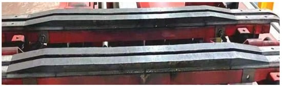
Figure 1.
Normal wear photo of the CS.
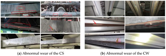
Figure 2.
Abnormal wear photo of the PCS.
In addition, on-site data shows that the abnormal wear of the metro rigid PCS has seasonal characteristics. Usually, the rigid PCS is prone to abnormal wear from mid-November at the end of each year to the end of February of the following year (considered as the winter months). However, the wear of the PCS almost returns to normal after entering March (the non-winter months). A certain metro line in China experienced a significant increase in CS wear after entering December 2022, resulting in the CS wear exceeding the limit. The abnormal wear of the CSs is shown in Figure 3. The wear rates of the three types of CSs used in this route before entering the winter months were 2.01 × 10⁻⁴ mm/km, 1.89 × 10⁻⁴ mm/km, and 1.95 × 10⁻⁴ mm/km, respectively. After entering December (winter month), the maximum wear rates of the three CSs reached 76.9 × 10⁻⁴ mm/km, 118.3 × 10⁻⁴ mm/km, and 52.7 × 10⁻⁴ mm/km, respectively.
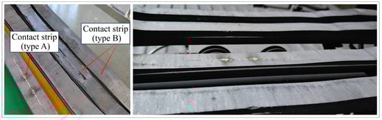
Figure 3.
CS abnormal wear to limit.
A similar wear phenomenon has also occurred in the PCS of the Urumqi Metro [9]. The wear rate of the PCS in winter is more than ten times higher than that in non-winter, and the carbon CS wear rate in winter is even dozens of times higher than that in non-winter, reaching its peak during the Spring Festival. According to statistics, during the 2022 Spring Festival period (low temperature, low humidity), the carbon CS wear rate reached 19.98 × 10⁻⁴ mm/km; During the Spring Festival period of 2024 (heating up and cooling down), the wear rate of carbon CSs reached 59 × 10−4 mm/km. In the Urumqi metro system, the temperature fluctuations in different seasons inside the tunnel are relatively small, while the ambient humidity changes are more significant. The ambient humidity inside the tunnel in summer is mainly distributed between 40% RH and 60% RH, while in winter it is between 12% RH and 20% RH. Statistics on the carbon CS wear show that when the ambient humidity of the environment is higher than 20% RH and the temperature is around 20 °C, the average wear rate of carbon CSs is less than 10 × 10−4 mm/km; When the ambient humidity is between 15% RH and 20% RH and the temperature is around 15 °C, the average wear rate of the carbon CS is distributed between 10 × 10−4 mm/km and 20 × 10−4 mm/km; When the ambient humidity continues to drop to 10% RH or lower, the average wear rate of carbon CSs exceeds 40 × 10−4 mm/km, and in late February 2024 (ambient humidity below 10% RH), the average wear rate of carbon CSs even approached 60 × 10−4 mm/km. So, the environmental humidity significantly influences the current-carrying friction and wear performance of the rigid PCS.
1.1. Effect of Ambient Humidity
Zhi et al. [10] studied the CS wear mechanism under different humidity conditions in the PCS. The study found that under the same experimental conditions, the CS wear rate under low humidity was much higher compared with high humidity. However, the friction coefficient (μ) under current-carrying conditions was lower. Li et al. [11] and Wang et al. [12] believed that environmental humidity significantly affected the friction and wear behavior of friction pairs. And there existed an optimal humidity value that was conducive to reducing the CS wear. Huang et al. [13] studied the PCS’s current-carrying friction and wear performance under ambient humidity conditions of 20% RH, 30% RH, and 40% RH using metal-impregnated CS commonly used in metro lines as materials. They pointed out that ambient humidity significantly impacted the CS wear process. The CS wear rate decreased with the increase in ambient humidity, and during the rise in ambient humidity, the CS mechanical wear weakened while the electrical wear increased. Wu et al. [14] studied the influence of relative humidity on the current-carrying frictional properties of Cu-C sliding contact pairs. They believed that when the ambient humidity rose from 0% RH to 80% RH, the μ showed an inverted U-shape, and the wear increased continuously with the increase in ambient humidity. Sun et al. [15] and Song et al. [16] investigated the current-carrying friction and wear performance of Cu/Cu rolling contact pairs under different environmental humidities. The results showed that the higher the environmental humidity, the greater the μ and contact resistance, and when the environmental humidity was the same, the μ under current-carrying conditions was higher. They believed that the participation of water vapor promoted the chemical oxidation, and as the environmental humidity increased, the wear mechanism of the friction pair material changed.
Hu et al. [17] studied the effect of ambient humidity on the wear rate of graphite carbon brushes. They pointed out that the wear rate of brushes under 10% RH was about twice that under 50% RH conditions. Ji et al. [18] studied the friction and wear properties of carbon/Cu pairs under different environmental humidities (10% RH to 80% RH) with and without current loading. The experimental results showed that under low current conditions, a competitive relationship existed between the CS’s abrasive wear and material transfer wear with increasing ambient humidity, and there was a decreasing trend. Ji et al. [19] studied the current-carrying friction and wear performance of carbon/copper friction pairs under ambient humidity of 10% RH and 80% RH, service temperatures of −20 °C, 0 °C, and 20 °C, and current flow of 5 A and 10 A. They pointed out that ambient humidity and temperature significantly impacted the μ. An increase in environmental humidity increased the average contact resistance and accumulated arc energy of the friction pair, and changed the wear mechanism of the material. In summary, there are differences in the wear patterns of CSs under different environmental humidities.
1.2. Effect of CW Profile and Research Gaps
Current experimental research on the influence of ambient humidity on the CS wear is predominantly confined to the standard CW/CS friction pairs. While Ren et al. [20] investigated the impact of CW profiles on CS wear, they did not account for ambient humidity. Moreover, studies examining the influence of material profile variations on the current-carrying friction and wear characteristics of PCS remain scarce. Given that the interaction between the PCS profile and varying ambient humidity levels is critical to the CS wear mechanism, this study aims to explore the coupling effects of these two factors on the current-carrying friction and wear performance of PCS, as well as on the underlying CS wear mechanism. Specifically, the objectives are: (1) to quantify the individual and coupled effects of CW profile and ambient humidity on CS wear; (2) to identify threshold conditions where dominant factors shift; (3) to elucidate wear mechanisms through microscopic analysis.
2. Experimental Details
2.1. Experimental Equipment and Materials
The tests were implemented using a ring-block current-carrying rig, with speeds ranging from 0 to 400 km/h, as shown in Figure 4a. Its normal force can adjust from 5 N to 300 N. The power supply used in this experiment can stably output currents within the range of 0–800 A. Figure 4b depicts the data acquisition system and the distribution positions of all sensors. The sampling frequency in these tests was set at 1000 Hz. To monitor the real-time temperature field of the pantograph strip/contact wire friction pair, a FLUKE TiX640 infrared thermal imager was aligned with the friction pair and positioned in proximity, ensuring no interference with the test operation to minimize measurement error. Its temperature measurement range is –40 to 1200 °C with an accuracy of ±1.5 °C. Besides, an environmental control box was installed around the test rig to regulate the ambient humidity. The ambient humidity was measured using a high-precision hygrometer with a range of 0–100% RH and an accuracy of ±3% RH. Accompanied by humidifiers and dehumidifiers, the experimental humidity was controlled at two set points, 20% RH and 50% RH, with fluctuations controlled within ±3% RH.
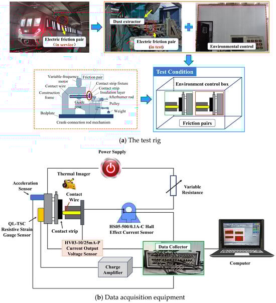
Figure 4.
Test equipment.
The materials used were a metal-impregnated carbon CS and an in-service copper-silver alloy CW. The chemical ingredients of the CS and the CW are shown in Table 1 and Table 2. This paper aimed to study the coupled effect of CW working surface profile and ambient humidity on the PCS’s current-carrying friction and wear performance. So, two kinds of CWs (i.e., the standard and the worn CWs) and ambient humidities (i.e., the low and high ambient humidities) were selected. The worn CW was processed by cutting and retained about 70% of the good surface. After processing, there was no need to polish the friction surface of the CW, but the friction surface needed to be wiped with alcohol to remove residual impurities on the surface before the test. The actual images and schematic diagrams of the CW and the CS sample are shown in Figure 5.

Table 1.
Chemical ingredients and the density of the CS (weight %).
Table 2.
Chemical ingredients and the property parameters of the copper–silver alloy CW (weight %) [20].
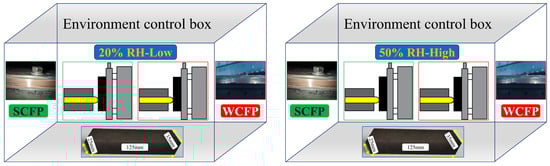
Figure 5.
Images and diagrams of the test samples.
2.2. Experimental Procedures and Parameters
The CSs before the test were cut to the size shown in Figure 5 and polished with 600-grit sandpaper to make their roughness meet the test requirements. After grinding, the initial mass of the CSs was obtained using an electronic scale with an accuracy of 0.1 mg. The CW was first processed into a standard CW, and the circular runout of the CW was less than 0.5 mm. Then, 1000-grit sandpapers were used to polish the friction surfaces to make their roughness meet the test requirements. Secondly, the worn CWs mentioned in Section 2.1 were processed based on standard CWs. Both kinds of test CWs’ surfaces were wiped with alcohol to remove the residues from the CW surface. Ambient humidity was divided into two humidities—low and high humidity. In a low-humidity environment, the ambient humidity in the prefabricated house was controlled at about 20% RH; In a high-humidity environment, the humidity was controlled at about 50% RH. Under two humidity conditions, the standard CW and worn CW were used to match the metal-impregnated carbon CS for the tests. The test parameters are shown in Table 3.
Table 3.
Test conditions [20].
After comprehensive preparations and pre-grinding, formal tests were conducted according to the design conditions. Three repeated tests were conducted under each working condition, and if an abnormal result occurred, an additional test was performed. The average of the three valid test results was taken as the test results under each condition.
2.3. Surface Morphology and Composition Analysis
After testing, the contact wires were cut to a length of 15 mm, and the contact strips were cut into dimensions of 15 × 15 × 15 mm3. Following the cutting process, the samples were cleaned with 95% concentration alcohol to remove any impurities adhering to the surface resulting from the machining.
The surface morphology of the CS wear scars was characterized using a scanning electron microscope (SEM) (Thermo Scientific Quattro ESEM), operated in high vacuum mode with an accelerating voltage of 10–15 kV and a working distance of approximately 10 mm.
The chemical composition and elemental distribution on the worn surface were analyzed by energy-dispersive X-ray spectroscopy (EDS) using an EDAX Octane Elect system attached to the SEM. Both point analysis and elemental mapping were performed at an accelerating voltage of 15 kV with a live time of 30–60 s. The acquired EDS spectra were quantified using the standardless ZAF correction routine within the EDAX TEAM™ software (version Loctane Elact) suite.
2.4. Calculation of the CS Wear and Test Parameters
CS wear is the most intuitive parameter to evaluate the degree of CS wear. The higher the wear volume, the worse the wear resistance of the CS. The CS was easy to disassemble in the tests, so the electronic scale was used to measure its quality. The CS wear was the average of three valid test results, and its calculation formula is as follows:
where is the CS wear volume; is the quality of the CS after grinding before testing; is the quality of the CS after testing; is the density of the CS; n is the number of valid test data.
An electric arc is a form of gas discharge. When the pantograph CS and CW are separated, arc combustion can ensure the continuous flow of the train, thus maintaining the operation of the train [21]. However, a large amount of heat energy will be generated during the arc burning process, which can cause arc ablation on the CS and CW surface and reduce the service life of the PCS. In addition, the high temperature generated by intermittent arc discharge leads to uneven heating of the CWs, decreasing the tensile strength of the CWs and increasing the risk of CW breakage. So, arc discharge is closely related to pantograph–catenary wear [22,23]. Therefore, analyzing the changing trend of arc discharge energy can provide important references for studying CS wear mechanisms. The arc discharge energy can be calculated as follows:
where E is the arc discharge energy (J/s), I is the electric current (A), and U is the arc voltage between the charged friction pairs.
Current-carrying efficiency is one of the reliable indicators to evaluate the current flow quality of the PCS, which is expressed as the ratio between the actual current passing through the friction interface and the rated loading current. It was calculated as follows [24]:
where is the current-carrying efficiency (%); is the effective passing current between the pantograph and catenary (A); is the nominal value of the test current (A).
The sliding current collection mode between the pantograph CS and the rigid catenary inevitably causes the PCS to go offline. The significant arc discharge caused by the offline ablates the friction surface of the materials, deteriorating the matching relationship between the pantograph and catenary. For example, the pantograph/catenary offline in Shanghai Metro Line 2 caused a 5-h suspension of this section, and the failure of this section also had a significant impact on trains in other sections because of the well-developed network of Shanghai Metro [25]. Offline arc discharge will ablate the CS and CW surfaces and cause current and voltage fluctuations, damaging the power supply equipment. In addition, arc discharge can produce a strong electromagnetic field, causing interference to onboard equipment, sensors, communication systems, and peripheral equipment, even endangering driving safety in extreme cases. Hence, studying the impact factors of the pantograph/catenary offline is significant to ensure the safe operation of metro trains. Accordingly, the offline rate can be calculated as follows:
where lx is the mean offline rate value, ti is the single arcing time, and T is the test time.
The friction coefficient (μ) is an important indicator reflecting the friction and wear characteristics of the sliding friction interface of the contact pairs. Some scholars believed [24,26] that the μ mainly comprises three parts: the ploughing part, the micro-convex deformation part and the adhesion part. During the sliding contact of the friction pair, the three parts fluctuate dynamically with the change in working conditions to reflect the wear situation of the contact surface in real time. Analyzing the μ changes under different working conditions is of great help in exploring the wear mechanism of the CWs and CSs. The average μ of the friction pair can be expressed as follows:
where μ is the average friction coefficient of the friction pair, is the dynamic friction force collected in real time, is the loaded normal force, and K is the total number of test samples.
Temperature rise is a critical parameter for understanding its influence on friction, wear, and arcing behavior. Its measurement was focused on position P1 (the contact point between the contact strip and the wire), which lies within the reciprocating motion zone delineated in Figure 6. Owing to substantial temperature fluctuations observed in the initial stage, data acquisition was initiated after the system stabilized. The final temperature values presented are averages of the data, calculated to reduce the influence of environmental fluctuations within the test space.
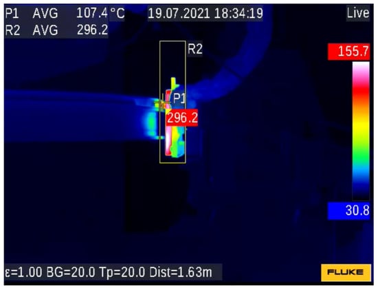
Figure 6.
Example of temperature measurement.
3. Test Results
3.1. Friction Coefficient—
Figure 7 shows the variation curves of μ under different test conditions. In Figure 7, with the increase in current, normal force, and sliding velocity, μ showed a downward trend. Among them, the μ of the standard contact wire/contact strip friction pair (SCFP) in high ambient humidity was the highest, and the μ of the worn contact wire/contact strip friction pair (WCFP) in low ambient humidity was the lowest. From Figure 7a, the μ of the friction pairs was significantly higher without current. Where the μ of the SCFP was the highest in lower ambient humidity, reaching 0.50, while the μ of the WCFP was only 0.28. In high ambient humidity, both of the μ were close to 0.50. As the current was loaded, the μ of both friction pairs showed a decreasing trend.
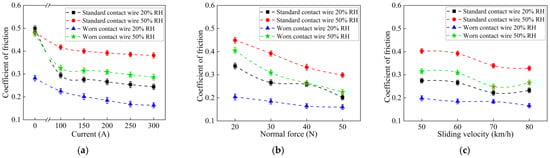
Figure 7.
Friction coefficients. (a) Relative to current (Fn = 30 N, v = 60 km/h). (b) Relative to normal force (I = 200 A, v = 60 km/h). (c) Relative to sliding velocity (Fn = 30 N, I = 200 A).
3.2. Wear Volume of the CS—
Figure 8 shows the variation in the CS wear volume (wv) with the test conditions, and the wv of the two friction pairs increased with the rise in current and sliding velocity and decrease in the normal force. For both friction pairs, the wv in low ambient humidity was significantly greater than in high ambient humidity. As seen in Figure 8a, the increase in current intensified the CS wear of the two friction pairs. However, there were differences between the two: with the current increase, the wv of the SCFP increased slowly, while the wv of the WCFP increased significantly. When the current increased from 200 A to 300 A, the wv of the SCFP increased by about 33.63% and 9.51%, respectively, in the high and low ambient humidity; the wv of the WCFP increased by about 66.67% and 101.45%, respectively, under the same conditions.
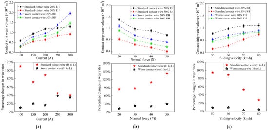
Figure 8.
CS wear volume and percentage changes in wear rates (High humidity to Low humidity). (a) Relative to current (Fn = 30 N, v = 60 km/h). (b) Relative to normal force (I = 200 A, v = 60 km/h). (c) Relative to sliding velocity (Fn = 30 N, I = 200 A).
Figure 8b shows that, with the change in normal force, the wv of the two friction pairs was higher in low humidity. In high humidity, the wv of the WSFR was higher than that of the NSFR; In low ambient humidity, the opposite was true. Regardless of the CW working surface profile or the ambient humidity, the normal force significantly influenced the wv. When the normal force increased from 20 N to 50 N, the wv decreased by 51.35% (high ambient humidity/SCFP), 36.15% (low ambient humidity/SCFP), 51.20% (high ambient humidity/WCFP), and 44.16% (low ambient humidity/WCFP), respectively. Increasing the normal force was one of the effective measures to inhibit CS wear, especially when the matching performance of the friction pair was poor. When the current and normal forces were constant, the increased sliding velocity increased the CS wear. Among them, the wv of the two friction pairs was still the highest in the low ambient humidity. Compared with Figure 8a,b, it was clear that the influence of sliding velocity on the wv was relatively weak. When the sliding velocity increased from 50 km/h to 80 km/h, the wv increased by only 0.483 × 103 mm3 (high ambient humidity/SCFP), 0.261 × 103 mm3 (low ambient humidity/SCFP), 0.305 × 103 mm3 (high ambient humidity/WCFP), and 0.290 × 103 mm3 (low ambient humidity/WCFP), respectively.
3.3. Other Critical Parameters
3.3.1. Arc Discharge Energy
Figure 9 depicts the arc discharge energy variation curves under different test conditions. In Figure 9a, the arc discharge energy rose significantly as the current increased. For both friction pairs, the arc discharge energy in low ambient humidity (20% RH) was higher than in high ambient humidity (50% RH). In both ambient humidity conditions, the arc discharge energy of the WCFP was always higher than that of the SCFP. In the range of current variation, the arc discharge energy of the WCFP was always the highest in the low ambient humidity, while the arc discharge energy of the SCFP was always the weakest in the high ambient humidity. When the loaded current was lower, the influence of ambient humidity on the arc discharge was more significant than the change in the contour of the CW working surface. However, when the current increased to 300 A, the effect of the change in the CW working surface profile became more significant.
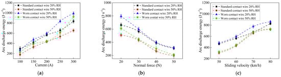
Figure 9.
Arc discharge energy. (a) Relative to current (Fn = 30 N, v = 60 km/h). (b) Relative to normal force (I = 200 A, v = 60 km/h). (c) Relative to sliding velocity (Fn = 30 N, I = 200 A).
Figure 9b,c display the variation in arc discharge energy with normal force and sliding velocity. The arc discharge energy increased with the decrease in normal force and the increase in sliding velocity. Under different test conditions, the relative relationship of arc discharge energy between the two friction pairs was consistent, namely, WCFP in low ambient humidity > SCFP in low humidity > WCFP in high ambient humidity > SCFP in high ambient humidity. This law was mainly because the effect of ambient humidity was more pronounced at a current of 200 A. As the normal force increased, the arc discharge energy of both friction pairs showed a decreasing trend under different ambient humidity. The increase in normal force expanded the contact area between the CS and the CW, and a higher normal force destroyed the oxide film on the contact surface, increasing the number of conductive spots between the friction pair, thus improving the contact state of the PCS. That was also why the normal force had a more significant impact on the arc discharge energy of the WCFP. Moreover, the increase in normal force improved the contact stability of the PCS, reducing the probability of offline arc discharge. So, the arc discharge energy continuously decreased with the increase in normal force.
When the current and normal force remained constant, an increase in sliding velocity would reduce the contact stability of the PCS, leading to increased system vibration and triggering the offline arc discharge, thus increasing system arc discharge energy. Especially for the WCFP, the unstable vibration caused by the increase in speed, combined with the original defects of the CW, made the arc discharge of the WCFP more significant and the arc energy higher, as shown in Figure 9c.
Under the same ambient humidity, the arc discharge energy of the WCFP was always higher than that of the SCFP. As the surface quality of the worn CW decreased due to arc ablation and damage, the contact state between the CS and the CW deteriorated, and the arc discharge was exacerbated. On the other hand, a layer of oxide film would form on the surface of the worn CW after ablation. When the normal force between the contact surfaces was insufficient to crush the oxide film, the number of conductive spots on the contact interface reduced, and the contact quality of the PCS would be lower. At the same time, the non-conductive property of the oxide film, to some extent, could be considered as ‘offline’, further exacerbating the arc discharge of the PCS.
For both friction pairs, the arc discharge energy in low ambient humidity was generally higher than in high ambient humidity. The decrease in ambient humidity reduced the smoothness of the friction interface, resulting in frequent offline arc discharge of the system. Although water molecules in high ambient humidity increased the probability of arc discharge to some extent [11,12,27], their influence was insufficient to change the law of arc discharge energy variation. In addition, the variation in arc discharge energy under different ambient humidity seemed related to the difference in contact resistance. In low ambient humidity, intensified arc discharge in the system promoted the formation of the oxide film on the friction interface, thereby increasing the membrane resistance. Moreover, the arc ablation on the friction surface deteriorated the surface quality of the material, reduced the number of conductive spots in the system, and thus increased the shrinkage resistance. The increase in contact resistance decreased the sliding conductivity of the friction pair [18]. So, the arc discharge energy was higher in low ambient humidity.
3.3.2. Temperature Rise
The temperature rise in the PCS mainly came from three sources: Joule heat caused by current loading, arc heat generated by arc discharge, and frictional heat caused by the mutual friction between the interfaces [28]. Among them, Joule heat and arc heat were the main reasons for the rise in system temperature, while the influence of frictional heat could be ignored [29]. In addition, the current in the PCS could only be transmitted through conductive spots, and a large amount of Joule heat could cause the conductive spots’ temperature to rise. At higher speeds, it was easy to induce electric sparks and arcs [30]. It could be seen that arc discharge would cause a temperature rise in the system, and a temperature rise in the system would also increase the probability of arc discharge.
The temperature rise curves of the friction pairs under different test conditions are shown in Figure 10. In Figure 10a, all four temperature rise curves showed upward trends as the current increased. For both friction pairs, the temperature rise in the PCS in low ambient humidity was always higher than in high ambient humidity. Under low ambient humidity conditions, the temperature rise in the WCFP was always higher than that of the SCFP. In high ambient humidity, when the current was less than or equal to 200 A, the temperature rise in the SCFP was higher; However, when the current exceeded 200 A, compared with the SCFP, the temperature rise in the WCFP was significantly higher. So, under high current conditions, the influence of the CW working surface profile on the temperature rise was more significant than ambient humidity. Combined with Figure 9a, when the current exceeded 200 A, the arc discharge of the WCFP became more intense in high ambient humidity. In addition, the surface defects of the worn CW reduced the number of conductive spots, resulting in the heating effect of Joule heating on the conductive spots at high currents, further promoting the arc discharge of the PCS.
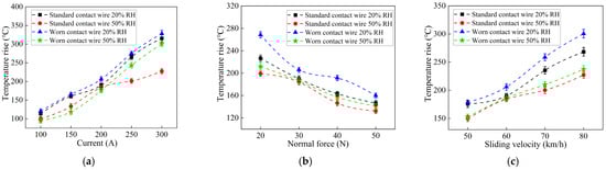
Figure 10.
Temperature rise. (a) Relative to current (Fn = 30 N, v = 60 km/h). (b) Relative to normal force (I = 200 A, v = 60 km/h). (c) Relative to sliding velocity (Fn = 30 N, I = 200 A).
The variation in temperature rise with normal force and sliding velocity is depicted in Figure 10b,c. The two figures show that the changing law of temperature rise and arc discharge energy was consistent, both decreasing with the increase in normal force and increasing with the growth of sliding velocity. When the loaded current was constant, according to the Joule heating calculation formula, the Joule heating in the system could be regarded as approximately constant. At this time, the main difference in temperature rise came from the variation in arc heat. The increase in normal force and the decrease in sliding velocity could improve the stability of the PCS and reduce the arc discharge rate, which led to a downward trend in the temperature rise in the system. The same was true for the temperature rise in the friction pairs under different ambient humidity.
3.3.3. Current-Carrying Efficiency
Figure 11 shows the current-carrying efficiency of the two friction pairs under different ambient humidity. It can be seen that with the increase in current and sliding velocity and the decrease in normal force, the current-carrying efficiency curves under various ambient humidity conditions showed a downward trend. Current-carrying efficiency can reflect the contact quality of the PCS. The higher the current-carrying efficiency, the more stable the pantograph–catenary contact, and the higher the current transmission rate. When other conditions remained constant, as the current increased, the Joule heating of the system increased, and the temperature of the friction pair rose. The high temperature burnt the surface of the CS and the CW, which reduced the quality of the contact surface. That increased the arc rate of the system and led to a decrease in current-carrying efficiency. Besides, the reduction in normal force and the increase in sliding velocity can cause unstable contact between the pantograph and the catenary, thereby inducing offline arcs. Arc ablation reduced the quality of the friction surface and caused a decrease in the current-carrying efficiency with the reduction in normal force and an increase in sliding velocity. In Figure 11, the relative magnitude of the system’s current-carrying efficiency under different test conditions was as follows: SCFP under high ambient humidity > WCFP under high ambient humidity > SCFP under low ambient humidity > WSFR under low ambient humidity.
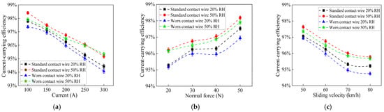
Figure 11.
Current-carrying efficiency. (a) Relative to current (Fn = 30 N, v = 60 km/h). (b) Relative to normal force (I = 200 A, v = 60 km/h). (c) Relative to sliding velocity (Fn = 30 N, I = 200 A).
From Figure 11, the system current-carrying efficiency in high ambient humidity was higher for the two friction pairs. Combined with Figure 9 and Figure 10, the arc discharge of the friction pairs was more intense in low ambient humidity. Arc ablation and Joule heating reduced the contact surface quality of the friction pairs, making the number of conductive spots at the friction interface lower than in high ambient humidity. Meanwhile, the oxide film generated by arc discharge hindered the current transmission, further reducing the current-carrying efficiency. In addition, in high ambient humidity, the adsorption of water molecules promoted the formation of a water film at the frictional interface, and some current could be transmitted through a conductive ‘water bridge’. Especially for the WCFP, water molecules filled the friction pair’s uneven contact surface. And the conductivity of water was better than that of air. Therefore, the current-carrying efficiency of the two friction pairs was higher in high ambient humidity.
Under the same ambient humidity, the WCFP’s current-carrying efficiency was lower than that of the SCFP. That was because of the poor surface quality of the worn CW and the less conductive spots when paired with the CS. At the same time, surface defects on the CW were more likely to trigger arc discharge in the friction pair, and arc ablation further damaged the friction surface, reducing the number of conductive spots in the system. In addition, the oxide film generated by arc discharge had a high membrane resistance, reducing the system’s current-carrying efficiency. Most notably, as depicted in Figure 11, when the current increased to 300 A, the WCFP’s current-carrying efficiency was higher than that of the SCFP under high ambient humidity. Under high current conditions, the Joule heat of the system increased, and an intensified arc discharge further increased the arc heat, resulting in a significant temperature rise in the system under the combined action of the two. The high temperature aggravated the softening of the material, which partially compensated for the arc ablation damage on the material surface, resulting in a slightly higher current-carrying efficiency of the WCFP at this current intensity.
3.3.4. Offline Rate
Figure 12 displays variations in the offline rate with changes in the experimental parameters. It is clear that as both the current and normal force increased, the offline rate concurrently decreased. Conversely, the offline rate increased with increases in the sliding velocity. With increased current, the Joule heating effect damaged the friction interface, raising the system’s arc discharge rate. As Joule and arc heat accumulated, the friction pair material gradually softened. Under the effect of the normal force, the number of conductive spots in the friction pair increased. It helped reduce the data points in the actual current, which were lower than 10% of the nominal current. So, the offline rate of the PCS gradually decreased with the increase in current. In Figure 12a, when the current reached 300 A, the WCFP’s offline rate showed an upward trend in the two ambient humidity conditions. Notably, the offline rate increased more pronouncedly in high ambient humidity.
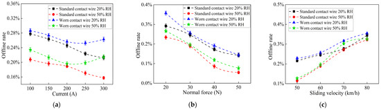
Figure 12.
Offline rate. (a) Relative to current (Fn = 30 N, v = 60 km/h). (b) Relative to normal force (I = 200 A, v = 60 km/h). (c) Relative to sliding velocity (Fn = 30 N, I = 200 A).
Combined with Figure 9, the surface quality of the worn CW was poor, reducing the number of conductive spots at the friction interface. When loading higher currents, it was more likely to induce arcing in the PCS, thus increasing the system’s offline rate. In return, the higher offline further promoted the occurrence of arcing. However, with the continuous accumulation of Joule and arc heat, the softened material improved the contact quality, and the current-carrying efficiency of the system increased accordingly. Therefore, in the dynamic change process, the WCFP exhibited the change law shown in Figure 9a, Figure 10a, Figure 11a and Figure 12a. With increases in normal force and decreases in sliding velocity, the current-carrying stability of the system improved, effectively suppressing the arc discharge. That reduced the probability of the pantograph and catenary going offline, as illustrated in Figure 12b,c.
In Figure 12, the offline rates of the two friction pairs in low ambient humidity were higher than in high ambient humidity. Under the same ambient humidity conditions, the offline rate of the WCFP was higher than that of the SCFP. Compared with high ambient humidity conditions, the decrease in the smoothness of the friction interface in low ambient humidity conditions was more likely to trigger pantograph–catenary arc discharge, causing arc ablation and damage on the contact surface of the friction pair, which increased the fluctuation of the real-time current, resulting in a higher pantograph–catenary offline rate in low ambient humidity. In addition, the oxide film generated at the friction interface in low ambient humidity was treated approximately as offline, leading to an increase in the offline rate. In the two ambient humidity conditions, surface defects on worn CWs resulted in lower contact quality when paired with a CS. Under the same test conditions, the WCFP was more prone to offline arcing, leading to a decrease in the current-carrying quality and an increase in the offline rate.
3.3.5. Contact Resistance
Figure 13 illustrates the variations in contact resistance with different experimental parameters. It shows that the contact resistance of the two friction pairs decreased with increases in current and normal force, but increased with increases in sliding velocity. When the current increased, the arc discharge of the system intensified. With the help of Joule heat and arc heat, the softening of the friction pair material increased the number or area of conductive spots between the CS and the CW, reduced the shrinkage resistance in the contact resistance, and caused the contact resistance to decrease with the increase in current. When the current and sliding velocity were unchanged by increases in normal force, the contact area at the friction interface increased, reducing the arc discharge rate of the friction pair and decreasing shrinkage and membrane resistance. Therefore, with increases in normal force, the contact resistance decreased continuously. When the sliding velocity increased with the current and normal force being constant, the contact stability of the PCS decreased, leading to intensified system arc discharge. The arc ablated the friction interface, reduced the contact quality between the CS and the CW, and increased the shrinkage resistance. At the same time, forming an oxide film on the friction interface increased the membrane resistance. So, as the sliding velocity increased, the contact resistance showed an upward trend.
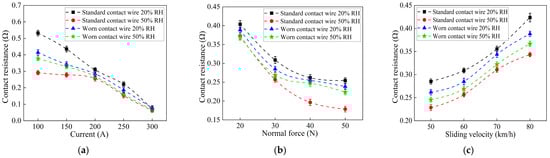
Figure 13.
Contact resistance. (a) Relative to current (Fn = 30 N, v = 60 km/h). (b) Relative to normal force (I = 200 A, v = 60 km/h). (c) Relative to sliding velocity (Fn = 30 N, I = 200 A).
The influence of ambient humidity on contact resistance is mainly reflected in two aspects: on the one hand, a decrease in ambient humidity will decrease the flatness of the contact surface, inducing arc discharge in the friction pair. Arc erosion affects the quality of the friction interface and promotes the formation of an oxide film on the contact surface. Meanwhile, the temperature rise caused by arc discharge and Joule heating will alter the contact area of the friction pair, thereby affecting the magnitude of the contact resistance. On the other hand, the high ambient humidity and the effect of current can increase the frictional chemical oxidation and electrochemical oxidation reactions at the friction interface [15,31,32]. Electrochemical reactions can ionize numerous ions, which exist in the water film and form a more conductive electrolyte environment, improving the conductivity of the water film and reducing contact resistance to a certain extent. However, the ions will slowly diffuse into the friction surface, causing material oxidation and promoting the formation of an oxide film. The oxide film, with high membrane resistance, will increase the contact resistance of the friction pair.
As illustrated in Figure 13, the contact resistance of the SCFP in low ambient humidity was higher than that of the WCFP. The analysis above indicated that in the low ambient humidity, the arc discharge of the WCFP was the most intense, and the softening effect of the arc heat and Joule heat on the material was particularly significant. When adding the normal force, the actual contact area of the WCFP was large, the number of conductive spots was higher, and the shrinkage resistance was relatively small. Although the arc discharge promoted the formation of an oxide film on the friction interface, the intense arc discharge made it hard to maintain the oxide film. So, the shrinkage resistance determined the contact resistance change law. In high ambient humidity, surface defects on the worn CW caused the arc discharge intensity of the WCFP to be higher than that of the SCFP. At this time, the softening effect of the arc heat and Joule heat generated by the arc discharge on the material was not significant, and the more intense arc discharge of the WCFP increased both shrinkage and membrane resistance, leading to its contact resistance being higher than that of the SCFP. The contact resistance for both friction pairs was higher in low ambient humidity. That was due to the increased arc discharge rate in low ambient humidity, where arc ablation damaged the CS and CW surfaces, increasing shrinkage and membrane resistance. Although in higher humidity environments, moisture and current promoted the electrochemical oxidation of the friction pair and increased the membrane resistance, the evaporation of water weakened its impact on the contact resistance when the temperature of the friction pair rose.
4. Discussion
4.1. Wear Mechanism of the CS
To further investigate the influence of the coupled effect of ambient humidity and pantograph–catenary matching performance on the CS wear mechanism, the CS wear scars were scanned using scanning electron microscopy (SEM) after the tests. After the experiments, a small cubic specimen (15 × 15 × 15 mm3) was cut from the commonly worn area of the CS. The high-magnification post-experiment images of the CS worn surface, with 500× magnification, were captured from this specimen. Figure 14 shows an example of the CS’s microscopic and macroscopic morphological features after the experiment. It illustrated the meaning of wearing scars on the CS surface in the figure and provided critical evidence for studying CS wear.
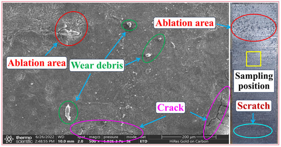
Figure 14.
Examples of CS SEM and macroscopic morphology images.
Figure 15 and Figure 16 provide the microscopic and macroscopic wear images of the CS after testing under different ambient humidity, with operating conditions of 200 A, 30 N, 60 km/h and 300 A, 30 N, 60 km/h. Figure 17 depicts the macroscopic wear images of the CW under corresponding operating conditions. In the high ambient humidity, when the loaded current was 200 A, from the macroscopic wear images in Figure 15a and Figure 17a, scratches and arc ablation marks distributed along the direction of CW rotation were observed on the surface of the SCFP’s CS. Especially in the upper part of the CS, the ablation pits were dense. On the surface of the corresponding standard CW, a few small scratches were also visible. The SEM image in Figure 15a shows that many fine abrasive particles existed on the CS surface, and arc ablation marks were scattered everywhere. Small cracks were also visible in some positions. When the CS matched with the worn CW, the burn marks in the macroscopic wear image of the CS and CW were more pronounced, and the scratches also existed on the surface of the CS and the CW, as shown in Figure 15b and Figure 17a. In the corresponding SEM image of the CS, the arc ablation marks were more severe compared to Figure 15a, with a wider ablation area and increased cracks. Compared with standard CWs, the surface quality of the worn CWs was worse, and the arc discharge, when matched with the CS, was more intense, resulting in heavier ablation marks on the CS surface.
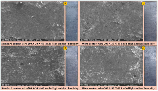
Figure 15.
Macro and microscopic wear morphology of CSs-High ambient humidity.
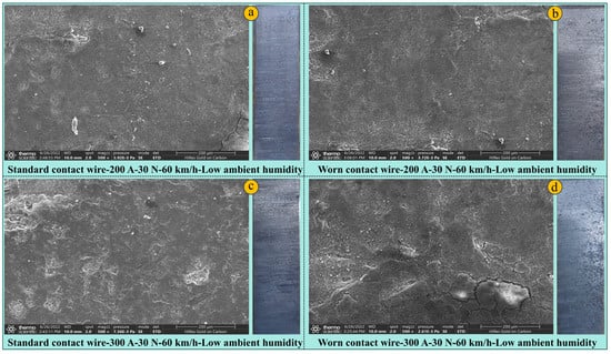
Figure 16.
Macro and microscopic wear morphology of CSs-Low ambient humidity.
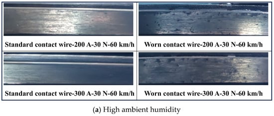
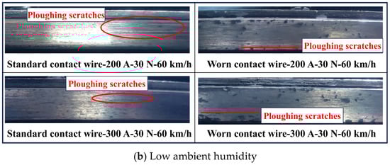
Figure 17.
Macroscopic wear morphology of CWs.
When the current increased to 300 A, the arc discharge intensity of the two friction pairs increased, and the ablation marks on the surfaces of the CS and the CW aggravated, as illustrated in Figure 15c,d and Figure 17a. At a current of 300 A, compared to the SCFP, the surface of WCFP’s CS and CW had more pronounced wear marks. A large amount of carbon powder was absorbed on the surface of the worn CW, and some ablation pits were even covered by carbon powder. On the CS surface, arc ablation almost covered the entire contact area, with dense erosion pits, and the surface color of the CS was darker. Under the severe arc ablation wear, the traces of abrasive wear were partially obscured, but scratches along the direction of CW rotation were still visible. In the CS’s microscopic image, the ablation marks on the CS surface of the WCFP were relatively heavy, while the abrasive particles were difficult to see. When the current was 300 A, the WCFP’s arc discharge was much stronger, resulting in increased arc ablation wear and determining the changing law of the CS wear volume.
Following the reduction in ambient humidity, the wear characteristics of the CSs and CWs for both friction pairs are presented in Figure 16. At a current of I = 200 A, the macroscopic wear images of the SCFP materials (Figure 16a and Figure 17b) revealed distinct ploughing scratches on the CS surface aligned with the CW rotation direction, accompanied by significant ablation marks in localized areas. The CW’s worn surface also exhibited numerous prominent ploughing scratches. The corresponding microscopic analysis demonstrated a substantial accumulation of abrasive particles on the CS surface, more pronounced ablation scars, and cracks predominantly located at edge regions.
As illustrated in Figure 16b and Figure 17b, the WCFP displayed enhanced arc ablation phenomena on the CS and CW surfaces under low humidity conditions. Furthermore, the worn CW surface showed fewer ploughing marks than the SCFP. SEM observations of the WCFP CS indicated intensified surface ablation and increased abrasive particle accumulation under reduced humidity. Comparative analysis between the two friction pairs’ materials under low humidity conditions revealed that the WCFP experienced more severe arc ablation on the CS surface, coupled with a marked decrease in abrasive particle concentration relative to the SCFP.
When the current increased to 300 A, both friction pair CSs exhibited significant intensification of arc ablation, while surface scratches persisted on both the CSs and CWs, as illustrated in Figure 16c,d and Figure 17b. Specifically, Figure 16c and Figure 17b reveal that the SCFP experienced pronounced aggravation of arc ablation on the CS and CW surfaces, with ablation scars showing widespread distribution. Concurrently, a reduction was observed in the abrasive particles on the CS’s micro-surface and the ploughing scratches on the CW surface. In comparison, the WCFP in Figure 16d and Figure 17b demonstrated fewer scratches on the CW surface. Nevertheless, it displayed more severe ablation wear characteristics, including larger and deeper cracks on the CS surface, indicating a substantial intensification of arc ablation wear on the CS.
A comparative analysis of Figure 15 and Figure 16 revealed that ambient humidity significantly influences the wear characteristics of CSs under identical experimental conditions. At a current of I = 200 A, both friction pair materials exhibited intensified ablation traces and ploughing scratches on their surfaces under low ambient humidity compared to high ambient humidity. Particularly for the SCFP, the CS’s micro-surface demonstrated a substantial increase in abrasive particles, and the CW surface showed more pronounced and densely distributed scratches. When the current increased to 300 A, the combined effects of low ambient humidity and increased current resulted in more severe surface ablation for both friction pair materials. However, scratches on the CW surface and abrasive particles on the CS surface decreased compared to those observed at 200 A under low ambient humidity.
Firstly, the influence of current variation on CS wear for two friction pairs was analyzed. When other parameters remained constant, an increase in current intensified the arc discharge of the friction pairs. The combined effect of arc heat and Joule heating led to a rise in the friction pair temperature. High temperatures and arc ablation exacerbated the electrical wear of the CSs, increasing their proportion in the overall wear and determining the trend in the CS wear volume. Consequently, as the current increased, the CS wear volume for both friction pairs showed an upward trend. However, the wear behaviors of the two friction pairs differed. For the SCFP, the temperature-induced material softening somewhat improved the contact quality of the friction pair in high currents. Therefore, as the current increased, the growth rate of the CS wear volume was more moderate. In contrast, for the WCFP, the negative impact of surface quality defects on the worn CW was further amplified with increasing current, resulting in a significantly higher arc discharge intensity. That led to a critical increase in the CS electrical wear, causing a notable rise in the CS wear volume for the WCFP under the 300 A condition.
Regarding the influence of ambient humidity on friction pairs, studies have shown that friction interfaces are typically uneven at the microscopic level. Under high ambient humidity, water molecules are absorbed into the pits of the contact surface, forming menisci. When an electric current was applied, the adsorbed water molecules were dissociated into hydroxide and oxygen ions, creating an electrolyte. Simultaneously, the hydroxide ions on the interface could promote further adsorption of water molecules, thereby intensifying tribo-chemical and electrochemical oxidation [16]. On the other hand, the copper surface underwent chemical modification through hydroxylation [33]. Under the influence of frictional energy, Cu-O-Cu bonds might form via dehydration reactions [34,35]. These high-energy bonds (Cu-O-Cu) were easily attacked by absorbed water molecules through hydrolysis reactions, forming CuO. The tribo-chemical reactions at the friction interface can be expressed as [36]:
Furthermore, research [15] indicated that when water molecules were ionized into hydroxide and oxygen ions, their diffusion into the material could induce the material’s electrochemical oxidation. Meanwhile, water molecules participated in the anodic oxidation process under charged conditions, causing copper to lose electrons and form divalent oxide. The electrochemical reaction can be displayed as [37]:
Additionally, according to the theory of oxidation reactions, (, ), at lower temperatures, the predominant copper oxide within the surface oxide film was . Under these conditions, the reaction at the friction interface can be represented by the following equation [38]:
However, when copper was heated above 150 °C, its oxide gradually transformed into [17]. That indicated that under high ambient humidity, water molecules contributed to the formation of copper oxide, forming a dense oxide film on the CW surface. Simultaneously, when the temperature of the friction pair was low, water molecules adhered to the material surface, forming a water film that prevented direct contact between the friction pair materials. Additionally, graphite particles generated by CS wear could provide lubrication in high ambient humidity. Considering the protection of graphite lubrication, water film, and oxide film, the wear of the pantograph CS and CW was relatively mild under high ambient humidity.
By contrast, when the ambient humidity was low, the absence of water molecules reduced the oxidation capability of O2, preventing the effective conversion of copper into copper oxides [17]. As a result, a complete oxide film could not form on the CW surface. And graphite particles produced by CS wear failed to provide reliable lubrication in low ambient humidity. Moreover, the original micro-surfaces of the pantograph CS and the CW are uneven, with their actual contact area consisting of numerous micro-asperities or small facets, as shown in Figure 18. In the absence of oxide films and lubrication, the hard micro-asperities on the CS surface continuously abraded the softer CW under higher shear stress, exacerbating the surface roughness of the CW, as illustrated in Figure 19. During high-speed sliding between the pantograph and CW, reduced surface smoothness could induce vibrations in the PCS and increase the occurrence of offline arcs when current was applied. Figure 20 shows the comparison of vibration acceleration of SCFP in high and low ambient humidity under the same operating conditions. By combining Figure 15 and Figure 16, it can be concluded that, compared to high ambient humidity, abrasive ploughing at the friction interface under low ambient humidity caused severe system vibrations, exacerbating the system’s arc discharge and significantly increasing the arc ablation wear of the CS.
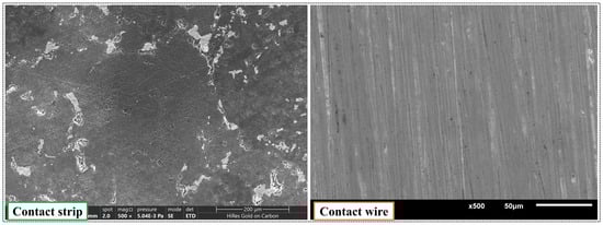
Figure 18.
Original SEM image of polished CS and CW.
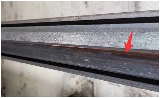
Figure 19.
Ploughing wear photo of the CW.
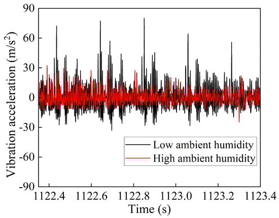
Figure 20.
Comparison diagram of vibration acceleration (SCFP).
In addition, during the experiment, when the CS moved relative to the CW, the contact points on the CS were relatively concentrated. However, the position of these contact points on the CW continuously changed as the CW rotated, leading to a more pronounced softening of the CS due to temperature rise. That reduced the hardness difference between the CS and the CW. After the CS surface was ablated and damaged, the edges generated by the CS’s micro-asperities ploughing on the CW surface, in turn, ploughed the CS surface. Meanwhile, the lack of lubrication and oxide film in low ambient humidity resulted in approximately dry friction between the CS and the CW. Under the combined effects of arc ablation and abrasive ploughing, the material damaged by ablation on the CS surface was scraped off, further degrading the matching performance of the PCS. The decline in pantograph–catenary matching performance continued to induce system arc discharge, exacerbating the arc ablation wear of the PCS. This cycle led to the CS’s increasingly severe arc ablation wear in low ambient humidity, with the CS’s wear volume remaining high. However, in low ambient humidity, the abnormal wear of the PCS did not occur instantaneously but required the accumulation of the aforementioned wear processes and time. That aligned with the phenomenon observed in subway operations, where significant abnormal wear of the PCS only became apparent after 2 to 5 days of continuous humidity levels below 25% [39].
For the WCFP, the flatness of the worn CW surface was inferior. In low ambient humidity, the abrasive wear of the CS, when paired with the worn CW, seemed to be higher than that of the SCFP. However, under current-carrying conditions, the more intense arc discharge of the WCFP caused higher wear on the CS and a higher temperature rise in the friction pair. Under the influence of graphite lubrication and material softening, the abrasive ploughing between the materials of the WCFP was attenuated. Meanwhile, the material softening partially compensated for the surface defects of the worn CW, improving the contact quality of the WCFP. Therefore, compared to the SCFP, the wear volume of the CS in the WCFP was smaller in low ambient humidity. However, when the ambient humidity increased, the surface defects of the worn CW provided favorable conditions for system arc discharge, leading to a significant increase in the arc ablation wear of the CS. Especially under high current conditions, the surface defects of the worn CW significantly enhanced arc discharge, leading to a rapid increase in arc ablation wear on the CS. Thus, the arc ablation wear became the dominant factor in the CS’s overall wear, ultimately determining the relative relationship of the CS wear volume. It was evident that as the CW’s working surface changed, the wear pattern of the CS also changed.
Based on the above analysis and the abnormal wear phenomena observed in the PCS of the metro, the experimental results revealed the wear mechanism of the PCS under low ambient humidity. When the humidity of the operating environment decreased, the micro-protrusions on the CS surface exhibited significant ploughing effects on the standard CW, leading to variations in vibration acceleration under different ambient humidity. The intensification of system vibration resulted in an increased arc discharge rate in low ambient humidity, where arc ablation and thermal effects exacerbated the arc-induced wear of the CS. Additionally, the higher shear stress in low ambient humidity caused the detachment of surface materials from the CS, indirectly increasing arc-induced wear. During the relative sliding of the PCS, hard abrasive particles at the friction interface aggravated the abrasive wear of the PCS. As the sliding distance increased, the decline in surface flatness further promoted arc discharge at the friction interface. Once a detrimental cycle was established, it led to a significant increase in arc-induced wear of the CS, which gradually became the root cause of abnormal wear in the PCS. However, if the low-humidity environment improved and reached a threshold humidity level, the graphite generated from the CS wear began to act as a lubricant. Simultaneously, the increased presence of water molecules facilitated the formation of an oxide film on the CW surface, which helped alleviate mutual ploughing at the friction interface, thereby improving the vibration conditions of the friction pair. Moreover, the enhanced quality of the contact surface increased the conductive spots in the friction pair, reducing the arc discharge rate and the PCS wear. As the condition of the friction surface gradually improved and ambient humidity rose, the combined effects of graphite lubrication, the oxide film on the CW surface, and the water film would gradually restore the wear of the PCS to normal levels.
Figure 21 presents the EDS analysis results of the SCFP’s CS after testing under the conditions of current I = 200 A, normal load (Fn) 30 N, and sliding velocity (v) 60 km/h in both ambient humidity conditions. It can be observed that under current-carrying conditions, the C element on the CS surface decreased after the test, whereas the O and Cu elements increased, with a higher proportion of O and Cu elements in low ambient humidity. Under the same operating parameters, the reduction in ambient humidity induced arc discharge in the friction pair. The high temperatures caused by Joule heating and arc heating promoted the oxidation reaction of the friction pair materials, leading to an increase in the content of O and Cu elements. Simultaneously, part of the C elements were oxidized and dissipated under high temperature and high humidity conditions, decreasing the C elements on the CS surface. Furthermore, under low ambient humidity, the abrasive effect of the surface asperities on the CWs was enhanced, exacerbating the CW wear. Some of the copper debris generated from the wear of the CW adhered to the CS surface during the friction process, thereby detecting more Cu elements. In high ambient humidity, the arc discharge of the friction pair was relatively weaker, and the oxidation reaction of the friction pair materials was less pronounced than in low ambient humidity, resulting in relatively lower contents of O and Cu elements in high ambient humidity conditions.
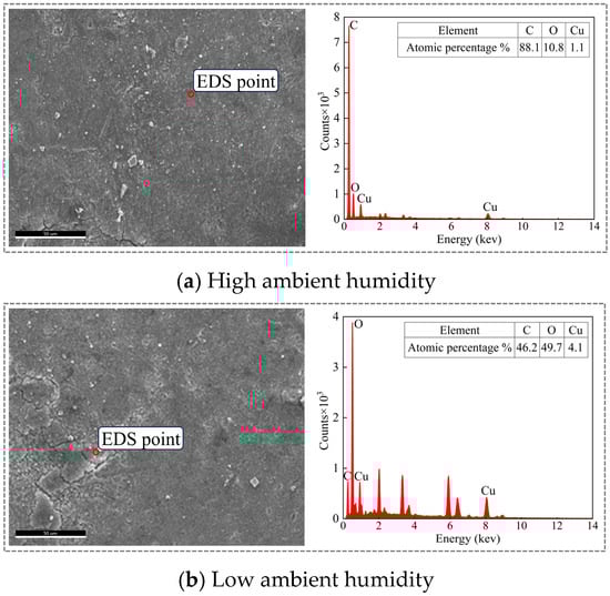
Figure 21.
EDS analysis of the SCFP (I = 200 A, Fn = 30 N, v = 60 km/h).
Based on the experimental results, it can be concluded that in environments with low ambient humidity, the good matching performance between the pantograph CS and the CW did not necessarily contribute to the stable operation of the PCS. On the contrary, the PCS was prone to abnormal wear over time under low ambient humidity conditions. When the matching performance of the PCS deteriorated to a threshold critical state, the arc discharge of the system intensified. At this stage, the lubricating effect of graphite and the softening effect of the temperature rise in the friction pair on the material partially alleviated the negative impact of the low ambient humidity environment on the PCS, thereby reducing the wear of the pantograph CS. These experimental findings revealed that the wear of the PCS was not only affected by operational conditions but also significantly influenced by factors such as ambient humidity and the surface morphology of the friction pair materials.
Ref. [40] analyzed the causes of abnormal wear in the rigid PCS of metros. The factors inducing abnormal wear in the rigid PCS were numerous, relating not only to the system’s structure, materials, and arrangement but also closely associated with vehicle track conditions, wheel–rail relationships, environmental factors, and operational practices. During the operation of the PCS, unreasonable parameter settings might lead to a decline in the system’s matching performance, triggering a vicious cycle that results in abnormal wear. That indirectly explained why abnormal wear of the PCS occurred in some metro lines but not others. Regarding the issue of abnormal wear under winter (low-humidity) conditions, field observations indicated that during the initial stages of reduced humidity in tunnels, the abnormal wear of the PCS was not significant [41]. However, as time accumulated, abnormalities such as pantograph CS chipping, accelerated wear of the CS, cracks in the pantograph horn, hard spots on the CW, burrs on the CW, and grayish-white lines on the contact surface gradually became apparent.
Additionally, in winter (low-humidity conditions), the environmental conditions inside the tunnels deteriorated, and the dirty busbar led to poor heat dissipation at the pantograph–catenary junction. Coupled with the significant temperature difference between the inside and the outside of the tunnel in winter, the vaporization of pantograph–catenary materials under high temperatures, followed by environmental cooling, caused the metal to deposit on the surface of the pantograph CS. That resulted in adhesion and abrasive wear in station lines and low-speed sections. During winter or periods of significant temperature fluctuations, the ballast in fracture zones might experience an uplift or subsidence exceeding 10 mm [9]. Furthermore, temperature drops could lead to changes in the CW angle or issues such as jamming and hard spots [42]. These factors also contributed to the differences in pantograph–catenary wear between winter and non-winter months.
The experimental results indicated that under low ambient humidity conditions, the primary cause of abnormal wear in the PCS was the ploughing of the CW by high-hardness micro-asperities on the CS surface, which led to a decline in the flatness of the friction interface and subsequently exacerbated system vibrations. Therefore, measures that can mitigate system vibrations or reduce mutual ploughing between the pantograph and catenary, such as enhancing lubrication at the friction interface or minimizing the hardness difference between the pantograph and catenary materials, are beneficial for reducing wear. In addition, the experimental results also revealed that when ambient humidity decreased, moderate arc discharge could reduce mutual ploughing between the pantograph and catenary. So, when the ambient humidity is low in winter, it might be advisable to induce moderate arc discharge by adjusting the working surface profile of the PCS. The appropriate temperature rise in the system and CS wear could also alleviate the ploughing effect at the friction interface. In conclusion, when formulating measures to reduce pantograph–catenary wear, it is necessary to make reasonable adjustments based on the specific conditions of different metro lines.
4.2. Influence of Test Parameters on the Friction Coefficient (μ)
The μ primarily consists of three parts [26]: the ploughing part, the deformation part, and the adhesion part, and its numerical value depends on the size of the three parts and the proportion of each part. Among these, the ploughing part arises from the action of abrasive particles and micro-asperities on the harder contact surface against the softer surface; The deformation part originates from the interaction between micro-asperities on the contact surfaces; The adhesion part is generated by the adhesion between two relatively sliding surfaces and is mainly influenced by the contact surface conditions and lubrication status.
In Figure 7, which illustrates the variation in the μ with experimental parameters, the μ of both friction pairs exhibited a decreasing trend as the current increased. The electric current application altered the proportion of various parts in the μ. With increasing current, the intensified arc discharge damaged the friction interface and increased the deformation part of the μ. Under weaker arc discharge, an oxide film could form on the friction interface, which helped reduce the adhesion part. However, as the current continued to rise, the intensified arc discharge made it hard to maintain the oxide film, thereby failing to reduce the adhesion part effectively. Besides, with the help of Joule heating and arc heating, the softening of materials reduced the ploughing part. Notably, without current, the pantograph CS and CW formed a traditional mechanical friction pair, where the temperature rise during sliding was minimal [43], and the friction pair materials hardly softened. Consequently, the ploughing part of the μ was inevitably higher than that under current-carrying conditions, and it constituted the primary part of the μ. So, with weaker arc discharge, the reduction in the ploughing and adhesion parts outweighed the increase in the deformation part, causing the μ to decrease with increasing current. When the current further increased, intensified arc discharge softened the materials, leading to a significant reduction in the ploughing part compared to the increases in the deformation and adhesion parts, resulting in a downward trend in the μ.
In Figure 7b, the μ continuously decreased with the increase in normal force. Increased normal force effectively suppressed the arc discharge and readily induced plastic deformation and brittle fracture of the asperities on the contact surface [24]. The plastic deformation polished the contact surface asperities, effectively controlling the deformation part. After the arc discharge was suppressed, the temperature rise in the system decreased, leading to an increase in the ploughing part. However, with the weakening of arc discharge, the oxide film on the friction interface was maintained, and the lubrication provided by graphite reduced the adhesive part. During the increase in normal force, with reduced deformation and adhesive parts, the μ continuously declined.
With a fixed normal force and current, an increase in sliding velocity reduced the contact stability of the friction pairs, intensified the arc discharge, and adversely affected the deformation part. However, under high sliding velocities, arc-induced temperature rise softened the friction materials and reduced the ploughing part. As the sliding velocity increased, the reduced ploughing part caused the μ to decline.
Previous studies [15,18] had demonstrated that ambient humidity significantly influenced the μ. As shown in Figure 7, the μ of both friction pairs was generally higher under high ambient humidity. Notably, in the absence of current, the SCFP exhibited a higher μ in low ambient humidity. In the process of pure mechanical sliding, higher ambient humidity promoted the adsorption of water film on the friction interface, which inhibited surface oxidation and consequently reduced the μ [18,44]. Additionally, water molecules in the air were adsorbed between carbon atomic layers, reducing the intermolecular forces between the carbon layers through the passivation effect of water, making it easier for the carbon layers to slip. When sufficient water molecules were adsorbed, the layered slip structure was disrupted, forming an amorphous structure and generating a lubricating effect [45,46], thereby reducing the μ. Thus, for the SCFP under no-current conditions, the μ was relatively lower in high ambient humidity.
For the WCFP, however, the μ was significantly higher under high ambient humidity. That was due to surface defect-induced surface roughness enhancement of the worn CW, leading to a higher μ when paired with the pantograph CS. During pure mechanical sliding, the ploughing effect on the friction interface was more significant, and the shear stress on the material surface remained higher. Under continuous friction, the surface asperities on the worn CW underwent progressive shear removal. Especially in low ambient humidity, the lack of lubrication exacerbated this cutting effect, resulting in the lowest μ for the WCFP.
Under the applied current, lower ambient humidity promoted the arc discharge of the system. The intense arc-induced temperature rise softened the friction material, thereby reducing the abrasive part of the μ. In addition, high ambient humidity and current jointly promoted the formation of oxide film on the friction surface. The friction film under high ambient humidity exhibited hydrophilicity, facilitating partial graphite slip. Meanwhile, the adsorbed water between rough contact surfaces generated capillary forces, introducing additional friction forces in regions where carbon layers did not slide, increasing the μ [47].
Furthermore, under high ambient humidity, the adsorption of water film formed microscopic menisci around surface asperities. The meniscus force (an additional pressure induced by curved liquid interfaces) enhanced the effective normal force, increasing the μ [48]. According to Xie et al. [49], when an electric field was applied, the adsorbed water film thickened, and the additional electric field effect amplified the meniscus force, leading to a further rise in μ [50]. Moreover, when ambient humidity was sufficient to facilitate multilayer water adsorption, the surface tension enhanced the adhesion force, contributing to a higher μ [51].
A comparison between different CWs revealed that the SCFP exhibited a higher μ. Under the two ambient humidities, the WCFP experienced more intense arcing, leading to pronounced material softening and a significant reduction in the abrasive part of the μ. In contrast, for the SCFP, arc ablation gradually degraded the contact surface quality, narrowing the gap in the deformation part between the two friction pairs during electrical sliding. Consequently, the WCFP demonstrated a lower μ due to its diminished abrasive part.
4.3. Influence of Test Parameters on the CS Wear Volume (wv)
Figure 7 illustrates the variation in CS wear volume (wv) with experimental parameters, while Figure 22 and Figure 23 present correlation heatmaps between the wv and various parameters for both friction pairs under different ambient humidity. The numerical values represent Pearson correlation coefficients, where positive values indicate positive correlations and negative values denote negative correlations. According to the Pearson correlation coefficient definition, values between 0.6 and 0.8 signify a strong correlation, whereas those in the range of 0.8 to 1.0 indicate a significantly strong correlation.
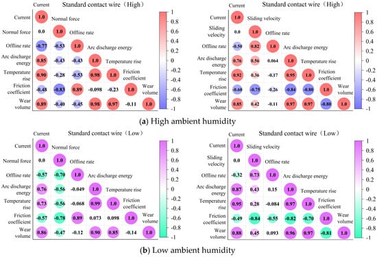
Figure 22.
Correlation analysis of the SCFP.
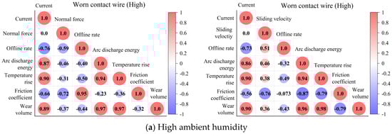
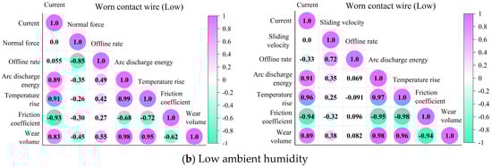
Figure 23.
Correlation analysis of the WCFP.
In Figure 22 and Figure 23, the wv exhibited significantly strong positive correlations with current, arc discharge energy, and temperature rise. With all other conditions held constant, increasing current intensified the arc discharge and enhanced arc-induced CS wear. For the SCFP, when the current was below 200 A, the wear volume increased significantly with rising current. However, once the current exceeded 200 A, the wear volume stabilized. This phenomenon occurred because, despite intensified arc ablation at higher currents, the combined effects of intensified arc discharge and Joule heating induced material softening, improving interfacial contact quality and thus suppressing arc discharge intensity. Consequently, the growth rate of arc-induced wear diminished, resulting in a gentle increase in wear volume. In contrast, for the WCFP, the wear volume increased rapidly with the current. This accelerated wear was due to surface defects on the worn CW, which provoked more severe arc discharge under high currents, significantly exacerbating arc-induced CS wear.
For both friction pairs, forming a sufficient oxide film on the friction interface was difficult in low ambient humidity. During the relative sliding motion between the pantograph CS and the CW, the hard asperities on the CS continuously abraded the CW surface, reducing its smoothness. When an electrical current was applied, the degraded matching performance between the CS and CW intensified the arc discharge, leading to a significant increase in arc-induced CS wear.
Furthermore, the shear stress at the friction interface was notably higher under low ambient humidity [13]. The material on the CS surface damaged by arc ablation became more prone to detachment, generating abrasive debris that exacerbated the abrasive wear in the PCS. Consequently, the wv in low ambient humidity was significantly higher than that observed under high ambient humidity. Additionally, the absence of a complete oxide film in low ambient humidity allowed the CS to more aggressively abrade the worn CW surface, further increasing its roughness. Surface deterioration enhanced the WCFP’s arc discharge. Simultaneously, the abrasive ploughing effect between the friction surfaces of the WCFP was more significant, resulting in apparently higher CS wear volume of the WCFP under low ambient humidity.
However, compared with the SCFP, the more intense arc discharge caused by inherent defects in the worn CW elevated the temperature of the system. Particularly under high-current conditions, the resulting temperature rise softened the material, partially mitigating the abrasive effect between asperities at the friction interface. Therefore, with lower currents, the SCFP exhibited more severe CS wear in low ambient humidity. Conversely, under high-current conditions, the substantial increase in arc-induced wear led to a higher CS wear volume of the WCFP.
With constant current and sliding velocity, increasing the normal force effectively suppressed the pantograph–catenary arc discharge, reducing arc-induced CS wear. In current-carrying conditions, the increase in abrasive wear of the CS remained limited. So, the w-v demonstrated a decreasing trend with elevated normal forces. Due to the more significant arc suppression effect of normal force on the WCFP, the arc ablation wear reduction in the CS was higher than that of the SCFP under identical conditions.
In low ambient humidity, the abrasive wear of CSs was more significant due to the influence of normal forces. Concurrently, arc ablation damage and high interfacial shear stress promoted material detachment from the CS surface, further accelerating the CS wear and maintaining consistently high wear volumes. However, compared to the SCFP, the worn CW surface defects induced more intense arc discharge, with subsequent temperature rise causing material softening that mitigates interfacial abrasion. This mechanism explained the lower wear volume observed on the WCFP’s CS in low ambient humidity. Conversely, under high ambient humidity, the surface defects of the worn CW significantly promoted arc discharge, leading to markedly increased arc-induced wear. That resulted in substantially higher CS wear volume for the WCFP than the SCFP in high ambient humidity. As illustrated in Figure 8c, elevating sliding velocities induced unstable contact in the PCS, triggering increased arc discharge and consequent growth in arc-induced wear. Under low ambient humidity, the SCFP’s CS maintained the highest wear volume across the sliding velocity range. This phenomenon stemmed from the combined effects of heightened interfacial shear stress and intensified abrasive wear under low ambient humidity, which indirectly exacerbated arc-induced damage, producing wear volumes significantly exceeding those observed in the other three operational conditions.
5. From Mechanism Exploration to Intelligent Modeling
This study systematically reveals the coupling effects of environmental humidity and contact wire profile on the wear mechanisms of pantograph contact strips, thereby deepening the understanding of tribological behavior under complex operating conditions. The high-quality, high-confidence dataset generated here provides an indispensable physical foundation and validation benchmark for the subsequent application of data-driven methods in performance prediction and intelligent optimization. With materials and engineering research having entered the data-centric “Fourth Paradigm” [52], tribology must also evolve accordingly.
Constructing Surrogate Models for Intelligent Optimization: The experimental data from this study can first be used to train machine learning surrogate models (e.g., Gaussian Process Regression). These models efficiently map the complex nonlinear relationships between input parameters (humidity, material profile, load, etc.) and output responses (wear rate, contact resistance, etc.). Subsequently, intelligent algorithm frameworks such as Bayesian Optimization [53] can be introduced. By using this surrogate model as the objective function, adaptive sampling and global optimization can be performed. This approach identifies optimal profile designs or operating parameter combinations with significantly greater efficiency than traditional methods, drastically reducing the cost and duration of subsequent physical experiments.
Developing Intelligent Models That Incorporate Physical Knowledge: To enhance the physical interpretability of purely data-driven models and their extrapolation reliability under novel conditions, advanced paradigms such as Physics-Informed Neural Networks should be explored [54]. These methods allow the underlying physical laws revealed in this study (e.g., the mechanism of oxide film formation and destruction within specific humidity ranges) to be embedded into deep learning models as differential equation constraints or loss function terms. This facilitates the development of a pantograph–catenary system’s wear digital twin that integrates physical mechanisms with data algorithms, achieving a leap from phenomenological description to mechanism modeling.
Moving Towards Predictive Maintenance in Engineering Applications: Ultimately, the outputs of the aforementioned intelligent models can be integrated with system condition-monitoring data to support predictive health management. Just as machine learning has been successfully applied to the operation and maintenance of complex systems like electric vehicles [55], model-based prediction of pantograph wear status and remaining useful life assessment holds the potential to advance rail transit power supply systems from “scheduled maintenance” to “predictive and optimized maintenance.”
In summary, the value of this work lies not only in its mechanism discoveries but also in laying the foundation for a complete technical pathway: from acquiring fundamental data through physical experiments to constructing intelligent models for efficient optimization. This represents the inevitable direction for addressing the complex engineering challenge of multifactor coupled wear in pantograph–catenary systems.
6. Conclusions and Outlooks
This paper comprehensively considered the potential effects of pantograph–catenary matching performance and ambient humidity on CS wear. Using a high-speed current-carrying friction and wear test rig, the wear mechanisms of pantograph CSs were systematically explored under the coupled influence of ambient humidities and matching performance. The experimental results led to the following conclusions:
- (1)
- Under high ambient humidity, the CW working surface profile determined the CS wear rule, and electrical wear was dominant. The CS wear volume of the WCFP (max. 1.466 × 103 mm3) was higher than the SCFP (max. 0.923 × 103 mm3).
- (2)
- Under low ambient humidity, when the current I ≤ 200 A, ambient humidity was the critical factor influencing the CS wear law, and the CS of the SCFP exhibited maximum CS wear volume (max. 1.181 × 103 mm3) due to combined abrasive and arc-induced wear. When the current I > 200 A, the CW working surface profile became the decisive parameter; especially after the current exceeded 300 A, its influence became more significant. With significant arc-induced wear, the CS of the WCFP demonstrated the highest CS wear volume (max. 1.980 × 103 mm3).
- (3)
- The abrasive ploughing effect at the friction interface was more pronounced in low ambient humidity, and the system vibration caused by the decrease in CW surface flatness increased, exacerbating the arc discharge of the friction pair. Under combined arc ablation and abrasive wear effects, the CS wear volume consistently exceeded that in high ambient humidity.
- (4)
- As a consumable component, the CS in service generally forms diverse external profiles; future studies should systematically investigate the PCS current-carrying friction and wear performance under multifactor conditions, i.e., different combinations of CS/CW profiles, ambient humidity, and other variables.
- (5)
- Given the inherent characteristics of friction and wear testing—namely, high cost and long cycle times—the traditional “trial-and-error” optimization approach is inefficient. Future research can build upon the dataset constructed in this study, advancing along a path that combines model-driven and data-driven approaches.
Author Contributions
Writing—original draft preparation, writing—review and editing, W.R.; the doctoral supervisor of the first author, G.C.; supervision, H.Y.; Supervision, D.Z.; funding acquisition, S.H.; data collection, L.Z.; funding acquisition, Y.H.; Investigation, J.Y. All authors have read and agreed to the published version of the manuscript.
Funding
This work was supported by the Key Development Projects of the Sichuan Provincial Science and Technology Plan (2022YFG0135), the National Natural Science Foundation of China (No. 52305194; No. 52375168; No. 52175189), Doctoral Talent Project of Chengdu Technological University (2024RC041), Sichuan Province International Science and Technology Innovation Cooperation Project (No. 2025YFHZ0076), and the central government guides local science and technology development projects (No. 2024ZYD0119).
Data Availability Statement
The data presented in this study are available on request from the corresponding author due to the data is confidential.
Conflicts of Interest
The authors declare that they have no known competing financial interests or personal relationships that could have appeared to influence the work reported in this paper.
Abbreviations
The following abbreviations are used in this manuscript:
| μ | Friction coefficient |
| CS | Contact strip |
| CW | Contact wire |
| SCFP | Standard contact wire/contact strip friction pair |
| WCFP | Worn contact wire/contact stirp friction pair |
| PCS | Pantograph–catenary system |
| Wear volume of the contact strip | |
| SEM | scanned electron microscopy |
References
- China Association of Metros. Summary and analysis of urban rail transit lines in mainland China in 2024. Mod. Urban Transit 2025, 129–130. [Google Scholar]
- Zhu, W.P. Research on wear rate of pantograph carbon slide in Shenzhen metro line 11. Railw. Locomot. Car 2018, 38, 121–126. [Google Scholar]
- Li, J.; Lu, H.L.; Wei, L.J. Analysis and rectification of abnormal pantograph-catenary wear on Nanning metro line 2. Equip. Manuf. Technol. 2022, 329, 148–152. [Google Scholar]
- Zhou, C.Y.; Liu, C. Research for abnormal wear of pantograph in Beijing subway line 6. Railw. Locomot. Car 2019, 39, 51–54. [Google Scholar]
- Wang, H.Y. Causes and solutions of pantograph carbon strip abnormal wear on Beijing metro line 6 west extension. Urban Mass Transit 2023, 26, 44–49. [Google Scholar]
- Li, J.D. Discussion on abnormal pantograph-catenary wear on Nanjing metro line 4. TranspoWorld 2020, 552, 13–14. [Google Scholar]
- Song, X.Y.; Li, G.; Gao, Z.L. Analysis on Abnormal Wear of Pantograph and Catenary of Zhengzhou Metro Line 3. Henan Sci. Technol. 2021, 40, 77–79. [Google Scholar]
- Qiu, M.W.; He, J.Q. Analysis and solution on abnormal wear of pantograph and catenary of Guangzhou Metro Line 3. Technol. Mark. 2023, 30, 57–60. [Google Scholar]
- Guo, G.; Yang, X.M. Mechanism and prevention suggestions of abnormal wear in rigid catenary systems for urban rail transit. Sci.-Tech. Dev. Enterp. 2022, 100–102. [Google Scholar]
- Zhi, X.S.; Zhou, N.; Cheng, Y.; Wang, X.; Wei, H.; Chen, G.; Zhang, W. Effect and behaviors of ambient humidity on the wear of metal-impregnated carbon strip in pantograph-catenary system. Tribol. Int. 2023, 188, 108864. [Google Scholar] [CrossRef]
- Li, H.X.; Ji, D.H.; Shen, M.X.; Xiao, Y.; Zhao, H.; Liu, X.; Xiong, G. Effect of environmental humidity on tribological behavior of carbon/copper current-carrying sliding contact pairs. Tribology 2022, 42, 709–718. [Google Scholar]
- Wang, M.; Guo, F.Y.; Wang, Z.Y.; Chen, Z.H.; Xue, Y.M. Study on the wear characteristics of slide plate under wet conditions. High Volt. Appar. 2018, 54, 292–296. [Google Scholar]
- Huang, M.; Yang, B.; Rong, Y.X.; Zhao, L.; Xiao, S. Study on friction and wear properties of copper-impregnated carbon slide plate under different humidity conditions. Tribol. Trans. 2023, 66, 953–964. [Google Scholar] [CrossRef]
- Wu, R.X.; Song, C.F.; Wu, H.H.; Lv, B.; Zhang, Y.; Zhang, Y. Effect of relative humidity on the current-carrying tribological properties of Cu-C sliding contact pairs. Wear 2022, 492–493, 204219. [Google Scholar] [CrossRef]
- Sun, Y.X.; Song, C.F.; Liu, Z.L.; Li, J.; Sun, Y.; Shangguan, B.; Zhang, Y. Effect of relative humidity on the tribological/conductive properties of Cu/Cu rolling contact pairs. Wear 2019, 436–437, 203023. [Google Scholar] [CrossRef]
- Song, C.F.; Sun, Y.X.; Zhang, Y.Y.; Pang, X.; Chen, T.; Sun, C.; Zhang, Y. Current-carrying property and damage mechanism of rolling contact pairs in different water conditions: From vapor to liquid. Wear 2021, 477, 203857. [Google Scholar] [CrossRef]
- Hu, Z.L.; Chen, Z.H.; Xia, J.T. Study on surface film in the wear of electrographite brushes against copper commutators for variable current and humidity. Wear 2008, 264, 11–17. [Google Scholar] [CrossRef]
- Ji, D.H.; Li, H.X.; Shen, M.X.; Zhao, H.P.; Hu, Q.; Liu, X.L.; Xiong, G.Y. The role of relatively humidity in friction and wear behaviors of carbon sliding against copper with electric current. Surf. Topogr. Metrol. Prop. 2021, 9, 048001. [Google Scholar] [CrossRef]
- Ji, D.H.; Xiao, L.; Xiong, G.Y.; Xiao, L.; Li, Q. Current-carrying tribological characteristics of pantograph-catenary system contact pair in extreme temperature/humidity environments. J. Railw. Sci. Eng. 2024, 21, 4735–4745. [Google Scholar]
- Ren, W.J.; Chen, G.X.; Dong, B.J.; Song, Q.; Feng, X.; Li, L.; Yang, H.; He, Q. Experimental study of the effect of contact line profiles on the wear mechanism of a skateboard. Tribol. Int. 2024, 192, 109317. [Google Scholar] [CrossRef]
- Zhu, G.Y. Study on the Evolvement of Pantograph-Catenary Arcing in High-Speed Railway and Its Numerical Modeling. Ph.D. Thesis, Southwest Jiaotong University, Chengdu, China, 2018. [Google Scholar]
- Hu, D.C.; Sun, L.M.; Shangguan, B.; Zhang, Y.Z. Effects of arc discharge on friction and wear properties of metal-impregnated carbon strip sliding against Cu trolley under electric current. Tribology 2009, 29, 36–42. [Google Scholar]
- Chen, G.X.; Yang, H.J.; Zhang, W.H.; Wang, X.; Zhang, S.; Zhou, Z. Experimental study on arc ablation occurring in a contact strip rubbing against a contact wire with electrical current. Tribol. Int. 2013, 61, 88–94. [Google Scholar] [CrossRef]
- Mei, G.M. Impact of voltage on the electric sliding tribological properties of current collectors against overhead lines. Wear 2021, 474–475, 203868. [Google Scholar] [CrossRef]
- Zhang, D.D.; Li, X.B.; Zhang, H.; Zhang, C. Simulation research on transient process of subway train pantograph-catenary offline. J. Shanghai Univ. Eng. Sci. 2022, 36, 405–409+17. [Google Scholar]
- Suh, N.P.; Sin, H.C. The genesis of friction. Wear 1981, 69, 91–114. [Google Scholar] [CrossRef]
- Lin, J.; Qiu, Z.; Wang, J.; Li, D. Effect of humidity on output performance of triboelectric nanogenerator: An experimental study. Chin. J. Vac. Sci. Technol. 2020, 40, 919–925. [Google Scholar]
- Jia, S.G.; Liu, P.; Ren, F.Z.; Tian, B.H.; Zheng, M.S.; Zhou, G.S. Wear behavior of Cu-Ag-Cr alloy wire under electrical sliding. Mater. Sci. Eng. A 2005, 398, 262–267. [Google Scholar] [CrossRef]
- Zhou, Y.; Wei, W.; Gao, G.; Wu, J.; Wu, G. Characteristics of Temperature Rise of Pantograph Strip in Electric Contact System between Pantograph and Catenary. J. China Railw. Soc. 2019, 41, 74–80. [Google Scholar]
- Wang, W. Measurement and Analysis of the Transient High Temperature on High-Speed Sliding Electrical Contact Surface. Master’s Thesis, Yanshan University, Qinhuangdao, China, 2015. [Google Scholar]
- Sun, Y.X.; Yue, Y.; Song, C.F.; Song, L.; Zhang, Y. Effect of Relative Humidity on Triboelectric Wear of Copper. J. Henan Univ. Sci. Technol. (Nat. Sci.) 2018, 39, 1–4+117. [Google Scholar]
- Mendoza, C.; Plata, A.; Lizarazo, Z.; Chacón, C.A. Analysis of the influence of the applied voltage and the scan speed in the atomic force microscopy local oxidation technique. J. Phys. Conf. Ser. 2016, 687, 012039. [Google Scholar] [CrossRef]
- Maw, W.; Stevens, F.; Langford, S.C.; Dickinson, J.T. Single asperity tribochemical wear of silicon nitride studied by atomic force microscopy. J. Appl. Phys. 2002, 92, 5103–5109. [Google Scholar] [CrossRef]
- Lichtenberger, O.; Woltersdorf, J. On the atomic mechanisms of water-enhanced silicon wafer direct bonding. Mater. Chem. Phys. 1996, 44, 222–232. [Google Scholar] [CrossRef]
- Yeo, C.Y.; Xu, D.W.; Yoon, S.F.; Fitzgerald, E.A. Low temperature direct wafer bonding of GaAs to Si via plasma activation. Appl. Phys. Lett. 2013, 102, 054107. [Google Scholar] [CrossRef]
- Song, C.F.; Li, X.Y.; Dong, H.S.; Yu, B.; Wang, Z.; Qian, L. Nondestructive tribochemistry-assisted nanofabrication on GaAs surface. Sci. Rep. 2015, 5, 9020. [Google Scholar] [CrossRef] [PubMed]
- Ryu, Y.K.; Garcia, R. Advanced oxidation scanning probe lithography. Nanotechnology 2017, 28, 142003. [Google Scholar] [CrossRef]
- Spry, W.J.; Scherer, P.M. Copper oxide film formation at a sliding carbon-copper interface. Wear 1961, 4, 137–149. [Google Scholar] [CrossRef]
- Wu, T.H.; Xu, W.Z.; Qin, D.C.; Niu, C. Research on the issue of the abnormal pantograph and OCS wear on Tianjin metro line 6. Mod. Urban Transit 2024, 50–56. [Google Scholar]
- Zou, D.; Zhong, S.C.; Geng, Y.; Cheng, Y.; Mo, Z.; Xu, K.; Song, B.; Cheng, B.; Zhang, S.; Wang, Z.; et al. Status analysis and prevention-treatment technology study of abnormal wear of pantograph catenary system in urban rail transit. J. Mech. Eng. 2023, 59, 152–178. [Google Scholar]
- Li, F.; Ge, F.; Guan, Q.H.; Li, Y. Vehicle countermeasures when pantograph-catenary relationship deteriorates. Electr. Locomot. Mass Transit Veh. 2020, 43, 78–80+3. [Google Scholar]
- Huang, S.Z.; Xiao, J.Y.; He, Z.T. Improvement and prevention measures for abnormal wear of pantograph and contact line in the laterperiod of urban rail transit operation. Mod. Urban Transit 2022, 5, 68–72. [Google Scholar]
- Ding, T.; Chen, G.X.; Bu, J.; Zhang, W. Effect of temperature and arc discharge on friction and wear behaviours of carbon strip/copper contact wire in pantograph-catenary systems. Wear 2011, 271, 1629–1636. [Google Scholar] [CrossRef]
- Sun, Y.X.; Song, C.F.; Zhang, Y.Y.; Li, M.; Zhang, Y. Oxidation on the current-carrying rolling surface and its subsequent impact on the damage of Cu contact pairs in O2/N2 mixture. Mater. Lett. 2021, 288, 129349. [Google Scholar] [CrossRef]
- Gao, X.; Chen, L.; Ji, L.; Liu, X.; Li, H.; Zhou, H.; Chen, J. Humidity-sensitive macroscopic lubrication behavior of an as-sprayed graphene oxide coating. Carbon 2018, 140, 124–130. [Google Scholar] [CrossRef]
- Zhao, W.G.; Zhang, G.Y.; Dong, G.N. Friction and wear behavior of different seal materials under water-lubricated conditions. Friction 2021, 9, 697–709. [Google Scholar] [CrossRef]
- Chen, L.; Qian, L.M. Role of interfacial water in adhesion, friction, and wear-A critical review. Friction 2021, 9, 1–28. [Google Scholar] [CrossRef]
- Cadambi, S.G.; Jayaram, V. Effect of humidity on wear of TiN coatings: Role of capillary condensation. Metall. Mater. Trans. A 2018, 49, 6084–6092. [Google Scholar] [CrossRef]
- Xie, X.N.; Chung, H.J.; Tong, D.M.; Sow, C.H.; Wee, A.T.S. Field-induced meniscus dynamics and its impact on the nanoscale tip-surface interface. J. Appl. Phys. 2007, 102, 084313. [Google Scholar] [CrossRef]
- Shin, M.W.; Rhee, T.H.; Jang, H. Nanoscale friction characteristics of a contact junction with a field-induced water meniscus. Tribol. Lett. 2016, 62, 31. [Google Scholar] [CrossRef]
- Lancaster, J.K. A review of the influence of environmental humidity and water on friction, lubrication and wear. Tribol. Int. 1990, 23, 371–389. [Google Scholar] [CrossRef]
- Agrawal, A.; Choudhary, A. Perspective: Materials informatics and big data: Realization of the “fourth paradigm” of science in materials science. APL Mater. 2016, 4, 053208. [Google Scholar] [CrossRef]
- Shahriari, B.; Swersky, K.; Wang, Z.; Adams, R.P.; de Freitas, N. Taking the human out of the loop: A review of Bayesian optimization. Proc. IEEE 2016, 104, 148–175. [Google Scholar] [CrossRef]
- Raissi, M.; Perdikaris, P.; Karniadakis, G.E. Physics-informed neural networks: A deep learning framework for solving forward and inverse problems involving nonlinear partial differential equations. J. Comput. Phys. 2019, 378, 686–707. [Google Scholar] [CrossRef]
- Marinković, D.; Dezső, G.; Milojević, S. Application of Machine Learning During Maintenance and Exploitation of Electric Vehicles. Adv. Eng. Lett. 2024, 3, 132–140. [Google Scholar] [CrossRef]


Disclaimer/Publisher’s Note: The statements, opinions and data contained in all publications are solely those of the individual author(s) and contributor(s) and not of MDPI and/or the editor(s). MDPI and/or the editor(s) disclaim responsibility for any injury to people or property resulting from any ideas, methods, instructions or products referred to in the content. |
© 2025 by the authors. Licensee MDPI, Basel, Switzerland. This article is an open access article distributed under the terms and conditions of the Creative Commons Attribution (CC BY) license.