Abstract
This study addresses the issue of adapting the thermal drilling process for joining dissimilar thin-walled materials—sheets made of non-ferrous metal alloys and polymer composites with a thermoplastic matrix reinforced with glass and carbon fibers—without the use of connecting elements and without disrupting the continuity of the reinforcing fibers. An extensive metallographic study was conducted on bushings formed in thin metal sheets made of EN AW 6082 T6 aluminum alloy and AZ91 magnesium alloy obtained during separate drilling procedures. Experiments were also performed where the metal sheet and composite material overlapped, using both direct and sequential drilling above the melting point of the polymer matrix, applying various process parameters. The dimensions of the resulting bushings and the suitability of their profile for joining with composites were evaluated. The results suggest the possibility of joining metals and fiber composites through thermal drilling, and suitable joining process parameters and conditions are specified. To limit composite delamination, it is advisable to make a hem flange on the reverse side of the joints. CT scans confirmed the deflection of fibers around the hole in the composite without compromising their integrity. The load-bearing capacity of the joints and the possibility of creating hybrid mechanical–adhesive joints between these materials are the subject of Part Two of this study.
1. Introduction
The concept of lightweight construction design has long been a hot topic, especially in the automotive industry. Reducing vehicle weight without compromising reliability and safety is essential for automakers to remain competitive amid increasingly stringent environmental standards. Light non-ferrous metal alloys combined with fiber polymer composites are used when strength, low weight, and corrosion resistance are required. Light non-ferrous metal alloys provide formability, impact absorption, and heat dissipation, while composites provide rigidity, low weight, vibration damping, insulation, and a longer fatigue life. Combinations of aluminum alloys with fiber polymer composites can be found in A, B, and C pillars; roof frames; door sills; and back and front beams. Doors often contain an aluminum frame and composite filling. This material combination can also be found in crossbeams, floor reinforcements, battery casings, structural reinforcements, sports seat shells, and interior reinforcements. Combinations of magnesium alloys and polymer fiber composites are less common but can be found in dashboard beams, door inner frames, panel reinforcements, seat frames, electronics covers, etc. With these material combinations, it is necessary to address the issue of joining, ideally without increasing the weight of the joint.
This is the reason for intensive research in the field of tailored multi-material parts, including composites [1,2,3,4,5,6]. Combining metal with fiber polymer composites results in a high specific load-bearing capacity with subsequent ductile failure, which leads to high-energy dissipation in the event of an accident [7], which is a very positive outcome. Therefore, the joining of metals and composites plays a key role in the development of hybrid components [8]. At the same time, joining these structurally and physically different materials is a major challenge. To overcome these differences, the same technologies used to join metals have been gradually adapted to join metals and composites. Bonding technology can be used with the addition of adhesive (especially for composites with a thermosetting matrix), or the bonding function can be provided by a melted thermo-softening matrix [9,10]. With this technology, the joint load-bearing capacity can be further enhanced either by suitable modification of the microgeometry or by applying suitable adhesion promoters to the metal part [11]. Overlapped bonded joints have the advantage of distributing the load over a relatively large area and are characterized by a relatively high load-bearing capacity. The load–displacement relationship is almost linear and drops sharply after reaching the maximum, breaking the joint. Despite the relevant load-bearing capacity, this means that the energy dissipation in the bonded joint is relatively low. Disadvantages also include brittle behavior at failure, frequently complex pre-treatment operations for the surfaces to be joined, and critical behavior in terms of aging.
Another large group of technologies comprises mechanical form-fit and force-fit joints [7,12]. These include classic bolted joints and advanced form-fit joints, such as clinches and rivets, with many modifications [13,14,15,16,17,18,19,20]. The fastener is either inserted into the composite (various pins or elements for subsequent resistance welding) and then resistance-welded to the sheet metal, or, alternatively, it penetrates the layered materials and deforms them appropriately to create an interference fit [21,22,23]. Purely mechanical joints have a significantly lower load-bearing capacity than bonded joints, which is ensured only by a connecting member with a relatively small cross-section. In terms of energy dissipation, they have a lower load-bearing capacity, but the joint breaks at a higher displacement value, which also ensures a certain level of energy dissipation. The disadvantage is that these technologies sometimes require a pre-made hole in the composite, and if not, the deformation of the composite part often leads to damage to the fiber reinforcement, which degrades the load-bearing capacity of the composite itself.
Even progressive welding technologies are being adapted by researchers to the conditions of metal–composite joining. Whether the overlapped materials are welded using a laser or FSW technology, the joint is ultimately created based on the principle of adhesion, as the thermoplastic matrix of the composite is heated and melted by the adjacent metal part, to which it then adheres. The temperature of the metal part comes from the laser or from mixing the metal itself with the FSW pin.
By combining bonding with mechanical joining technologies, i.e., creating hybrid joints, it is possible to overcome the disadvantages of individual technologies and maximize energy dissipation [12,24,25,26,27,28]. In addition, ref. [29] has demonstrated that hybrid adhesive–mechanical joints can undergo various baths during the surface treatment of car bodies without a relevant reduction in load-bearing capacity.
In this study, we adapt Flowdrill technology to join metal–composites with a thermo-softening matrix without a fastener (screw) and without breaking the continuity of the fibers. The thermo-softening matrix is plasticized by heating, allowing the fibers to deflect from the joint place. The joint is created via interference between the formed bushing and the composite plate. Pioneering work in this field has been carried out by [30]. This study deals with the adaptation of this process to the joining of light non-ferrous metal alloys, specifically Al-based and Mg-based alloys, with composites with a polypropylene matrix reinforced with glass and carbon fibers, respectively. In this case, however, it is necessary to determine the appropriate process parameters for forming bushings, which play a key role in this type of interference joint.
Flowdrill technology has only general guidelines for selecting drilling parameters (rotational speed and feed rate). For example, it states that the maximum axial force is proportional to the Flowdrill diameter and depends on temperature. As the temperature increases, the axial force required reduces, and the feed rate increases. Speed selection is influenced by material thickness and the material type. Thicker stainless and high-carbon steel requires a lower speed and will usually result in a shorter Flowdrill tool life. As a general rule, soft non-ferrous materials require more speed: the softer the material, the higher the speed. However, the group of non-ferrous metals is very broad, containing alloys with different compositions and a wide range of mechanical properties. Different non-ferrous metal alloys also have different formability values, some of which are strengthened by various mechanisms. Therefore, it is necessary to analyze the behavior of specific alloys during thermal drilling and to perform an initial analysis of the influence of parameters on bushing formation.
Although there are several studies available on metal–composite joining, most deal with the joining of steel sheets with fiber-reinforced composites. As far as non-ferrous metal alloys are concerned, the available studies focus on the thermal drilling of these materials, not on the formation of joints. Therefore, this study aims to fill the knowledge gap and provide new results on the joining of non-ferrous metal alloys with fiber-reinforced composites with thermo-softening matrix, using unconventional 2D–3D approaches to calculate the bushing volume. Thus, this experimental work aims to map the behavior of Al- and Mg-based alloys, supplied in the form of thin sheets, during thermal drilling for the future joining of these materials with fiber polymer composites with a thermo-softening matrix.
2. Materials and Methods
2.1. Base Materials
Lightweight materials with a favorable strength-to-weight ratio used in the automotive industry were selected to create joints between metals and composite materials using thermal drilling with EN AW 6082 T6 aluminum alloy and AZ91 magnesium alloy. When selecting composite materials, we focused on composites with a thermo-softening matrix, as this study aims to create joints with displacement, not fiber breakage, which can only be achieved by heating and softening the thermo-softening matrix. For joining purposes, composite organosheets with a PP matrix reinforced with glass (GF) and carbon (CF) fibers were used.
Characteristics of materials used:
- EN AW-6082 T6 (AlSi1MgMn): Precipitation-hardened silumin in the form of rolled sheet metal with a thickness of 1 mm Material designation in the text: Al.
- AZ 91: Magnesium alloy with Al and Zn as the main alloying elements in the form of rolled sheet metal with a thickness of 2 mm. Material designation in the text: Mg.
- Composite with polypropylene (PP) matrix reinforced with bidirectional continuous glass fibers: The thickness of the consolidated composite board is 1.55 mm, which is the result of compacting three layers of prepregs. Glass fibers with a thickness of 3–20 µm are laid in two mutually perpendicular directions in the form of a twill weave (Twill 2/2). Material designation in the text: GF.
- Composite with polypropylene matrix (PP) reinforced with bidirectional continuous carbon fibers: The thickness of the consolidated composite plate is 1.55 mm, which is the result of compacting seven layers of prepregs due to the small diameter of carbon fibers compared with glass fibers. Carbon fibers with a thickness of 5–10 µm are laid in two mutually perpendicular directions in the form of a twill weave (Twill 2/2). Material designation in the text: CF.
The chemical composition of the metal alloys and the mechanical/physical properties of the base materials were determined by appropriate tests prior to the experimental work and are listed in Table 1 and Table 2.

Table 1.
Chemical composition of metallic sheets in wt.%.
Table 2.
Mechanical and physical properties of materials.
2.2. Thermal Drilling—Machine, Tool, and Process Parameters
Given the thickness of the base materials, a 5.3 mm long Flowdrill was selected to create the joints. This long version of the tool ensures that the inner surface of the created bushing is cylindrical. Drilling and joining were performed on a bench drill, thus achieving the required rotation speeds. When joining materials using thermal drilling technology, the process parameters are as follows: rotation speed in min−1 and feed rate in mm·min−1. For the selected Flowdrill tool, the manufacturer recommends the following speed range: 1800–3300 min−1, opt. 2400 min−1. Recommended speed is valid for drilling iron-based alloys. For thermal drilling of non-ferrous metals, a 50% increase in rotational speed is recommended. The exact rotation speed value and other parameters for thermal drilling of non-ferrous metals are not clearly determined; this is because non-ferrous metal alloys represent a large group of materials with different mechanical properties, which are also supplied in different states (fabricated, annealed, cold-worked, solution-treated, age hardened, etc.). Therefore, it is necessary to determine the process parameters for each specific material individually.
First, the behavior of the metal sheets made of Al and Mg alloys during thermal drilling (without composites) was monitored in terms of bushing formation at two rotation speeds (2400 and 4800 min−1) and two feed rates, slow (S) and fast (F) (slow, approx. 60 mm·min−1, and fast, approx. 240 mm·min−1). Since the bushing will later penetrate the composite during joining, a combination of rotation and feed is sought, which will produce the desired ideal shape of the bushing, smoothly tapered with a sharp end. The bushing should then be able to penetrate the softened composite without breaking the continuity of the fibers (Figure 1).
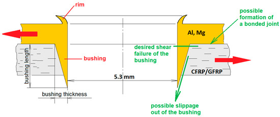
Figure 1.
Schematic representation of the expected ideal shape of the bushing. Red arrows indicate testing load.
In addition to having a suitable shape, the bushing should be sufficiently thick in the area of the planned joint failure (just below the sheet metal surface) to ensure that the resulting joint has the highest possible load-bearing capacity. It should also be sufficiently long, greater than the thickness of the composite to which it will be joined (>1.5 mm). The bushing should penetrate the composite throughout its entire thickness, and the sharp end is used to create a hem flange that closes the joint. Therefore, in the next step, metallic sheets were used to join the composite organosheets via thermal drilling, directly and sequentially (Figure 2).
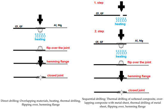
Figure 2.
Tested strategies for metal–composites joined through thermal drilling.
In sequential joining, we assume that pre-drilling the hole in the composite will help form sheet metal bushings, which may result in a better bushing shape and a sufficient thickness and length. However, this assumption needs to be verified, which is the purpose of this experiment.
2.3. Shape and Dimensions of Test Specimens
As follows, based on the selected Flowdrill tool, the dimensions of the panels for joining were determined in accordance with STN EN ISO 12996:2014 (Mechanical joining—Destructive testing of joints—Specimen dimensions and test procedure for tensile shear testing of single joints) (Figure 3).
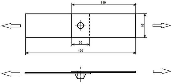
Figure 3.
Shape and dimensions of test samples and joined assembly for ∅ 5.3 mm tool. Arrows indicate testing load.
A metal sheet is placed in the upper position during joining, while a composite plate is placed in the lower position. The metal sheet is the first to come into contact with the tool, while the formed bushing penetrates the softened composite plate. The composite will not be in direct contact with the tool (in the case of direct drilling).
2.4. Methodology of Joint Creation
Joining metals and composites without breaking the fiber reinforcement is only possible if the fibers can be deflected from the joint site and flow around the bushing. This is only possible if the thermoplastic matrix is heated above its melting point, and the fibers can move when penetrated by the bushing. Although thermal drilling generates heat in the immediate vicinity, it is not sufficient to heat the composite to a certain distance from the bushing site. To maintain the continuity of the fibers, it is important to heat the composite over a specific area where the matrix will be plasticized. The fibers in the unheated zone are embedded in the matrix, while those in the softened zone are relatively free (there is only friction between the fiber and the matrix and between the fibers themselves). The plasticized zone must be large enough so that the tensile stress does not break the fibers when they are deflected from their original position, i.e., it does not exceed the maximum fiber elongation, εB. Each of the two types of fibers used can withstand a different degree of εB before breaking (see Table 2, composite with GF εB = 3.9% and composite with CF εB = 1.3%), which must also correspond to the diameter of the plasticized zone, dPZ, around the hole.
The methodology for calculating the diameter of the plasticized zone was elaborated in detail by Seidlitz et al. [30]. According to this methodology, the average dPZ must be sufficiently large so that Equation (1) applies to the average drilling tool diameter, dFD, and the type of fiber used with a known maximum εB (Figure 4).
where y is the deviation of the fibers in the joint; this is a number from the interval 0 ≤ y ≤ dFD/2.
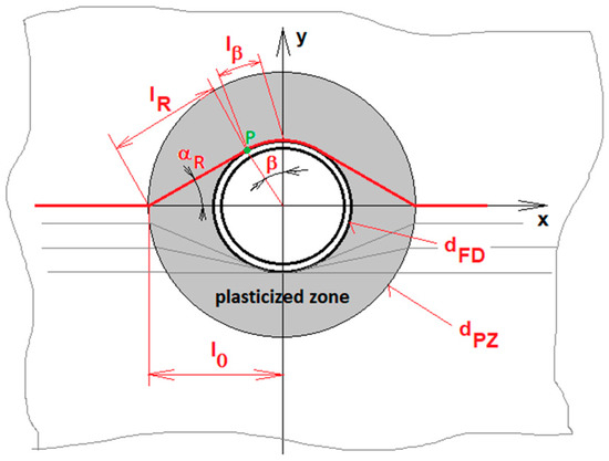
Figure 4.
Geometric model of a composite panel with unidirectionally laid fibers, adapted from [30]. dPZ—diameter of plasticized zone; dFD—diameter of Flowdrill tool; l0—length of the non-stressed fiber; lR—length of deflected fiber to point P; lβ—length of the wrapped fiber; αR—fiber deflection angle; β—angle of fiber wrapping.
Based on this equation, the minimum required diameter of the heated (plasticized) zone was determined to be dPZ = 19 mm for glass fiber composites and dPZ = 33 mm for carbon fiber composites.
2.5. Methodology for Evaluating the Shape of the Bushing
On perpendicular metallographic sections, we assessed the shape of the resulting bushings when drilling the metal sheets, creating metal–composite joints via direct and sequential drilling under the tested process parameters. Metallography sections were prepared using the standard metallography procedure: mounting to acrylic resin, grinding (#180, #500, #800, #1000, #1200), and polishing (OP/S NonDry 0.25 μm polishing suspension). Prepared sections were documented using an Olympus BXFM light microscope (Olympus, Tokyo, Japan). For all material combinations and process parameters tested, five metallographic sections were created. Bushing length and thickness were measured on all five metallographic sections, and average values are noted in Section 3.3. The perpendicular section of the bushing profile obtained from metallography was then used to calculate the volume of the bushing and determine its thickness and length for individual parameters and drilling strategies.
2.6. Methodology for Bushing Hardness Measurement
The effect of the process parameters on the material properties (strain hardening/softening) in the bushing area was determined by measuring the microhardness of the metallographic sections using a Shimadzu HMV2 hardness tester (Shimadzu, Kyoto, Japan). The test load used was 0.1 kg with a dwell time of 30 s (HV 0.3/30). The measuring pattern is shown in Figure 5. For each rotation speed and feed rate value, 5 indentations were created in the bushing area. Indentation spacing was set according to EN ISO 6507-1:2023. The minimum distances for measuring the hardness of non-ferrous metals (where d means average diagonal) are aligned with this standard, namely, the distance, 6·d, between the indentations and 3·d from the edge of the bushing. Hardness measurements were performed on the tapered edge of the bushings as low as possible while maintaining the minimum required distances from their edge.

Figure 5.
Hardness measurement points (from 1 to 5) on bushings (Al, 4800 min−1, F).
2.7. Methodology for Fiber Failure Monitoring Using Computed Tomography
Fiber continuity in organosheets near the hole was scanned using CT, Carl Zeiss Metrotom 1500 Gen1 (Carl Zeiss Industrielle Messtechnik GmbH, Oberkochen, Germany). The scanning parameters were as follows: voltage, 100 kV; current, 230 µA; integration time, 1000 ms; resolution, 27.04 µm; no filter applied.
3. Results
3.1. Metallographic Study of Bushing Formation—Drilling Al and Mg Sheet Metals
Table 3 shows metallographic sections through the bushing axis produced under the specified process parameters.
Table 3.
Metal bushings formed by metal sheet thermal drilling.
Table 3 shows that at a speed of 2400 min−1 and both feed rates, as well as at higher speeds of 4800 min−1 and a slow feed rate, discontinuous, fragmented, and (therefore) unsatisfactory bushings were produced for the Al alloy. At a speed of 4800 min−1 and a fast feed rate, a partially satisfactory bushing shape was achieved.
Compared with the Al alloy, the Mg alloy was twice as thick and thus had more material available to form the bushing at the point where the hole was created. The resulting bushings were intact for all tested process parameters, and a satisfactory bushing cross-section shape in terms of geometry was achieved at higher speeds (4800 min−1).
The prepared metallographic sections were also used to measure the hardness of the material in the bushing area and to compare it with the hardness of the original material, providing information on the possible phase transformations of the material or deformation strengthening/softening processes during thermal drilling.
Figure 5 shows an example of a metallographic section through the axis of bushings in an Al sheet with the hardness measurement points marked. The individual indentations were made at the point of greatest material deformation so that the minimum required distance from the edge of the material was maintained.
Table 4 shows the results of the Al and Mg hardness measurements at different thermal drilling parameters as an average of five measurements.
Table 4.
Average hardness values, HV 0.1, of Al and Mg bushings for process parameters tested.
Determined as the average of five measurements, the hardness values of the materials in an undeformed state (outside the drilling area) are as follows: Al—115 HV0.1 and Mg—67 HV0.1. The results show that in the case of Al, the precipitation-hardened alloy was softened by 36–42 HV units due to the process parameters and the heat generated. Increased temperature in the drilling area led to the overaging or even dissolution of the precipitates formed by age hardening. Only in the case of 2400S was there a slight strain-hardening in the alloy by 24 HV units. This is because the lower speed and feed rate did not generate enough heat to initiate softening. In the case of the Mg alloy, a slight strain-hardening in the bushing area was recorded at 2–10 HV units. This is because Mg alloys with HCP lattices have few slip planes and, therefore, a relatively small strain-hardening coefficient. After thermal drilling, both materials produce a bushing with very similar hardness (69–79 HV) regardless of the initial hardness and process parameters used.
This metallographic study of thermal drilling of metal sheets provides a basic idea of the behavior of the metal materials used when drilled separately. In this case, the bushing is formed freely, without interaction with another body.
However, when joining these sheets with polymer composites, their behavior is likely to change because the bushing will simultaneously penetrate the fiber reinforcement of the softened composite, which will resist it (CF—seven layers of fiber reinforcement; GF—three layers of fiber reinforcement). Therefore, the next step in the investigation was to create joints with polymer composites through direct drilling (according to the methodology described in Section 2.2).
3.2. Metallographic Study of Bushing Forming During the Creation of Joints by Direct Drilling
This phase of the experiment involved monitoring the formation of bushing while penetrating the softened composite. Thermal drilling was performed through two overlapping materials—metal in the upper position and a composite in the lower position (Figure 2). A different bushing shape is expected than when drilling metal alone because the composite resists the penetration of the bushing and slows down its shaping.
Table 5 shows metallographic sections of the metal–composite joints created by direct drilling, showing only the bushing formed simultaneously with the composite in a one-tool pass.
Table 5.
Metal bushings formed when metal–composite joining is achieved through direct thermal drilling.
Direct drilling improved the geometry of the Al bushings. When we separately drilled the Al sheet (Table 3), the bushings were not continuous (petals were formed) or were short with blunt ends; however, the resistance of the composite had a positive effect, helping to form Al bushings with more suitable geometry—both greater length and sharper ends. In the case of Mg alloys, the bushings were continuous, with sharp ends, but with a noticeably shorter length and greater external conicity compared with the separate drilling of the Mg alloy. However, these are only simple observations. To accurately determine the characteristics of the bushings, their thicknesses and lengths had to be measured depending on the drilling process parameters and the type of composite.
3.3. Metallographic Study of Bushing Forming During the Creation of Joints Through Sequential Drilling
As an alternative, sequential drilling was also implemented. In sequential drilling, the composite is inserted into the fixture and preheated, a hole is made in it with a flow drill tool, the composite is covered with a metal sheet (Al, Mg), and the same tool is used to make a hole and a bushing in the metal sheet, creating an interference connection with the composite. Since a pre-drilled hole in a composite could mean less resistance when forming metal bushings, the joints (bushings) created may have a more suitable geometry. We also assume that the composite is less delaminated. Table 6 shows metallographic sections of bushings in Al and Mg created under various parameters through sequential thermal drilling.
Table 6.
Metal bushings formed through metal–composite joining via sequential thermal drilling.
The shape of the bushings created by direct and sequential joining is visually very similar. To more precisely identify the influence of the process parameters and joining strategy on the geometry of the bushings, their basic characteristics, thickness and length, were determined (Table 7). In addition, the geometric shape of the bushings was also assessed, as in many cases, the length and thickness of the bushing may be satisfactory, but the end will not be sharp, or it will be otherwise geometrically unsuitable. Therefore, a color highlight was added to Table 7 to indicate whether the shape of the bushing was suitable or not.
Table 7.
Geometric characteristics of the bushings (T—thickness; L—length) when drilling metals through direct and sequential joining [31].
Figure 6 summarizes the geometric characteristics of the bushings created through separate metal drilling and the bushings in the metal–composite joints created through direct and sequential drilling for individual metals and composites.
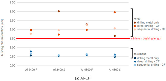
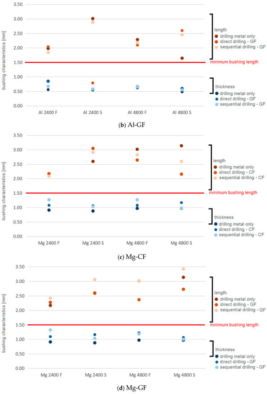
Figure 6.
Summary of the bushing characteristics for individual parameters and drilling strategies [31].
The following conclusions can be drawn from the figures above:
- The thickness of the bushings is not significantly affected by the process parameters of thermal drilling.
- Greater bushing thickness is achieved with Mg alloy (0.89–1.33 mm) because of the greater material availability in the bushing area given a sheet thickness of 2 mm.
- For Al alloys, the thickness of the bushings ranges from 0.49 to 0.86 mm, which corresponds to a smaller sheet thickness compared with Mg.
- Except for Al 2400 S–GF (Figure 6b), the lengths of the bushings for both Al and Mg were greater than the thickness of the composite, i.e., satisfactory.
- The length of the bushings is more sensitive to changes in the process parameters of thermal drilling, with the feed rate more significantly impacting the length than the rotational speed. The effect of the feed rate on the length of the bushings is clear—a slower feed rate (especially combined with higher speeds) forms longer bushings, both for Al and Mg.
- The length of the bushings was around 2 mm for Al-CF, between 2 and 3 mm for Al-GF, between 2 and 3 mm for Mg-CF, and between 2.5 and 3.5 mm for Mg-GF. This is due to the less dense weave of the GF fiber mat, thicker fibers, and fewer layers of glass fibers in GF than in CF. As a result, glass fibers have less resistance to bushing penetration.
Metallographic sections were also used to determine other 3D characteristics of the bushings. We were particularly interested in the volume of the individual bushings, as thermal drilling displaces a large volume, V, of material from its original location in the sheet metal plane, both in the direction of drilling (creating a bushing with volume V1) and opposite to the direction of drilling (creating a rim with volume V2) (Figure 7). This demonstrates under what process parameters the maximum amount of material is displaced into the bushing area.
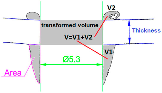
Figure 7.
Material displacement during thermal drilling.
The large volume of material transferred to the bushing area suggests that the bushing will be massive (thick) and sufficiently long to ensure the creation of a joint with the relevant load-bearing capacity.
3.4. Calculation of Bushing Volume
With some simplification, each metallographic section of the bushings can be considered a polygon (multilateral shape). The formula for calculating the Gaussian area was used to calculate the area, A, of a simple polygon. This is a mathematical algorithm for determining the area of a simple polygon whose vertices are described by Cartesian coordinates xi and yi in a plane, and it is positively oriented (the sequence of polygon vertices is counterclockwise). It is possible to use the trapezoidal method (Figure 8a), where the sequence of oriented trapezoids is calculated, and whose vertices are Pi, Pi+1; the remaining two vertices are projections of points Pi and Pi+1 on the x-axis of the coordinate system. Alternatively, the triangular method can be used (Figure 8b), where a sequence of oriented triangles with vertices 0PiPi+1 is counted. Other methods that decompose the original polygon into elementary geometric shapes can also be employed.
Figure 8.
Principle of calculating the area, A, of a polygon: (a) trapezoidal method; (b) triangular method. The colors of the sides of the polygons indicate which area of the trapezoid or triangle is positive (green) or negative (red).
The A of a polygon can be mathematically expressed as the sum of the areas of the oriented trapezoids as follows in Equation (2):
Equation (3) specifies the five-vertex polygon from Figure 8a:
After simplification, we get (Equation (4)):
The trapezoidal method was used to determine the A of the bushing cross-section created by thermal drilling under the selected process parameters. The cross-sectional A of the bushing was divided into trapezoids P1, P2, …Pi, Pi+1, …Pn, with known coordinates of vertices xi and yi (Figure 9).
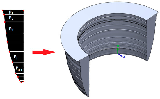
Figure 9.
Procedure for calculating the volume of the bushing.
Subsequently, the cross-multiplication of the coordinates and their summary were used to calculate the cross-sectional areas of the individual bushings.
In the next step, the second Pappus–Guldin theorem was used to calculate the volume of the bushings. This theorem calculates the volume, V, of a solid rotational body created by rotating a flat shape, F, around an external axis. According to this theorem, V is equal to the product of the A of shape F and the distance, d, traveled by the geometric center (center of gravity) of shape F during rotation. This means (5):
When applying Equation (5) to calculate the bushing created by rotating the cross-section around the axis of the hole, we can write (6)
where rT is the radius of the center of gravity of the bushing cut.
Since the cross-sections of all bushings can be simplified as triangles, we can assume that the center of gravity lies in one-third of the bushing thickness. The rotation radius of the center of gravity will thus be equal to (7) (Figure 10):
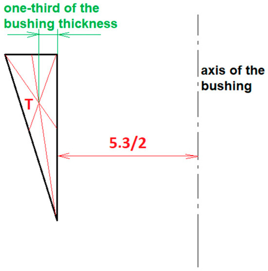
Figure 10.
Determining the rotation radius of the center of gravity (T) of the bushing cut.
The drilled volume of the 1 mm thick Al sheet and the 2 mm thick Mg sheet, i.e., the volume of the cylinder transformed into a bushing during thermal drilling with a 5.3 mm diameter tool, is equal to (8) and (9)
Table 8 shows the results of calculating the volume of the bushings in absolute values and percentages for the drilled metal sheets, as well as for the creation of joints with composites (CF and GF) via direct and sequential drilling.
Table 8.
Volume of material in mm3 and percentage of material displaced during thermal drilling from the sheet metal plane to the bushing area (red values indicate bushing fragmentation).
In some cases, the volume of the bushings was greater than the volume of the material from which they were made (values > 100% marked in color). This may mean that some parts of the circumference of such a bushing cannot be filled with material—they must contain empty spaces (petals); therefore, the bushing is fragmented, not solid. This phenomenon was also visually observed while drilling the Al alloy. In the case of the Mg sheet metal, no bushing fragmentation occurred either in the calculations or in the observations of real bushings during the experimental work.
Figure 11 illustrates the values from Table 8, supplemented with color information identical to that of Table 7. This also indicates the suitability of the resulting geometric shape of the bushing (suitable/unsuitable shape). The left columns show the values for a slow feed rate (S), and the right columns show the values for a fast feed rate (F).
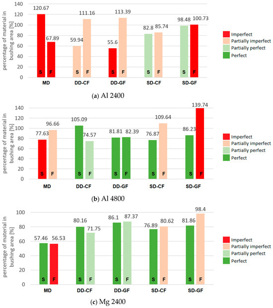
Figure 11.
Percentage of material transferred from the sheet metal plane to the bushing area during thermal drilling. MD—metal drilling; DD—direct drilling; SD—sequential drilling. Left columns—slow feed, S; right columns—fast feed, F. The color indicates whether the shape of the bushing is perfect/imperfect.
These figures show that a fast feed rate (right columns) when drilling Al sheet metal led to a greater displacement of material into the bushing area compared with a slow feed rate (left columns), albeit at the expense of the integrity of the bushing—that is, bushing fragmentation occurred (petals). Sequential drilling slightly increased the volume of the bushings compared with directly drilling Al. When joining Al and CF, a smaller proportion of material was displaced than when joining Al and GF, as CF offers greater resistance to drilling due to the larger number of fibers, denser weave, and greater number of layers in the composite organosheet. In terms of rotational speed, bushings with a more suitable geometric shape were produced at a faster rotational speed (4800 min−1).
The thickness and length measurements of the bushings (Table 7) show that the Mg alloy sheet metal did not react as sensitively to changes in process parameters during drilling. In most cases, a fast feed rate (right columns) resulted in larger bushings than with a slow feed rate (left columns), but the differences were small. Sequential drilling of the Mg sheet did not result in a significant change compared with direct drilling. When joining Mg and CF, a smaller proportion of material was displaced into the bushing area compared with joining Mg and GF, as CF offers greater resistance during drilling due to the larger number of fibers, denser weave, and greater number of layers in the composite organosheet. In terms of rotational speed, bushings with a more suitable geometric shape were produced at a faster speed (4800 min−1).
By examining bushings made under various process parameters in terms of their geometry—length, thickness, volume, and shape suitability—the following thermal drilling parameters for metal–composite joining can be recommended:
Rotational speed: 4800 min−1; Feed rate: 60 mm·min−1; Drilling strategy: Sequential drilling; Joint finishing: Hemming flange.
Cross-sections of flanged joints made under the recommended process parameters are shown in Table 9.
Table 9.
Cross-sections of final flanged metal–composite joints.
These cross-sections show that hemming the joints significantly reduces composite delamination. The hem flange locks the joint, the reinforcing fibers of the composite are enclosed under the hem flange, and the fiber-rich zone under the hem is visible, indicating the displacement of fibers during thermal drilling (Figure 12).
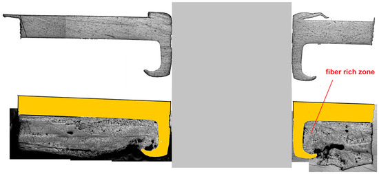
Figure 12.
Fiber-rich zone around a bushing (Al-GF 4800 S joint).
A metallographic study of the joints shows that the inner surface of the metal bushing is cylindrical, while the outer surface is conical, with Mg bushings having greater conicity. When joints created in this way are subjected to tensile shear test, the loading force, F, on the conical surface at the contact point between the bushing and the composite will decompose into a normal component, Fn, and a tangential component, Ft (Figure 13). Fn can deform the bushing, and Ft can cause the joint to open; the composite may slide along the conical bushing away from the metal sheet, pressing on the flange, and the load-bearing capacity of the joint will depend on the load-bearing capacity of the flange instead of the load-bearing part of the bushing. However, the flange is much thinner than the load-bearing part of the bushing, especially in the case of Mg; therefore, we expect that the joints will have a lower load-bearing capacity.
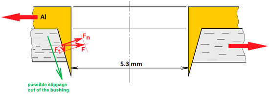
Figure 13.
Breakdown of forces acting between the composite and the bushing under tensile shear test (F—joint load; Fn—normal component of F; Ft—tangential component of F). Red arrows indicate testing load.
Therefore, we propose modifying the geometry of the bushing to the Ft of load F. This proposal is the subject of a follow-up article (Part 2) currently being prepared by the authors.
3.5. Fiber Continuity Analysis Using CT (Computed Tomography)
The GF and CF composites are manufactured by consolidating several individual layers of prepreg, in which glass and carbon fiber cloth (Twill 2/2) are used. The prepregs are then stacked on top of each other and pressed (consolidated) in a specific number of layers to obtain the desired thickness. GF consists of three layers and CF of seven. To visualize the course of the fibers in the polypropylene matrix around the hole created during sequential drilling, CT scans of individual composites were performed (Figure 14, Figure 15, Figure 16 and Figure 17).
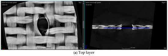
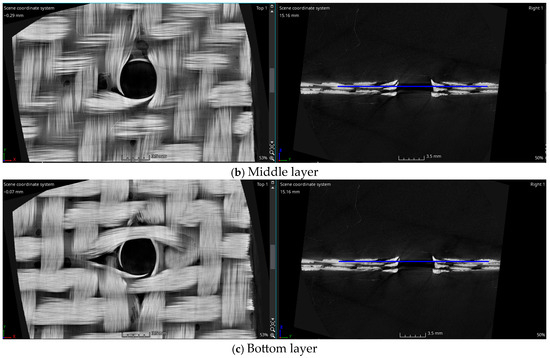
Figure 14.
CT scan of GF composite in individual layers.
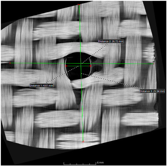
Figure 15.
The diameter of the hole in the GF and the range of fiber displacement around the hole.
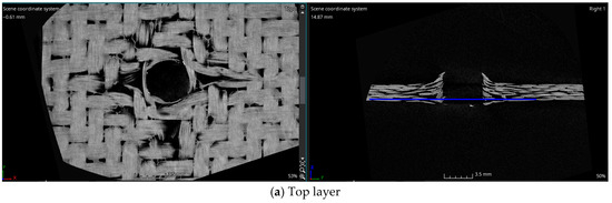
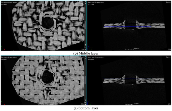
Figure 16.
CT scan of CF composite in individual layers.
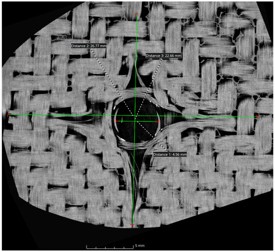
Figure 17.
The diameter of the hole in the CF and the range of fiber displacement around the hole.
Figure 14 shows the deflection of fibers around the hole in individual layers. No damage to the fibers is visible, but slight delamination around the hole can be seen (images on the right).
Figure 15 shows the diameter of the resulting hole and the distance from the axis at which the fibers are deflected from their original position.
Figure 15 shows that when drilling a preheated GF composite, the tension in the fibers caused them to partially return, resulting in a hole diameter of 4.61 mm. This is only slightly enlarged in the second step of sequential drilling. The diameter at which the fibers are deflected from their original position is approximately 26 mm.
For the CF composite, Figure 16 shows the situation in the top, middle, and bottom layers.
Figure 16 shows the deflection of fibers around the hole in individual layers; no damage to the fibers is visible, but the delamination of fibers around the hole (images on the right) is more extensive than it was with GF.
Figure 17 shows the diameter of the resulting hole and the diameter at which the fibers are deflected from their original position.
As in the case of GF, Figure 17 shows that when drilling preheated composite, the tension in the fibers causes them to partially retract, resulting in a hole with a diameter of 4.56 mm. The diameter at which the fibers are deflected from their original position is also approximately 26 mm.
An overview of the results follows:
- -
- Separately drilling an Al sheet metal under certain process parameters results in discontinuous, often fragmented bushings with unsuitable geometry. If a bushing is formed on another supporting material—which was a composite part in this case—it will not have a sufficient size or suitable shape. Suitable thermal drilling parameters for joining purposes require higher speeds and slower feed rates.
- -
- Due to its greater thickness, Mg sheets have a larger available material volume for forming bushings and are less sensitive to process parameters or drilling strategy. However, the resulting shape has greater conicity, and composite sliding may occur in the joint along this steep conical surface. In any case, with Mg material, higher speeds and slower feed rates have a clear positive effect on the resulting shape of the bushing when drilling Mg sheet metal separately. Direct and sequential joining with the composite resulted in shorter and thicker bushings, which is a consequence of slowing the bushing-forming process caused by the composite.
- -
- During thermal drilling, changes in material behavior were observed: the precipitation-hardened Al alloy was softened in the deformed volume, while the Mg alloy underwent slight strain-hardening in the bushing area. The resulting hardness of both materials in the bushing area was very similar—approx. 70–79 HV0.1.
- -
- By assessing the thickness and length of individual bushings, as well as the volume of sheet material displaced into the bushing area, it is possible to recommend higher speeds (4800 min−1), lower feed rates (60 mm·min−1), and a sequential drilling strategy. However, this means more operational steps, which can increase the production time of the joint.
- -
- The achieved length allows the joint to be closed with a hem flange, which limits the delamination of the composite on the reverse side of the joint. Composite delamination is a typical failure mode in layered laminates manufactured using prepreg consolidation.
- -
- CT scans visualized the course of the fibers in individual layers and their deflection around the opening, confirming their continuity without signs of damage. Heating the composite above the melting temperature of the polymer matrix—carried out over an area larger than the calculated diameter of the plasticized zone—allowed the fibers to deflect when the tool penetrated the opening, causing them to stretch and elongate less than their critical elongation at break.
4. Conclusions
These findings show that it is possible to adapt thermal drilling technology to join metals and composite fiber plates without disrupting the continuity of the reinforcing fibers by applying suitable process parameters and simultaneously heating the joined pair. Heating the composite plate to melt the polypropylene matrix suggests that, in addition to the mechanical connection of the two materials via the bushing, an adhesive bond may also occur across the entire overlapped area. This would create a hybrid joint with higher energy absorption upon failure, which is suitable for applications in the automotive industry. Verification of these assumptions, determination of the load-bearing capacity of joints created in this way, and a proposal for a possible modification of the joint geometry to limit the composite sliding off from the bushing will be the subject of another article—Part 2.
Author Contributions
Conceptualization, A.G.; methodology, A.G. and D.D.; validation, M.F.; formal analysis, A.G.; investigation, A.G. and D.D.; data curation, T.T.; writing—original draft preparation, A.G.; writing—review and editing, A.G. and D.D.; visualization, A.G. and T.T.; project administration, A.G.; funding acquisition, A.G. All authors have read and agreed to the published version of the manuscript.
Funding
This research was funded by the Scientific Grant Agency of the Ministry of Education, Research, Development, and Youth of the Slovak Republic under project VEGA 1/0229/23: Research on the applicability of thermal drilling technology for the creation of multi-material joints in the automotive industry.
Data Availability Statement
The original contributions presented in the study are included in the article, further inquiries can be directed to the corresponding author.
Conflicts of Interest
The authors declare no conflicts of interest.
References
- Dong, K.; Kong, J.; Peng, Y.; Zhou, Q.; Wang, K. A new strategy for high-strength joining of dissimilar materials. J. Mater. Process. Tech. 2020, 283, 116724. [Google Scholar] [CrossRef]
- Fang, X.; Zhang, F. Hybrid joining of a modular multi-material body-in-white structure. J. Mater. Process. Tech. 2020, 275, 116351. [Google Scholar] [CrossRef]
- Kaspar, J.; Choudry, S.A.; Vielhaber, M. Concurrent Selection of Material and Joining Technology–Holistically Relevant Aspects and Its Mutual Interrelations in Lightweight Engineering. Procedia CIRP 2018, 72, 780–785. [Google Scholar] [CrossRef]
- Kaspar, J.; Revfi, S.; Albers, A.; Vielhaber, M. Cross-Component Material and Joining Selection for Functional Lightweight Design based on the Extended Target Weighing Approach—A Detailed Application Example. Procedia CIRP 2019, 84, 694–700. [Google Scholar] [CrossRef]
- Kaspar, J.; Choudry, S.A.; Vielhaber, M. Systemic Assessment and Selection of Material and Joining Technology Exemplarily Applied on the Automotive Bodywork. Procedia CIRP 2020, 91, 201–206. [Google Scholar] [CrossRef]
- Zhang, X.; Chen, C. Experimental investigation of joining aluminum alloy sheets by stepped mechanical clinching. J. Mater. Res. Technol. 2022, 19, 566–577. [Google Scholar] [CrossRef]
- Drossel, W.G.; Riemer, M.; Scholz, P.; Osiecki, T.; Kroll, L.; Frankiewicz, M.; Skomudek, W. Forming induced interface structures for manufacturing hybrid metal composites. CIRP Ann.-Manuf. Technol. 2020, 69, 253–256. [Google Scholar] [CrossRef]
- Klein, F.; Litnovsky, A.; Tan, X.; Gonzalez-Julian, J.; Rasinski, M.; Linsmeier, C.; Bram, M.; Coenen, J.W. Smart alloys as armor material for DEMO: Overview of properties and joining to structural materials. Fusion Eng. Des. 2021, 166, 112272. [Google Scholar] [CrossRef]
- Balakrishnan, V.S.; Hart-Rawung, T.; Buhl, J.; Seidlitz, H.; Bambach, M. Impact and damage behaviour of FRP-metal hybrid laminates made by the reinforcement of glass fibers on 22MnB5 metal surface. Compos. Sci. Technol. 2020, 187, 107949. [Google Scholar] [CrossRef]
- Jeevi, G.; Nayak, S.K.; Abdul Kader, M. Review on adhesive joints and their application in hybrid composite structures. J. Adhes. Sci. Technol. 2019, 33, 1497–1520. [Google Scholar] [CrossRef]
- Göring, M.; Schreiter, K.; Schuberth, A.; Windberg, T.; Jung, H.; Anders, S.; Müller, P.; Nickel, D.; Nestler, D.; Kroll, L.; et al. Amino Group Bearing Organic–Inorganic Hybrid Materials for Joining Aluminum Alloys and Thermoplastic Fiber-Reinforced Parts. Adv. Mater. Interfaces 2017, 4, 1601115. [Google Scholar] [CrossRef]
- Kraus, M.; Merklein, M. Potential of Joining Dissimilar Materials by Cold Formed Pin-Structures. J. Mater. Process. Tech. 2020, 283, 116697. [Google Scholar] [CrossRef]
- Vorderbrüggen, J.; Köhler, D.; Grüber, B.; Troschitz, J.; Gude, M.; Meschut, G. Development of a rivet geometry for solid self-piercing riveting of thermally loaded CFRP-metal joints in automotive construction. Compos. Struct. 2022, 291, 115583. [Google Scholar] [CrossRef]
- Gröger, B.; Römisch, D.; Kraus, M.; Troschitz, J.; Füßel, R.; Merklein, M.; Gude, M. Warmforming Flow Pressing Characteristics of Continuous Fibre Reinforced Thermoplastic Composites. Polymers 2022, 14, 5039. [Google Scholar] [CrossRef]
- Gröger, B.; Köhler, D.; Vorderbrüggen, J.; Troschitz, J.; Kupfer, R.; Meschut, G.; Gude, M. Computed tomography investigation of the material structure in clinch joints in aluminium fibre-reinforced thermoplastic sheets. Prod. Eng. 2022, 16, 203–212. [Google Scholar] [CrossRef]
- Presse, J.; Künkler, B.; Michler, T. Enhancements of a Stress-Based Approach for Fatigue Life Estimation of Multi-Material Connections Joined by Self-Piercing Rivets and Adhesive. Procedia Struct. Integr. 2019, 19, 423–432. [Google Scholar] [CrossRef]
- Wang, X.; Ji, Z.; Zheng, C.; Liu, R. Joining similar and dissimilar material combinations by laser shock forming. J. Manuf. Process. 2020, 60, 318–327. [Google Scholar] [CrossRef]
- Vorderbrüggen, J.; Meschut, G. Investigations on a material-specific joining technology for CFRP hybrid joints along the automotive process chain. Compos. Struct. 2019, 230, 111533. [Google Scholar] [CrossRef]
- Meschut, G.; Merklein, M.; Brosius, A.; Drummer, D.; Fratini, L.; Füssel, U.; Gude, M.; Homberg, W.; Martins, P.; Bobbert, M.; et al. Review on mechanical joining by plastic deformation. J. Adv. Join. Process. 2022, 5, 100113. [Google Scholar] [CrossRef]
- Han, D.; Yang, K.; Meschut, G. Mechanical joining of glass fibre reinforced polymer (GFRP) through an innovative solid self-piercing rivet. J. Mater. Process. Tech. 2021, 296, 117182. [Google Scholar] [CrossRef]
- Troschitz, J.; Vorderbrüggen, J.; Kupfer, R.; Gude, M.; Meschut, G. Joining of Thermoplastic Composites with Metals Using Resistance Element Welding. Appl. Sci. 2020, 10, 7251. [Google Scholar] [CrossRef]
- Troschitz, J.; Füßel, R.; Kupfer, R.; Gude, M. Damage Analysis of Thermoplastic Composites with Embedded Metal Inserts Using In Situ Computed Tomography. J. Compos. Sci. 2022, 6, 287. [Google Scholar] [CrossRef]
- Köhler, D.; Popp, J.; Kupfer, R.; Troschitz, J.; Drummer, D.; Gude, M. In-Situ Computed Tomography—Analysis of a Single-Lap Shear Test with Composite-Metal Pin Joints. J. Phys. Conf. Ser. 2023, 2526, 012067. [Google Scholar] [CrossRef]
- Grothe, R.; Weck, D.; Sennewald, C.; Troschitz, J.; Gude, M.; Cherif, C. Joining of Composites with Metals using Graded Metal Fabric Interfaces. J. Phys. Conf. Ser. 2023, 2526, 012045. [Google Scholar] [CrossRef]
- Winhard, J.; Nestler, D.; Kroll, L. Effects of Process Parameters in Thermoforming of Unidirectional Fibre-Reinforced Thermoplastics. Polymers 2024, 16, 221. [Google Scholar] [CrossRef] [PubMed]
- Lim, G.H.; Heidari-Rarani, M.; Bodjona, K.; Raju, K.P.; Romanov, V.; Lessard, L. Mechanical characterization of a flexible epoxy adhesive for the design of hybrid bonded-bolted joints. Polym. Test. 2019, 79, 106048. [Google Scholar] [CrossRef]
- Presse, J.; Künkler, B.; Michler, T. Stress-based approach for fatigue life calculation of multi-material connections hybrid joined by self-piercing rivets and adhesive. Thin–Walled Struct. 2021, 159, 107192. [Google Scholar] [CrossRef]
- Kim, J.H.; Wang, L.S.; Putta, K.; Haghighi, P.; Shah, J.J.; Edwards, P. Knowledge based design advisory system for multi-material joining. J. Manuf. Syst. 2019, 52, 253–263. [Google Scholar] [CrossRef]
- Gerstenberger, C.; Osiecki, T.; Timmel, T.; Kroll, L. Influence of cathodic dip painting on the mechanical strength of material-adapted composite/metal joints. Polimery 2018, 63, 750–754. [Google Scholar] [CrossRef]
- Seidlitz, H.; Ulke-Winter, L.; Kroll, L. New Joining Technology for Optimized Metal/Composite Assemblies. J. Eng. 2014, 2014, 958501. [Google Scholar] [CrossRef]
- Guzanová, A.; Veligotskyi, N. Effect of thermal drilling strategy on the geometrical characteristics of metal–composite joints. Innovations 2025, 13, 44–47. [Google Scholar]


Disclaimer/Publisher’s Note: The statements, opinions and data contained in all publications are solely those of the individual author(s) and contributor(s) and not of MDPI and/or the editor(s). MDPI and/or the editor(s) disclaim responsibility for any injury to people or property resulting from any ideas, methods, instructions or products referred to in the content. |
© 2025 by the authors. Licensee MDPI, Basel, Switzerland. This article is an open access article distributed under the terms and conditions of the Creative Commons Attribution (CC BY) license.