Abstract
As a kind of novel binderless composite, WC-cBN-SiCw composite possesses significant potential value in special sealing components and high-pressure medium nozzles. However, under severe wear and corrosion conditions, the surface defects caused by friction will be accelerated to become a crack source in aggressive environments. Because of the intrinsic brittleness of WC cemented carbide, its strength is extremely sensitive to local surface damage. Therefore, the influence of applied load (10 N, 20 N, 40 N and 60 N) on its tribological behavior was studied. Meanwhile, the impact of corrosion resistance of WC-cBN-SiCw composite on surface damage induced by friction was further investigated.
1. Introduction
Cemented carbide is a highly significant hard material due to its exceptional hardness, mechanical strength, and remarkable resistance to abrasion. It has been widely utilized in steel rolling, the automotive industry, cutting tools, the aerospace sector, and rock drilling [1,2,3,4]. The primary composition of cemented carbide comprises refractory metal carbides (WC, TaC, TiC) and metal bonding phases (Co, Ni, Mo). Among these compositions, WC-Co represents the most representative conventional cemented carbide system that relies on Co’s excellent wettability for the WC phase during the sintering process. The dissolution and re-precipitation reaction of WC into the Co binder promote sintering while enhancing mechanical properties such as fracture toughness and strength [5]. However, the presence of the Co binder compromises the hardness, wear resistance, and corrosion resistance of cemented carbide. Moreover, high cost and synergistic toxicity also restrict the application scope of WC-Co cemented carbides [6,7]. Therefore, the development of high-performance binderless cemented carbides has emerged as an urgent industrial demand.
Recently, WC-ZrO2, WC-TaC, WC-Al2O3, and WC-MgO composites have been synthesized, exhibiting exceptional hardness, chemical stability, wear resistance, and corrosion resistance [8,9,10,11]. However, the application of binderless cemented carbide is limited due to brittleness and densification issues arising from the lower self-diffusion coefficient and strong covalent bond structure of WC [12], as shown in Figure 1. To address these challenges, second-phase toughening and innovative sintering methods have been employed. The primary toughening methods encompass particle dispersion toughening, whisker toughening, phase transformation toughening, and self-toughening [13]. The toughening mechanisms encompass whisker pullout, dislocation pinning, crack deflection, and crack bridging. The main toughening mechanisms for phase transformation toughening involve the generation of compressive stress and microcracking resulting from shear deformation and volumetric expansion. Previous studies have demonstrated that a single toughening method is insufficient to fully exploit the potential of toughening phases [14]. The synergistic toughening effect is typically superior to the cumulative effect of individual toughening mechanisms.
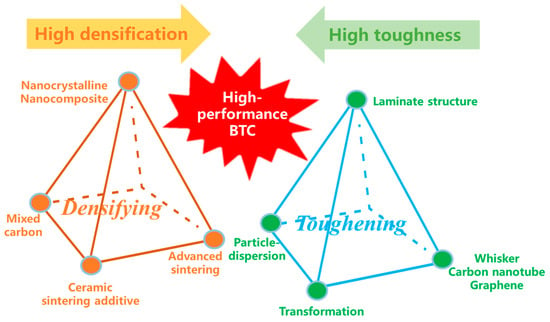
Figure 1.
The challenges in developing binderless tungsten carbide [12].
Previous studies on synergistic toughening have predominantly focused on the utilization of multi-scale or multi-morphology toughening phases. Sun et al. [15] proposed a novel macro–micro–nano multistage toughening mechanism, which demonstrated significantly enhanced toughening efficiency. The primary mechanism underlying the multi-scale toughening strategy can be attributed to a process of energy dissipation through multiple stages of fracture. WC-Co cemented carbide toughening by micro and nano CeO2 particles was demonstrated by Cai et al. [16], with the main mechanism being grain refinement. Chen et al. [17] investigated the toughening of Si3N4 ceramic composites through the synergistic incorporation of multilayer graphene (MLG) and β-Si3N4 whiskers (β-Si3N4w). Their results demonstrated that the combination of MLG and β-Si3N4w exhibited synergistic effects of pull-out, crack deflection, crack branching, and bridging. Sun et al. [18] also demonstrated the viability of utilizing low-dimensional materials (such as MLG, CNT, SiCnw) as reinforcement for high-entropy ceramics (HEC). In comparison to particle-dispersion or phase-transformation toughening, whiskers or fibers exhibit potential advantages at elevated temperatures [15]. Therefore, multi-scale and multi-morphology toughening produced synergistically by low-dimensional materials and micro/nano particles can unlock their full potential for toughness.
It is widely acknowledged that cBN exhibits superior mechanical properties compared to cemented carbide. Therefore, cBN has also been employed as a toughening phase for WC-Co cemented carbide to enhance hardness, fracture toughness, and wear resistance [19,20,21]. Wu et al. [22,23] further synthesized binderless WC-cBN composites through high-pressure synthesis. Their WC-cBN composites demonstrate exceptional hardness and fracture toughness. Meanwhile, the incorporation of cBN can also enhance grain refinement by impeding the mobility of grain boundaries [24,25]. SiC whisker (SiCw) exhibits a high aspect ratio, elastic modulus, exceptional strength, and thermal conductivity, making it an ideal toughening phase for ceramics [26,27]. Hence, a kind of novel WC-cBN-SiCw cemented carbide (named WBS for short) with a multi-scale and multi-morphology toughening strategy has been prepared, which possesses a great combination of hardness and fracture toughness [28].
Cemented carbide is frequently subjected to severe friction and wear conditions, which will lead to the rapid degradation of the material surface as well as the formation of surface defects. Meanwhile, a corrosive environment is inevitable in engineering applications of WC cemented carbide. Surface defects caused by friction will be accelerated to become a crack source in aggressive environments. Because of the intrinsic brittleness of WC cemented carbide, its strength is extremely sensitive to local surface damage [29,30]. Hence, it is important to investigate the friction and wear behavior of novel WC-cBN-SiCw hard material. Furthermore, the influence of surface damage caused by friction on its corrosion resistance is also studied. The aim of this study is to elucidate the damage mechanism of novel WC-cBN-SiCw under friction conditions, and further analyze its damage resistance in corrosive environments.
2. Materials and Methods
The starting materials used in this study included commercial WC powder (average size of 74 µm, >99.0% purity, Sinopharm Chemical Reagent Co., Ltd., Shanghai, China), cBN particles (particle sizes of 74 µm, >99.9% purity, Hebei Senyuan Metal Materials Co., Ltd., Shijiazhuang, China), and nano SiC whisker (average diameter of 50–100 nm, average length of 40–60 µm, >99.9% purity, Beijing Deke Daojin Science and Technology Co., Ltd., Beijing, China). The mass fraction of the raw materials was 10 wt.% cBN, 1 wt.% SiC whisker, and 89 wt.% WC. In order to obtain multi-scale and multi-morphology composite powder, the preparation processes of dry ball milling and wet ball milling were combined. The preparation process of WBS composite powder is shown in Figure 2.
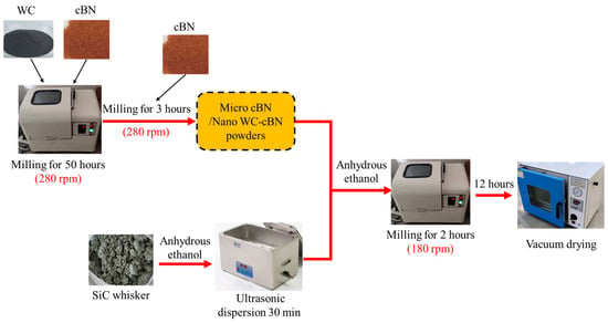
Figure 2.
The preparation process of WC-cBN-SiCw composite powder.
As shown in Figure 3, the particle size distribution of WC-cBN-SiCw composite powder possesses three peaks, which are at 160 nm, 630 nm and 2.25 µm. Meanwhile, as shown in Figure 4a,b, the morphology of SiC whisker was obtained. The nano-cBN particles were distributed on micron-scale cBN particles and SiC whiskers.
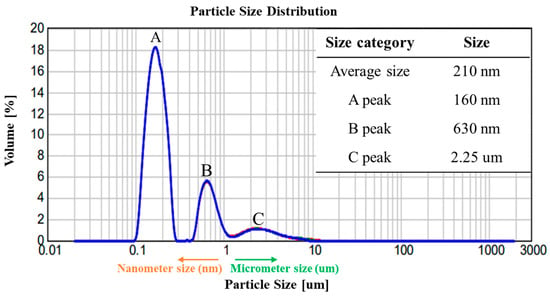
Figure 3.
The particle size distribution of WC-cBN-SiCw composite powder.
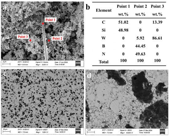
Figure 4.
The microstructure (a) and point EDS (b) of WBS composite powder; the microstructure of sintered WBS composite (c,d).
The WBS composite was sintered using Spark Plasma Sintering (SPS-20T-5-III, Shanghai Chenhua Technology Co., Ltd., Shanghai, China). The sintering parameters were as follows: the sintering temperature was set at 1300 °C, with a holding time of 5 min and a pressure of 50 MPa. The entire sintering process was conducted under high vacuum conditions (5 × 10⁻³ Pa) to ensure the specimen‘s purity. As shown in Figure 4c,d, the multi-scale characteristic can be reserved in sintered WBS composite. The Vickers hardness (HV) and fracture toughness (KIC) of the WBS composite were determined using the indentation method with a load of 30 Kgf (294.3 N) and a holding time of 15 s. The Vickers hardness and fracture toughness of WBS composite were measured to be 12.80 GPa and 10.6 MPa·m1/2, respectively [28]. The detailed mechanical property tests and toughening mechanism of WBS composites can be found in [28]. For every sample, the average hardness and fracture toughness value of ten indentations was obtained.
Here, represents the Vickers hardness value (MPa); is the applied load (N); and is the diagonal length of the indentation (mm).
Here, is fracture toughness (MPa·m1/2); is average indentation crack length (mm).
The dry sliding wear test was conducted at room temperature using a reciprocating ball-on-flat tribometer (MFT-5000, Rtec Instruments Technology Co., Ltd., San Jose, CA, USA). The experiment employed Si3N4 balls (99.9% purity) with a diameter of 4 mm to facilitate the sliding process on WBS composites. The sliding velocity was set at 0.1 m/s, while the duration of sliding was maintained for 30 min (equivalent to 180 m). The stroke length of the reciprocating motion was 5 mm, while the total number of cycles for reciprocating sliding amounted to 15,000. The applied normal loads were 10 N, 20 N, 40 N, and 60 N. The friction coefficient was directly measured by a computer and force sensor. The average friction coefficient was determined by selecting the steady-state phase of the wear test. The wear volume and wear rate were assessed by conducting a 3D abrasion test.
In order to evaluate the influence of surface damage on corrosion resistance, the specimens were polished to mirror (1 µm) and rough (74 µm) states. The electrochemical measurements were carried out in 3.5 wt.% NaCl solution to simulate seawater, using an Electrochemical Workstation (CS310M, Wuhan Corrtest Instruments Corp., Ltd., Wuhan, China). All specimens were sealed in epoxy resin with an exposure area of 1 cm2, which was used as working electrode. The Saturated Calomel Electrode (SCE) was used as reference electrode and a platinum sheet (1 cm2) was used as counter electrode. The Open Circuit Potential (OCP) was measured for 1 h. The Electrochemical Impedance Spectroscopy (EIS) values were measured at OCP with an amplitude perturbation voltage of 10 mV from 10−3 to 105 Hz. The polarization tests (Tafel curves) were obtained with the working electrode potential starting from −1 V to 1.5 V (vs. SCE reference electrode). The Tafel curves were automatically fitted by CS Analysis software (Wuhan Corrtest Instruments Corp., Ltd., Wuhan, China) to obtain the Self-corrosion Potential (Ecorr) and Self-corrosion Current Density (Icorr). X-ray Photoelectron Spectroscopy was performed (Escalab 250Xi, ThermoFisher Scientific Co., Waltham, MA, USA). The XPS data were analyzed with XPSPEAK 4.1, and standard carbon C 1s binding energy (284.8 eV) was used to calibrate the XPS peaks. The surface morphology and elemental distribution were characterized using an FE-SEM (Sigma300, Carl Zeiss AG, Oberkochen, Germany) equipped with an EDS probe.
3. Results and Discussion
3.1. Friction Behavior
The evolution of friction coefficient curves under different loads is presented in Figure 5a. The friction coefficient exhibits a running-in process, characterized by a rapid increase in the friction coefficient [31]. The friction coefficient remains essentially unchanged during the stable wear stage. The average friction coefficient under 10 N and 20 N load is determined as 0.486, as illustrated in Figure 5b. With an increase in load from 10 N to 60 N, the average friction coefficient exhibits a corresponding increase from 0.486 to 0.609. This suggests that a frictional transformation can be observed when the applied load exceeds 40 N.
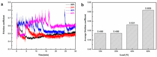
Figure 5.
Friction coefficient evolution (a) and average friction coefficient (b) under a load of 10 N, 20 N, 40 N and 60 N.
Under a load of 10 N, the friction coefficient of WBS composite decreases initially, and then exhibits a slight increase. This implies that the frictional process attained a state of stable friction within a relatively brief period (<5 min). Under a load of 20 N, the friction coefficient exhibits an initial decrease followed by a transition at 5 min. The friction coefficient decreases and reaches a stable wear stage after the transition. The frictional process under a load of 40 N exhibits an extended running-in period. The friction coefficient decreases after 13 min and reaches a stable wear stage. The frictional transition, however, reoccurs at 25 min, indicating the disruption of the stable wear stage. Under a load of 60 N, the friction coefficient exhibits a decrease after a brief running-in period. The frictional transition is also observed at the 5 min mark. However, the friction coefficient exhibits significant fluctuations subsequent to the occurrence of frictional transition. For 60 N load, the friction coefficient is significantly higher than 10 N and 20 N load. The friction coefficient reaches a stable wear stage at approximately 16 min. This indicates that achieving a stable wear stage becomes increasingly challenging under higher loads.
The wear track exhibited an increase in both depth and width with increasing load, as shown in Figure 6a,b. The wear area expanded from 5.43 mm2 to 12.75 mm2 with increasing load. Additionally, both the wear volume and wear rate increased with the growing load, as shown in Figure 6c,d. The wear volume and wear rate exhibited a significant increase as the applied load exceeded 40 N. Hence, the WBS composite shows a similar wear process under low load (10 N and 20 N). As the applied load surpassed 40 N, a noticeable shift in wear behavior was observed, which is consistent with the evolution of the friction coefficient.
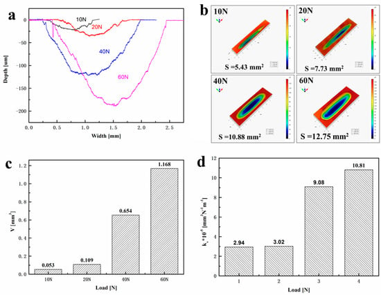
Figure 6.
Cross-sectional areas (a), 3D interferometer wear morphology (b), the wear volume V (c) and wear rate Kv (d) of WBS composite under a load of 10 N, 20 N, 40 N and 60 N.
As depicted in Figure 7a,b, the surface exhibits a substantial quantity of wear debris under a load of 10 N. The observed wear debris exhibits a loose adhesion to the surface, potentially attributable to the application of a lower load. As depicted in Figure 7c,d, under an applied load of 20 N, the wear products experience compaction with increasing load. The presence of wear debris exhibiting strong adhesion to the surface was observed. As depicted in Figure 7e,f, when subjected to a load of 40 N, obvious surface cracks can be found because of the fracture of wear products induced by higher loads. The continuous rolling motion promotes the process of their transformation from wear debris into particulate matter. The wear products undergo various processes, including formation, rolling, crushing, and fracture, during the frictional processing. This process undergoes continuous recycling, leading to the constant consumption of internal materials. As depicted in Figure 7g,h, upon increasing the load to 60 N, a more pronounced degradation of the friction layer is observed, characterized by substantial erosion and severe wear regions.
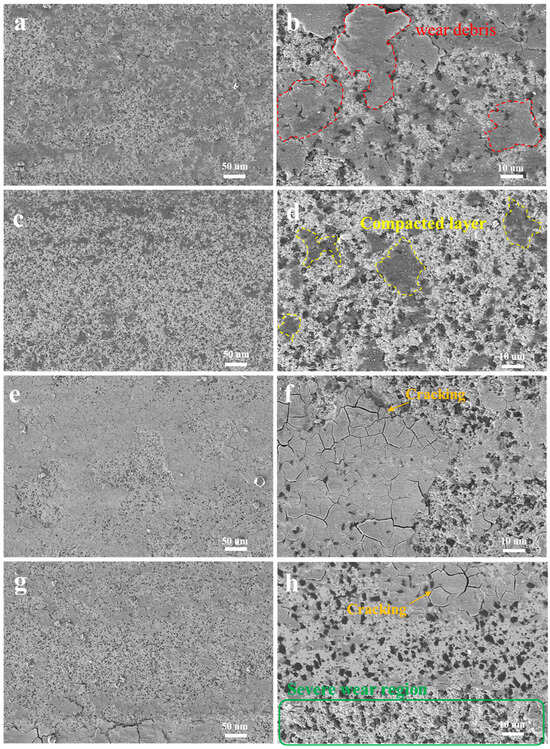
Figure 7.
The worn morphology of WBS composite under different load, (a) 10N in high-magnification; (b) 10 N in low-magnification; (c) 20 N in high-magnification; (d) 20 N in low-magnification; (e) 40 N in high-magnification; (f) 40N in low-magnification; (g) 60 N in high-magnification; (h) 60 N in low-magnification.
The wear mechanisms include abrasive wear and fatigue wear, based on the analysis of wear characteristics. At lower loads (10 N and 20 N), the WBS composite surface exhibits micro-cutting phenomena, while simultaneously experiencing the formation of micro-cracks due to stress. However, the lower load fails to meet the criteria for crack instability growth. Consequently, as a result of micro-cutting, the surface material undergoes delamination and forms a groove. The spalling surface material disintegrates into granular fragments under the influence of stress, serving as the medium for subsequent sliding abrasive wear [32]. Therefore, under low load conditions, the predominant wear mechanism is attributed to micro-cutting and micro-crack initiation, which can be classified as abrasive wear.
Under high loads (40 N and 60 N), the wear surface exhibits a distinctly disparate morphology compared with lower loads. In Figure 7f,h, it is evident that a non-continuous friction layer has developed on the surface under 40 N and 60 N loads. The surface exhibited a significant number of cracks, accompanied by the presence of distinct particles and fine abrasive particles within the friction layer. Wanget et al. [33] reported a similar situation in WC-CoCrFeNiMn composite, which was considered as fatigue wear. High loads facilitate the increase of fatigue sources, thereby promoting the initiation of surface layer cracks. When the contact stress surpasses the fracture threshold of the material, a sudden expansion of cracks occurs, leading to fatigue failure of the contacting surface. In the initial stage of friction, the applied shear force did not induce surface rupture. After a specific number of cycles, cracks develop on the surface and propagate due to contact fatigue. As shown in Figure 5a, the sudden increase of the friction coefficient corresponds to the abrupt expansion of surface cracks, leading to the initiation of fatigue fractures.
The Mapping EDS of the friction layer is depicted in Figure 8a,b. The composition of the friction layer mainly consists of W and O. The distinct demarcation of cBN particles implies the inherent stability of cBN under frictional conditions, which may be attributed to the high hardness of cBN. As the applied load increases from 20 N to 60 N, the proportion of W element rises from 66.47% to 71.26%, while the O element exhibits an increment from 8.43% to 9.77%. Conversely, there is a decrease in the percentage of C element from 6.91% to 5.53%. The alteration of elemental composition within the friction layer suggests that higher loads promote the oxidation process of WC. The contact surface undergoes oxidation and forms an oxide film during the process of friction. The formation of the oxide film may be attributed to the progressive accumulation of frictional heat. Qin et al. [8] pointed out that the oxide film can serve as an effective lubricant for WC-MgO-ZrO2 composite, thereby mitigating frictional resistance and reducing the friction coefficient. However, it should be noted that this rule is exclusively suitable to abrasive wear during the frictional process. In this study, the wear mechanism under high load conditions is fatigue wear, where the continuous fatigue cracking of the oxide film hinders its lubrication functionality.
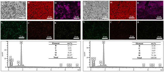
Figure 8.
The Mapping EDS of worn morphology under 20 N (a) and 60 N (b) load.
The scheme of wear mechanisms is shown in Figure 9. At lower loads, like 10 N applied load, the WBS composite surface exhibits micro-cutting phenomena, which induces spalling of WC particles. This is typical abrasive wear, which is caused by the scratching action of hard particles [34]. Consequently, as a result of micro-cutting, the surface material undergoes delamination and forms a groove. The spalling material disintegrates into granular fragments under the influence of stress, serving as the medium for subsequent sliding abrasive wear [32]. As the applied load increases to 20 N, the unconsolidated wear debris accumulates and compacts. Then, a non-continuous friction layer is formed.
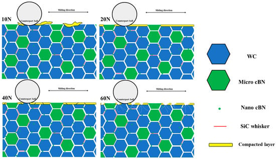
Figure 9.
The scheme of wear mechanism of WBS composite under different applied loads.
As the applied load increases to 40 N, significant cracks and fine spalling particles can be found, which is a typical fatigue wear phenomenon [33]. The high applied load promotes the initiation of fatigue sources, which induces surface cracks. When the contact stress surpasses the fracture threshold, a sudden expansion of cracks occurs, leading to fatigue failure of the contacting surface. This is the main reason for the sudden change of friction coefficient, which is the frictional transition. As the applied load increases to 60 N, severe wear can be found on local surfaces. In conclusion, the threshold of wear mechanism transformation is 40 N. As the applied load exceeds 40 N, the wear mechanism transforms from abrasive wear to fatigue wear.
3.2. Corrosion Resistance
As shown in Figure 10a, the OCP potential of WBS composite with a rough surface state decreases with exposure time in NaCl solution. Compared with the rough surface state, the WBS composite with mirror surface state possesses higher OCP potential, which means more stable behavior in NaCl solution. As shown in Figure 10b, the Tafel curves of mirror and rough surface states possess similar characteristics, which further indicates similar corrosion mechanisms for different surface states. The Ecorr and Icorr can be obtained by fitting the Tafel curve. For mirror and rough surface states, the Ecorr is basically similar. However, the WBS composite with rough surface possesses higher Icorr, which indicates a higher corrosion rate. A rough surface state increases the actual surface area, which provides more corrosion locations. Meanwhile, the pits and cracks on the rough surface can lead to localized accumulation of corrosive solution, thereby forming micro-reaction sites and subsequently promoting the expansion of pits and cracks [35]. In the anode polarized region, the pseudo-passivation characteristic can be found for both mirror and rough surfaces. Pseudo-passivation refers to the phenomenon where the current density in the anode polarization region has decreased to a certain extent, but the system has not yet reached the true passivated state. In the study of electrochemical corrosion, a phenomenon can be classified as true passivation only when the passivation current density is less than 10 μA/cm2 [36]. The current densities in the passivation zone of the WBS composites under rough and smooth conditions are 400 μA/cm2 and 530 μA/cm2, respectively, which are significantly higher than the value of 10 μA/cm2. The primary characteristic of pseudo-passivation is the incomplete dense passivation layer on the surface, which renders pseudo-passivation incapable of effectively inhibiting the progression of corrosion. The pseudo-passivation phenomenon has also been reported in H2SO4 and HCl solutions for WC-Co cemented carbide [37].
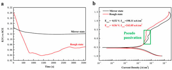
Figure 10.
OCP and Tafel curves of WBS composites with mirror and rough surface states, (a) OCP curves; (b) Tafel curves.
As shown in Figure 11a, the arc radius of the mirror surface of WBS composite is obviously larger than that of the rough surface. The larger arc radius of capacitive reactance indicates that WBS composites with mirror surface state have larger charge transfer resistance in NaCl solution, which means a lower corrosion rate. As shown in Figure 11b,d, the impedance of the mirror surface is measured to be 1776.3 Ω·cm2, whereas the impedance of the rough surface is determined to be 1107.9 Ω·cm2. As shown in Figure 11c, the phase angle of the mirror surface is closer to 90°, which suggests the passivation film is similar to an ideal capacitor. Hence, the passivation film of WBS composite with mirror surface is more complete [38].
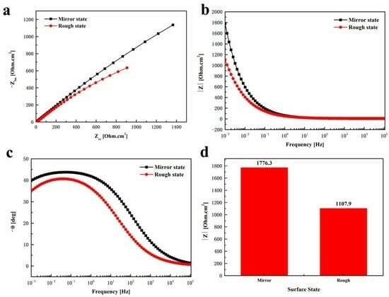
Figure 11.
The EIS curve of WBS composite with mirror and rough surface states, (a) Nyquist curves; (b,c) Bode curves; (d) total impedance |Z|.
As shown in Figure 12, the elements in the corrosion products are mainly W, O, B, N, and C. It is clear that cBN particles can be kept stable. The main corrosion product of WBS composite in NaCl solution is the oxide of W. To further determine the composition of corrosion products, the XPS patterns are shown in Figure 13. As shown in Figure 13b, the W 4f peak exhibited two components, which were attributed to the existence of WO3 4f 5/2 and WO3 4f 7/2 in the corroded surface [39]. WO3 is a common corrosion product of WC-based cemented carbide. Zhang et al. also found WO3 corrosion products in WC-Co cemented carbide [40]. Meanwhile, as shown in Figure 13c, SiO2 is also found in corrosion products, which can be attributed to oxidation of SiC whisker [41]. The Si element is not found in mapping EDS analysis because of its small content. As shown in Figure 13d, the cBN remains stable, which is consistent with the EDS result. Hence, it can be concluded that the corrosion products of WBS composite in NaCl solution are WO3 and a small amount of SiO2.
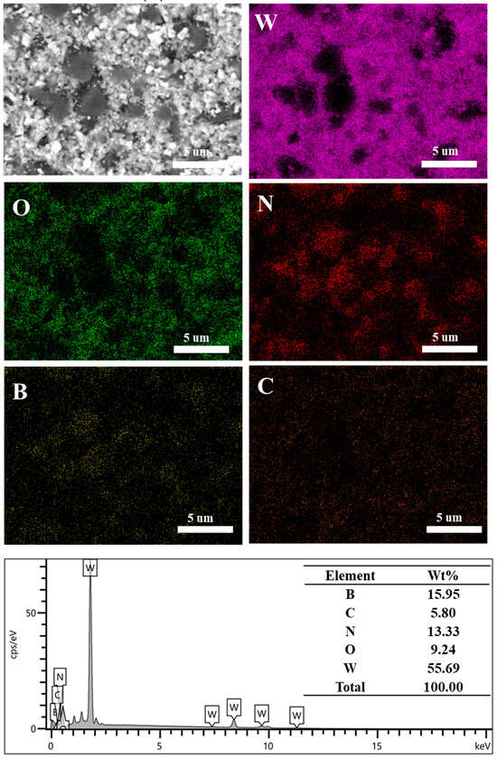
Figure 12.
SEM image and EDS analysis of corroded WBS composite.
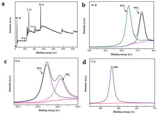
Figure 13.
XPS patterns of corrosion products of WBS composite in NaCl solution, (a) XPS survey; (b) W 4f scan curves; (c) O 1s scan curves; (d) N 1s scan curves.
According to the EDS and XPS results, cBN particles can be kept stable in NaCl solution. The main corrosion process is electrochemical corrosion of the WC phase. The cathode reaction and anode reaction are as follows:
Cathodic reduction:
Anodic oxidation:
The WO3 corrosion product on the surface of WBS composite accumulates continuously. However, the cathodic process is oxygen absorption corrosion in NaCl solution. The cathodic reduction will lead to an increase in PH value of the local solution. In local high OH− concentration solution, the WC phase will be continuously dissolved, as shown in Equation (5).
In summary, the surface damage induced by friction can indeed accelerate the corrosion rate of WBS composites in NaCl solution. However, as evidenced by the Icorr and Impedance, the corrosion resistance of WBS composites exhibits low sensitivity to surface damage. Meanwhile, surface damage does not alter the corrosion mechanism of WBS composites in NaCl solutions. The primary corrosion mechanism involves the oxidation and localized dissolution of WC, while the cBN phase remains stable.
4. Conclusions
In this study, the influence of applied load on the tribological behavior of a novel WC-cBN-SiCw composite was studied. The impact of corrosion resistance on surface damage induced by friction was also clarified. As the applied load increased from 20 N to 60 N, the frictional transition was found for WC-cBN-SiCw composite. The threshold of wear mechanism transformation is 40 N. As applied load exceed 40 N, the wear mechanisms transferred from abrasive wear to fatigue wear, which promotes the occurred of frictional transition. Higher loads promote the initiation of fatigue sources, which induces surface cracks. This is the main reason for the sudden change of friction coefficient, which corresponds to the frictional transition.
The surface damage induced by friction increases the corrosion rate of WC-cBN-SiCw composite in NaCl solution. However, the corrosion resistance of WC-cBN-SiCw composites exhibits low sensitivity to surface damage. Due to the stability of the reinforcing phase in NaCl solution, the surface damage did not affect the corrosion mechanism of the WC-cBN-SiCw composite. The corrosion mechanism can be described as the oxidation and localized dissolution of the WC phase, while the cBN phase remains stable. Because of its excellent wear and corrosion resistance, WC-cBN-SiCw composite is expected to be applied in special sealing parts of petrochemical equipment or high-pressure medium nozzles.
Author Contributions
The following contributions were made by each co-author. Conceptualization, B.F.; methodology, T.Q.; resources, J.Y. and Y.Z.; data curation, B.F. and J.W.; writing—original draft preparation, B.F.; writing—review and editing, B.F., C.C., J.S. and H.J. All authors have read and agreed to the published version of the manuscript.
Funding
This study was funded by The Natural Science Foundation of the Jiangsu Higher Education Institutions of China (No. 23KJB430037), Scientific Research Project of Wuxi Institute of Technology (No. BT2023-03).
Data Availability Statement
The data, supporting results, and reported results in general can be provided by the author upon request.
Acknowledgments
We greatly appreciate the grants and funds provided to carry out this study.
Conflicts of Interest
The authors declare no conflicts of interest.
Glossary
| Term | Definition |
| Multilayer Graphene (MLG) | A carbon-based nanomaterial composed of two to ten stacked graphene layers bound by weak van der Waals forces. |
| β-Si3N4 whisker (β-Si3N4w) | A single-crystalline fibrous microstructure of beta-phase silicon nitride (β-Si3N4), characterized by high aspect ratio, exceptional mechanical strength, thermal stability, and oxidation resistance. |
| Carbon Nanotubes (CNT) | Cylindrical nanostructures composed of rolled graphene sheets, classified as single-walled (SWCNT) or multi-walled (MWCNT) based on layer count. |
| SiC Whisker (SiCw) | A single-crystalline, high-aspect-ratio fibrous form of silicon carbide (SiC), typically exhibiting exceptional mechanical strength, thermal stability, and chemical inertness. |
| High Entropy Ceramics (HEC) | A class of ceramics comprising four or more principal metal cations in near-equimolar ratios, forming single-phase crystalline solid solutions stabilized by high configurational entropy. |
| WC-cBN-SiCw (WBS) | A kind of novel binderless hard material containing WC, cBN and SiC whisker. |
| Saturated Calomel Electrode (SCE) | A reference electrode composed of mercury (Hg), mercurous chloride (Hg2Cl2), and a saturated potassium chloride (KCl) solution. |
| Open Circuit Potential (OCP) | The equilibrium electrode potential of a material in an electrolyte when no external current flows, reflecting the balance between oxidation and reduction reactions at the material’s surface. |
| Electrochemical Impedance Spectroscopy (EIS) | A non-destructive analytical technique that measures the impedance of an electrochemical system across a range of frequencies by applying a sinusoidal AC voltage or current perturbation. |
| Polarization Curve (Tafel curve) | A plot of electrode potential versus current density (typically on a logarithmic scale) that characterizes the electrochemical kinetics of a system. |
| Friction Coefficient | A dimensionless scalar quantity representing the ratio of frictional force between two surfaces to the normal force pressing them together. |
| Wear Volume (V) | The total material volume removed from a surface due to mechanical wear processes (e.g., abrasion, adhesion), typically quantified via 3D profilometry. |
| Wear Rate (Kv) | The volumetric material loss per unit applied load and sliding distance. It quantifies material degradation under mechanical stress, serving as a key parameter for comparing wear resistance and predicting component durability in tribological systems. |
| Self-corrosion Potential (Ecorr) | The equilibrium electrode potential of a material in a corrosive electrolyte under open-circuit conditions, reflecting the thermodynamic tendency for spontaneous redox reactions (e.g., metal oxidation and cathodic reduction) to occur. |
| Self-corrosion Current Density (Icorr) | The current density corresponding to the equilibrium rate of spontaneous corrosion reactions (oxidation and reduction) on a material’s surface in a corrosive medium under open-circuit conditions. |
References
- Yang, L.; Liao, C.; Cao, C.; Zhang, H.; Gong, D.; Wan, L.; Wang, R. Preparation of extra coarse-grained WC-Co cemented carbides by doping sodium in the ammonium tungstate solution during evaporation crystallization process. Ceram. Int. 2024, 50, 12203–12211. [Google Scholar] [CrossRef]
- Agode, K.; Wolff, C.; Guven, M.; Nouari, M. Modelling of the damage initiation at WC/WC and WC/Co boundaries in WC-Co tool material at the microstructure scale: Application to the tool/chip contact. Int. J. Refract. Met. Hard Mater. 2024, 119, 106508. [Google Scholar] [CrossRef]
- Li, H.; Zhang, H.; Chen, D.; Zhu, Y.; Jiang, Z. Analysis of interface microstructure and element diffusion of WC-Co-Ni-Fe powder and M2 high-speed steel composite. Mater. Chem. Phys. 2024, 315, 128976. [Google Scholar] [CrossRef]
- Wang, X.; Guo, J.; Hwang, K.S.; Fang, Z.Z. Review and recent progress on developments of functionally graded WC-Co via a carburizing process: Principles, insights, and industrial implications. Int. J. Refract. Met. Hard Mater. 2024, 118, 106443. [Google Scholar] [CrossRef]
- Sun, J.; Zhao, J.; Gong, F.; Ni, X.; Li, Z. Development and Application of WC-Based Alloys Bonded with Alternative Binder Phase. Crit. Rev. Solid State Mater. Sci. 2019, 44, 211–238. [Google Scholar] [CrossRef]
- Yang, J.; Chen, W. Unravelling the landscape of global cobalt trade: Patterns, robustness, and supply chain security. Resour. Policy 2023, 86, 104277. [Google Scholar] [CrossRef]
- Bastian, S.; Busch, W.; Kühnel, D.; Springer, A.; Meißner, T.; Holke, R.; Scholz, S.; Iwe, M.; Pompe, W.; Gelinsky, M.; et al. Toxicity of Tungsten Carbide and Cobalt-Doped Tungsten Carbide Nanoparticles in Mammalian Cells in Vitro. Environ. Health Perspect. 2009, 117, 530–536. [Google Scholar] [CrossRef] [PubMed]
- Qin, J.; Hui, J.; Zhou, Y.; Dong, W.; Luo, Y.; Zhu, S. Processing of ZrO2 strengthened and toughened WC matrix composites based on ML. J. Eur. Ceram. Soc. 2024, 44, 5528–5540. [Google Scholar] [CrossRef]
- Vázquez-Pelayo, A.; Becerril-Juarez, I.; Mireles, L.; Flores-Zúñiga, H.; Avalos-Borja, M. TaC-WC synthesis by a new approach of mechanical milling and low-temperature spark plasma sintering. Mater. Today Commun. 2024, 38, 108433. [Google Scholar] [CrossRef]
- Silva, M.C.; Leite, M.M.; Raimundo, R.A.; Henriques, G.F.; Valcacer, S.M.; Mashhadikarimi, M.; Morales, M.A.; Gomes, U.U. Consolidation and mechanical properties of WC-Al2O3 composite prepared via high energy ball milling and spark plasma sintering. Ceram. Int. 2022, 48, 19026–19035. [Google Scholar] [CrossRef]
- Radajewski, M.; Schimpf, C.; Krüger, L. Study of processing routes for WC-MgO composites with varying MgO contents consolidated by FAST/SPS. J. Eur. Ceram. Soc. 2017, 37, 2031–2037. [Google Scholar] [CrossRef]
- Sun, J.; Zhao, J.; Huang, Z.; Yan, K.; Shen, X.; Xing, J.; Gao, Y.; Jian, Y.; Yang, H.; Li, B. A Review on Binderless Tungsten Carbide: Development and Application. Nano-Micro Lett. 2019, 12, 13. [Google Scholar] [CrossRef] [PubMed]
- Wang, Z.; Liu, Y.; Zou, B.; Huang, C.; Xue, K.; Shi, Z. Mechanical properties and microstructure of Al2O3-SiCw ceramic tool material toughened by Si3N4 particles. Ceram. Int. 2020, 46, 8845–8852. [Google Scholar] [CrossRef]
- Cheng, Y.; Zhu, T.; Sun, N.; Li, Y.; Xie, Z.; Liao, N.; Sang, S.; Liang, X.; Dai, J. Synergistic strengthening and toughening of oscillatory pressure sintered WC-ZrO2-Al2O3 ceramics. J. Alloys Compd. 2022, 922, 166133. [Google Scholar] [CrossRef]
- Sun, J.; Zhao, J.; Chen, Y.; Wang, L.; Yun, X.; Huang, Z. Macro-micro-nano multistage toughening in nano-laminated graphene ceramic composites. Mater. Today Phys. 2022, 22, 100595. [Google Scholar] [CrossRef]
- Cai, H.; Jing, W.; Guo, S.; Liu, L.; Ye, Y.; Wen, Y.; Wu, Y.; Wang, S.; Huang, X.; Zhang, J. Effects of micro/nano CeO2 on the microstructure and properties of WC-10Co cemented carbides. Int. J. Refract. Met. Hard Mater. 2021, 95, 105432. [Google Scholar] [CrossRef]
- Chen, F.; Yan, K.; Zhou, J.; Zhu, Y.; Hong, J. High toughness Si3N4 ceramic composites synergistically toughened by multilayer graphene/β-Si3N4 whisker: Preparation and toughening mechanism investigation. J. Alloys Compd. 2022, 921, 166183. [Google Scholar] [CrossRef]
- Sun, J.; Zhao, J.; Chen, Y.; Wang, L.; Yun, X.; Huang, Z. Toughening in low-dimensional nanomaterials high-entropy ceramic nanocomposite. Compos. Part B Eng. 2022, 231, 109586. [Google Scholar] [CrossRef]
- Mao, C.; Zhou, F.; Hu, Y.; Cai, P.; Jiang, Y.; Bi, Z.; Peng, G. Tribological behavior of cBN-WC-10Co composites for dry reciprocating sliding wear. Ceram. Int. 2019, 45, 6447–6458. [Google Scholar] [CrossRef]
- Mao, C.; Zhang, Y.; Peng, X.; Zhang, B.; Hu, Y.; Bi, Z. Wear mechanism of single cBN-WC-10Co fiber cutter in machining of Ti-6Al-4V alloy. J. Mater. Process. Technol. 2018, 259, 45–57. [Google Scholar] [CrossRef]
- Mao, C.; Ren, Y.; Gan, H.; Zhang, M.; Zhang, J.; Tang, K. Microstructure and mechanical properties of cBN-WC-Co composites used for cutting tools. Int. J. Adv. Manuf. Technol. 2015, 76, 2043–2049. [Google Scholar] [CrossRef]
- Wu, J.; Zhang, Z.; Wang, H.; Wang, C.; Hou, Z.; Wu, D.; Ouyang, X. High-pressure synthesis of tungsten carbide–cubic boron nitride (WC–cBN) composites: Effect of cBN particle size and volume fraction on their microstructure and properties. Int. J. Refract. Met. Hard Mater. 2023, 110, 106037. [Google Scholar] [CrossRef]
- Wu, J.; Wang, H.; Wang, C.; Tang, Y.; Hou, Z.; Wan, S.; Liu, B.; Wu, D.; Chen, B.; Tan, Z.; et al. High pressure synthesis of tungsten carbide–cubic boron nitride (WC-cBN) composites: Effect of thermodynamic condition and cBN volume fraction on their microstructure and properties. J. Eur. Ceram. Soc. 2022, 42, 4503–4512. [Google Scholar] [CrossRef]
- Wang, B.; Matsumaru, K.; Yang, J.; Fu, Z.; Ishizaki, K. The Effect of cBN Additions on Densification, Microstructure and Properties of WC-Co Composites by Pulse Electric Current Sintering. J. Am. Ceram. Soc. 2012, 95, 2499–2503. [Google Scholar] [CrossRef]
- Wang, Z.; Liu, Y.; Liu, K.; Wang, B. Mechanical properties and microstructure of spark plasma sintered WC-8 wt.%Co-VC-cBN ultrafine grained cemented carbide. Ceram. Int. 2019, 45, 23658–23665. [Google Scholar] [CrossRef]
- Sun, J.; Chen, Y.; Zhai, P.; Zhou, Y.; Zhao, J.; Huang, Z. Tribological performance of binderless tungsten carbide reinforced by multilayer graphene and SiC whisker. J. Eur. Ceram. Soc. 2022, 42, 4817–4824. [Google Scholar] [CrossRef]
- Sun, J.; Zhao, L.; Li, X.; Du, Q.; Zhao, J.; Zhou, Y.; Zhang, L.; Li, A. Effect of graphene and SiC whisker on the mechanical properties of WC-TiC-TiN-Al2O3 nanocomposites. J. Alloys Compd. 2023, 938, 168612. [Google Scholar] [CrossRef]
- Fan, B.; Zhang, Y.; Wang, J.; Qin, T.; Song, J.; Yu, Z.; Zhang, X. Effect of sintering temperature on mechanical properties of WC-cBN-SiCw composites with multi-scale and multi-morphology toughening strategy. Mater. Lett. 2024, 374, 137183. [Google Scholar] [CrossRef]
- Chen, Z.; Ji, L.; Guo, N.; Xu, C.; Zhang, S. Crack healing and strength recovery of Al2O3/TiC/TiB2 ceramic tool materials. Int. J. Refract. Met. Hard Mater. 2020, 87, 105167. [Google Scholar] [CrossRef]
- He, R.; Hu, P.; Zhang, X.; Han, W.; Wei, C.; Hou, Y. Preparation of high solid loading, low viscosity ZrB2-SiC aqueous suspensions using PEI as dispersant. Ceram. Int. 2013, 39, 2267–2274. [Google Scholar] [CrossRef]
- Zhang, X.; Zhang, L.; Yang, Z.; Zhu, X.-C.; He, Y.; Kang, X. Tracing the evolution of contact area during the running-in process of AgCu-MoS2 composite. Tribol. Int. 2022, 174, 107739. [Google Scholar] [CrossRef]
- Tan, Z.; Zhang, M.; Zhao, S.; Huang, Y.; Huang, Z. Microstructure, mechanical and friction-wear properties of SiC-WC composite with Al and C as sintering aids. J. Eur. Ceram. Soc. 2024, 44, 3557–3568. [Google Scholar] [CrossRef]
- Wang, Z.; Wang, G.; Song, Z.; Liu, S.; Zhou, Y.; Qiu, X.; Wu, C.; Wang, X.; Chen, Z.; Meng, C. Microstructure evolution, wear and corrosion behavior of WC reinforced CoCrFeNiMn high-entropy alloy composite coatings by induction cladding. Surf. Coat. Technol. 2024, 486, 130938. [Google Scholar] [CrossRef]
- Zhang, B.; Ma, X.; Liu, L.; Wang, Y.; Yu, H.; Morina, A.; Lu, X. Reciprocating sliding friction behavior and wear state transition mechanism of cylinder liner and piston ring. Wear 2024, 546–547, 205293. [Google Scholar] [CrossRef]
- Ghosh, G.; Sidpara, A.; Bandyopadhyay, P. Understanding the role of surface roughness on the tribological performance and corrosion resistance of WC-Co coating. Surf. Coat. Technol. 2019, 378, 125080. [Google Scholar] [CrossRef]
- Wang, Z.; Feng, Z.; Fan, X.-H.; Zhang, L. Pseudo-passivation mechanism of CoCrFeNiMo0.01 high-entropy alloy in H2S-containing acid solutions. Corros. Sci. 2021, 179, 109146. [Google Scholar] [CrossRef]
- Konadu, D.; van der Merwe, J.; Potgieter, J.; Potgieter-Vermaak, S.; Machio, C. The corrosion behaviour of WC-VC-Co hardmetals in acidic media. Corros. Sci. 2010, 52, 3118–3125. [Google Scholar] [CrossRef]
- Wang, Z.B.; Hu, H.X.; Liu, C.B.; Zheng, Y.G. The effect of fluoride ions on the corrosion behavior of pure titanium in 0.05M sulfuric acid. Electrochim. Acta 2014, 135, 526–535. [Google Scholar] [CrossRef]
- Han, B.; Zhu, S.; Dong, W.; Bai, Y.; Ding, H.; Luo, Y.; Di, P. Improved mechanical performance and electrochemical corrosion of WC-Al2O3 composite in NaCl solution by adding the TiC additives. Int. J. Refract. Met. Hard Mater. 2021, 99, 105566. [Google Scholar] [CrossRef]
- Zhang, L.; Chen, Y.; Wan, Q.L.; Liu, T.; Zhu, J.F.; Tian, W. Electrochemical corrosion behaviors of straight WC-Co alloys: Exclusive variation in grain sizes and aggressive media. Int. J. Refract. Met. Hard Mater. 2016, 57, 70–77. [Google Scholar] [CrossRef]
- Esfandiari, N.; Kashefi, M.; Mirjalili, M.; Afsharnezhad, S. Role of silica mid-layer in thermal and chemical stability of hierarchical Fe3O4-SiO2-TiO2 nanoparticles for improvement of lead adsorption: Kinetics, thermodynamic and deep XPS investigation. Mater. Sci. Eng. B 2020, 262, 114690. [Google Scholar] [CrossRef]
Disclaimer/Publisher’s Note: The statements, opinions and data contained in all publications are solely those of the individual author(s) and contributor(s) and not of MDPI and/or the editor(s). MDPI and/or the editor(s) disclaim responsibility for any injury to people or property resulting from any ideas, methods, instructions or products referred to in the content. |
© 2025 by the authors. Licensee MDPI, Basel, Switzerland. This article is an open access article distributed under the terms and conditions of the Creative Commons Attribution (CC BY) license (https://creativecommons.org/licenses/by/4.0/).