Abstract
Achieving keyhole-free joints is critical in Friction Stir Spot Welding (FSSW). This study presents a new approach to eliminate this volumetric defect in AA6082-T6 FSSW sheet joints using a continuous multi-layer Friction Stir Deposition (CMFSD) technique, employing a newly designed AA6082-T6 consumable tool. FSSW was performed at various rotational speeds (350, 550, 750 and 950 rpm) with a 5 s dwell time. Comprehensive macro- and micro-scale evaluations, along with mechanical properties (hardness and tensile-shear load) of the produced joints, were conducted. Additionally, microstructures were examined using Optical Microscopy (OM), while fracture surfaces were analyzed via Scanning Electron Microscopy (SEM). Optimal FSSW conditions were identified at 550 rpm, yielding a stir zone (SZ) hardness of 94.6 ± 1.4 HV and a maximum tensile-shear load of 4.73 ± 0.27 kN. The keyhole was successfully refilled using AA6082-T6 rod material via CMFSD, resulting in a defect-free joint of the same base alloy. Electron Backscattered Diffraction (EBSD) technique was also used to examine the microstructural features. A comparative analysis revealed significant enhancements: the refilled FSSW joints exhibited a 46.5% increase in maximum tensile-shear load and a 66.66% improvement in elongation to failure compared to the highest-FSSW joint performance with the keyhole defect.
1. Introduction
Recently, with the requirement for carbon dioxide emission reduction and energy saving, high strength aluminum alloys (6xxx-series) have been widely employed in the automotive, shipbuilding and aerospace industries because of their remarkable specific strength, excellent damping capacity and low density [1,2,3,4]. Consequently, effective joining techniques for these aluminum alloys have attracted growing global interest. When traditional fusion welding is used, the joints often develop numerous defects like lack of fusion, porosity and solidification cracks [5,6,7,8]. Furthermore, weld joint distortion when welding thin aluminum sheet thicknesses can significantly deteriorate the welding joint’s mechanical properties [9].
As a solid-state welding process, friction stir spot welding (FSSW) has several benefits over fusion spot welding, including high joint performance, minimal joint distortion, absence of cracks, low power consumption, and no emissions [10,11]. As a result, FSSW is widely used in the transportation and electronics industries. Therefore, many efforts have been made to optimize its process parameters for welding different metals and alloys in similar or dissimilar lap joints, such as tool design [12,13,14], rotational speed [15,16,17], dwell time [5], plunge depth [18], plunge speed [19] and downward force [20]. The flow of materials at the FSSW joint interface is determined by the tool design, plunging rate, dwell time, and downward force; however, the generation of frictional heat is mostly dependent on the tool’s rotational speed [20,21,22]. However, despite its many advantages, FSSW is susceptible to several common weld imperfections that can compromise joint integrity and performance. These include hooking, which characterized by the upward bending and thinning of the upper sheet due to excessive tool penetration. This directly reduces the bonded ligament length and joint strength [2,3,4]. Additionally, flash formation, which resulting from material expulsion during tool plunge, can lead to material loss and negatively affect the joint’s aesthetic quality [5,15,17]. Foremost among these, and a critical focus of current research, is the keyhole defect, which is a result of the tool being removed from the workpiece at the final stage of the welding process [23,24]. This defect is a cylindrical cavity that remains at the core of the spot lap welds [25]. It presents a number of difficulties, especially in applications where corrosion resistance, surface quality, aesthetics, and fatigue resistance are crucial. This is a critical concern in the automotive and aerospace industries, where joint performance is vital. Therefore, techniques for refilling or eliminating the keyhole defect have become a research hotspot [26,27,28,29]. To address this, various techniques have been developed and explored in the literature, each with distinct advantages and inherent limitations [25,30,31,32]. Among these, pinless FSSW can provide a smoother surface finish compared to traditional FSSW with a pin, as there is no exit hole that requires post-processing [32]. In contrast, it has limitations regarding the joint strength, thickness, and complex configurations, making it only suited for simple, thin-sheet welding applications [25]. As a result, this technique is not well-suited for spot joining high-strength aluminum alloys used in structural applications.
Lunetto et al. [29] examined two techniques: Active Filling Friction Stir Repair (AF-FSR) and Passive Filling Friction Stir Repair (PF-FSR) for repairing pre-drilled holes in AISI 304 stainless steel. This work highlights the challenges of repairing high-melting-point metals and evaluates the impact of process parameters and filler materials on repair quality. The authors demonstrated that PF-FSR offers superior mechanical strength and defect-filling capabilities. Ji et al. [23] succeeded in filling the keyhole defect of AZ31-B magnesium friction stir welds through a complex mechanical technique named active-passive filling friction stir repairing. In this technique, three non-consumable pinless tools having the same shoulder features (a six-spiral-flute shoulder) and different diameters (6, 10, and 14 mm) were used to refill the keyhole defect in the presence of an extra filler material. The refilling process was achieved at a constant tool rotational speed of 1300 rpm, a holding time of 5 s and various plunge speeds (1, 2, 4 and 6 mm/min). According to their results, a plunge speed of 1 mm/min and a rotational speed of 1300 rpm produced a defect-free joint. In contrast, Silva et al. [33] were unable to produce defect-free refilled FSSW joints in 2 mm thick AA6082-T6 alloy using the refilling FSSW technique (RFSSW), which utilizes a multi-part tool system (pin, sleeve, and clamping ring). Their experiments, using the suggested parameters, resulted in three different hook defect configurations in the AA6082-T6 lap joints. They concluded that these hook defects were related to the direction and position of the material flow around the sleeve, as well as the development of the drop zone during the plunging and retracting stages. Tier et al. [34] also concluded the formation of volumetric defects using the same technique, RFSSW prototype machine: Sleeve plunge variant, during the RFSSW of 1.5 mm thick AA5052-O aluminum alloy to produce lap joints. In contrast, Reimann et al. [3] based on the concept of utilizing a probe, sleeve and clamping ring tool setup system, succeeded to refill a keyhole of 7.5 mm in diameter of the FSSW AA6061-T6 aluminum sheet using a cylindrical plug of the same alloy material. The plug was joined to the surrounding keyhole cavity through a friction spot welding process, which created a sealed keyhole. The results showed that they achieved flawless welds without any reduction in strength compared to the spot joints in the bead-on-plate specimens. In fact, this technique is time-consuming, complex, and involves several procedures. Furthermore, it is crucial to optimize the process parameter. Zhao et al. [18] also attempted to FSSW a 7B04-T74 aluminum alloy (1.9 mm thick) sheets in lap-joints with avoiding the formation of a keyhole defect via a refilling method employing a movable tool assembly. Their results demonstrated that the optimal joint strength was achieved at a 3 mm tool plunge depth. However, this approach required additional post-weld treatment to eliminate groove defects. While these aforementioned techniques aim to address the keyhole defect, they often present significant collective limitations. These include the necessity for specialized tools or complex equipment, leading to increased process complexity, prolonged cycle times, and higher overall costs. Furthermore, some methods may not fully eliminate defects or are unsuitable for high-strength structural alloys.
Therefore, this work addresses the need for simpler and less time-consuming FSSW procedures for high-strength Al alloys, where most prior research employs high tool rotational speeds (>1000 rpm) [35,36,37]. This study investigates the feasibility of FSSW of 1 mm to 2 mm thick AA6082-T6 Al alloy sheets at low rotational speeds, aiming to optimize weld quality through a focused investigation into the isolated effects of rotational speed. This work additionally aims to refill the keyhole in the produced high-performance spot-joint. The refilling process of this volume defect was achieved using a newly designed AA6082-T6 consumable rod of the same base alloy. This process employs an additive manufacturing technology called continuous multi-layer friction stir deposition (CMFSD). Unlike the aforementioned refilling approaches by Reimann et al. [3], Zhao et al. [18], Ji et al. [23], Ikumapayi et al. [25], Lunetto et al. [29], Muhayat et al. [32], Silva et al. [33], and Tier et al. [34], our proposed CMFSD represents an advanced solid-state additive manufacturing (AM) technique for keyhole refilling. Unlike fusion-based AM methods, CMFSD builds material layer-by-layer without melting, using a combination of frictional heat and severe plastic deformation to consolidate metallic feedstock into fully dense structures [38,39]. The process involves a rotating consumable tool that plunges into the substrate or previous layer, generating heat through interfacial friction and mechanically stirring the material to form strong metallurgical bonds [40]. In this study, we modified our existing FSSW machine to perform the CMFSD process, employing optimized parameters with an AA6082-T6 consumable rod to directly refill the keyhole defects in the AA6082-T6 FSSW joints. This solid-state refilling process with similar materials inherently simplifies material management and ensures metallurgical compatibility. While the current laboratory setup involves distinct steps, this approach holds significant potential for integration into automated multi-tool FSW systems, which would streamline the process, reduce overall cycle time, and potentially lower costs compared to methods requiring complex tool changes, dissimilar fillers, or extensive post-treatments. Finally, a thorough evaluation was conducted on both the conventional AA6082 FSSW and the subsequent refilled lap joints. This assessment covered joint appearance, macroscopic and microscopic structural features, hardness measurements, tensile-shear strength values, and fracture behaviors. Electron backscattered diffraction (EBSD) was also utilized to study the grain structure features.
2. Materials and Methods
2.1. Initial Materials
Similar FSSW lap joint configurations were accomplished on AA 6082-T6 aluminum alloy using different sheet thicknesses of 1 mm for the upper sheet and 2 mm for the lower sheet, as designed for all the spot-welded joints. The width and length of both aluminum sheets were 40 mm × 130 mm, respectively. The two alloy sheets were overlapped by 40 mm and the FSSW was achieved at the center of the lapped areas. The keyhole filling process was carried out using AA 6082-T6 consumable aluminum rods, with a length of 150 mm and a 25 mm diameter. The 6082 alloy materials were provided by Future Fond Company, Milan, Italy. Their elemental compositions were verified by Foundry-Master Pro (Oxford Instruments, Abingdon, UK), as detailed in Table 1. In addition, the measured mechanical properties in terms of Yield strength, ultimate tensile strength, elongation at break (%) and hardness (HV0.3) were also measured and are presented in Table 2.

Table 1.
Lists the chemical composition (in wt.%) of the AA6082 alloy base materials.

Table 2.
Lists the mechanical properties of the three AA6082-T6 alloy base materials.
2.2. Friction Stir Spot Welding and Keyhole Refilling
A fully automatic FSW machine (EG-FSW-M1) [41] was used to achieve both the FSSW and keyhole refilling processes. The specific range of low rotational speeds was chosen to investigate their effect on joint quality, a less-explored area for this alloy, supported by insights from existing literature [42,43].
Based on this approach, the two AA6082-T6 sheet specimens were friction stir welded in lap joints at four different tool rotational speeds of 350, 550, 750 and 950 rpm while maintaining a constant 5 s dwell period. This 5 s welding time was selected based on preliminary trials, which confirmed its adequacy for achieving defect-free joints in the specified thickness range. This fixed parameter enabled a focused investigation into the isolated effects of rotational speed on weld quality, a crucial step for optimizing industrial processes that prioritize shorter cycle times in automotive and aerospace applications. The remaining FSSW parameters, specifically the plunge rate, tilt angle and plunge depth were held fixed at 0.1 mm/s, 0°, and 2.5 mm, respectively. For the joining process, an AISI H13 steel tool was utilized. The FSSW tool is a tapered cylindrical pin tool with an 11.3° tapered angle. Its dimensions are: a 20 mm shoulder diameter, a 6 mm pin diameter at the shoulder, a 5 mm pin diameter at the tip, and a 2.5 mm pin length. Figure 1 represents the tool shape and dimensions. The specific dimensions and the selection of AISI H13 as the tool material were guided by established research [44,45,46].
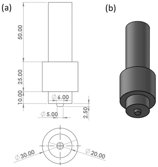
Figure 1.
Shows the FSSW welding tool, (a) a schematic drawing and (b) an isometric view of the FSSW tool, with all dimensions specified in mm.
The FSSW process involved four stages, which are depicted in Figure 2. During the first stage, the loose AA6082 lap sheets were fixed on the FSSW machine table to achieve the lap-joint and the designed FSSW tool was also well fixed in the machine shank (Figure 2a). The second step represents the adjusting of FSSW parameters and the beginning of ploughing and stirring (Figure 2b). Achieving the desired welding duration while maintaining a constant tool rotational speed and pin insertion constitutes the third stage (Figure 2c). The welding joint is typically completed at this step. The fourth stage (Figure 2d) represents the exit of tool from the FSSW joint, which is characterized by the appearance of the keyhole and the shoulder projection. Both the keyhole formation and the shoulder projection are considered the main FSSW disadvantages [23,47].
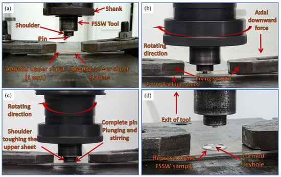
Figure 2.
Outlines the FSSW stages to produce AA6082-T6 lap joints: (a) clamping and tool setup, (b) plunging and initial stirring, (c) dwelling and welding, and (d) tool retraction and keyhole formation.
The temperature near the stir zone (SZ) for the FSSW joints was recorded using a type-K thermocouple connected to an advanced digital multimeter (UT61B, Hangzhou, Zhejiang, China). The thermocouple tip was positioned between the overlapping sheets within the 40 mm × 40 mm overlap region, specifically at a location 10 mm from the keyhole centerline. This placement was chosen to facilitate the thermocouple’s extraction after welding while preventing it from being damaged by the tool’s stirring action. This strategic placement minimized potential heat loss from convection and conduction, providing a reliable record of the thermal cycle. Given the high thermal conductivity of AA6082-T6 (170 W/m·K) and the consistent measurement method, the measured values are representative of the temperature within the process zone. Temperature data were recorded continuously throughout the welding process. After welding, the joint was cooled to room temperature before fixture removal. The thermal history of the process was analyzed by plotting the recorded temperatures against time.
Recently, friction stir deposition has been employed to build continuous multi layers on various substrates with excellent bonding capabilities [48,49,50]. In the current study, an AA6082-T6 rod was used as a keyhole filling material (consumable tool).
It was machined to match dimensions of the FSSW tool, including the shoulder diameter and the pin’s shape and size. Figure 3 represents the refilling steps of the AA6082 FSSW joints, which involve: First, the suggested AA6082-T6 consumable rod is secured within the FSW machine’s spindle shank (Figure 3a). During this setup, the consumable pin’s axis is precisely aligned with the keyhole’s axis in the FSSW joint. Second, the consumable tool is rotated at a constant rotating speed of 450 rpm and a constant descending speed of 1 mm/min towards the keyhole of the FSSW AA6082-T6 joint (Figure 3b). The descending of the consumable tool continues until its shoulder touches the FSSW joint’s upper surface (the FSSW tool projection) and the pin touches the bottom of the FSSW keyhole. This leads to the beginning of building process from the bottom up via depositing continuous layers arising from the heat generated between the consumable rod material and the keyhole cavity. This high frictional heat causes the consumable rod (AA6082-T6 aluminum alloy) to plastically deform under the applied feeding rate of 1 mm/min. Consequently, the softened material from the rod was thus transferred into the keyhole defect, accumulating upwards to achieve a refilled state, as depicted in Figure 3c. Examples of refilled FSSW joints are given in Figure 3d.
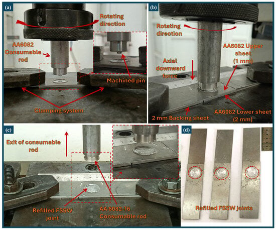
Figure 3.
Keyhole refilling stages via a friction stir deposition to produce defect-free AA6082-T6 FSSW lap joints: (a) setup and alignment of the consumable rod with the keyhole, (b) descending and rotation into the keyhole, (c) bottom-up deposition and filling process and (d) representative samples of the refilled joints.
2.3. Characterization of the Unrefilled-FSSW and Refilled Joints
Standard metallographic techniques, including grinding and polishing, were employed to prepare sections of both the AA6082-T6 friction stir spot-welded joints and the refilled specimens. This preparation facilitated subsequent macro- and microstructural examinations, as well as hardness testing. Prior to microstructure investigation, all polished specimens were treated with a solution—composed of 95 mL distilled water, 2.5 mL nitric acid, 1.5 mL hydrochloric acid, 1 mL hydrofluoric acid. Metallographic investigation was performed with an Olympus (Type-BX41M-LED, Olympus, Tokyo, Japan) optical microscope (OM). The same OM was also used to measure the grain size, based on the linear intercept method.
Hardness measurements were conducted utilizing a Vickers hardness tester (Type-HWDV-75, TTS Unlimited, Osaka, Japan). A consistent load of 300 g was applied, with an indentation dwell time of 15 s. Hardness was conducted on the cross-sections of both the FSSW and the keyhole-refilled joints by making two distinct horizontal lines (Figure 4). The first line was located in the middle of the upper AA6082-T6 sheet, precisely 0.5 mm from its top surface. The second measurement line was located in the middle of the lower AA6082-T6 sheet, corresponding to a distance of 1.5 mm from the first line. Readings were taken along these lines with leaving a distance of 0.7 mm between each two impressions. The collected values were plotted to represent the hardness profiles at different FSSW conditions. Additionally, the hardness measurements of the refilled joint were plotted in a map. A 30-ton (Type-WDW-300D, Jinan, China) universal tensile testing apparatus was utilized for the tensile-shear assessments, with a cross-head speed set at 0.1 mm/min. A gauge length of 12 cm was maintained for all samples. The elongation values were recorded as the cross-head displacement of the testing machine, which served as a consistent and reliable measure for comparative analysis across all specimens. To ensure proper axial load application, 1 mm and 2 mm thick AA6082-T6 aluminum backing sheets were used (Figure 5 and Figure 6). Subsequent to these tests, the fracture surfaces of the separated FSSW and refilled joint specimens were analyzed via a scanning electron microscope (SEM-Quanta FEG 250-FEI, Hillsboro, OR, USA). This instrument was equipped with advanced energy-dispersive spectroscopy (EDS) and EBSD systems. Specimens (FSSW and RFSSW joints) prepared for EBSD investigation were mechanically polished and further electropolished for 60 s in a solution of 30 vol.% of nitric acid, and 70 vol.% of methanol at a temperature of −15 °C and a voltage of 15 V. The OIM datasets were acquired with a 0.5 μm step, an accelerating voltage of 20 kV, and a 15 mm working distance. Post-acquisition, these datasets were analyzed using TSL OIM Analysis 7.2 software.

Figure 4.
Details the specific positions of the hardness profiling lines during testing for: (a) the FSSW AA6082-T6 and (b) the refilled FSSW joints.
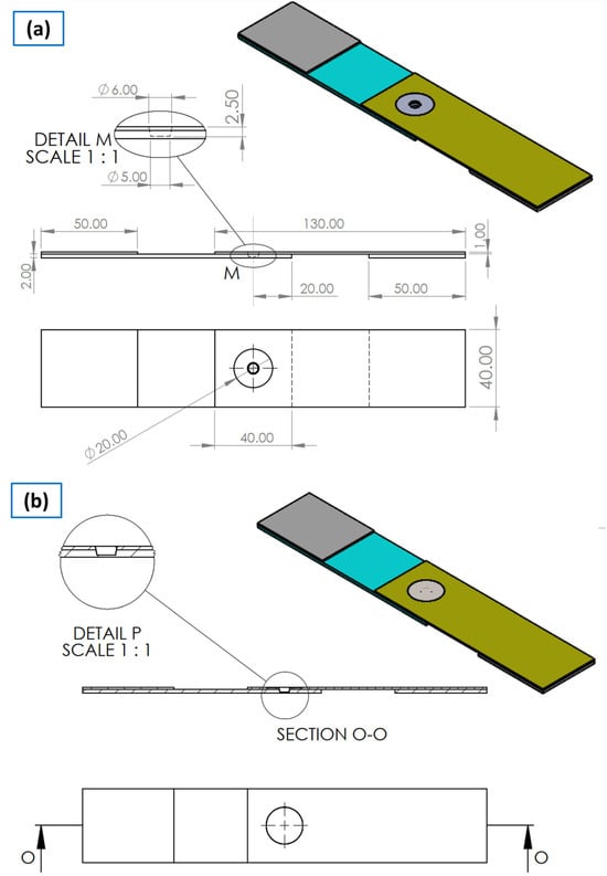
Figure 5.
Represents a schematic of (a) a tensile-shear test specimen of the FSSW AA6082-T6 joint and (b) the refilled FSSW joint. The colors denote different components of the joint and the backing sheets, which are used to ensure alignment during testing. All dimensions are specified in mm.
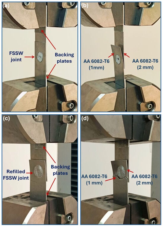
Figure 6.
Photo-images showing the FSSW and refilled FSSW of AA6082-T6 joints: (a,c) during testing and (b,d) after testing.
3. Results
3.1. Surface Appearance of Spot Welds
Figure 7 represents the top surface condition of the FSSW AA6082-T6 joints produced at various rotational speeds of 350, 550, 750, and 950 rpm with a fixed dwell time of 5 s. The results show that the carefully chosen FSSW factors in this work were successful in spot-joining the AA6082-T6 aluminum strips, which had different thicknesses of 1 mm (upper sheet) and 2 mm (lower sheet). The distinctive marks of the FSSW in terms of the shoulder projection (outer circle where the tool shoulder comes in contact with the upper AA6082-T6 sheet) and keyhole (inner circular area, which is the pin penetration area) appear clearly and completely round without distortion in the spot-welding joints. This indicates the efficiency of the fixation system and the good selection of the applied heat input despite the thin thickness of the spot-welded samples. It has been reported that an increase in tool rotational speed at a constant dwell time increases the heat input introduced to the FSSW joints, which increases the plasticity of the material beneath the tool shoulder and may cause a circular flash [5]. This phenomenon was observed in Figure 7c,d at the high rotational speeds of 750 and 950 rpm, respectively. The dimensions of the keyhole and the extent of this shoulder projection of the FSSW AA6082-T6 are directly influenced by thermal and mechanical energies during the friction stiring process. The shoulder volume for the joints processed at 350, 550, 750, and 950 rpm was 27.434 mm3, 94.234 mm3, 157.034 mm3, and 237.434 mm3, respectively. This data shows a clear trend of increasing shoulder volume with higher rotational speeds., In addition, the measured keyhole volumes increase nonlinearly with rotation speed: 80.5 mm3 at 350 rpm, 147.3 mm3 at 550 rpm, 210.1 mm3 at 750 rpm, and 290.5 mm3 at 950 rpm. The nonlinear growth pattern reflects the complex interplay between thermal softening and material flow dynamics. Insufficient heat input at lower rotational speeds (≤350 rpm) can result in incomplete material plasticization, potentially causing irregularly shaped keyholes due to inadequate material flow upon pin retraction. Conversely, high rotational speeds (≥750 rpm) can generate excessive heat, leading to uncontrolled material extrusion and increased burr formation. The value of 550 rpm provides a favorable balance between the welding conditions, resulting in effective material plasticization and controlled flow, thereby contributing to the formation of a high-quality joint.
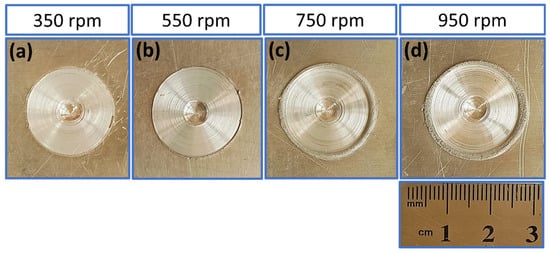
Figure 7.
Shows top appearance of surface morphology of the AA6082-T6 FSSW joints produced at various too rotational speeds: (a) 350 rpm, (b) 550 rpm, (c) 750 rpm and (d) 950 rpm, while maintaining a constant 5 s dwell time.
3.2. Temperature Profile During the FSSW Process
Temperature begins to generate when the pin is inserted into the upper sheet of the AA6082-T lap joint during the plunge stage. The tool shoulder then contacts the top surface, causing the temperature to rise rapidly. The tool shoulder causes frictional deformation and the pin causes plastic deformation. Finally, the tool is pulled from the FSSW joint, and it is cooled to room temperature. The thermal history profiles of the AA6082-T6 FSSW joints processed at different tool rotational speeds (350–950 rpm) and a constant dwell time of 5 s are given in Figure 8. The measuring temperatures were plotted against time. It is evident from Figure 8 that while the peak temperatures at each tool rotational speed vary, the thermal cycle profile for all produced spot-welds shows the same trend. The thermal cycle of the FSSW shows three stages. (1) Heating stage: As the tool rotates and penetrates the aluminum sheets, friction between the tool and material generates heat. Higher rotational speeds (750 and 950 rpm) produce more heat due to increased frictional energy, causing faster heating and higher peak temperatures. Lower rotational speeds (350 and 550 rpm) result in slower heating and lower peak temperatures. It can be concluded that higher rotational speeds led to higher peak temperatures, driven by the increased frictional heat generated throughout the stirring operation. It attains the value of 238, 269, 301, 346 °C at the applied tool rotational speeds of 350, 550, 750 and 950 rpm. (2) Holding stage: The tool remains in contact with the workpiece for 5 s. During this stage, the heat conduction within the material balances with heat dissipation, stabilizing the temperature during this time. (3) Cooling stage: After the tool is retracted, the spot-weld joint cools down. Cooling rate depends on the peak temperature in the SZ; higher peak temperatures (at higher speeds of 750 and 950) typically result in steeper cooling gradients. All samples cooled under identical conditions while secured by the clamping system until they reached room temperature. The cooling process is non-linear, with a faster initial cooling phase that is critical for microstructural development. Consequently, the cooling rates were determined by analyzing the temperature curves (Figure 8) and calculating the average slope from the peak temperature at different rotational speeds (350–950 rpm) to 100 °C. This approach provides a more representative metric for understanding the influence of thermal history on the final microstructure and properties of the produced joints [51,52]. Based on these calculations, the cooling rates were 10 °C/s at 350 rpm, 6.1 °C/s at 550 rpm, 6.7 °C/s at 750 rpm, and 7.2 °C/s at 950 rpm. These thermal histories, characterized by varying peak temperatures and cooling rates within the critical temperature range, lead to measurable differences in mechanical properties and microstructural evolution of the FSSW joints.
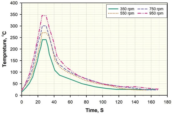
Figure 8.
Represents the temperature progression experienced by AA6082-T6 FSSW joints processed at different rotational speeds of 350, 550, 750, and 950 rpm and a fixed dwell time of 5 s.
3.3. Macrostructure of the FSSW Joints
Figure 9 displays macroscopic cross-sections of AA6082-T6 FSSW joints, produced at tool rotation rates of 350, 550, 750, and 950 rpm, with a fixed welding time of 5 s. A notable observation from these macrographs is the creation of flawless spot-welds at the overlapping interface between the 1 mm and 2 mm AA6082-T6 Al alloys, indicating optimal FSSW conditions. The macrostructure of the friction stir spot welded joints of AA6082 aluminum alloys exhibits different zones caused by the localized heat and plastic deformation. These zones are: Base material (BM), stir zone (SZ), thermo-mechanically affected zone (TMAZ), and heat-affected zone (HAZ). Each zone has distinct features determined by the thermal cycle to which it was subjected [33,35]. A defining attribute of the fabricated spot welds is the presence of a unique central opening. This feature, known as a keyhole, is a consequence of the pin’s withdrawal and constitutes the most substantial defect in FSSW, representing localized material absence.
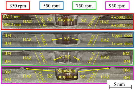
Figure 9.
Shows macrographs of the FSSW AA6082-T6 joints processed using various tool rotational speeds and a constant welding time of 5 s.
3.4. Results of Hardness and Tensile-Shear Tests of the AA6082-T6 FSSW Joints
Hardness measurement is an important factor in determining the mechanical performance and quality of FSSW joints, especially for lightweight high strength materials like AA6082-T6 aluminum alloy sheets. The FSSW process involves complex thermomechanical interactions that significantly influence the microstructure and, consequently, the hardness values across the weld zones (SZ, TMAZ, and HAZ). Analysis of the hardness profiles for the 1 mm and 2 mm thick AA6082-T6 alloy joints, processed at different rotational speeds (350, 550, 750, and 950 rpm) with a fixed welding time of 5 s (Figure 10), provides essential insights into how tool rotational speed affects on joint integrity
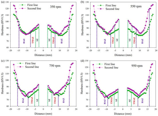
Figure 10.
Hardness profiles of the AA6082-T6 FSSW joints processed at (a) 350 rpm, (b) 550 rpm, (c) 750 rpm, and (d) 950 rpm tool rotational speeds and a fixed welding time of 5 s.
Such investigations are vital for optimizing welding parameters, ensuring structural reliability, and expanding the potential applications of FSSW in demanding engineering fields. The mean hardness values of the AA6082-T6 alloy sheets are 110 ± 4 and 125 ± 5 HV0.3 for the 2 mm and 1 mm sheets, respectively. From Figure 10, it is evident that the hardness values in the weld zones of the produced joints decreased significantly under all applied FSSW conditions compared to the base materials (BMs) of the 1 mm and 2 mm AA6082-T6 sheet alloys. This hardness loss is ascribed to the annealing effect on the AA6082-T6 BMs, a phenomenon caused by the heat produced during FSSW [53]. The hardness of the distinct zones within the FSSW lap-joints (SZ, TMAZ, and HAZ) is governed by the introduced heat-input and the initial state of the BM-T6 condition [22,54]. Accordingly, prolonged thermal influence is predicted to cause a reduction in hardness within the weld, stemming from either coarsening or dissolution of the hardening precipitates [55]. The SZ of all AA6082-T6 spot-lap joints, processed at different rotational speeds (350–950 rpm), consistently displayed peak hardness values. This phenomenon is attributed to the formation of dynamically recrystallized equiaxed fine grains and the reprecipitation of phases during the cooling cycle [5,17]. The HAZ, however, registered the lowest hardness, a consequence of both its grain morphology and over-aging phenomena [15,17]. The TMAZ displayed intermediate hardness values, being lower than the SZ but higher than the HAZ. Based on the recorded hardness measurements in Figure 10, it can be concluded that the hardness of the joint processed at the tool rotational speed of 550 rpm shows higher values than the remain joints processed at 350, 750 and 950 rpm. The maximum hardness measurements were 94.6 ± 1.4, 88 ± 2, and 82 ± 1.4 HV0.3 for the SZ, TMAZ, and HAZ, respectively, of the FSSW joint produced at 550 rpm (Figure 10b).
The tensile-shear test is a fundamental mechanical evaluation used to assess the load-bearing capacity and deformation behavior of the FSSW AA6082-T6 aluminum lap-joints. This test provides critical insights into the joint’s structural integrity and mechanical performance under shear stress. Figure 11 shows the tensile-shear load of the FSSW joints at different welding conditions versus the elongation value in mm. These values represent the cross-head displacement of the testing machine, which, while an indirect measure, is used to establish a valid comparative trend of the deformation behavior across all samples tested under identical conditions. Among all spot-jointed specimens, the FSSW joints welded at 550 rpm and 5 s had the highest joint quality in terms of both tensile-shear load and elongation compared to the other joints processed at 350, 750, and 950 rpm for the same welding time. The maximum tensile-shear load for the AA6082-T6 FSSW joints varied according to the welding conditions of each joint, showing a close relationship with the tool’s rotational speed, while the welding time remained fixed at 5 s. The maximum tensile-shear loads were as follows: 3.57 ± 0.25, 4.73 ± 0.27, 3.92 ± 0.22, and 2.97 ± 0.20 kN for the joints welded at the rotational speeds of 350, 550, 750 and 950 rpm, respectively, as shown in Figure 12.
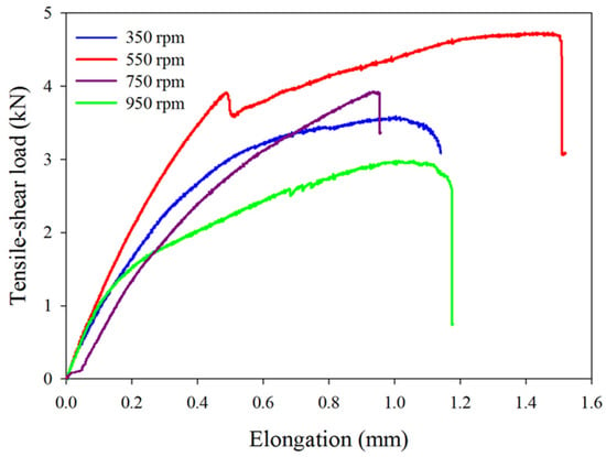
Figure 11.
Represents the tensile-shear load versus elongation of the produced FSSW joints at different processed at different tool rotational speeds (350–950 rpm) and a constant dwell time of 5 s.
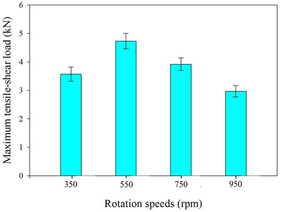
Figure 12.
Shows the maximum tensile-shear load values of the AA6082-T6 joints welded different rotational speeds (350–950 rpm) and a dwell time fixed at 5 s.
The thermal history during the FSSW process has a direct influence on the final mechanical properties and microstructure of the joint. The highest peak temperatures generated at 750 and 950 rpm led to significant thermal softening, which is reflected in lower hardness values and reduced maximum tensile-shear loads of 3.92 ± 0.22 kN and 2.97 ± 0.20 kN, respectively. Conversely, the moderate peak temperature of 269 °C at the optimal 550 rpm condition created a balanced thermomechanical environment. This condition was sufficient to promote dynamic recrystallization, resulting in a fine-grained microstructure within the SZ, and avoiding the negative effects of excessive heat input. This optimal balance directly contributes to the peak hardness of 94.6 ± 1.4 HV0.3 and the highest tensile-shear load of 4.73 ± 0.27 kN observed in these joints.
The experimental results demonstrate a clear relationship between tool rotational speed, joint geometry, and the resulting tensile-shear load. The initial stiffness, represented by the slope of the elastic region, indicates the quality and size of the bonded area. This optimal performance at 550 rpm can be directly correlated with the measured bonded area and hook height for the joint. As the rotational speed increased from 350 rpm to 950 rpm, the bonded area also continuously increased, from 113.04 mm2 to 214.90 mm2. Simultaneously, the hook height increased from 0.15 mm to 0.38 mm. The observed peak in tensile-shear load at 550 rpm, with a bonded area of 132.63 mm2 and a hook height of 0.32 mm, represents an optimal balance between these two competing factors. At lower speeds (350 rpm), the lower tensile-shear load (3.57 ± 0.25 kN) is primarily attributed to an insufficient bonded area. Conversely, at higher speeds (750 and 950 rpm), while the bonded area continues to increase, the tensile-shear load decreases significantly to 3.92 ± 0.22 kN and 2.97 ± 0.20 kN, respectively. The abrupt load drops observed in these joints are a direct result of stress concentration at the keyhole defect, which acts as a primary fracture initiation point. This decline is likely due to the negative influence of the higher hook height, which can act as a stress concentration point, and other potential defects related to excessive material flow. Therefore, the 550-rpm welding condition provides the most favorable combination of a sufficiently large bonded area and a controlled hook height, leading to superior mechanical properties.
3.5. Fracture Location and Morphology
The macro-fracture locations and features of the tensile-shear test specimens of the FSSW joints provide critical insights into the joint performance of the aluminum alloy sheets at varying welding conditions [5,17]. For the AA6082-T6 lap-joints of 1 mm and 2 mm sheet materials, the fracture characteristics differ based on the welding conditions, particularly the tool rotational speed, as the welding time is constant. At a low tool rotational speed of 350 rpm, insufficient heat generation leads to weak bonding between the two sheets. Macro images of the fracture surfaces show uneven plastic deformation and a notable lack of complete material mixing in the SZ (Figure 13). Fractures tend to initiate at the sheet interface, propagating along the weakly bonded regions, which results in a relatively low load-carrying capacity compared to the moderate heat inputs at the tool rotational speeds of 550 and 750 rpm (Figure 12). At 550 rpm, the weld joint exhibits the most uniform and consistent bonding, leading to high joint performance. A portion of the spot-joint remains connected after the tensile-shear test (Figure 13), indicating a high joint load-carrying capacity. Fractures typically initiate at the edge of the SZ, suggesting an optimal balance between heat generation and material deformation. The improvement in tensile-shear load-carrying capacity is attributed to a larger fully bonded area and an optimal hook height [17,56]. At the highest rotational speed (950 rpm), the introduced heat input leads to potential softening of the weld zone, which causes decreasing in the maximum tensile shear load (Figure 12). Macro features include excessive thinning near the upper sheet and flash formation. Fractures are dominated by necking in the upper sheet due to localized softening.
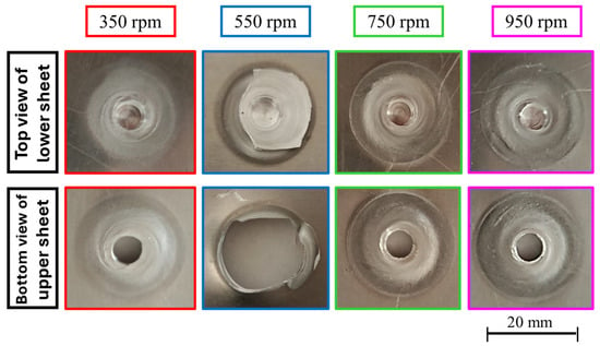
Figure 13.
Presents photographs showing top view and bottom view morphologies the fracture surfaces of the AA6082-T6 FSSW lap-joints welded at varying tool rotational speeds (350–550) and a fixed welding time of 5 s.
Figure 14 provides insight into the fracture behavior of the AA6082-T6 alloy BMs. Two primary fracture types, ductile and brittle, are observed for the 1 mm (Figure 14a,b) and 2 mm (Figure 14c,d) sheet thicknesses. The ductile fracture is confirmed by the dimpled texture of the aluminum matrix, with dimples varying in size on the 1 mm sheet and appearing shallow and elongated on the 2 mm sheet. In contrast, brittle fracture is characterized by the presence of precipitate phases of Mg2 Si and (Fe, Mn)3 SiAll2 which were identified using Energy-Dispersive X-ray Spectroscopy (EDS) point analysis (Figure 15, Spots 1 and 2, respectively). The large second phases visible on the fracture surfaces are these brittle intermetallic compounds, specifically (Fe, Mn)3 SiAll2 particles, which act as stress concentration sites. Under tensile loading, fracture initiates either by the cracking of these particles themselves or by decohesion at the particle-matrix interface. Microcracks and microvoids are also detected upon examining the two alloy fracture surfaces. These are due to microvoid coalescence and precipitates pullout, respectively. These findings are in agreement with those identified in other works [33,54].
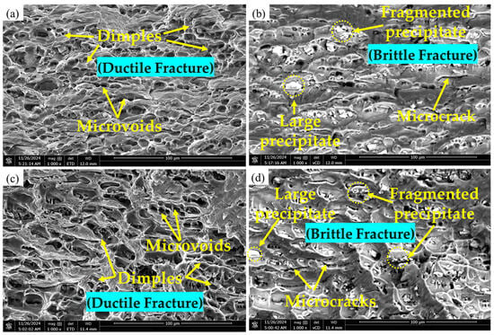
Figure 14.
Displays SEM images, captured with different detectors (ETD and vCD), detailing the fracture surfaces of the AA6082-T6 BMs. The morphology is compared for (a,b) 1 mm and (c,d) 2 mm alloy thicknesses.
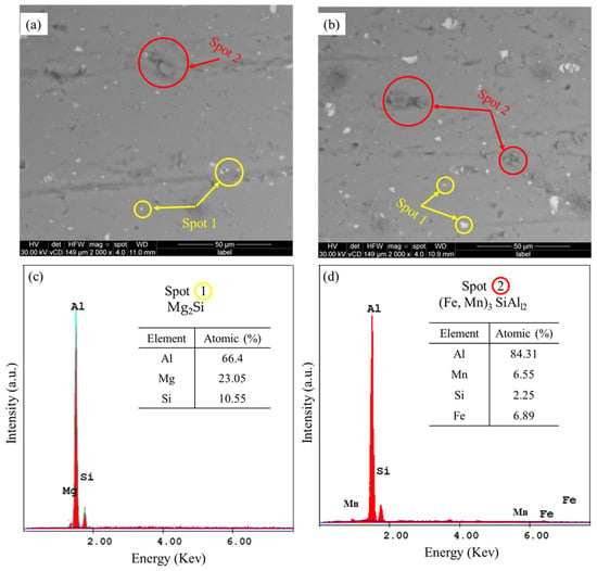
Figure 15.
(a,b) SEM images of AA6082-T6 BMs and (c,d) EDS point analyses of the detected precipitates for the 1 mm and 2 mm sheet thicknesses, respectively.
Figure 16 shows SEM images of the fracture surfaces (after tensile-shear testing) of the lower sheets of the FSSW joints. These joints were welded at various rotational speeds: 350 rpm (Figure 16a,b), 550 rpm (Figure 16c,d), 750 rpm (Figure 16e,f) and 950 rpm (Figure 16g,h), with a constant welding time of 5 s. Failure in all FSSW lap joints occurred due to a tensile-shear mechanism. During the application of tensile-shear loads, microcracks commonly began at the hook’s tip, specifically in areas with incomplete bonding. These cracks then primarily advanced along the horizontal plane at the joint’s interface, shearing the SZ and causing failure. The time to failure and the load-carrying capacity of the spot-joined materials depend mainly on the joining heat input in terms of tool rotational speed when the welding time is constant.
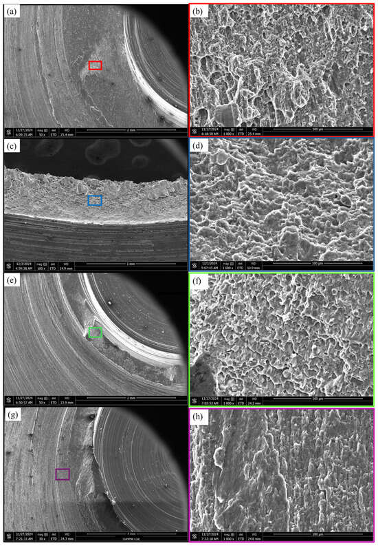
Figure 16.
SEM-images (Low and high magnifications) of the fracture surfaces of the lower sheets of the FSSW joints produced at varies rotational speeds of 350 (a,b), 550 (c,d), 750 (e,f) and 950 rpm (g,h) and a constant welding time of 5 s.
The analyzed fracture surfaces consistently displayed predominant ductile characteristics, evidenced by the presence of small, deep dimples. A partially brittle fracture mode, marked by fragmented precipitates, was also observed. These findings suggest significant grain refinement within the SZ during FSSW when compared to the elongated dimples and large precipitates in the two AA6082-T6 alloy BMs [57]. For the suggested welding parameters in the present work and based on the results of hardness measurements (Figure 10), the tensile-shear test findings (Figure 11 and Figure 12), and the macro and micro examinations of the fracture surfaces in Figure 13 and Figure 16, respectively, it can be concluded that the best condition to join a 1 mm sheet of AA6082-T6 on a 2 mm sheet of AA6082-T6 via the conventional FSSW technique is 550 rpm and 5 s to attain the highest value of the joint performance.
Based on the above findings, the next sections of the current study will concentrate on addressing the keyhole defect in the FSSW AA6082-T6 joint produced under the optimal welding conditions for 1 mm and 2 mm sheet thicknesses (i.e., 550 rpm and 5 s). This will be achieved by implementing a friction stir deposition (FSD) technique to create continuous multi-layers of the same alloy (AA6082-T6), thereby eliminating the defect and enhancing the joint efficiency. A comparative analysis will be conducted between joints with the keyhole defect and those refilled using the FSD technique, focusing on macrostructure, microstructure, hardness and tensile-shear test results.
3.6. Macro, Microstructures and EBSD of the FSSW and the Refilled Joints
Figure 17a,b illustrations the macrostructures of the AA6082-T6 FSSW joint (Figure 17a) and its refilled joint (Figure 17b). Both joints were FSSW at the same condition of 500 rpm and 5 s, while the keyhole repair was achieved via refilling process utilizing a FSD technique to build continuous malti-layers of AA6082-T6. Based on some trail experiments and pervious work [38], the deposition parameters were established as 450 rpm and 1 mm/min. It should be noted that this approach enabled effective keyhole repair using the identical AA6082-T6 alloy and the deposited continuous malti-layers exhibited excellent adhesion to the keyhole’s inner surface. This leads the absence of porosity or microcracks in the final produced joint. The controlled refilling process deposits AA6082-T6 material that exceeds the keyhole cavity height by 0.3–0.5 mm, ensuring complete defect elimination. Quantitative analysis of the refilled zone confirms effective keyhole remediation, with cross-sectional examination revealing a sound weld joint containing minimal residual burr. The automated deposition control system maintains consistent refill quality while preventing excessive material accumulation.
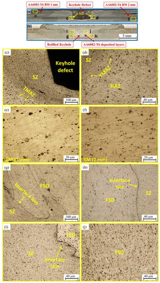
Figure 17.
Macrostructures of the (a) AA6082-T6 FSSW joint and (b) its refilled joint both were FSSW at 550 rpm and 5 s. The FSD of AA6082-T6 refilling process achieved at 450 rpm and 1 mm/min. (c–f) OM microstructures of the FSSW joint and (g–j) OM microstructures of the refilled joint.
Figure 17c–f represents the microstructure features of SZ, TMAZ, HAZ and base materials (1 mm AA6082-T6 and 2 mm AA6082-T6), While Figure 17g,j depicts the microstructures observed in different areas of the deposited AA6082-T6 material. The main structural features of the FSSW zones are dynamic recrystallization fine, equiaxed grains in the SZ (Figure 17c) due to the severe plastic deformation and thermal cycle effects. The grain size in the SZ is smaller than that found in the 1 mm and 2 mm BM sheets, contributing to localized strengthening. The OM-images of the TMAZ (Figure 17d) shows elongated and distorted grains (Figure 17c,d) due to mechanical stirring and moderate thermal input, whereas relatively coarser grains compared to the SZ and base material are detected in the HAZ due to thermal cycle exposure during the FSSW process. Both the BM alloys microstructure images (Figure 17e,f) show elongated grains in the direction of the rolling process; besides, the presence of Mg2Si precipitates enhance the mechanical properties of the BMs. Totally, these gained microstructure features for the cross-sections of the AA6082-T6 FSSW zones are in good agreement with that mentioned by different authors in different works [33,35,43].
The EBSD IPF coloring maps provide valuable insights into the microstructural evolution in the SZ and FSD layers of AA6082-T6 joints as given in Figure 18. Both the SZ of FSSW (Figure 18a) and the friction stir deposited layers (Figure 18c) in the refilled FSSW joints exhibit fine, equiaxed grains resulting from dynamic recrystallization due to severe plastic deformation and elevated temperatures as a result of stirring action during FSSW [5,17,56] and FSD [38] processes. The average grain size of the 1 mm AA6082-T6 and 2 mm AA6082-T6 BMs were 8.6 ± 0.7 (Figure 17e) and 9.76 ± 1.6 (Figure 17f), respectively. These values decreased to be 5.05 ± 0.09 in the SZ of the AA6982-T joint spot welded at 550 rpm and 5 s (Figure 18b), demonstrating substantial grain refinement as a result of the spot-welding process. Also, filling the keyhole defect with continuous layers of the same alloy using a technique that gives a smaller grain size of 7.80 ± 0.1 (Figure 18d) than the base material gives high mechanical properties to the spot welded joint, according to the Hall-Pitch relationship, the smaller the particle size, the higher the strength [58]. So, it can be said that the refilled FSSW joints, with their improved grain structure demonstrate superior mechanical properties compared to the conventional FSSW joints, highlighting the effectiveness of the FSD process in addressing keyhole defects.
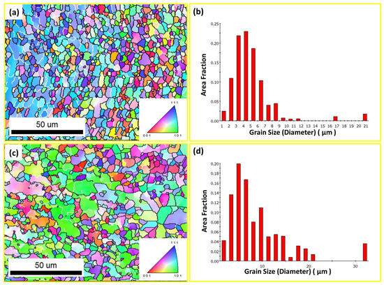
Figure 18.
Inverse pole figure (IPF) coloring maps and grain size histogram of (a,b) SZ of the FSSW joint and (c,d) the deposited layers of the refilled FSSW joint, respectively.
The FSSW and FSD technologies are based on the principles of friction stir welding, and are considered forms of friction stir processing. In these processes, the initial material is subjected to a severe plastic deformation accompanied by the frictional heat. In most cases these techniques promote dynamic recrystallization and formation of equiaxed fine grains at the expense of the original elongated grain structure associated with rolling in the case of sheets or extrusion in the case of rods [39,59]. Two areas were selected, one of which was in the SZ of the FSSW joint, which gave the best mechanical properties, and one in the keyhole refilled zone (AA6082-T6 friction stir deposited layers) to be investigated using EBSD. The EBSD obtained results are given in terms of Inverse pole figure (IPF) coloring maps (Figure 18a,c) and grain size histograms (Figure 18b,d). It is observed that for both regions the average grain size is somewhat close, between 5.05 µm and 8.80 µm for the SZ and FSD zone, respectively. This slight difference in average grain size may due to the different of initial forming conditions the BM in terms of whether it is a AA6082-T6 sheet or a rod, and/or also due to the difference in the amount of heat input generated by the treatment with friction stir process. However, the main feature is the participation in the occurrence of dynamic recrystallization, which results in a relative improvement in the quality of the joint and the homogeneity of the spot-welding area as a whole. This was clearly shown in the following mechanical measurements.
3.7. Hardness and Tensile-Shear Results
In the FSSW AA6082-T6 lap joints processed at 550 rpm and 5 s dwell time, the hardness map distribution across the cross-section typically exhibits different areas with different colors indicating different hardness values measured as shown in Figure 19. These colored areas represent the SZ, TMAZ, HAZ and BM. The BM maintains the highest hardness as it retains its original T6 temper microstructure with uniformly distributed precipitates. The hardness in the SZ is generally lower than the base material (BM) due to thermal softening and dissolution of strengthening precipitates (e.g., Mg2Si) caused by the high heat input [35,54]. The TMAZ shows a gradual decrease in hardness as it transitions from the SZ to the HAZ. This is due to partial grain deformation and precipitate coarsening without complete recrystallization. The HAZ exhibits the lowest hardness in the joint depend on the thermal exposure duration.
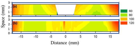
Figure 19.
Vickers hardness maps of the cross-section specimens of the (a) AA6082-T6 FSSW and (b) the refilled FSSW joints welded at 550 rpm and 5 s. The refilling achieved using AA6082-T6 rod via the FSD process at 450 rpm and 1 mm/min.
When the keyhole is refilled using a consumable AA6082-T6 rod at 450 rpm and a feed rate of 1 mm/min, the hardness contour map reveals some features, as give in Figure 19. The main features of the refilled joint cross-section are different from those of a conventional FSSW cross-section in terms of the disappearance of the keyhole defect, resulting in a sound weld joint at the cross-sectional level. The deposited layers also showed a homogeneous distribution of hardness contour maps, and there is an improvement in the hardness of the adjacent zones (SZ, TMAZ, and HAZ). The AA6082-T6 deposited zone shows an increase in hardness compared to the original SZ with a slight hardness gradient at the interface due to the thermal and mechanical effects of the deposition process. The metallurgical bonding between the deposited material and the original SZ enhances overall joint integrity. For the TMAZ and HAZ, the hardness profile in these regions remains similar to the original FSSW joint, with some minor recovery in the HAZ due to re-heating during the deposition process. In fact, the hardness contour maps highlight the benefits of refilling the AA6082-T6 FSSW joint, particularly in enhancing the hardness of the SZ and eliminating weak zones associated with the keyhole defect. This improvement contributes to higher joint efficiency, making the refilled FSSW approach a viable solution for improving the mechanical performance of the FSSW lap joints in aluminum alloys. This is clearly shown in the tensile-shear curves of both FSSW joints in the presence of the keyhole and when this hole is filled with CMFSD of AA6082-T6 alloy, as illustrated in Figure 20. The tensile-shear curve for the AA6082-T6 FSSW lap joint welded at 550 rpm and 5 s typically shows an initial elastic region followed by plastic deformation, reaching a peak load (4.73 ± 0.27 kN) that represents the joint’s maximum tensile-shear strength. Beyond the peak load, a sudden drop in load is noticed, indicating failure. The overall elongation is relatively limited due to the keyhole defect, which represents a loss in the connection of the welding area and may act as a stress concentrator, causing a reduction in the joint’s capacity to sustain plastic deformation. While, the tensile-shear curve for the refilled AA6082-T6 lap-joint FSSW at the same condition and refilled via the FSD using AA6082-T6 rod material at 450 rpm and feeding rate of 1 mm/min exhibits a more extended plastic region compared to the original FSSW joints. The maximum tensile-shear load (6.93 ± 0.19 kN) of the refilled FSSW is higher than that of the FSSW joint due to the elimination of the keyhole defect and improved bonding from the friction stir deposition (FSD) process. The elongation to failure is significantly increased, indicating enhanced ductility and energy absorption capacity of the refilled joint. The noticeably reduced stiffness of the refilled joint (Figure 20) likely stems from residual stresses or microstructural gradients at the deposition interface, which significantly affect initial elastic resistance. However, this effect is counterbalanced by the the refined grain structure and keyhole elimination, which collectively enable both higher peak strength and substantially prolonged plastic deformation.
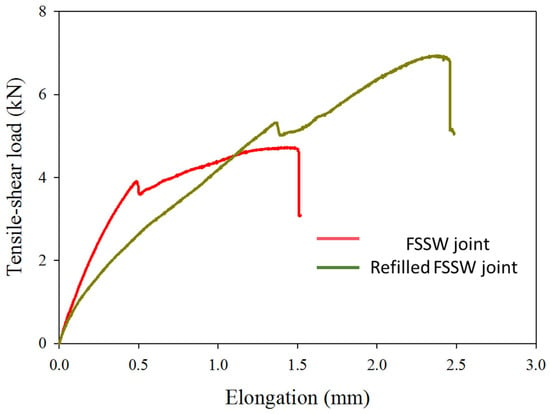
Figure 20.
Tensile-shear curves of the AA6082-T6 FSSW and the refilled joints both were FSSW at 550 rpm and 5 s. The refilling process achieved using AA6082-T6 rod via the FSD process at 450 rpm and a feeding rate of 1 mm/min.
It is noted that the refilled-FSSW joint fabricated at 550 and for 5 s and keyhole refilled via FSD of AA6082-T6 consumable rod at 450 rpm and feeding rate of 1 mm/min gives superior joint performance over that only FSSW at the same condition. After the sample was subjected to the tensile-shear test, the FSSW and filling zones resisted the applied load and a fracture occurred in the upper sheet of 1 mm (Figure 21a), which indicates that the welding area after repairing the keyhole area became stronger than the upper 1 mm sheet thickness in load carrying capacity. The refilled joint’s mechanical performance is influenced by the deposited material’s thickness, which exceeds the keyhole depth by 0.3–0.5 mm to ensure complete defect elimination. This overfilling strengthens the joint, as evidenced by fracture occurring in the 1 mm base sheet (not the refilled zone), confirming the deposited material’s superior load-bearing capacity. While quantitative thickness-strength correlations could further validate these findings, the current results demonstrate that the overfilled design mitigates stress concentration and promotes ductile failure in the parent material.
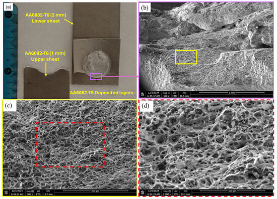
Figure 21.
Shows (a) a photo-image of the AA6082-T6 separated parts after tensile-shear testing of the refilled FSSW joint welded at 550 rpm and 5 s and the keyhole refilling achieved at 450 rpm and 1 mm/min, (b–d) SEM-images at different magnifications.
It is also noted that the characteristics of the fracture surface of the AA6082-T6 deposited layers of the refilled FSSW joint, as given in Figure 21b–d, do not differ in general from the characteristics of the fracture surface of the SZ of the FSSW joint spot welded under the same conditions without filling the keyhole (Figure 16c,d). This similarity may be a result of the keyhole filling zone, which is the AA6082-T6 deposited layers, being similar in chemical composition to the primary spot-welded zone (SZ of the AA6082-T6 FSSW joint). Both of them resulted from a friction stir processing process, which is exposure to a severe plastic deformation in the presence of heat, which led to similar changes in the microstructure of the BMs in terms of formation of dynamically recrystallized fine grain structures and fragmentation of the stable large size precipitates. Thus, the fracture surface shows similar features with a slight difference due to the difference in heat input in both cases. The difference in the morphology of the dimples may be due to the difference in the amount of heat input in the two cases, but they are completely identical in the existing phases due to the agreement in the chemical composition. The fracture surface of the investigated area shows a ductile fracture mode with some features of a brittle fracture mode for the hard precipitate phases.
4. Conclusions
- The selected FSSW conditions (tool rotational speeds of 350, 550, 750, and 950 rpm with a fixed 5 s dwell time) successfully produced spot lap joints between thin AA6082-T6 Al alloy sheets (1 mm upper sheet and 2 mm lower sheet).
- The FSSW joint produced at 550 rpm with 5 s dwell time demonstrated optimal performance, achieving both the highest SZ hardness (94.6 ± 1.4 HV0.3) and maximum tensile-shear load (4.73 ± 0.27 kN) among all tested parameters.
- The proposed FSD approach, including AA6082-T6 consumable tool design and set-tings, offers new possibilities for repairing the FSSW keyhole defects in various welding joints.
- The refilled FSSW joint exhibits a maximum tensile-shear load (6.93 ± 0.19 kN) higher than that of the FSSW joint (4.73 ± 0.27 kN) welded at the same FSSW condition due to the elimination of the keyhole defect and improved joining zone from the FSD process at 450 rpm and a feeding rate of 1 mm/min.
- The examined fracture surfaces of both the initial and keyhole-refilled FSSW joints showed a primary ductile fracture pattern in the aluminum matrix, distinguished by dimples of diverse sizes and depths. Additionally, a secondary, partially brittle fracture mechanism was identified through the fragmentation and pull-out of stable precipitates.
- The EBSD investigation of the SZ of the traditional FSSW joint and the deposited con-tenuous multi-layers of the refilled keyhole joint welded at the conditions (550 rpm and 5 s) showed dynamically recrystallized refined grain size. For both regions, the aver-age grain size is somewhat close, between 5.05 µm and 8.80 µm for the SZ and FSD zone, respectively. This slight difference in average grain size may due to the difference in initial forming conditions of the BM in terms of whether it is a AA6082-T6 sheet or a rod, and/or also due to the difference in the amount of heat input generated by the treatment with friction stir process.
- This work opens the way for researchers and welders to address friction stir welding faults such as the keyhole, a non-contact region in the joint that decreases the maximum load carrying capacity and ductility.
5. Future Work
Future work will focus on a comprehensive fatigue performance evaluation of both conventional FSSW and keyhole-refilled FSSW joints in AA6082-T6 under cyclic loading, including detailed fractographic analysis to understand failure mechanisms. Additionally, investigations into the corrosion behavior of these refilled joints and further optimization of the continuous multi-layer friction stir deposition (CMFSD) process parameters are planned to enhance their industrial applicability.
Author Contributions
Conceptualization, M.M.Z.A., M.M.E.-S.S., B.A., A.B. and A.A.; methodology, A.B., M.M.E.-S.S. and M.M.Z.A.; software, B.A. and A.A.E.-A.; validation, A.A. and A.B.; formal analysis, B.A. and M.M.E.-S.S.; investigation, B.A., A.A., A.A.E.-A. and A.B.; resources, M.M.Z.A. and B.A.; data curation, A.A.E.-A. and B.A.; writing—original draft preparation, M.M.Z.A., A.B. and M.M.E.-S.S. writing—review and editing, M.M.E.-S.S.; visualization, A.A. and A.A.E.-A.; supervision, M.M.E.-S.S., A.B. and M.M.Z.A.; project administration, B.A. and M.M.Z.A.; funding acquisition, B.A. and M.M.Z.A. All authors have read and agreed to the published version of the manuscript.
Funding
The authors extend their appreciation to Prince Sattam bin Abdulaziz University for funding this research work through the project number (PSAU/2024/01/28387).
Data Availability Statement
The original contributions presented in this study are included in the article. Further inquiries can be directed to the corresponding author.
Acknowledgments
The authors are grateful to Prince Sattam bin Abdulaziz University for funding this research work through the project number (PSAU/2024/01/28387).
Conflicts of Interest
The authors declare no conflicts of interest.
References
- Jambhale, S.; Kumar, S.; Kumar, S. Characterization and Optimization of Flat Friction Stir Spot Welding of Triple Sheet Dissimilar Aluminium Alloy Joints. Silicon 2022, 14, 815–830. [Google Scholar] [CrossRef]
- Ibrahim, I.J.; Yapici, G.G. Application of a Novel Friction Stir Spot Welding Process on Dissimilar Aluminum Joints. J. Manuf. Process 2018, 35, 282–288. [Google Scholar] [CrossRef]
- Reimann, M.; Gartner, T.; Suhuddin, U.; Göbel, J.; Dos Santos, J.F. Keyhole Closure Using Friction Spot Welding in Aluminum Alloy 6061-T6. J. Mater. Process Technol. 2016, 237, 12–18. [Google Scholar] [CrossRef]
- Ilman, M.N. Microstructure and Mechanical Performance of Dissimilar Friction Stir Spot Welded AA2024-O/AA6061-T6 Sheets: Effects of Tool Rotation Speed and Pin Geometry. Int. J. Lightweight Mater. Manuf. 2023, 6, 1–14. [Google Scholar] [CrossRef]
- Ahmed, M.M.Z.; El-Sayed Seleman, M.M.; Sobih, A.M.E.S.; Bakkar, A.; Albaijan, I.; Touileb, K.; Abd El-Aty, A. Friction Stir-Spot Welding of AA5052-H32 Alloy Sheets: Effects of Dwell Time on Mechanical Properties and Microstructural Evolution. Materials 2023, 16, 2818. [Google Scholar] [CrossRef]
- Cao, J.Y.; Wang, M.; Kong, L.; Zhao, H.X.; Chai, P. Microstructure, Texture and Mechanical Properties during Refill Friction Stir Spot Welding of 6061-T6 Alloy. Mater. Charact. 2017, 128, 54–62. [Google Scholar] [CrossRef]
- Pang, Q.; Zhang, J.H.; Huq, M.J.; Hu, Z.L. Characterization of Microstructure, Mechanical Properties and Formability for Thermomechanical Treatment of Friction Stir Welded 2024-O Alloys. Mater. Sci. Eng. A 2019, 765, 138303. [Google Scholar] [CrossRef]
- Ahmed, M.M.Z.; Jouini, N.; Alzahrani, B.; Seleman, M.M.E.S.; Jhaheen, M. Dissimilar Friction Stir Welding of AA2024 and AISI 1018: Microstructure and Mechanical Properties. Metals 2021, 11, 330. [Google Scholar] [CrossRef]
- Zhang, B.; Chen, X.; Pan, K.; Wang, J. Multi-Objective Optimization of Friction Stir Spot-Welded Parameters on Aluminum Alloy Sheets Based on Automotive Joint Loads. Metals 2019, 9, 520. [Google Scholar] [CrossRef]
- Çam, G.; Ipekoğlu, G.; Tarık Serindağ, H. Effects of Use of Higher Strength Interlayer and External Cooling on Properties of Friction Stir Welded AA6061-T6 Joints. Sci. Technol. Weld. Join. 2014, 19, 715–720. [Google Scholar] [CrossRef]
- Shen, J.; Lage, S.B.M.; Suhuddin, U.F.H.; Bolfarini, C.; dos Santos, J.F. Texture Development and Material Flow Behavior During Refill Friction Stir Spot Welding of AlMgSc. Met. Mater. Trans. A Phys. Met. Mater. Sci. 2018, 49, 241–254. [Google Scholar] [CrossRef]
- Khalaf, H.I.; Al-Sabur, R.; Derazkola, H.A. Effect of Number of Tool Shoulders on the Quality of Steel to Magnesium Alloy Dissimilar Friction Stir Welds. Arch. Civ. Mech. Eng. 2023, 23, 125. [Google Scholar] [CrossRef]
- Singh Sekhon, S.; Kumar, H.; Sehgal, S. Effect of Tool Pin Profile on Performance of Friction Stir Welding of Brass-Copper-Based Butt Welded Joint. Int. J. Mater. Eng. Innov. 2016, 7, 236–252. [Google Scholar] [CrossRef]
- Chanakyan, C.; Sivasankar, S.; Meignanamoorthy, M.; Ravichandran, M.; Mohanavel, V.; Alfarraj, S.; Almoallim, H.S.; Manikandan, V.; Isaac Joshuaramesh Lalvani, J. Optimization of FSP Process Parameters on AA5052 Employing the S/N Ratio and ANOVA Method. Adv. Mater. Sci. Eng. 2021, 2021, 6450251. [Google Scholar] [CrossRef]
- Tiwan; Ilman, M.N.; Kusmono. Microstructure and Mechanical Properties of Friction Stir Spot Welded AA5052-H112 Aluminum Alloy. Heliyon 2021, 7, e06009. [Google Scholar] [CrossRef]
- Lin, Y.C.; Chen, J.N. Influence of Process Parameters on Friction Stir Spot Welded Aluminum Joints by Various Threaded Tools. J. Mater. Process Technol. 2015, 225, 347–356. [Google Scholar] [CrossRef]
- Ahmed, M.M.Z.; El-Sayed Seleman, M.M.; Albaijan, I.; Abd El-Aty, A. Microstructure, Texture, and Mechanical Properties of Friction Stir Spot-Welded AA5052-H32: Influence of Tool Rotation Rate. Materials 2023, 16, 423. [Google Scholar] [CrossRef]
- Zhao, Y.Q.; Liu, H.J.; Chen, S.X.; Lin, Z.; Hou, J.C. Effects of Sleeve Plunge Depth on Microstructures and Mechanical Properties of Friction Spot Welded Alclad 7B04-T74 Aluminum Alloy. Mater. Des. 2014, 62, 40–46. [Google Scholar] [CrossRef]
- Rana, P.K.; Narayanan, R.G.; Kailas, S.V. Friction Stir Spot Welding of AA5052-H32/HDPE/AA5052-H32 Sandwich Sheets at Varying Plunge Speeds. Thin-Walled Struct. 2019, 138, 415–429. [Google Scholar] [CrossRef]
- Di Bella, G.; Favaloro, F.; Borsellino, C. Effect of Process Parameters on Friction Stir Welded Joints between Dissimilar Aluminum Alloys: A Review. Metals 2023, 13, 1176. [Google Scholar] [CrossRef]
- Sekhar, S.R.; Chittaranjandas, V.; Govardhan, D.; Karthikeyan, R. Effect of Tool Rotational Speed on Friction Stir Spot Welded AA5052-H38 Aluminum Alloy. In Materials Today: Proceedings; Elsevier Ltd.: Amsterdam, The Netherlands, 2018; Volume 5, pp. 5536–5543. [Google Scholar]
- Atak, A.; Şık, A.; Özdemir, V. Thermo-Mechanical Modeling of Friction Stir Spot Welding and Numerical Solution with The Finite Element Method. Int. J. Eng. Appl. Sci. (IJEAS) 2018, 5, 70–75. [Google Scholar]
- Ji, S.; Meng, X.; Zeng, Y.; Ma, L.; Gao, S. New Technique for Eliminating Keyhole by Active-Passive Filling Friction Stir Repairing. Mater. Des. 2016, 97, 175–182. [Google Scholar] [CrossRef]
- Rashkovets, M.; Dell’Avvocato, G.; Contuzzi, N.; Palumbo, D.; Galietti, U.; Casalino, G. On the Role of Rotational Speed in P-FSSW Dissimilar Aluminum Alloys Lap Weld. Weld. World 2025, 69, 2095–2107. [Google Scholar] [CrossRef]
- Ikumapayi, O.M.; Akinlabi, E.T. Recent Advances In Keyhole Defects Repairs via Refilling Friction Stir Spot Welding. In Materials Today: Proceedings; Elsevier Ltd.: Amsterdam, The Netherlands, 2019; Volume 18. [Google Scholar]
- Shi, Y.; Yue, Y.; Zhang, L.; Ji, S.; Wang, Y. Refill Friction Stir Spot Welding of 2198-T8 Aluminum Alloy. Trans. Indian Inst. Met. 2018, 71, 139–145. [Google Scholar] [CrossRef]
- Xu, Z.; Li, Z.; Ji, S.; Zhang, L. Refill Friction Stir Spot Welding of 5083-O Aluminum Alloy. J. Mater. Sci. Technol. 2018, 34, 878–885. [Google Scholar] [CrossRef]
- de Castro, C.C.; Plaine, A.H.; Dias, G.P.; de Alcântara, N.G.; dos Santos, J.F. Investigation of Geometrical Features on Mechanical Properties of AA2198 Refill Friction Stir Spot Welds. J. Manuf. Process 2018, 36, 330–339. [Google Scholar] [CrossRef]
- Lunetto, V.; Basile, D.; Razza, V.; Russo Spena, P. Active and Passive Filling Stir Repairing of AISI 304 Alloy. Metals 2024, 14, 911. [Google Scholar] [CrossRef]
- Deng, L.; Li, S.; Ke, L.; Liu, J.; Kang, J. Microstructure and Fracture Behavior of Refill Friction Stir Spot Welded Joints of AA2024 Using a Novel Refill Technique. Metals 2019, 9, 286. [Google Scholar] [CrossRef]
- Feng, X.S.; Li, S.B.; Tang, L.N.; Wang, H.M. Refill Friction Stir Spot Welding of Similar and Dissimilar Alloys: A Review. Acta Metall. Sin. (Engl. Lett.) 2020, 33, 30–42. [Google Scholar] [CrossRef]
- Muhayat, N.; Priatmana Putra, B.; Triyono; Suryanarayanan, R.; Sridhar, V.G. Effect of Process Parameters in Pinless Friction Stir Spot Welding of Al 5754-Al 6061 Alloys. Metallogr. Microstruct. Anal. 2020, 9, 01005. [Google Scholar] [CrossRef]
- Silva, B.H.; Zepon, G.; Bolfarini, C.; dos Santos, J.F. Refill Friction Stir Spot Welding of AA6082-T6 Alloy: Hook Defect Formation and Its Influence on the Mechanical Properties and Fracture Behavior. Mater. Sci. Eng. A 2020, 773, 138724. [Google Scholar] [CrossRef]
- Tier, M.D.; Rosendo, T.S.; Dos Santos, J.F.; Huber, N.; Mazzaferro, J.A.; Mazzaferro, C.P.; Strohaecker, T.R. The Influence of Refill FSSW Parameters on the Microstructure and Shear Strength of 5042 Aluminium Welds. J. Mater. Process Technol. 2013, 213, 997–1005. [Google Scholar] [CrossRef]
- Aydın, H.; Tunçel, O.; Tutar, M.; Bayram, A. Effect of Tool Pin Profile on the Hook Geometry and Mechanical Properties of a Friction Stir Spot Welded Aa6082-T6 Aluminum Alloy. Trans. Can. Soc. Mech. Eng. 2021, 45, 233–248. [Google Scholar] [CrossRef]
- Yuan, W.; Mishra, R.S.; Webb, S.; Chen, Y.L.; Carlson, B.; Herling, D.R.; Grant, G.J. Effect of Tool Design and Process Parameters on Properties of Al Alloy 6016 Friction Stir Spot Welds. J. Mater. Process Technol. 2011, 211, 972–977. [Google Scholar] [CrossRef]
- Buffa, G.; Fanelli, P.; Fratini, L.; Vivio, F. Influence of Joint Geometry on Micro and Macro Mechanical Properties of Friction Stir Spot Welded Joints. Procedia Eng. 2014, 81, 2086–2091. [Google Scholar] [CrossRef]
- Elfishawy, E.; Ahmed, M.M.Z.; El-Sayed Seleman, M.M. Additive Manufacturing of Aluminum Using Friction Stir Deposition. In TMS 2020 149th Annual Meeting & Exhibition Supplemental Proceedings; Minerals, Metals and Materials Series; Springer International Publishing: Berlin/Heidelberg, Germany, 2020; pp. 227–238. [Google Scholar]
- Elshaghoul, Y.G.Y.; El-Sayed Seleman, M.M.; Bakkar, A.; Elnekhaily, S.A.; Albaijan, I.; Ahmed, M.M.Z.; Abdel-Samad, A.; Reda, R. Additive Friction Stir Deposition of AA7075-T6 Alloy: Impact of Process Parameters on the Microstructures and Properties of the Continuously Deposited Multilayered Parts. Appl. Sci. 2023, 13, 10255. [Google Scholar] [CrossRef]
- Dong, H.; Li, X.; Xu, K.; Zang, Z.; Liu, X.; Zhang, Z.; Xiao, W.; Li, Y. A Review on Solid-State-Based Additive Friction Stir Deposition. Aerospace 2022, 9, 565. [Google Scholar] [CrossRef]
- Ahmed, M.M.Z.; El-Sayed Seleman, M.M.; Eid, R.G.; Zawrah, M.F. Production of AA1050/Silica Fume Composite by Bobbin Tool-Friction Stir Processing: Microstructure, Composition and Mechanical Properties. CIRP J. Manuf. Sci. Technol. 2022, 38, 801–812. [Google Scholar] [CrossRef]
- Singh, B.; Upadhyaya, R. Influence of Flat Friction Stir Spot Welding Process Parameters on Quality Characteristics of AA 6082 Weld. J. Univ. Shanghai Sci. Technol. 2021, 23, 123–133. [Google Scholar]
- Monajati, H.; Zoghlami, M.; Tongne, A.; Jahazi, M. Assessing Microstructure-Local Mechanical Properties in Friction Stir Welded 6082-T6 Aluminum Alloy. Metals 2020, 10, 1244. [Google Scholar] [CrossRef]
- Garg, A.; Bhattacharya, A. Strength and Failure Analysis of Similar and Dissimilar Friction Stir Spot Welds: Influence of Different Tools and Pin Geometries. Mater. Des. 2017, 127, 272–286. [Google Scholar] [CrossRef]
- Badarinarayan, H.; Yang, Q.; Zhu, S. Effect of Tool Geometry on Static Strength of Friction Stir Spot-Welded Aluminum Alloy. Int. J. Mach. Tools Manuf. 2009, 49, 142–148. [Google Scholar] [CrossRef]
- Hirasawa, S.; Badarinarayan, H.; Okamoto, K.; Tomimura, T.; Kawanami, T. Analysis of Effect of Tool Geometry on Plastic Flow during Friction Stir Spot Welding Using Particle Method. J. Mater. Process Technol. 2010, 210, 1455–1463. [Google Scholar] [CrossRef]
- Mehta, K.P.; Patel, R.; Vyas, H.; Memon, S.; Vilaça, P. Repairing of Exit-Hole in Dissimilar Al-Mg Friction Stir Welding: Process and Microstructural Pattern. Manuf. Lett. 2020, 23, 67–70. [Google Scholar] [CrossRef]
- Dilip, J.J.S.; Janaki Ram, G.D. Microstructure Evolution in Aluminum Alloy AA 2014 during Multi-Layer Friction Deposition. Mater. Charact. 2013, 86, 146–151. [Google Scholar] [CrossRef]
- Priedeman, J.L.; Phillips, B.J.; Lopez, J.J.; Tucker Roper, B.E.; Hornbuckle, B.C.; Darling, K.A.; Jordon, J.B.; Allison, P.G.; Thompson, G.B. Microstructure Development in Additive Friction Stir-Deposited Cu. Metals 2020, 10, 1538. [Google Scholar] [CrossRef]
- Joshi, S.S.; Patil, S.M.; Mazumder, S.; Sharma, S. Additive Friction Stir Deposition of AZ31B Magnesium Alloy. J. Magnes. Alloys 2022, 10, 2404–2420. [Google Scholar] [CrossRef]
- Zeng, X.H.; Xue, P.; Wu, L.H.; Ni, D.R.; Xiao, B.L.; Wang, K.S.; Ma, Z.Y. Microstructural Evolution of Aluminum Alloy during Friction Stir Welding under Different Tool Rotation Rates and Cooling Conditions. J. Mater. Sci. Technol. 2019, 35, 972–981. [Google Scholar] [CrossRef]
- Chen, C.-H.; Sun, Y.-K.; Lai, Y.-C.; Chang, S.-Y.; Chuang, T.-H. Effect of Post-Weld Heat Treatment on the Solid-State Diffusion Bonding of 6061 Aluminum Alloy. Appl. Sci. 2021, 11, 9660. [Google Scholar] [CrossRef]
- Suryanarayanan, R.; Sridhar, V.G. Studies on the Influence of Process Parameters in Friction Stir Spot Welded Joints—A Review. Mater. Today Proc. 2020, 37, 2695–2702. [Google Scholar] [CrossRef]
- Aydin, H.; Tuncel, O.; Umur, Y.; Tutar, M.; Bayram, A. Effect of Welding Parameters on Microstructure and Mechanical Properties of Aluminum Alloy AA6082-T6 Friction Stir Spot Welds. Indian J. Eng. Mater. Sci. 2017, 24, 215–227. [Google Scholar]
- Zhu, R.; Gong, W.B.; Cui, H. Temperature Evolution, Microstructure, and Properties of Friction Stir Welded Ultra-Thick 6082 Aluminum Alloy Joints. Int. J. Adv. Manuf. Technol. 2020, 108, 331–343. [Google Scholar] [CrossRef]
- Ataya, S.; Ahmed, M.M.Z.; El-Sayed Seleman, M.M.; Hajlaoui, K.; Latief, F.H.; Soliman, A.M.; Elshaghoul, Y.G.Y.; Habba, M.I.A. Effective Range of FSSW Parameters for High Load-Carrying Capacity of Dissimilar Steel A283M-C/Brass CuZn40 Joints. Materials 2022, 15, 1394. [Google Scholar] [CrossRef] [PubMed]
- Kumar, S.; Jambhale, S.; Maurya, M.; Kumar, S.; Pandey, S. Evaluation of Shear Force and Fractography of Friction Stir Spot Welded Joints of AA 6082-T6 Alloy. J. Eng. Res. 2022, 10, 124–144. [Google Scholar] [CrossRef]
- Cordero, Z.C.; Knight, B.E.; Schuh, C.A. Six Decades of the Hall–Petch Effect—A Survey of Grain-Size Strengthening Studies on Pure Metals. Int. Mater. Rev. 2016, 61, 495–512. [Google Scholar] [CrossRef]
- Rebrin, M.; Gester, A.; Ozherelkov, D.; Wächtler, C.; Sprigode, T.; Mädlow, M.; Wagner, G. Ultrasound-Enhanced Friction Stir Welding of Aluminum Alloy 6082: Advancements in Mechanical Properties and Microstructural Refinement. Metals 2024, 14, 1241. [Google Scholar] [CrossRef]
Disclaimer/Publisher’s Note: The statements, opinions and data contained in all publications are solely those of the individual author(s) and contributor(s) and not of MDPI and/or the editor(s). MDPI and/or the editor(s) disclaim responsibility for any injury to people or property resulting from any ideas, methods, instructions or products referred to in the content. |
© 2025 by the authors. Licensee MDPI, Basel, Switzerland. This article is an open access article distributed under the terms and conditions of the Creative Commons Attribution (CC BY) license (https://creativecommons.org/licenses/by/4.0/).