Abstract
This study systematically investigates the effects of welding current on the macro-morphology, microstructure, mechanical properties, and corrosion resistance of Cu-Mn-Al alloy coatings deposited on 27SiMn steel substrates using Cold Metal Transfer (CMT) technology. The 27SiMn steel is widely applied in coal mining, geology, and engineering equipment due to its high strength and toughness, but its poor corrosion and wear resistance significantly limits service life. To address this issue, a Cu-Mn-Al alloy (high-manganese aluminum bronze) was selected as a cladding material because of its superior combination of mechanical strength, toughness, and excellent corrosion resistance in saline and marine environments. Compared with conventional cladding processes, CMT technology enables low-heat-input deposition, reduces dilution from the substrate, and promotes defect-free coating formation. To the best of our knowledge, this is the first report on the fabrication of Cu-Mn-Al coatings on 27SiMn steel using CMT, aiming to optimize process parameters and establish the relationship between welding current, phase evolution, and coating performance. The experimental results demonstrate that the cladding layer width increases progressively with welding current, whereas the layer height remains relatively stable at approximately 3 mm. At welding currents of 120 A and 150 A, the cladding layer primarily consists of α-Cu, κII, β-Cu3Al, and α-Cu + κIII phases. At higher welding currents (180 A and 210 A), the α-Cu + κIII phase disappears, accompanied by the formation of petal-shaped κI phase. The peak shear strength (509.49 MPa) is achieved at 120 A, while the maximum average hardness (253 HV) is obtained at 150 A. The 120 A cladding layer demonstrates optimal corrosion resistance. These findings provide new insights into the application of CMT in fabricating Cu-Mn-Al protective coatings on steel and offer theoretical guidance for extending the service life of 27SiMn steel components in aggressive environments.
1. Introduction
27SiMn steel, a low-alloy structural steel, is highly valued for its high strength and wear resistance, which underpins its widespread application in coal mining machinery, oil drilling equipment, and geological exploration tools [1,2,3]. However, under typical service conditions characterized by high humidity, corrosive media, and abrasive particles, this steel is susceptible to rust, surface damage, and potential fracture [4]. The application of a protective coating that combines wear and corrosion resistance is therefore essential to prolong the service life of 27SiMn steel components.
Selecting a suitable coating technique is critical, particularly for depositing a copper-based alloy onto steel—a process challenged by the significant differences in their thermophysical properties (e.g., thermal expansion coefficient and melting point). These differences can lead to defects such as cracking, excessive dilution, and the formation of brittle intermetallic compounds at the interface [5]. Established techniques for coating steel include thermal spraying, laser cladding, and conventional arc welding processes such as MIG and TIG [6,7,8]. Yet, each method presents specific limitations for this application. Thermal spraying offers high deposition rates but often yields coatings with poor adhesion and high porosity, compromising their integrity under severe wear [9]. Laser cladding produces fine microstructures with low dilution; however, its application to highly reflective materials like copper alloys is hampered by process instability, and high equipment costs further limit its broad adoption [10]. Conventional arc welding (MIG/TIG) provides high deposition efficiency but introduces excessive heat input, resulting in substantial substrate dilution, distortion, and the promotion of brittle interfacial phases when joining steel to copper alloys [11,12]. These limitations collectively underscore the need for a deposition process that offers low heat input, high stability, and precise control.
The Cold Metal Transfer (CMT) process, an advanced variant of gas metal arc welding (GMAW) developed by Fronius [13], presents a promising alternative. Unlike conventional MIG and TIG welding, which rely primarily on electrical parameters to control droplet transfer, CMT integrates a mechanical wire retraction mechanism during the short-circuit phase. This active droplet detachment mechanism significantly reduces heat input, minimizes spatter, and limits thermal distortion [14,15,16]. Previous studies highlight CMT’s capability for producing high-quality coatings with minimal dilution and refined microstructures. For instance, Tapiola et al. [17] fabricated crack-free carbide coatings on martensitic stainless steel, and Liu et al. [18] deposited Al–Si coatings on magnesium alloys, markedly enhancing corrosion resistance. These advantages make CMT particularly suited for coating challenging material combinations such as steel and copper alloys, where precise control of interfacial reactions is crucial [19].
High-manganese aluminum bronze (Cu-Mn-Al alloy) was selected as the cladding material due to its outstanding combination of corrosion resistance, wear resistance, and favorable mechanical properties [20,21,22,23,24,25,26]. This selection is well-grounded in the documented merits of copper-based alloys. For instance, Yin et al. [27] reported that a Cu-Al-Mn-based alloy exhibits excellent self-passivation ability in chloride environments, with its corrosion resistance improving over time due to the formation of a stable surface oxide film—a critical property for components servicing humid mines or marine atmospheres. Moreover, the mechanical and tribological properties of aluminum bronzes can be significantly enhanced through microstructural control. Li et al. [28] demonstrated that strengthening the α-phase matrix and refining the microstructure are keys to achieving superior strength and wear resistance. The critical role of Mn as a micro-alloying element in optimizing the strength-plasticity synergy has also been underscored in complex alloy systems by Wang et al. [29]. These intrinsic properties make the Cu-Mn-Al alloy an ideal candidate for protecting 27SiMn steel, which, despite its high strength, suffers from rapid degradation in abrasive-corrosive environments.
The strategy of depositing a tough, corrosion-resistant Cu-Mn-Al coating onto the high-strength 27SiMn steel substrate thus presents a promising route to enhance service life in demanding environments [30,31]. The viability of this coating strategy is further supported by prior work. For example, Song et al. [32] demonstrated that a manganese-aluminum-bronze (MAB) cladding layer deposited via the MIG technique exhibited a refined and homogeneous microstructure, which led to a 19% reduction in corrosion and cavitation erosion rates compared to its cast counterpart. This finding highlights the significant potential of using advanced deposition techniques to optimize the performance of copper-based alloy coatings by mitigating issues such as selective phase corrosion.
However, conventional high-heat-input processes such as MIG, while effective in certain contexts, often introduce challenges including excessive substrate dilution and the formation of brittle intermetallic compounds at the coating-steel interface. Consequently, although the application of Cu-Mn-Al alloys on steel has been explored using such high-heat-input processes, their deposition via low-heat-input methods like Cold Metal Transfer (CMT)—which promises superior control over interfacial reactions and microstructure—remains largely unexplored.
This study therefore aims to fill this research gap by fabricating Cu-Mn-Al alloy coatings on 27SiMn steel using CMT technology and systematically investigating the effects of welding current on the coating’s macrostructure, microstructure, mechanical properties, and corrosion resistance. The work provides theoretical insight for the industrial application of CMT-deposited Cu-Mn-Al coatings and elucidates the relationships among process parameters, phase evolution, and coating performance.
2. Experimental Design
2.1. Experimental Materials
This experiment uses 27SiMn steel as the base material, with dimensions of 300 mm × 200 mm × 20 mm. The welding wire used for cladding is BCu74MnAlFeNi (high-manganese aluminum bronze), with a diameter of 1.2 mm. To prevent oxidation of the cladding layer, argon gas is used as the shielding gas. The chemical compositions of 27SiMn steel and the welding wire are shown in Table 1.

Table 1.
Chemical composition of 27SiMn steel and BCu74MnAlFeNi wire (mass fraction, %).
2.2. Cladding Experiment and Sample Preparation
The Cu-Mn-Al alloy coatings were deposited onto 27SiMn steel plates using an ABB IRB 1400 six-axis robotic welding system equipped with a TPS4000 CMT power source, as schematically shown in Figure 1a. Four groups of welding currents were applied: 120, 150, 180, and 210 A, while the welding speed was fixed at 0.54 m/min. The wire feed speed and arc voltage were adjusted according to the welding current, ranging from 4.4 to 7.5 m/min and 14 to 20 V, respectively. Argon was used as the shielding gas at a flow rate of 15–20 L/min. The key CMT cladding parameters are summarized in Table 2. Compared with conventional TIG and MIG welding, CMT offers lower heat input, precise wire feed control, and reduced dilution, which facilitate wider bead formation and improved metallurgical bonding.
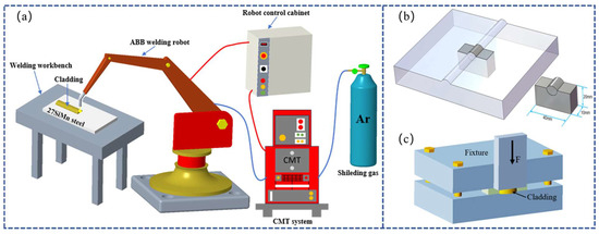
Figure 1.
(a) Schematic diagram of CMT cladding for Cu-Mn-Al alloy coatings. (b) Schematic illustration of the sample preparation. (c) Schematic diagram of the shear test setup.
Table 2.
Key parameters of the CMT cladding process.
After cladding, the coated plates were sectioned into metallographic specimens with dimensions of 40 mm × 20 mm × 10 mm using a wire electrical discharge machining (EDM) system, as illustrated in Figure 1b. The specimens were then sequentially ground with SiC sandpaper and polished using a polishing machine with 3 μm diamond polishing paste until a mirror-like finish was obtained.
To reveal the microstructure, different etchants were applied to the steel substrate and the Cu-Mn-Al cladding layer due to their distinct chemical compositions. The 27SiMn steel substrate was etched with a solution of 4% HNO3 + 4 mL HF + 92 mL H2O for approximately 10 s, while the Cu-Mn-Al cladding layer was etched with a solution of 1 g FeCl3 + 10 mL concentrated HCl + 20 mL ethanol for about 20 s. The etched samples were encapsulated with metallographic tape to protect the microstructure for subsequent observation and analysis.
2.3. Cladding Layer Performance Analysis
After grinding and polishing, the microstructure of the cladding layers was examined using a Helios 5CX Schottky field emission scanning electron microscope (SEM), coupled with energy-dispersive X-ray spectroscopy (EDS) to analyze the elemental distribution across the interface region. The phase composition of both the steel substrate and the Cu-Mn-Al cladding layer was characterized by a DX-2700BH X-ray diffractometer (XRD) with Cu Kα radiation.
For mechanical evaluation, the metallographic specimens (40 mm × 20 mm × 10 mm) were further sectioned into smaller test blocks of 10 mm × 5 mm × 5 mm using wire electrical discharge machining (EDM). A custom-designed shear fixture, schematically illustrated in Figure 1c, was employed to apply a shear force along the cladding–substrate interface at a constant crosshead speed of 0.5 mm/min. For each welding current condition (120, 150, 180, and 210 A), three replicate tests were conducted to ensure statistical reliability of the results. Figure 2 shows the fixtures used for the shear test and a photograph of the actual shearing process.
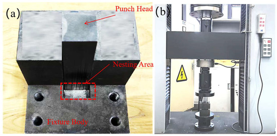
Figure 2.
(a) Fixtures. (b) Actual shearing process.
Electrochemical tests were conducted using a Corrtest CS310M electrochemical workstation in a conventional three-electrode configuration, where the cladding sample served as the working electrode, a saturated calomel electrode (SCE) was used as the reference, and a platinum sheet acted as the counter electrode. The exposed surface area of the working electrode was restricted to 0.5 cm2 with an O-ring. Prior to testing, the working electrode was polarized at −0.6 V for 5 min to stabilize the surface state. The open circuit potential (OCP) was recorded for 30 min, after which polarization and impedance measurements were performed. Linear polarization resistance (LPR) was determined by scanning from −0.6 V to 0.4 V at a rate of 1 mV/s, while electrochemical impedance spectroscopy (EIS) was carried out at OCP within a frequency range from 100 kHz to 10 mHz, using a sinusoidal perturbation amplitude of 3 mV.
3. Results and Discussion
3.1. Macroscopic Morphology Analysis
Through extensive preliminary experiments, it was observed that a too-slow CMT cladding speed led to severe oxidation on the cladding layer surface, while a too-fast speed caused welding defects such as undercut. A cladding speed of 0.54 m/min was identified as optimal for achieving sound surface formation. Therefore, this speed was fixed, and four welding current parameters (120 A, 150 A, 180 A, and 210 A) were selected for the cladding experiments. The surface morphology of the resultant clad beads is shown in Figure 3. Visually, a transition from a less continuous bead at 120 A to smoother and more uniform surfaces at higher currents (150–210 A) was observed, indicating improved process stability with increased heat input.
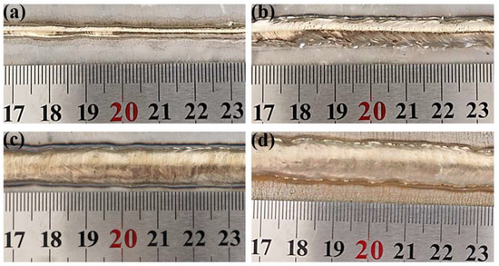
Figure 3.
Morphology of cladding layers under different welding currents. (a): 120 A; (b): 150 A; (c): 180 A; (d): 210 A.
To quantify these observations, the bead width and height were meticulously measured, as summarized in Figure 4. The cladding width exhibited a progressive increase from ~8.5 mm at 120 A to ~12.5 mm at 210 A. This direct correlation is attributed to the elevated heat input and correspondingly higher wire melting rate at larger currents, which creates a larger molten pool with greater fluidity, thereby enhancing lateral spreading. In contrast, the layer height remained relatively stable, fluctuating around a mean value of 3 mm without a consistent trend. This suggests that under a fixed travel speed, the vertical deposition rate is primarily governed by the wire feed speed (which is coupled to the current), while the gravitational force and fluidity ultimately limit the maximum achievable height, leading to a wider rather than taller bead.
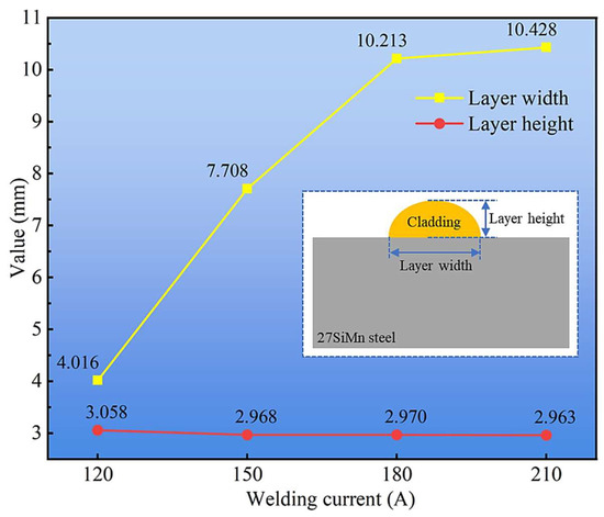
Figure 4.
Layer width and height of cladding layers under different welding currents.
The interfacial wetting behavior, a critical factor for bonding integrity, was assessed by measuring the wetting angle from polished cross-sections (Figure 5). The average wetting angle was largest (82.16°) at the lowest current of 120 A, suggesting a higher surface tension and restricted flow of the smaller molten pool. As the current increased to 150 A, the angle sharply decreased and then stabilized within a range of approximately 52° to 58° at 180 and 210 A. This significant improvement in wettability is a consequence of the increased heat input, which lowers the melt viscosity and enhances interfacial energy, promoting superior spreading and intimate contact with the steel substrate. A lower wetting angle is indicative of stronger metallurgical bonding and a reduced propensity for interfacial defects.
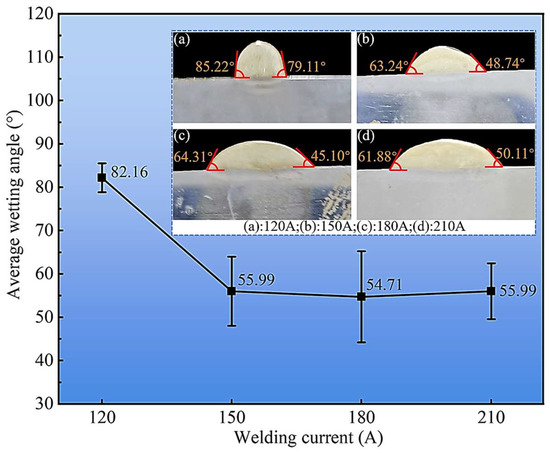
Figure 5.
Variation of cladding layer wetting angle with welding current. (a): 120 A; (b): 150 A; (c): 180 A; (d): 210 A.
In summary, this macroscopic analysis establishes that welding current is a decisive parameter controlling bead geometry and interfacial quality in CMT cladding. The increase in current directly promotes wider beads and significantly improved wettability, while the layer height remains largely constant under the given process window. These fundamental morphological characteristics set the foundation for understanding the subsequent microstructural evolution and mechanical performance reported in the following sections.
3.2. Microstructure Analysis
During the CMT cladding process, a Cu-Mn-Al alloy layer was deposited onto the surface of 27SiMn steel, forming a well-defined metallurgical bonding interface between the cladding layer and the steel substrate. To systematically characterize the microstructure across this interface, phase composition and morphology were investigated using X-ray diffraction (XRD), optical microscopy, and scanning electron microscopy (SEM), combined with energy-dispersive X-ray spectroscopy (EDS).
XRD patterns of the cladding layer surface and the base metal outside the cladding zone are shown in Figure 6. The base metal consisted primarily of α-Fe, whereas the cladding layer contained α-Cu, β-Cu3Al, Fe3Al, and κ phases. Slight leftward shifts in diffraction peaks were observed for both the base metal and cladding layer (e.g., 2θ(110) = 44.6° vs. 44.7° for α-Fe; 2θ(111) = 42.61° vs. 43.30° for Cu phases), which were attributed to residual stresses generated during the steel manufacturing process [33] and rapid cooling after cladding, respectively.
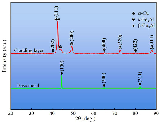
Figure 6.
XRD patterns of base metal and cladding layer.
Figure 7 presents the metallographic micrographs of the mid-section of the cladding layer under different welding currents. At 120 A and 150 A, the cladding layer consisted of α-Cu with a network-like morphology, lamellar α-Cu + κIII phases, blocky β-Cu3Al, and fine granular κII precipitates. At higher welding currents (180 A and 210 A), the α-Cu + κIII phase disappeared, petal-shaped κI phases emerged, and the volume fraction of α-Cu significantly increased. These changes are attributed to higher heat input at increased welding currents, which enhanced Fe diffusion from the steel substrate into the molten pool, facilitating the formation of κI phases during cooling. In contrast, lower heat input at 120 A and 150 A suppressed κI precipitation.
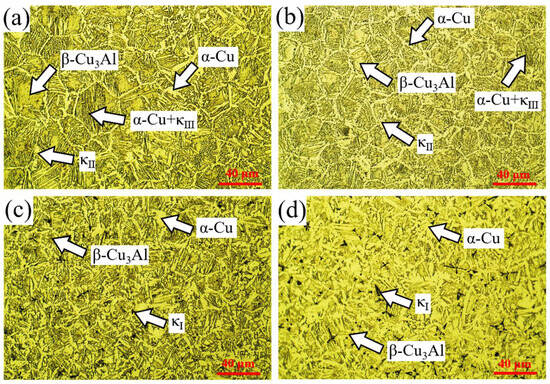
Figure 7.
Metallographic micrographs of the mid-section of cladding layers under different welding currents: (a) 120 A; (b) 150 A; (c) 180 A; (d) 210 A.
The microstructure of the base metal beneath the cladding layer was examined along the depth using an Olympus GX53 optical microscope, as shown in Figure 8. Four distinct regions were identified based on phase composition and morphology: Region A (complete quenching zone, adjacent to the substrate surface) exhibiting lath martensite (LM); Region B (incomplete quenching zone) containing a mixture of martensite (M), ferrite (F), and pearlite (P); Region C (normalizing zone) consisting of fine granular pearlite (GP) and granular ferrite (GF); and Region D (base metal zone) composed of coarse block pearlite (BP) and ferrite (BF). Regions A, B, and C together constitute the heat-affected zone (HAZ) of the substrate.
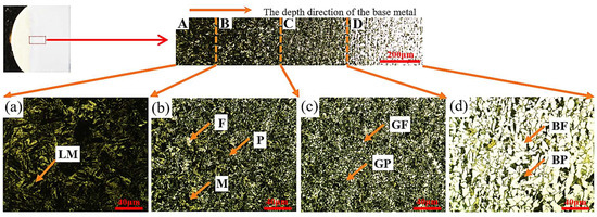
Figure 8.
Microstructural micrographs of the base metal along the depth direction.
The morphology of the cladding-substrate interface was further examined using SEM, and the interface width was quantified under different welding currents (Figure 9). The interface width increased with welding current up to 180 A, reaching a maximum of 2.332 μm, and then decreased at 210 A. This trend is closely related to the heat input: moderate heat input promoted adequate mixing and metallurgical bonding, whereas excessive heat input induced grain coarsening and reduced interface compactness.
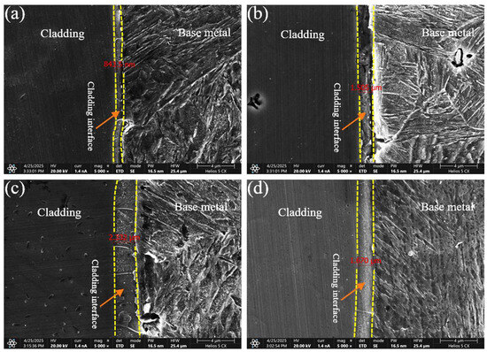
Figure 9.
Bonding interfaces between cladding layers and base metal under different welding currents: (a) 120 A; (b) 150 A; (c) 180 A; (d) 210 A.
To evaluate the chemical element distribution across the interface, EDS mapping was performed in representative regions near the cladding-substrate interface (Figure 10). The results revealed bidirectional elemental diffusion: a small amount of Fe diffused from the substrate into the copper-based cladding layer, leading to local enrichment of Fe at the interface, while Cu diffused from the cladding layer into the steel substrate, forming a gradual transition zone enriched with Cu within the HAZ. This elemental interdiffusion confirms strong metallurgical bonding, which is beneficial for the mechanical integrity of the cladding layer.
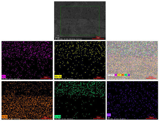
Figure 10.
EDS elemental mapping of a typical cladding interface region.
3.3. Mechanical Properties and Corrosion Resistance Analysis
Figure 11 presents the shear strength of cladding layers under different welding currents. The results reveal a non-monotonic trend with increasing current. The maximum average shear strength of 509.49 ± 15.2 MPa was obtained at 120 A, indicating the most effective metallurgical bonding and cohesive strength within the cladding. In contrast, the strength decreased markedly at higher current, reaching a minimum of 420.49 ± 22.1 MPa at 210 A, which suggests that excessive heat input deteriorated the interface integrity.
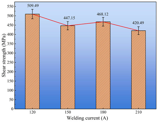
Figure 11.
Shear strength of cladding layers under different welding currents.
To analyze the shear fracture mechanism, the morphology of the shear fracture surface was examined by scanning electron microscope, as shown in Figure 12. Figure 12a shows that when the welding current was 120 A, a large number of shear dimples existed on the fracture surface, and the fracture belonged to micro-hole aggregation type ductile fracture. When the welding current was 150 A, a strip-shaped dimple area existed on the shear fracture surface (Figure 12b), and strip-shaped cleavage steps existed on both sides, indicating that both ductile fracture and cleavage fracture existed in the fracture process. The mixed ductile-brittle fracture mode may be because intermetallic compounds existed in the cladding layer, and brittle fracture occurred inside these compounds [34]. When the welding current was 180 A, a large number of dimples also existed on the fracture surface (Figure 12c), but their number and density were significantly lower than at 120 A, and the fracture mode belonged to ductile fracture. When the welding current was 210 A, bundle-shaped parallel cleavage steps were observed on the fracture surface (Figure 12d), with a small number of dimples. These results demonstrate a progressive transition in fracture behavior with increasing welding current: from predominantly ductile fracture at 120 A to mixed ductile–brittle behavior at 150 A, and finally to a quasi-brittle fracture mode at 210 A. The fracture surface at 210 A is characterized by parallel, bundle-like cleavage facets with only sparse dimples, features that are typical of quasi-cleavage fracture. Such morphology indicates a marked reduction in plasticity, which can be attributed to an increased volume fraction and coarsening of brittle intermetallic phases (e.g., κ and β phases) and to a less favorable interfacial condition at high heat input. The observed decrease in dimple density and the emergence of cleavage features therefore correlate with the XRD/SEM/EDS findings (Section 3.2) showing greater κ-phase formation, coarser α-Cu regions, and modified interface characteristics at higher currents—all of which facilitate crack initiation and propagation along brittle phases or weakened interface paths.
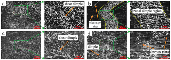
Figure 12.
SEM micrographs of shear fracture surfaces of cladding layers under different welding currents: (a) 120 A; (b) 150 A; (c) 180 A; (d) 210 A.
Figure 13 shows the microhardness distribution from the cladding surface to the base metal. The profile exhibits a non-monotonic trend, first increasing near the fusion line and then gradually decreasing toward the substrate. This behavior is attributed to the heterogeneous microstructural zones formed during CMT cladding: lath martensite (LM) in the quenched region exhibits the highest hardness, while the mixed M + F + P zone and the refined GP + GF zone retain relatively high values compared with the coarser BP + BF structure of the base metal. Consequently, hardness gradually stabilizes at the lower level characteristic of the substrate.
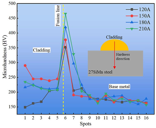
Figure 13.
Hardness variation from the top of cladding layer to base metal.
The effect of welding current on the average hardness of the cladding layers is summarized in Figure 14. Among all conditions, the 150 A sample exhibited the highest average hardness of 252.9 HV, which correlates with its finer α-Cu dendrites and higher dispersion of κ-phase precipitates observed in Section 3.2. In contrast, excessive heat input at 210 A promoted grain coarsening and phase segregation, leading to a measurable reduction in hardness. These results demonstrate that the hardness evolution is strongly governed by both the microstructural zoning across the cladding–substrate interface and the welding current–induced variations in phase constitution within the cladding layer.
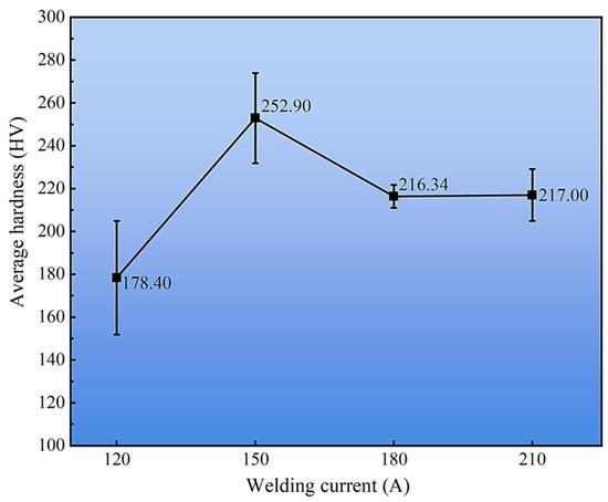
Figure 14.
Average hardness of cladding layers under different welding currents.
The corrosion resistance of the cladding layers was further evaluated by electrochemical tests, including potentiodynamic polarization and electrochemical impedance spectroscopy (EIS). Figure 15 presents the polarization curves under different welding currents, and the corresponding fitting parameters are listed in Table 3. Compared with the substrate, all cladding layers exhibited more positive corrosion potentials (Ecorr) and lower corrosion current densities (Icorr), confirming that the CMT-deposited coatings provide effective corrosion protection. Among them, the 120 A cladding displayed the lowest Icorr (0.046 mA·cm−2) and corrosion rate (0.411 mm·y−1), indicating the best overall corrosion resistance. Although the 180 A coating had the most positive Ecorr (−0.312 V), its corrosion current density was higher than that at 120 A, leading to only moderate corrosion resistance. At higher currents (150 A and 210 A), increased Icorr values and corrosion rates (>1.0 mm·y−1) reflected the detrimental effect of coarse phases and microstructural inhomogeneity. These observations suggest that corrosion performance cannot be judged from Ecorr alone but must be assessed by combining both thermodynamic (Ecorr) and kinetic (Icorr, corrosion rate) indicators [35].
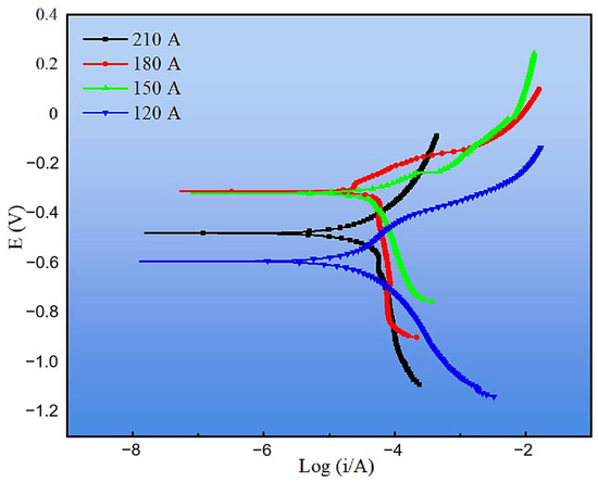
Figure 15.
Tafel curves of cladding layers under different welding currents.
Table 3.
Fitting results of Tafel curves for cladding layers and base metal under different welding currents.
To gain deeper insight into interfacial charge transfer behavior, EIS measurements were carried out, and the Nyquist plots are shown in Figure 16. The fitted charge transfer resistance (Rct) values of the cladding layers under 120, 150, 180, and 210 A were 1615.7, 701.5, 912.1, and 894 Ω·cm2, respectively. A higher Rct corresponds to slower electron transfer and thus improved corrosion resistance. Consistent with the polarization results, the 120 A cladding exhibited the largest Rct, confirming its superior resistance to electrochemical reactions. In contrast, the 150 A coating had the lowest Rct, reflecting its poor corrosion resistance due to the presence of coarse and segregated phases. The 180 A and 210 A coatings showed intermediate Rct values, in agreement with their moderate polarization behavior.
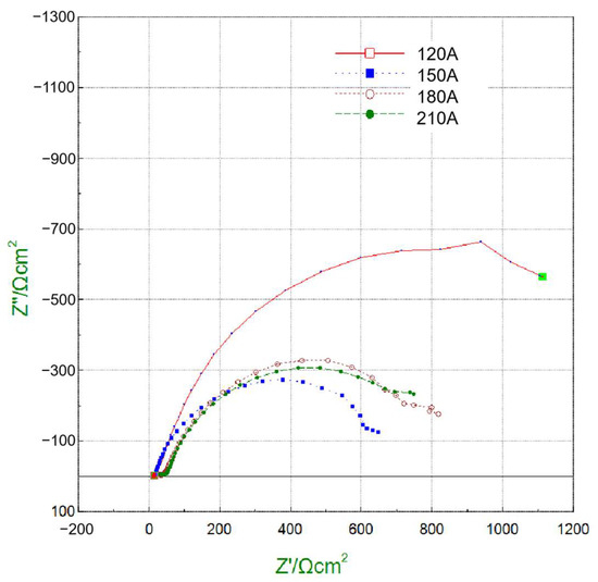
Figure 16.
Nyquist plots from EIS measurements for cladding layers under different welding currents.
Overall, the combined polarization and EIS results demonstrate that the cladding layer produced at 120 A provides the most effective corrosion protection. This improvement can be attributed to its refined and homogeneous microstructure, which suppresses the formation of continuous intermetallic networks and limits preferential dissolution sites. The compact morphology minimizes micro-defects such as pores or cracks, thereby reducing electrolyte penetration pathways. Moreover, the bidirectional diffusion of Cu and Fe across the interface forms a gradual transition zone, which not only enhances metallurgical bonding but also reduces galvanic potential differences between the coating and the substrate. In contrast, higher welding currents (150 and 210 A) promoted the precipitation of coarse κ phases and segregation of alloying elements, which act as local cathodic or anodic sites and accelerate micro-galvanic corrosion. The 180 A cladding, although exhibiting the most noble Ecorr, still contained microstructural heterogeneities that limited its long-term corrosion resistance. These findings highlight that the superior electrochemical stability of the 120 A cladding results from the synergistic effects of grain refinement, phase uniformity, and reduced micro-galvanic activity at the interface.
4. Conclusions
This study uses CMT technology to prepare Cu-Mn-Al alloy coatings on the surface of 27SiMn steel and analyzes the macro morphology, microstructure, mechanical properties and corrosion resistance of the cladding layers prepared under different welding currents. The research conclusions are as follows:
(1) Macroscopic morphology analysis shows that: with the increase of welding current, the layer width of the cladding layer gradually increases; the layer height fluctuates around 3 mm, and the welding current has no obvious effect on the layer height; when the welding current is 120 A, the average wetting angle of the cladding layer is the largest, reaching 82.16°; and when the welding current increases to 150 A, 180 A and 210 A, the average wetting angle decreases and stabilizes at about 55°.
(2) Microstructural analysis reveals that: when the welding current is 120 A and 150 A, the main phases in the cladding layer are α-Cu phase, κII phase, β-Cu3Al, and α-Cu + κIII phase; when the welding current is 180 A and 210 A, the α-Cu + κIII phase disappears in the cladding layer, and petal-shaped κI phase appears.
(3) The phases of the base metal are divided into four zones: quenching zone, incomplete quenching zone, normalizing zone, and base metal zone. The corresponding phases of the four zones are lath martensite (LM), martensite (M) + ferrite (F) + pearlite (P), granular ferrite (GF) + granular pearlite (GP), and block ferrite (BF) + block pearlite (BP), respectively.
(4) Analysis of mechanical properties and corrosion resistance shows that: when the welding current is 120 A, the shear strength reaches the maximum value of 509.49 MPa; when the welding current is 120 A and 180 A, the shear fracture mode of the cladding layer is ductile fracture, and when the welding current is 150 A and 210 A, the shear fracture mode of the cladding layer is ductile-brittle mixed fracture. When the welding current is 150 A, the average hardness of the cladding layer reaches the maximum value of 252.90 HV.
(5) Corrosion resistance analysis indicates that the cladding layer obtained at a welding current of 120 A exhibits the best corrosion resistance.
Author Contributions
Conceptualization, J.P.; methodology, J.P.; validation, J.P., S.X. and J.X.; formal analysis, S.X. and J.X.; investigation, J.P., S.X. and J.X.; resources, J.P., P.W. and N.C.; data curation, J.P., S.X. and J.X.; writing—original draft preparation, S.X. and J.X.; writing—review and editing, J.P., X.W. and Z.N.; visualization, S.X. and J.X.; supervision, J.P.; project administration, J.P.; funding acquisition, J.P. All authors have read and agreed to the published version of the manuscript.
Funding
This work was supported by the Key Scientific Research Projects of Higher Education Institutions in Henan Province (No. 24A460017), the Key R & D and Promotion Project of the Henan Province (Science and Technology Research) (No. 252102220064), and the Key R & D and Promotion Project of the Henan Province (Science and Technology Research) (No. 252102220078). The authors thank for the special funding and equipment support of the visiting professor at the School of Materials Science and Engineering.
Data Availability Statement
The original contributions presented in this study are included in the article. Further inquiries can be directed to the corresponding author(s).
Conflicts of Interest
The authors declare no conflicts of interest.
References
- Li, Z.; Chai, L.; Tang, Y.; Zhang, C.; Qi, L.; Zhang, K.; Peng, C.; Huang, C. 316L Stainless Steel Repaired Layers by Weld Surfacing and Laser Cladding on a 27SiMn Steel: A Comparative Study of Microstructures, Corrosion, Hardness and Wear Performances. J. Mater. Res. Technol. 2023, 23, 2043–2053. [Google Scholar] [CrossRef]
- Lu, X.; Zhang, Z.; Lv, M.; Li, X.; Song, B.; Fang, M. Evolution of Non-Metallic Inclusions in 27SiMn Steel. Metals 2022, 12, 718. [Google Scholar] [CrossRef]
- Wang, B.; Yang, W.; Liu, Y.; Zhang, T. Industrial Experiment of the Online Accelerated Cooling for 27SiMn Seamless Steel Pipe. Steel Res. Int. 2025, 96, 123–128. [Google Scholar] [CrossRef]
- Wu, Y.; Shuai, M.; Hou, X.; Wang, J.; Li, H.; Yan, J.; Zhao, G.; Jiao, H. Study on Dynamic Solidification Characteristics and Microstructure of Laser Cladded Coatings on the Surface of 27SiMn Alloy Structural Steel. Mater. Today Commun. 2025, 45, 112309. [Google Scholar] [CrossRef]
- Ito, T.; Tomita, K.; Taniguchi, K.; Igi, S.; Yamamoto, M. Elucidation of Dissimilar Material Joining Phenomena on Steel and Aluminum Alloy Using Hot-Wire Laser Brazing. Weld. World 2024, 68, 1375–1387. [Google Scholar] [CrossRef]
- Kraft, S.; Peters, O.; Schille, J.; Mušálek, R.; Martan, J.; Dlouhá, Ž.; Klečka, J.; Matějíček, J.; Houdková, Š.; Moskal, D.; et al. High-Speed Laser Surface Structuring for Thermal Spray Coating Preparation. Phys. Status Solidi A 2024, 221, 2300710. [Google Scholar] [CrossRef]
- Qiu, Y.; Wang, Y.; Shu, L.; Huang, T.; Shi, J.; Li, P. Microstructure and Properties of Ni-ZrB2; Gradient Composite Coating on the 27SiMn Steel Surface by Laser Cladding. Mater. Today Commun. 2025, 43, 111657. [Google Scholar] [CrossRef]
- Zahiri, R.; Sundaramoorthy, R.; Lysz, P.; Subramanian, C. Hardfacing Using Ferro-Alloy Powder Mixtures by Submerged Arc Welding. Surf. Coat. Technol. 2014, 260, 220–229. [Google Scholar] [CrossRef]
- Li, C.; Quan, G.; Zhang, Q.; Wang, X.; Li, X.; Kou, S. A Novel Amorphous Alloy Coating for Elevating Corrosion Resistance of X70 Pipeline Steel. J. Therm. Spray Technol. 2024, 33, 1612–1629. [Google Scholar] [CrossRef]
- Ding, Y.; Bi, W.; Zhong, C.; Wu, T.; Gui, W. A Comparative Study on Microstructure and Properties of Ultra-High-Speed Laser Cladding and Traditional Laser Cladding of Inconel625 Coatings. Materials 2022, 15, 6400. [Google Scholar] [CrossRef]
- Rajeev, G.P.; Kamaraj, M.; Bakshi, S.R. Al-Si-Mn Alloy Coating on Aluminum Substrate Using Cold Metal Transfer (CMT) Welding Technique. JOM 2014, 66, 1061–1067. [Google Scholar] [CrossRef]
- Das, B.; Panda, B.N.; Sharma, F.; Dixit, U.S. Recent Developments in Cladding and Coating Using Cold Metal Transfer Technology. J. Mater. Eng. Perform. 2024, 33, 3130–3147. [Google Scholar] [CrossRef]
- Meena, R.P.; Yuvaraj, N.; Vipin. A Review on Wire Arc Additive Manufacturing Based on Cold Metal Transfer. Mater. Manuf. Process. 2024, 39, 1315–1341. [Google Scholar] [CrossRef]
- Ain, M.Q.U.; Naik, D.K.; Rajendran, D.K.; Sekar, S. Comprehensive Analysis of Experimental Studies in Cold Metal Transfer Welding. Discov. Appl. Sci. 2025, 7, 590. [Google Scholar] [CrossRef]
- Selvi, S.; Vishvaksenan, A.; Rajasekar, E. Cold Metal Transfer (CMT) Technology—An Overview. Def. Technol. 2018, 14, 28–44. [Google Scholar] [CrossRef]
- Bellamkonda, P.N.; Dwivedy, M.; Addanki, R. Cold Metal Transfer Technology—A Review of Recent Research Developments. Results Eng. 2024, 23, 102423. [Google Scholar] [CrossRef]
- Tapiola, J.; Tuominen, J.; Vihinen, J.; Vuoristo, P. Sliding Wear Behavior of Cold Metal Transfer Cladded Stellite 12 Hardfacings on Martensitic Stainless Steel. Weld. World 2023, 67, 573–584. [Google Scholar] [CrossRef]
- Liu, S.; Li, Z.; Gao, J.; Wang, W. Enhancing Corrosion Resistance of AZ31B Magnesium Alloy Substrate in 3.5% NaCl Solution with Al-Si Coating Prepared by Cold Metal Transfer-Based Wire Arc Additive Manufacturing. Int. J. Electrochem. Sci. 2024, 19, 100763. [Google Scholar] [CrossRef]
- Li, G.; Xu, S.; Lu, X.; Zhu, X.; Song, J.; Guo, Y. Microstructural Evolution and Mechanical Properties of Ti Alloy/Stainless Steel Lap Joints during Cold Metal Transfer Technique with CuSi3 Filler Wire. J. Mater. Eng. Perform. 2020, 29, 5291–5306. [Google Scholar] [CrossRef]
- Liu, F.; Gao, X.; Zeng, Z.; You, Q.; Liu, F.; Wang, Z.; Xu, Y.; Zheng, H.; Liu, Q.; Lin, X.; et al. Comparative Study on Microstructure and Oxidation Resistance of Inconel 625 Superalloy Coatings on 12CrMoV Steel Surfaces Prepared by CMT and MIG Cladding. J. Mater. Res. Technol. 2024, 29, 3910–3922. [Google Scholar] [CrossRef]
- Li, X.Y.; Yan, Y.G.; Ma, L.; Xu, Z.M.; Li, J.G. Cavitation Erosion and Corrosion Behavior of Copper–Manganese–Aluminum Alloy Weldment. Mater. Sci. Eng. A 2004, 382, 82–89. [Google Scholar] [CrossRef]
- Rahni, M.R.M.; Beidokhti, B.; Haddad-Sabzevar, M. Effect of Filler Metal on Microstructure and Mechanical Properties of Manganese–Aluminum Bronze Repair Welds. Trans. Nonferrous Met. Soc. China 2017, 27, 507–513. [Google Scholar] [CrossRef]
- Zangene, D.; Kayvandarian, F.; Khodabakhshi, F.; Malekan, M.; Hájovská, Z. Nickel-Aluminum Bronze (NAB) Alloy Design under Two-Steps Casting and Submerged Friction Stir Processing. Mater. Sci. Eng. A 2024, 890, 145960. [Google Scholar] [CrossRef]
- Fröck, H.; Milkereit, B.; Broer, J.; Springer, A.; Wenner, S.; Oldenburg, K.; Kruse, T.; Kloetzer-Freese, C.; Kessler, O. Micro- and Nanostructural Evolution of Copper Bronze CuAl10Ni5Fe5 during Cooling from Solution Treatments. Mater. Charact. 2025, 221, 114795. [Google Scholar] [CrossRef]
- Dharmendra, C.; Hadadzadeh, A.; Amirkhiz, B.S.; Janaki Ram, G.D.; Mohammadi, M. Microstructural Evolution and Mechanical Behavior of Nickel Aluminum Bronze Cu-9Al-4Fe-4Ni-1Mn Fabricated through Wire-Arc Additive Manufacturing. Addit. Manuf. 2019, 30, 100872. [Google Scholar] [CrossRef]
- Qi, L.; Chai, L.; Li, Z.; Yang, T.; Zhou, J.; Cheng, R.; Zhang, K. Microstructure and Corrosion Resistance of an Al-Bronze Coating Prepared by Cold Metal Transfer on 27SiMn Steel. Surf. Coat. Technol. 2024, 478, 130493. [Google Scholar] [CrossRef]
- Yin, M.-Y.; Li, Z.; Xiao, Z.; Pang, Y.; Li, Y.-P.; Shen, Z.-Y. Corrosion Behavior of Cu−Al−Mn−Zn−Zr Shape Memory Alloy in NaCl Solution. Trans. Nonferrous Met. Soc. China 2021, 31, 1012–1022. [Google Scholar] [CrossRef]
- Li, Y.; Ngai, T.L.; Xia, W. Mechanical, Friction and Wear Behaviors of a Novel High-Strength Wear-Resisting Aluminum Bronze. Wear 1996, 197, 130–136. [Google Scholar] [CrossRef]
- Wang, B.; Wang, J.; Liu, X.; Li, Q.; Liu, X. Uncovering the Effects of Neutralizing Elements (Co, Mn and Cr) on the Fe-Rich Intermetallic Formation in Al-Si-Cu Alloys. Mater. Sci. Eng. A 2022, 858, 144090. [Google Scholar] [CrossRef]
- Meng, X.; Zhu, L.; Li, Y.; Hu, P.; Cai, G.; Liu, J.; Zhang, Q.; Dong, Z.; Zhang, X. The Influence of Ultrasonic Vibration on Micro-Arc Oxidation Behaviour of Manganese Aluminium Bronze. J. Mater. Res. Technol. 2024, 33, 758–772. [Google Scholar] [CrossRef]
- Guo, C.; Hu, B.; Wei, B.; Chen, F. Wire Arc Additive Manufactured CuMn13Al7 High-Manganese Aluminium Bronze. Chin. J. Mech. Eng. 2022, 35, 110. [Google Scholar] [CrossRef]
- Song, Q.N.; Zhang, H.N.; Li, H.L.; Hong, H.; Sun, S.Y.; Xu, N.; Zhang, G.Y.; Bao, Y.F.; Qiao, Y.X. Corrosion and Cavitation Erosion Behaviors of the Manganese-Aluminum-Bronze Cladding Layer Prepared by MIG in 3.5% NaCl Solution. Mater. Today Commun. 2022, 31, 103566. [Google Scholar] [CrossRef]
- Yi, X.; Ma, A.; Zheng, Y.; Li, Y.; Li, J.; Zhao, M.; Qiao, Y. Elucidating Different Selective Corrosion Behavior of Two Typical Marine Aluminum Bronze Alloys from the Perspective of Constituent Phases. Corros. Sci. 2024, 235, 112167. [Google Scholar] [CrossRef]
- Yang, L.M.; Zhang, Q.K.; Zhang, Z.F. Effects of Solder Dimension on the Interfacial Shear Strength and Fracture Behaviors of Cu/Sn–3Cu/Cu Joints. Scr. Mater. 2012, 67, 637–640. [Google Scholar] [CrossRef]
- Xu, C.; Peng, Y.; Chen, L.-Y.; Zhang, T.-Y.; He, S.; Wang, K.-H. Corrosion Behavior of Wire-Arc Additive Manufactured and as-Cast Ni-Al Bronze in 3.5 Wt% NaCl Solution. Corros. Sci. 2023, 215, 111048. [Google Scholar] [CrossRef]


Disclaimer/Publisher’s Note: The statements, opinions and data contained in all publications are solely those of the individual author(s) and contributor(s) and not of MDPI and/or the editor(s). MDPI and/or the editor(s) disclaim responsibility for any injury to people or property resulting from any ideas, methods, instructions or products referred to in the content. |
© 2025 by the authors. Licensee MDPI, Basel, Switzerland. This article is an open access article distributed under the terms and conditions of the Creative Commons Attribution (CC BY) license (https://creativecommons.org/licenses/by/4.0/).