Article

Microstructural Evolution and Tensile Properties of a Corrosion-Resistant Ni-Based Superalloys Used for Industrial Gas Turbines

1
State Key Laboratory of Long-Life High Temperature Materials, Deyang 618000, China
2
Dongfang Electric Corporation Dongfang Turbine Co., Ltd., Deyang 618000, China
3
Department of Materials Science and Engineering, Xi’an University of Technology, Xi’an 710048, China
*
Authors to whom correspondence should be addressed.
Crystals 2023, 13(4), 669; https://doi.org/10.3390/cryst13040669
Submission received: 29 March 2023 / Revised: 9 April 2023 / Accepted: 10 April 2023 / Published: 12 April 2023
(This article belongs to the Special Issue Experiments and Simulations of Superalloys)

Abstract

:
As an important mechanical property, tensile behavior has been regarded as an indicator for the creep and thermal mechanical fatigue properties of Ni-based superalloys. The tensile property of Ni-based superalloys is closely related to the amount, size, and distribution of γ -phase and carbides. To further clarify the tensile deformation mechanism of the CM247LC alloy, this study investigated its solidification characteristics and directionally-solidified and heat-treated microstructure. The dependence of tensile properties on the varied temperature ranging between 650 and 950 °C is discussed in detail. It was found that the deformation mechanism at 650 °C is dominated by the shearing of dislocations into the γ -precipitates to form the superlattice stacking faults. At 800 °C, the K-W lock leads to the anomalous yield effects. At 950 °C, the deformation mechanism is dominated by the dislocations bypassing the γ -precipiates. The results provide a comprehensive understanding of the CM247LC alloy and are beneficial for the development of corrosion-resistant Ni-based superalloys.

1. Introduction

CM247LC (low carbon) is derived from the conventional casting Mar-M 247 superalloy [1,2,3,4], which has been used in manufacturing the directionally solidified (DS) turbine blades for power generation applications. By reducing the contents of Zr and Ti combined with the control of Si and S in Mar-M247 alloy (Table 1), the grain boundary cracking during directional solidification was effectively suppressed [1]. Additionally, the carbide stability and intermediate temperature ductility were apparently improved for the CM247LC alloy [3]. According to the application condition of the DS turbine blades, the creep and thermal mechanical fatigue (TMF) properties of the CM247LC alloy have been extensively investigated in the past decades. However, it is worth noting that the tensile property is also an important mechanical property of Ni-based superalloys, which can be used as an indicator for the creep and TMF properties [5,6].
As is well known, the exceptional high-temperature mechanical properties of Ni-based superalloys mainly derive from the strengthening effect of L12-structured γ′-precipitates embedded in the γ-matrix and the pinning effect of carbides on the grain boundaries [7,8,9,10,11,12]. It has been proven that the size, volume fraction, morphology, and distribution of γ′-precipitates and carbide has a strong influence on the tensile properties of Ni-based superalloys [13,14,15]. For example, the extensive cracking of carbide was detected during a tensile test of the DS CM247LC alloy at a lower temperature [16]. Zhang et al. [17] pointed out that the anomalous yield strength with temperature was attributed to the shearing of dislocation into γ′-precipitates to form anti-phase boundary (APB). The microscopic deformation mechanism, derived from the interactions between the gliding dislocations and γ′-precipitates, depends on the temperature and heat-treated microstructural characteristics. Consequently, a comprehensive understanding of the tensile behavior and the internal deformation mechanism of the CM247LC alloy is still needed.
In this study, the CM247LC alloy was directionally solidified in the Bridgman furnace. The solidification characteristics, directionally-solidified and heat-treated microstructures, and the tensile properties at varied temperatures were investigated. The aim of this work was to reveal the microstructural characteristics of the CM247LC alloy and investigate the dependence of tensile performance on temperature. Additionally, the deformation mechanism with regard to the interaction between dislocation and γ′-precipitate was discussed in detail.

2. Experimental Procedures

The chemical compositions of the CM247LC and Mar-M247 alloys are listed in Table 1. The master alloy of CM247LC was prepared by the vacuum induction furnace, and then directionally solidified in a Bridgeman furnace described elsewhere [18]. The master alloy rod, 14 mm in diameter and 80 mm in length, was cast with a withdrawal rate of 3 mm/min and an approximate thermal gradient of 50 °C/cm. Then, the directionally-solidified samples were subjected to the following heat treatments: (1) 1232 °C/2 h +1257 °C/2 h, A.C. (air cooling) solution heat treatments; (2) 1080 °C/4 h, A.C. first aging treatment; (3) 870 °C/20 h, A.C., secondary aging treatment. The characteristic phase transformation temperature was measured by the differential scanning calorimetry (DSC, NETZSCH STA 449F3) with the heating/cooling rate of 10 °C/min in a flowing stream of Ar. Standard metallographic technique was applied for microstructural observation. The polished specimen was etched with a solution consisting of HNO3, HF, and C3H8O3 (1:2:3), and observed by optical microscopy (OM, OLYMPUS GX71/50), and scanning electron microscopy (SEM, TESCAN-MIRA3). In addition, the constituent phases were characterized using an X-Ray diffractometer (XRD, SHIMADZU XRD-7000) with the scanning rate of 3°/min.
The tensile specimens with the gauge section of 3 × 3 × 17 mm3 were cut from the directionally solidified specimen by electro-discharge machining (EDM), followed by heat treatment. Tensile tests were conducted on a SUNS CMT 5105 mechanical testing machine with the strain rate of 1 × 10⁻³ s−1 at 650, 800, and 950 °C. Three samples were selected for tensile testing to guarantee the reliability of testing results. To clarify the deformation mechanism, the interrupted tensile test was carried out with the approximate engineering plastic strain of 2~5%. The deformed specimen was observed by transmission electron microscopy (TEM, FEI TECNAI G2 F20). A thin TEM foil perpendicular to the tensile direction was prepared by twin-jet electropolishing in a solution of 10% (volume fraction) HClO4 and 95% C2H5OH at −40 °C.

3. Results and Discussion

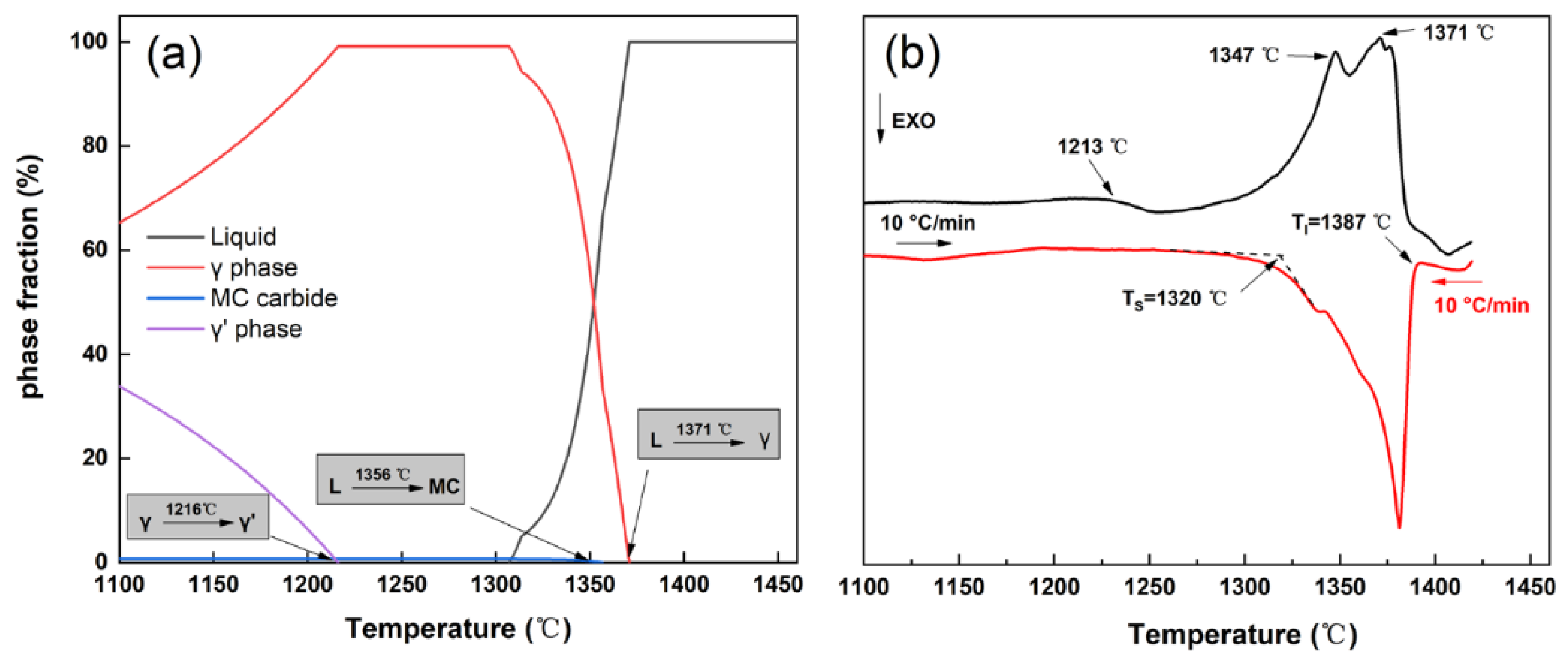
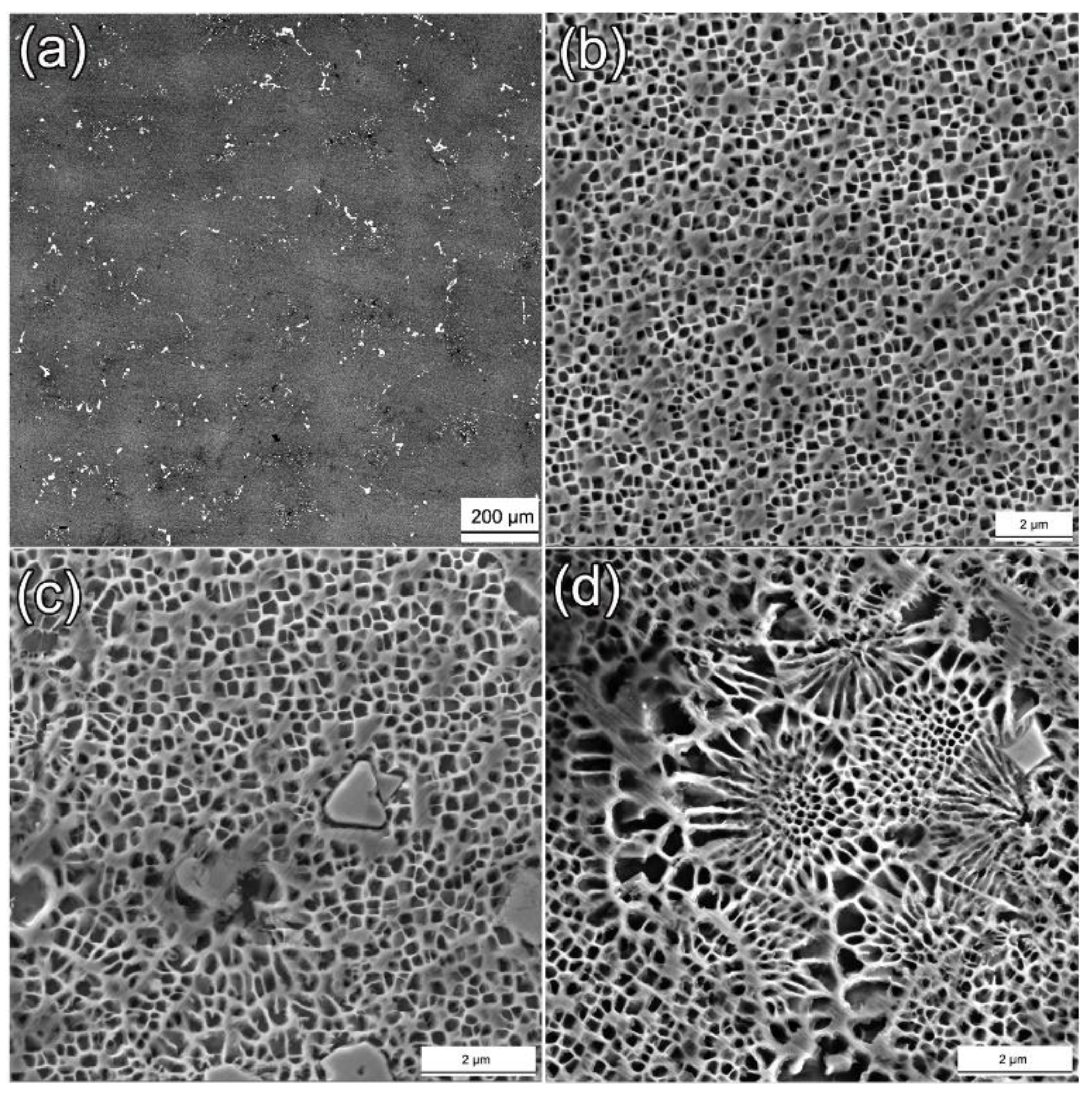
3.1. Solidification Characteristics and As-Cast Microstructure

The variation of the equilibrium volume fraction of the constituent phases with temperature was calculated by the software JMatPro (Figure 1a). The γ -phase firstly solidifies from the melt as the primary phase, followed with the MC carbide at 1356 °C. With the decreasing temperature, the strengthening γ -precipitate occurs at 1216 °C. Figure 1b shows the DSC heating and cooling curves of the as-cast specimen. Three endothermic peaks can be clearly observed on the DSC heating curve. The endothermic peaks at 1213, 1347, and 1371 °C on the DSC heating curve should be related to the solution temperature of the γ -precipitate, melting temperature of the MC carbide, and liquidus, respectively. The freezing range, defined as the temperature range between the solidus and liquidus on the DSC cooling curve, is approximately 67 °C, which has the good consistency with the thermodynamic calculation results.
Figure 2 exhibits the cross-sectional microstructure of the CM247LC alloy after directional solidification. The representative dendritic microstructure with the mean primary dendrite arm spacing of ~165 μm was obtained under the thermal gradient of ~50 °C/cm and withdrawal rate of 50 μm/s (Figure 2a). The dendritic core is composed of the L12-structured γ -particles with near-cubic shape embedded in the disordered-FCC γ -matrix (Figure 2b). Meanwhile, the blocky carbides have a strong tendency to distribute in the interdendritic region, and they are preliminarily judged as the MC carbides (Figure 2c). The coarse γ / γ eutectics also distribute in the interdendritic region with lamellar shape (Figure 2d). Moreover, the solute segregation in the as-cast microstructure was analyzed by the segregation ratio ( k ), as expressed by:
k = C D C / C I D
where C D C and C I D denote the chemical compositions of the dendritic core and interdendritic region, respectively. According to the definition of k , values of k greater or lesser than unity indicate the segregation tendency of constituent elements to the dendritic core or to the interdendritic region, respectively. As shown in Table 2, the γ -forming elements, Ti, Al, Ta, Hf, etc., partition to the interdendric region ( k < 1 ), while W and Co preferentially segregate to the dendrite core ( k > 1 ). Due to the segregation of the γ -forming elements during solidification, the size of γ -precipitates in the interdendritic region (Figure 2c,d) is apparently larger than that in the dendritic core (Figure 2b).
Figure 3 presents the TEM-EDS mapping and the selected electron diffraction (SAED) pattern of the carbide. The SAED patterns definitely indicates that the blocky particle is the MC carbide. Meanwhile, TEM-EDS mapping confirms that the MC carbide is enriched in Ta, Hf, Zr, and Ti, and depleted in Ni, Cr, and B. The solidification temperature of the MC carbide is about 15 °C lower than the liquidus. During directional solidification, Ta, Hf, Ti, etc., segregate to the remaining liquid in the mushy zone, thus promoting the formation of MC carbides. Due to the restriction of the primary dendric arms and the complicated thermosolutal convection in the mushy zone, the MC carbide exhibits an irregular morphology.

3.2. Heat-Treated Microstructure

Figure 4 shows the carbide and dendritic core of the CM247LC alloy after solution and two steps aging heat treatment. As shown in Figure 4a, the carbides still locate in the interdendritic region but with the more homogeneous distribution and refined size, compared with the counterpart in the as-cast specimen (Figure 2a). Table 3 shows the chemical composition of the carbide in directionally solidified and heat-treated specimens. According to the SEM-EDS results, the carbide enriched with Ta and Hf is identified as an MC carbide. Figure 4b–d exhibit the γ -precipitates in the dendritic core after solution and aging heat treatments. In this investigation, a step-wise solution heat treatment up to 1257 °C was applied to dissolve the coarse γ / γ eutectic and reduce the degree of dendritic segregation. As shown in Figure 4a, the small γ -particles (0.159 μm) with near-spherical morphology distribute in the dendritic core, which can be attributed to the high nucleation driving force of the supersaturated γ -matrix and the limited growth time during air cooling after solution treatment. Then, the two-steps aging treatments (1080 °C/4 h, A.C. + 870 °C/20 h, A.C.) are used to promote the reprecipitation of the γ -phase. As shown in Figure 4b–d, the γ -size significantly increased from 0.159 μm (solution heat treatment) to 0.295 μm (1st aging treatment), and finally to 0.312 μm (2nd aging treatments). After stepwise aging heat treatments, the γ -volume fraction increased from 40.6% (first aging treatment) to 50.8% (second aging treatments). Meanwhile, the morphology of the γ -precipitate changed from near-spherical to a cubic shape after aging heat treatments. The cubicity of the γ -precipitates depends on the competition between the interfacial energy and strain energy [18]. When the γ -size is small, the interface energy is the dominated factor to determine the near-spherical shape of γ -precipitates. With the increasing γ -size, the strain energy derived from the coherent misfit between γ and γ gradually plays a major role, resulting in the cubic morphology of the γ -phase.

3.3. Tensile Property and Deformation Mechanism

Figure 5 demonstrates the engineering strain–stress curves and the corresponding tensile properties of the CM247LC alloy at different temperatures. As shown in Figure 5a, the σ ε curves exhibit different characteristics with the increasing temperature. In the temperature range between RT and 650 °C, a significant strain-hardening phenomenon occurs after yield, and lasts to the final fracture. Particularly, the σ ε curve at 650 °C illustrates the strongest strain-hardening ability, while the flow stress at 800 and 950 °C rapidly rises to the ultimate tensile strength ( σ U T S ), and then gradually declines until fracture. Figure 5b shows the yield strength ( σ Y ), ultimate tensile strength and the fracture strain ( ε f ) at different temperatures. From RT to 500 °C, σ Y , σ U T S , and ε f decrease slightly. By contrast, σ Y and σ U T S respectively increase from 764 and 898 MPa at 500 °C to 1021 and 1126 MPa at 800 °C, and then drop to 538 and 693 MPa at 950 °C. An obvious anomalous yield behavior is observed for the CM247LC alloy. Generally, the different between σ Y and σ U T S , ( σ U T S σ Y ), can be used to characterize the strain-hardening ability. As shown in Figure 5a, σ ε curve demonstrates the highest value of ( σ U T S σ Y ) at 650 °C, indicating the strongest strain-hardening ability. In addition, the fracture strain decreases first from RT to 500 °C, and then increases continuously from 500 to 950 °C.
Figure 6 demonstrates the fracture surface and deformed microstructure after tensile tests at 650, 800, and 950 °C. At 650 °C, the fracture surface inclines about 45° with respect to the stress axis without apparent necking being observed (Figure 6(a1)). Plenty of cleavage steps and river patterns can be clearly seen on the enlarged SEM image of the fracture surface (Figure 6(a2)), indicating that the fracture models to a cleavage fracture. Furthermore, as shown in Figure 7, the crack of the MC carbide is observed near the fracture surface at the tensile temperature of 650 °C. The crack propagation is observed along the interface between carbide and matrix, indicating the detrimental effects of blocky MC carbide on the tensile properties of the CM247LC alloy at 650 °C.
At 800 °C, the inclined angle between the macroscopical fracture surface and tensile stress axis increases apparently (Figure 6(b1)). Both cleavage steps and dimples can be observed on the fracture surface, demonstrating the mixed facture characteristics at 800 °C (Figure 6(b2)). At 950 °C, the fracture surface is perpendicular to the stress axis with an apparent necking phenomenon near the surface (Figure 6(c1)). Coarse dimples and small oxide particles are observed on the fracture surface, indicating a larger deformation before the fracture at 950 °C (Figure 6(c2)). Figure 6(a3–c3) exhibit the deformed microstructure near the fracture surface. No evident change in the morphology of the γ -precipitates can be observed at 650 °C. However, the γ -precipitates were gradually distorted along the tensile direction at the higher temperatures from 800 to 950 °C, which is mainly attributed to the high stress and the increased thermal activation at high temperatures.
For Ni-based superalloys, the fracture mechanism is closely related to the microstructural characteristics and tensile temperatures. Particularly, the size, distribution, and morphology of carbides have a strong influence on the fracture behavior. As an obstacle for dislocation motion, the MC carbide initially provides strengthening effects during tensile deformation. However, the pile-up of dislocations near the large blocky carbide will result in a local stress concentration, thus leading to the initiation and quick propagation of micro-cracks near the interface between carbide and matrix. Therefore, a low fracture strain was observed when the temperature was below 650 °C (Figure 5a). By contrast, as the temperature increases to 950 °C, more slip systems can be activated. Furthermore, when the local stress concentration exceeds the critical value, the partial dislocations can bypass or shear the γ -precipitates (as shown in the following section) to release the local stress concentration. Therefore, the tensile specimens exhibit a higher fracture strain and plastic deformation with the increasing temperature.
Figure 8 shows the TEM images of the deformed microstructure after interrupted tensile tests with 2–5% plastic strain. At 650 °C, the dislocation tangles in the γ -matrix accompanied with isolated superlattice stacking faults (SSF) in the γ -precipitates are clearly observed (Figure 8a). The isolated SSFs distribute along the <110> orientations, which can be attributed to the cutting of partial dislocations from the γ -matrix into the γ -precipitates. When the temperature increases to 800 °C, the dislocation density increases significantly in γ -matrix channels (Figure 8b,c). The dislocations severely tangle in the γ -channels, accompanied with the increased density of SSFs in the γ -precipitates. It is worth noting that there are some local serrated dislocations along the <010> direction (as marked by the red arrow in Figure 8b), which is generally named the Kear–Wilsdorf (K-W) lock [12]. It has been proven that the cross-slip of dislocations from the {111} to the {100} planes leads to the formation of the K-W lock [12,19], thus resulting in the anomalous yield behavior at 800 °C. With the increasing tensile temperature of 950 °C, the SSFs observed in the interrupted tensile specimens at the lower temperature totally disappeared, while a high density of dislocations presents in the γ channels. According to the TEM observations (Figure 8d), It can be deduced that the tensile behavior of the CM247LC alloy at 950 °C is determined by the cross-slip of dislocations in the γ -matrix with thermal activation.
The γ -phase is the main strengthening phase for the CM247LC alloy. The interactions between γ -precipitates and gliding dislocations play a critical role in the deformation of the CM247LC alloy at varied temperatures. The Burgers vector of full dislocation in the L12-structured γ -phase ( < 110 > ) is twice in magnitude that in the disordered γ -matrix ( 1 2 < 1 1 0 > ), which is named as the super-dislocation. The < 110 > super-dislocation tends to dissociate into partial dislocations due to its prohibitively high energy. According to proceeding publications [12,20], the cutting of a partial dislocation into γ -precipitates will lead to planar defects, including anti-phase boundary (APB) and superlattice stacking faults (SSFs). For example, a 1 2 < 1 1 0 > partial dislocation cut into the γ -phase will lead to the formation of APB; a 1 6 < 112 > partial dislocation cut into the γ -precipitates will result in a complex stacking fault (CSF); a 1 3 < 112 > partial dislocation cut into the γ -precipitates will lead to a superlattice intrinsic stacking fault (SISF). Generally, the barrier for partial dislocation cutting into the γ -phase follows the order of CSF > APB > SISF [12]. In this work, the isolated SISFs were clearly observed in the deformed specimen at 650 °C, indicating the cutting of a 1 3 < 112 > partial dislocation into the γ -phase. One typical dislocation reaction model has been proposed as [20]:
1 2 [ 1 01 ] + 1 2 [ 0 1 1 ] 1 3 [ 1 1 2 ] + 1 6 [ 1 1 2 ]
The reaction of two 1 2 < 110 > full dislocations in the γ -matrix results in a dislocation pair consisting of a 1 3 < 112 > leading dislocation and a 1 6 < 112 > trailing dislocation. At 650 °C, the dislocation glides first in the soft γ -matrix channels. With the accumulated dislocation density at the γ / γ interface, the local stress concentration will activate a slip of partial dislocations from different slip systems, thus leading to the intersection of SSFs within the γ -precipitates. Consequently, the CM247LC alloy exhibits a high work hardening ability at 650 °C. This is according to the Considère criterion [21], as expressed by:
d σ T d ε T < σ T
where σ T denotes true stress and ε T true strain. The necking instability will occur when the strain-hardening rate drops to the value of the true stress. In other words, a higher strain-hardening ability renders a higher tensile ductility. Therefore, as shown in Figure 5, the highest strain-hardening capability at 650 °C leads to a high uniform strain until fracture.
At 800 °C, the CM247LC alloy exhibits the highest yield and tensile strength, which can be attributed to the following reason. On the one hand, a K-W lock is formed in the γ -precipitates at 800 °C, which is attributed to the cross-slip of dislocation with the help of thermal activations. The anomalous yield strengthening effect makes the cutting of partial dislocations into the γ -precipitates much harder. On the other hand, the lattice misfit between γ and the γ -phase, δ , is defined as:
δ = 2 × a γ a γ a γ + a γ
where a γ and a γ are the lattice parameters of the γ and γ -phases, respectively. It has been proven that the expansion coefficient of γ is considerably higher than that of the γ -phase [12,22]. Although the exact value of δ for the CM247LC alloy was not obtained by an experimental method in this work, the tendency δ versus temperature is similar for most Ni-based superalloys. For example, Harada et al. [23] demonstrated that the value of δ becomes more negative with the increasing temperature for single-crystal Ni-based superalloys, including TMS63, TMS12, and CMSX-4. The J-MatPro calculation result illustrates that a γ = 0.3615 nm and a γ = 0.3611 nm at 650 °C, which yields a positive δ of ~0.116% for the CM247LC alloy, while, a γ = 0.3638 nm and a γ = 0.3643 nm at 950 °C, which yields a more negative δ of −0.125%. δ becomes more negative with the increasing temperature, thus leading to a higher coherency strain as the obstacle for dislocations motion. Therefore, the cutting of partial dislocations from the γ -matrix channel into the γ -precipitate becomes more difficult. The accumulated dislocations near the γ / γ interface, SSFs, and K-W lock lead to the strain-hardening effects. However, at the same time, the local stress concentration near the γ / γ interface can be relieved by the cross-slip and climb of dislocations with the help of thermal activation, which is termed as the softening effect. The feature of stress–strain curves depends on the competition between strain-hardening and softening effects. Initially, the strain-hardening effect plays the dominant role, thus leading to the quickly increased flow stress up to the ultimate tensile strength. Then, the flow stress decreases with the increasing strain due to the softening effects caused by thermal activation.
At 950 °C, the gliding dislocations were mainly constricted to the soft γ -matrix channel during tensile deformation. The tensile deformation at 950 °C is dominated by the climb and cross-slip of dislocations under the significant thermal activations in the γ -matrix to bypass over the γ -precipiates. Therefore, the stress–strain curve illustrates an obvious softening phenomenon at 950 °C.

4. Conclusions

The CM247LC alloy was prepared with the directional solidification technique. The solidification characteristics, solution, heat-treated microstructure, and tensile properties of the CM247LC alloy are investigated. The following conclusions are listed as follows:
(1)
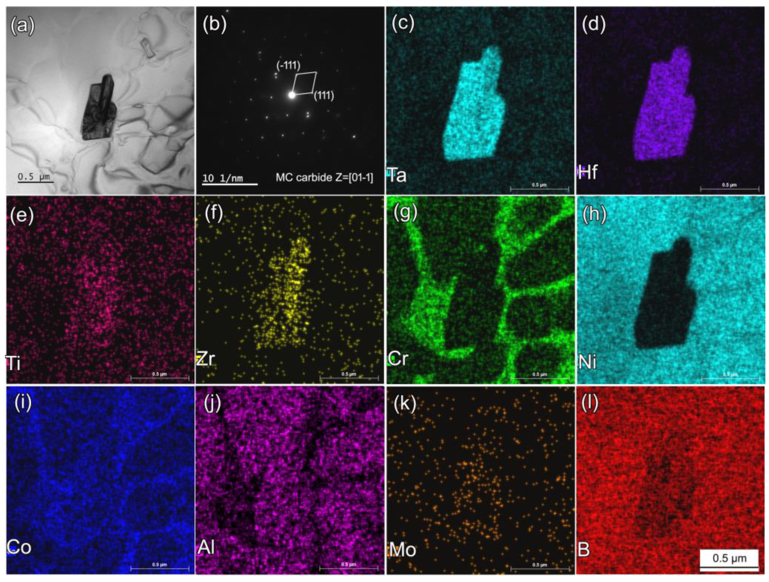
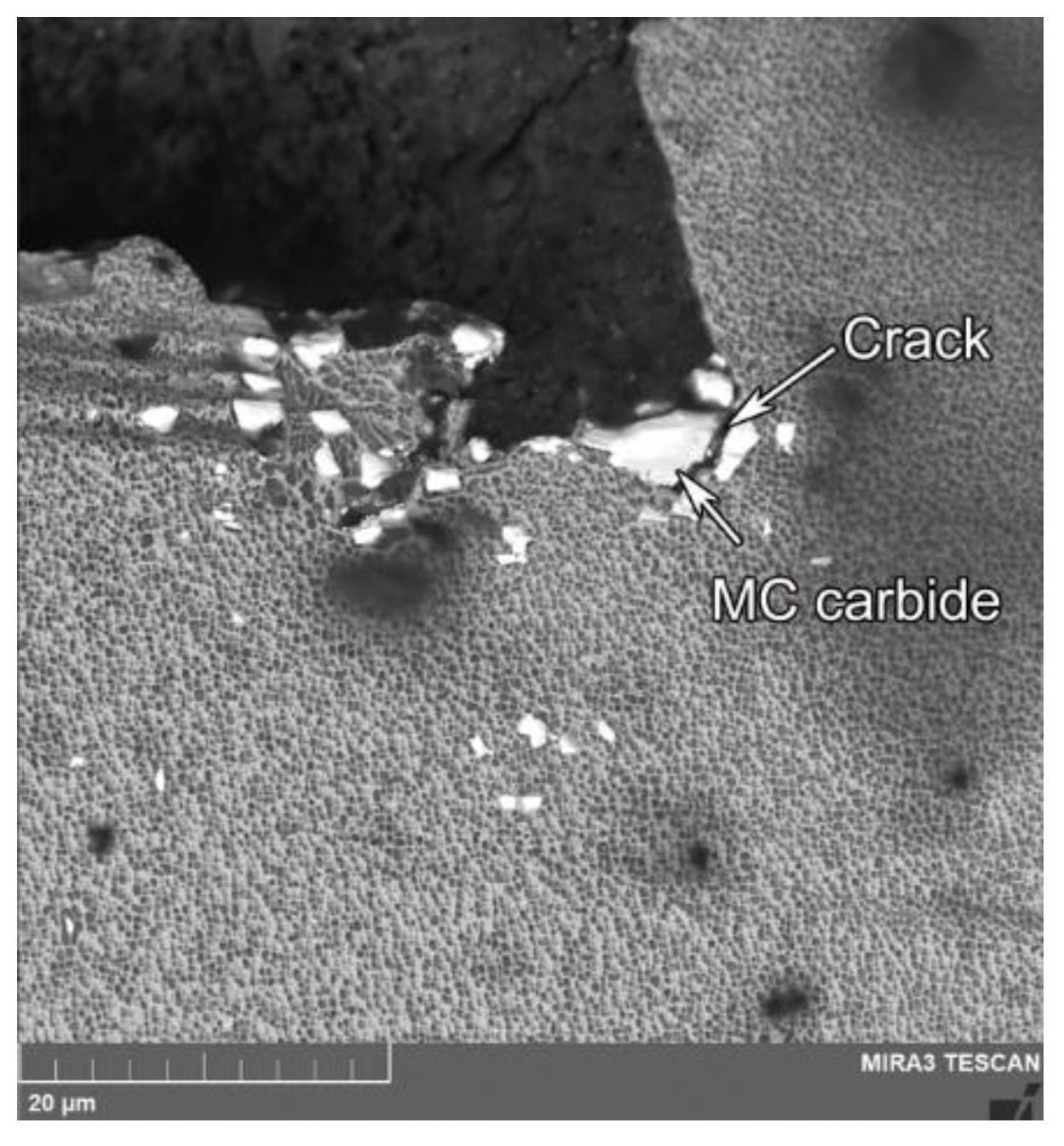
The directionally-solidified specimen exhibited a representative dendritic microstructure. The γ -phase first solidified from the melt as the primary phase, followed with the solidification of MC carbide at 1347 °C. MC carbides enriched with Ta, Hf, and Ti mainly distributed in the interdendritic region. Due to the solute segregation of Ta, Ti, Al, etc., a γ / γ eutectic with lamellar structure was found in the interdenritic region.
(2)
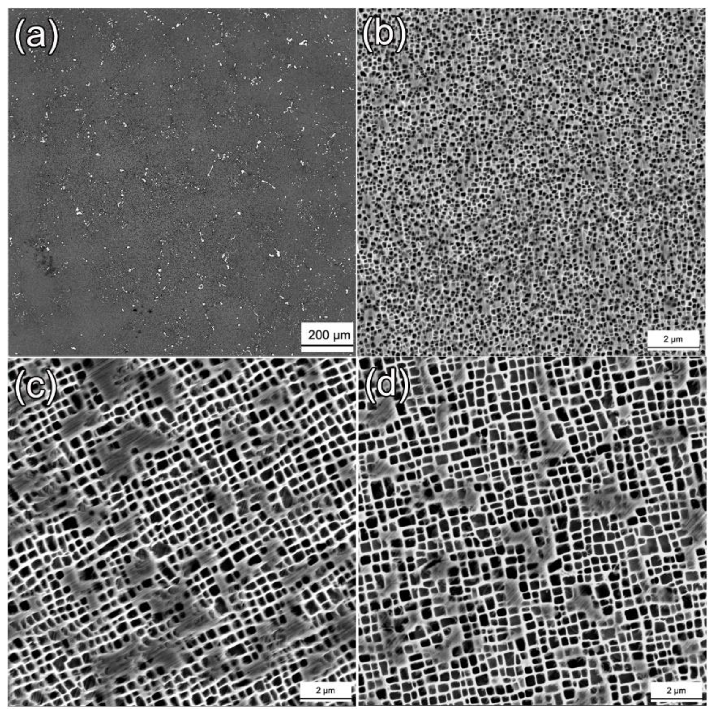
After 1232 °C/2 h +1257 °C/2 h, A.C solutioning and 1080 °C/4 h, A.C., +870 °C/20 h, A.C., aging treatments, a homogenous distribution of γ -precipitates embedded in the γ -matrix was obtained, along with the γ -size of 0.31 μm and γ -volume fraction of ~50.8%.
(3)
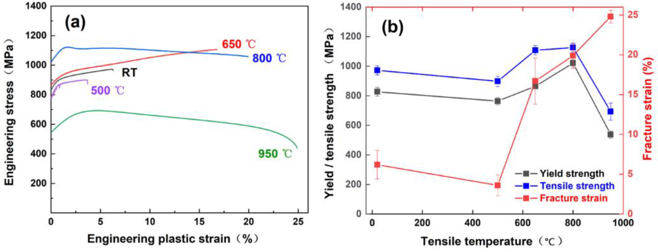
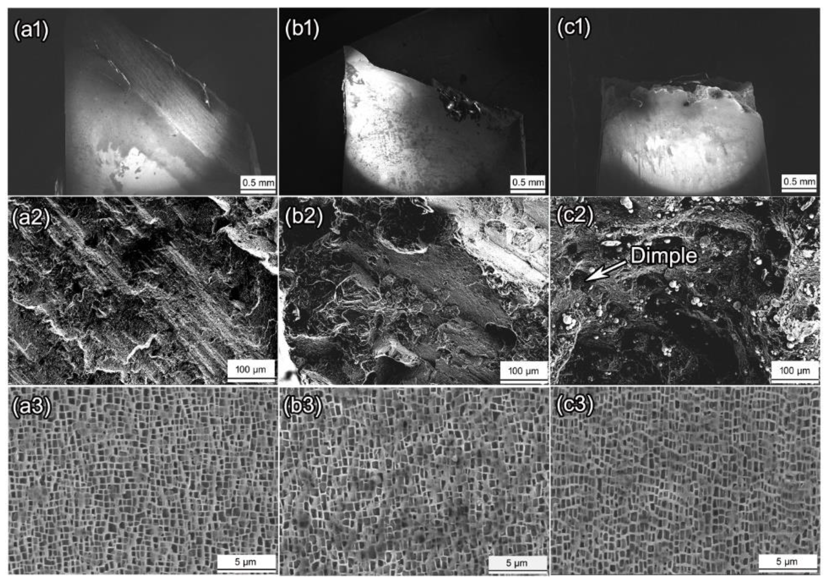
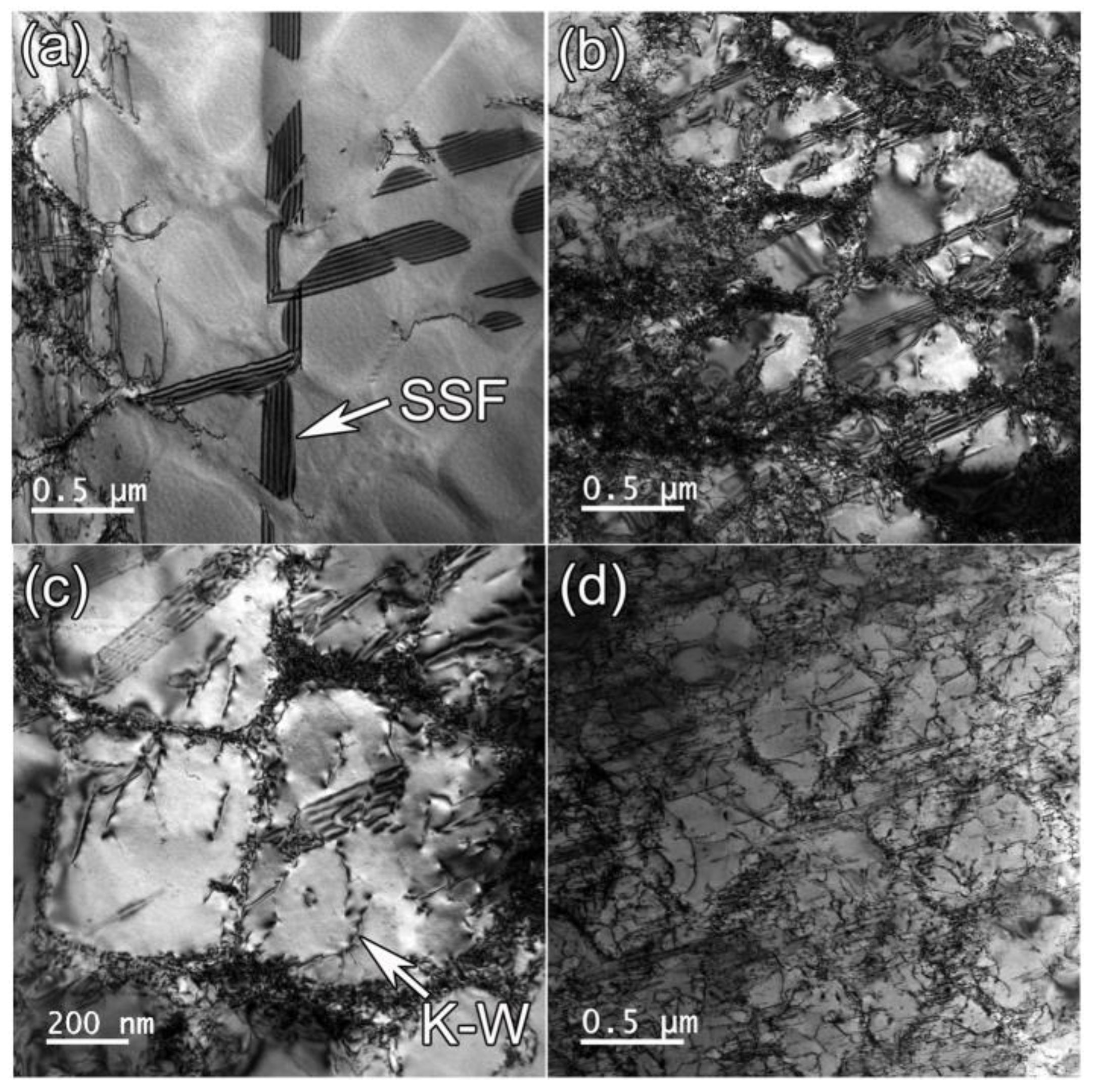
At 650 °C, the tensile deformation was dominated by the shearing of partial dislocation into γ -precipitates to form SSFs. At 800 °C, the K-W lock resulted in anomalous yield effects. The tensile specimen showed the highest σ Y of 1021 MPa and σ U T S of 1126 MPa at 800 °C. The tensile deformation was controlled by the dislocations bypassing the γ -precipiates at 950 °C.

Author Contributions

Conceptualization, Z.G. and G.L.; investigation, S.L. (Shikun Li), Z.S. and D.S.; writing—original draft preparation, Z.G. and G.L.; writing—review and editing, G.Y. and J.Z.; supervision, S.L. (Shuhua Liang); All authors have read and agreed to the published version of the manuscript.

Funding

This research was funded by the fund of State Key Laboratory of Long-life High Temperature Materials (DEC8300CG202111716EE280355).

Data Availability Statement

Data is contained within the article.

Conflicts of Interest

The authors declare no conflict of interest.

References

  1. Harris, K.; Erickson, G.L.; Schwer, R.E. Mar M 247 Derivations-CM 247 LC DS alloy and CMSX single crystal alloys: Properties and performance. In Superalloys 1984, Proceedings of the 5th International Symposium on Superalloys, Champion, PA, USA, 7–11 October 1984; TMS: Warrendale, PA, USA, 1984; pp. 221–230. [Google Scholar]
  2. Huang, H.E.; Koo, C.H. Characteristics and mechanical properties of polycrystalline CM 247 LC superalloy casting. Mater. Trans. 2004, 45, 562–568. [Google Scholar] [CrossRef] [Green Version]
  3. Rai, R.K.; Sahu, J.K. Strength-ductility paradox in a directionally solidified nickel base superalloy. Mater. Lett. 2018, 220, 90–93. [Google Scholar] [CrossRef]
  4. Jeong, H.W.; Seo, S.M.; Choi, B.G.; Yoo, Y.S.; Ahn, Y.K.; Lee, J.H. Effect of long-term thermal exposures on microstructures and mechanical properties of directionally solidified CM247LC alloy. Met. Mater. Int. 2013, 19, 917–925. [Google Scholar] [CrossRef]
  5. Zhou, H.; Harada, H.; Ro, Y.; Okada, I. Investigations on the thermo-mechanical fatigue of two Ni-based single-crystal superalloys. Mater. Sci. Eng. A 2005, 394, 161–167. [Google Scholar] [CrossRef]
  6. Ye, W.M.; Hu, X.T.; Song, Y.D. The relationship between creep and tensile properties of a nickel-based superalloy. Mater. Sci. Eng. A 2020, 774, 138847. [Google Scholar] [CrossRef]
  7. Alizadeh-Sh, M.; Marashi, S.P.H.; Ranjbarnodeh, E.; Shoja-Razavi, R.; Oliveira, J.P. Prediction of solidification cracking by an empirical-statistical analysis for laser cladding of Inconel 718 powder on a non-weldable substrate. Opt. Laser Technol. 2020, 128, 106244. [Google Scholar] [CrossRef]
  8. Li, S.; Li, J.Y.; Jiang, Z.W.; Cheng, Y.; Li, Y.Z.; Tang, S.; Leng, J.Z.; Chen, H.X.; Zou, Y.; Zhao, Y.H.; et al. Controlling the columnar-to-equiaxed transition during directed energy deposition of Inconel 625. Addit. Manuf. 2022, 57, 102958. [Google Scholar] [CrossRef]
  9. Rodrigues, T.A.; Farias, F.W.C.; Zhang, K.P.; Shamsolhodaei, A.; Shen, J.J.; Zhou, N.; Schell, N.; Capek, J.; Polatidis, E.; Santos, T.G.; et al. Wire and arc additive manufacturing of 316L stainless steel/Inconel 625 functionally graded material: Development and characterization. J. Mater. Res. Technol. 2022, 21, 237–251. [Google Scholar] [CrossRef]
  10. Liu, D.Y.; Ding, Q.Q.; Zhou, Q.; Zhou, D.X.; Wei, X.; Zhao, X.B.; Zhang, Z.; Bei, H.B. Microstructure, mechanical properties and thermal stability of Ni-based single crystal superalloys with low specific weight. Crystals 2023, 13, 610. [Google Scholar] [CrossRef]
  11. Harrison, J.; Withey, P.A. Precipitation of topologically closed packed phases during the heat-treatment of Rhenium containing single crystal Ni-based superalloys. Crystals 2023, 13, 519. [Google Scholar] [CrossRef]
  12. Reed, R.C. The Superalloys: Fundamentals and Applications; Cambridge University Press: Cambridge, UK, 2006. [Google Scholar]
  13. Kim, I.S.; Choi, B.G.; Seo, S.M.; Kim, D.H.; Jo, C.Y. Influence of heat treatment on microstructure and tensile properties of conventionally cast and directionally solidified superalloy CM247LC. Mater. Lett. 2008, 62, 1110–1113. [Google Scholar] [CrossRef]
  14. Kim, I.S.; Choi, B.G.; Jung, J.E.; Do, J.; Seok, W.Y.; Lee, Y.H.; Jeong, I.Y. Effect of heat treatment on microstructural evolution and creep behaviors of a conventionally cast nickel-based superalloy. Mater. Character. 2020, 165, 110378. [Google Scholar] [CrossRef]
  15. Sheng, L.Y.; Yang, F.; Guo, J.T.; Xi, T.F. Anomalous yield and intermediate temperature brittleness behaviors of directionally solidified nickel-based superalloy. Trans. Nonferr. Met. Soc. China 2014, 24, 673–681. [Google Scholar] [CrossRef]
  16. Rai, R.K.; Sahu, J.K.; Jena, P.S.M.; Das, S.K.; Paulose, N.; Fernando, C.D. High temperature tensile deformation of a directionally solidified nickel base superalloy: Role of micro constituents. Mater. Sci. Eng. A 2017, 705, 189–195. [Google Scholar] [CrossRef]
  17. Zhang, P.; Yuan, Y.; Gao, Z.H.; Gu, Y.F.; Li, J.; Yan, J.B.; Gong, X.F.; Lu, J.T.; Shi, X.B.; Fu, B.Q. Strain-rate insensitive yield strength and deformation mechanisms of Ni-base superalloy CM247LC at 600 °C. J. Alloys Compd. 2021, 862, 158478. [Google Scholar] [CrossRef]
  18. Liu, G.; Liu, L.; Ai, C.; Ge, B.M.; Zhang, J.; Fu, H.Z. Influence of withdrawal rate on the microstructure of Ni-base single-crystal superalloys containing Re and Ru. J. Alloys Compd. 2011, 509, 5866–5872. [Google Scholar] [CrossRef]
  19. Rai, R.K.; Sahu, J.K.; Jena, P.S.M.; Das, S.K.; Paulose, N.; Fernando, D.C. Micromechanism of High-Temperature Tensile Deformation Behavior of a Directionally Solidified Nickel Base Superalloy. J. Mater. Eng. Perform. 2018, 27, 659–665. [Google Scholar] [CrossRef]
  20. Long, H.; Liu, Y.; Kong, D.; Wei, H.; Chen, Y.; Mao, S. Shearing mechanisms of stacking fault and anti-phase-boundary forming dislocation pairs in the γ′ phase in Ni-based single crystal superalloy. J. Alloys Compd. 2017, 724, 287–295. [Google Scholar] [CrossRef]
  21. Dieter, G.E.; Bacon, D. Mechanical Metallurgy; McGraw-Hill: New York, NY, USA, 1986. [Google Scholar]
  22. Wang, G.L.; Liu, J.L.; Liu, J.D.; Wang, X.G.; Zhou, Y.Z.; Sun, X.D.; Zhang, H.F.; Jin, T. Temperature dependence of tensile behavior and deformation microstructure of a Re-containing Ni-base single crystal superalloy. Mater. Des. 2017, 130, 131–139. [Google Scholar] [CrossRef]
  23. Harada, H.; Murakami, H. Design of Ni-base superalloys. In Computational Materials Design; Springer: Berlin/Heidelberg, Germany, 1999; pp. 39–70. [Google Scholar]
Figure 1. Equilibrium phase diagram and DSC result of CM247LC alloy. (a) J-MatPro calculation; (b) DSC result.
Crystals 13 00669 g001
Figure 2. SEM image of the directionally solidified microstructure. (a) Cross-sectional microstructure; (b) γ -precipitates in the dendritic core; (c) carbide; (d) eutectic in the interdendritic region.
Crystals 13 00669 g002
Figure 3. TEM-EDS map and SAED pattern of the carbide in the DS specimen. (a) TEM-image; (b) SAED pattern of MC carbide; (cl) EDS mapping results.
Crystals 13 00669 g003
Figure 4. SEM images of carbides and γ -precipitates after varied heat treatment. (a) Carbides after solution and aging treatment; (b) γ -precipitates after solution treatment; (c) γ -precipitates after the 1st aging treatment; (d) γ -precipitates after the 2nd aging treatment.
Crystals 13 00669 g004
Figure 5. Engineering stress–strain curves and the corresponding tensile properties of CM247LC alloy at varied temperatures: (a) σ ε curves; (b) σ Y , σ U T S , and ε f .
Crystals 13 00669 g005
Figure 6. Microstructure characterization of the fracture surface at varied tensile temperatures. (a1a3) 650 °C; (b1b3) 800 °C; (c1c3) 950 °C.
Crystals 13 00669 g006
Figure 7. MC carbide near the fracture surface after tensile test at 650 °C.
Crystals 13 00669 g007
Figure 8. TEM bright image of the deformed specimen at varied tensile temperatures. (a) 650 °C; (b,c) 800 °C; (d) 950 °C.
Crystals 13 00669 g008
Table 1. Chemical compositions of the CM247LC and Mar-M247 alloys (wt.%) [1].
AlloysCrCoMoWAlTiTaHfCBZrNi
CM247LC8.19.20.59.55.60.73.21.40.070.0150.015Bal.
Mar-M2478.410.00.710.05.51.03.01.50.150.0150.05Bal.
Table 2. Chemical compositions at the dendritic core and interdendritic regions (wt.%), and the corresponding segregation ratios.
AlTiCrCoNiMoHfTaW
Dendrite core3.240.429.8411.5856.910.400.291.4910.4
Inter-dendrite3.400.4610.3210.6059.360.540.831.558.46
Segregation ratios0.950.910.951.090.960.740.350.961.23
Table 3. Chemical compositions of carbide in as-cast (1232 °C/2 h + 1257 °C/2 h, A.C. solutioning, 1080 °C/4 h A.C. 1st aging and 870 °C/20 h A.C. 2nd aging) and heat-treated specimen (wt.%).
AlTiCrCoNiMoHfTaW
As-cast0.001.640.000.841.930.0047.5836.960.61
Heat-treated0.061.950.392.163.490.6645.2735.510.00
Disclaimer/Publisher’s Note: The statements, opinions and data contained in all publications are solely those of the individual author(s) and contributor(s) and not of MDPI and/or the editor(s). MDPI and/or the editor(s) disclaim responsibility for any injury to people or property resulting from any ideas, methods, instructions or products referred to in the content.

