Article

The Microstructure Evolution during Divorced Eutectoid Transformation in a κ-Carbide Reinforced High Specific Young’s Modulus Steel

1
Department of Materials Physics and Chemistry, School of Materials Science and Engineering, Northeastern University, Shenyang 110819, China
2
State Key Laboratory of Rolling and Automation, Northeastern University, Shenyang 110819, China
3
Key Laboratory for Anisotropy and Texture of Materials, Northeastern University, Shenyang 110819, China
*
Authors to whom correspondence should be addressed.
Crystals 2022, 12(10), 1372; https://doi.org/10.3390/cryst12101372
Submission received: 31 August 2022 / Revised: 19 September 2022 / Accepted: 23 September 2022 / Published: 27 September 2022
(This article belongs to the Special Issue Advances in High Strength Steels)

Abstract

:
High specific Young’s modulus steel reinforced by κ-carbides has the characteristics of high strength and low density, which introduces potential applications of this material in automotive parts with a stiffness requirement. In this work, a 780 MPa grade Fe-Al-C high specific Young’s modulus steel was developed, and the addition of high contents of carbon and aluminum introduced a large fraction of κ-carbides into the steel matrix. To improve the ductility of this steel, a divorced eutectoid transformation (DET) treatment was adopted to regulate the microstructure of κ-carbides. A detailed evolution of κ-carbide during DET was investigated by staged quenching and microstructure characterization. It has been found for the first time that the κ-pearlite transformation and κ-carbides precipitation were mainly completed in the early stage during slow cooling, and the spheroidization of κ-carbides was mainly completed in the later stage. In addition, the effect of DET parameters on the microstructure evolution was analyzed, and it was found that a better spheroidization effect of carbides can be obtained at a lower cooling rate.

1. Introduction

Automotive lightweight has been paid more and more attention since it satisfies the requirements of energy saving, emission reduction and safety improvement in the automotive industry [1,2,3]. Over past decades, many advanced high strength steels (AHSS) have been developed for automotive applications, including dual phase (DP) steel, complex phase (CP) steel, transformation-induced plasticity (TRIP) steel, and quenching and partitioning (Q&P) steel [4]. These steels used for automotive parts take advantage of their high strength to decrease the gauge and to consequently lighten weight. However, the decreased gauge has a negative effect on the stiffness, which is proportional to the Young’s modulus and square of thickness (S = E·t2) [3]. The application of low-density steels could reduce weight directly without gauge reduction; however, a low density is usually achieved by aluminum addition, which reduces the Young’s modulus and deteriorates the stiffness [5]. To meet the stiffness requirement in some parts, a high specific Young’s modulus (HSYM) steel reinforced with κ-carbides has been developed and investigated in our previous work [6,7]; it exhibits an obvious advantage of being light weight at equal stiffness compared with high-strength low-alloy (HSLA) steels. Nevertheless, this HSYM steel has poor ductility due to the existence of κ-pearlites with high brittleness [8,9]. A high-efficiency heat treatment, namely divorced eutectoid transformation (DET) treatment, has been adopted to regulate the microstructure for ductility improvement in HSYM steel [6,7,8].
The DET treatment has been widely used in bearing steels and high carbon pearlite steels to improve their formability and machinability [6,7,10]. Network carbides are easily formed with the connection of proeutectoid carbides, and lamellar carbides are easily accumulated into pearlite structure in high carbon pearlite steel, inducing difficulty in machining. A spheroidization treatment could change the network and lamellar carbides into spheroidized particles and thus significantly improve the ductility and machinability. Compared with long-time subcritical spheroidizing annealing, DET has a higher efficiency, which is also suitable for HSYM steel. The lamellar κ-carbides can be evolved into globular κ-carbides during the DET process, significantly increasing the elongation from 1.9% to 14.7% [6]. The fracture mechanism was regulated by controlling the microstructure evolution. Differing from the high brittleness of lamellar κ-carbides, globular κ-carbides could effectively prevent crack propagation. Nevertheless, the detailed microstructure evolution process of κ-carbide during DET is still debatable [11,12].
In this work, detailed characterizations on the microstructure during the DET process of the studied HSYM steel combined with staged quenching treatment were conducted. In addition, the effects of austenitizing temperature and cooling rate on the microstructure evolution were analyzed by scanning electron microscopy (SEM). Such a clarification of the microstructure evolution is expected to be beneficial for the development of HSYM steels with a better strength–ductility match.

2. Materials and Methods

The actual chemical composition of the investigated HSYM steel is Fe-1.58C-7.71Al-0.095V (in wt.%). The specific Young’s modulus of this steel was measured to be 29.2 GPa·g−1·cm3. The studied steel was prepared under vacuum induction conditions and cast into a 50 kg ingot. The ingot was heated to 1000 °C and forged into a billet with the size of 200 × 65 × 65 mm3, and then reheated to 1200 °C and hot rolled into 5 mm thick sheets by six passes followed by slow cooling. The thermodynamic phase diagram was calculated using ThermoCalc software combined with the TCFE9 database (Figure 1a). Based on this, the DET heat treatment process and the staged quenching process of HSYM steel were designed (Figure 1b,c). The water quenching was adopted in the staged quenching process to freeze the high-temperature microstructure to ambient temperature. According to the austenitizing temperature and cooling rate, the samples subjected to different DET heat treatments were named as 950-1, 950-3, 950-5, 900-1, 900-3 and 900-5.
Tensile tests of hot-rolled and heat-treated samples were performed at a strain rate of 10−3·s−1 on an Ag-Xplus250 kN machine equipped with an Epsilon extensometer with 0.001 strain accuracy. According to ASTM370 standard, the dog-boned tensile specimens were prepared with a gauge length of 25 mm, a gauge width of 6.25 mm and a thickness of 4 mm.
After standard mechanical grinding and polishing, the samples for microstructure observations were etched in 4% Nital for 20 s. A scanning electron microscope JSM-6510A (JEOL, Tokyo, Japan) was adopted for high-resolution observations at an acceleration voltage of 20 kV. A field emission electron probe microanalyzer JXA-8530F (JEOL, Tokyo, Japan) was used to analyze the chemical compositions of carbides. The X-ray diffraction (XRD) measurement was performed on a Rigaku D/Max-2400 detector using Cu-Kα radiation, and 2θ was 40°–100° with a step size of 0.02°·s−1. The XRD samples were prepared with the metallographic method followed by electrolytic polishing with 6% perchlorate alcohol to remove the surface stress layer. MDI Jade6 software was used for the subsequent XRD data processing. The phases were identified, and the volume fraction of the carbides was also calculated. The average κ-carbide size and the average aspect ratio of κ-carbide were measured by an image analysis software of Image Pro Plus (IPP).

3. Results and Discussion

3.1. Hot-Rolled and DET Microstructures

The microstructure of hot-rolled steel (HSYM-HR) is shown in Figure 2a, and it is featured by lamellar pearlite and carbide particles. The pearlite was identified by XRD analysis as κ-pearlite comprising ferrite and κ-carbide, as presented in Figure 2d. The XRD results indicate that κ-carbide has a high fraction of 26.4 vol.%, which is very close to the theoretical fraction of 25.3 vol.% obtained by thermodynamic calculation. The studied HSYM steel has a hypereutectoid composition. Thus, proeutectoid κ-carbide should be precipitated first, and then, lamellar pearlite is formed by austenite eutectoid transformation during the cooling process. The uniaxial tension test reveals a high brittleness of HSYM-HR with a poor elongation of 0.9%, as given by the black line in Figure 2b. No dimples were observed on the fracture surface of HSYM-HR, and the fracture morphology presents a quasi-cleavage fracture characteristic with many discontinuous cleavage planes (yellow arrow) and a large secondary crack (red arrow) (Figure 2c), further indicating poor ductility of HSYM-HR. The existence of lamellar carbides in HSYM-HR is rather likely to cause stress concentration, and thus promotes crack initiation and propagation [6]. The essential reason for the high brittleness of κ-pearlite is considered as its higher carbide fraction [9,13].
Subcritical spheroidizing annealing and DET treatments have been widely adopted to regulate the morphology of high carbon steels for ductility improvement by many researchers [6,7,8,9]. The subcritical spheroidizing annealing treatment is generally carried out at a temperature (usually below Ac1 ~20–50 °C) for a long-period holding for 5–20 h (sometimes even longer). Compared with the subcritical spheroidizing annealing treatment, the DET treatment requires shorter time and is thus more efficient. A DET process involves austenitizing to obtain carbide particles distributed in an austenite matrix and subsequent slow cooling to achieve spheroidal carbides. The HSYM-DET sample (austenitizing at 900 °C and cooling at the rate of 1 °C·min−1) possesses a high tensile strength of 833 MPa and a good elongation of 22.3%, which is much higher than the 0.9% from the HSYM-HR sample (Figure 2b). As shown in Figure 3a, the microstructure of HSYM-DET is composed of granular carbides uniformly distributed in the ferrite matrix. The carbides were also identified by XRD as κ-carbides with an average size of 1.86 ± 0.15 μm. Such a microstructure evolution of the κ-carbides is the main reason for the greatly increased elongation. The conspicuous dimples on the fracture surface of HSYM-DET clearly indicate a ductile fracture mode (Figure 3b). There are two damage types, i.e., κ-carbide particle cracking and interface decohesion. On the one hand, the granular κ-carbides have a bigger curvature, so that they can just cause a fairly weaker stress concentration. On the other hand, the granular κ-carbides should be fractured at high applied stress due to the smaller interface connected with the matrix. Therefore, the granular κ-carbides could prevent crack propagation efficiently [6,7]. Moreover, the addition of vanadium has a great effect on the enhancement of strength and ductility. The vanadium addition plays an important role of refinement strengthening by pinning austenite grain boundaries during hot rolling [14,15], and the V(C,N) particles possess a precipitation strengthening effect [16].

3.2. The Characterization of Microstructure Evolution

In previous studies, investigations of DET process were only focused on the microstructure before and after slow cooling [8,10,11,12]. During the slow cooling process of DET, the detailed microstructure evolution process of κ-carbide still remains debatable. Thus, a staged quenching treatment (Figure 1c) was carried out to analyze the evolution mechanism of κ-carbides, and SEM micrographs of the microstructures in staged quenching samples are shown in Figure 4. Lamellar pearlite structures appear in the sample cooled to 900 °C, as indicated by the red dotted box in Figure 4a. The red dotted box in the lower left corner is the magnified micrograph of the small red dotted box, which illustrates that the κ-pearlite transformation happens at the initial stage of cooling. This is inconsistent with the previous DET concept that just austenite–ferrite transformation and growth of κ-carbides occur [8,11]. The θ-pearlite transformation during DET was also observed recently in a bearing steel [17]. According to the SEM micrographs, κ-carbides grow up accompanied by a κ-pearlite transformation (yellow circle in Figure 4a). Intragranular carbides particles are thin and distributed in the ferrite matrix (Figure 4b); they are clearly observed when the quenching temperature decreases to 850 °C. At this stage, the austenite–ferrite transformation has finished, and just the morphological evolution of carbides takes place during the subsequent slow cooling process. The microstructure of the sample quenched from 800 °C presents a gradual disappearance of intergranular carbides, and more intragranular carbides can be observed due to the particle coarsening (Figure 4c). The high-resolution observations of the samples cooled to 850 °C and 800 °C indicate that the intergranular carbides are discontinuous, and the morphologies of intragranular carbides are mainly spherical-like and short rod-like (Figure 4g,h). The disappearance of intergranular carbides is caused by spheroidization during the cooling process. In addition, with the increase in ferrite grain size, the grain boundary gradually migrates, which leads to a decrease in the number of intergranular carbides but an increase in the number of intragranular carbides. The short rod-like carbides are regarded as the production of pearlite spheroidization, while spherical-like carbides result from the growth of previous particles (Figure 4h). The average diameter of intragranular carbides was measured to be 0.101 μm and 0.136 μm for the 850 °C and 800 °C quenched samples, respectively, revealing an obvious growth of carbides. In addition, the chemical composition analyses of intergranular and intragranular carbides by EPMA show that they are mainly κ-carbides (Figure 5). As the temperature continues to decrease, the κ-carbides grow up obviously both near the grain boundary and inside the grains (Figure 4d–f). The average size of κ-carbides in Figure 4f reaches about 1.30 ± 0.15 μm. The larger κ-carbides near grain boundaries are easily connected to each other and exhibit a strip distribution, and the size of κ-carbides inside grains are uniform. Accordingly, the spheroidization effect is not ideal at this stage due to the existence of strip κ-carbides near grain boundaries. During the subsequent air-cooling process, the strip κ-carbides might be broken further due to grain boundary migration, and the κ-carbides dispersedly distributed on the ferrite matrix.
Then, the mechanism for the influences of austenitizing temperature and slow cooling rate on the evolution of κ-carbides was explored. According to the thermodynamic phase diagram in Figure 1a, two austenitizing temperatures were selected for obtaining a fully austenitizing condition and a partially austenitizing condition. The designed heat treatment process is shown in Figure 1b, and SEM images of the microstructures in the HSYM steels at different austenitizing temperatures are presented in 
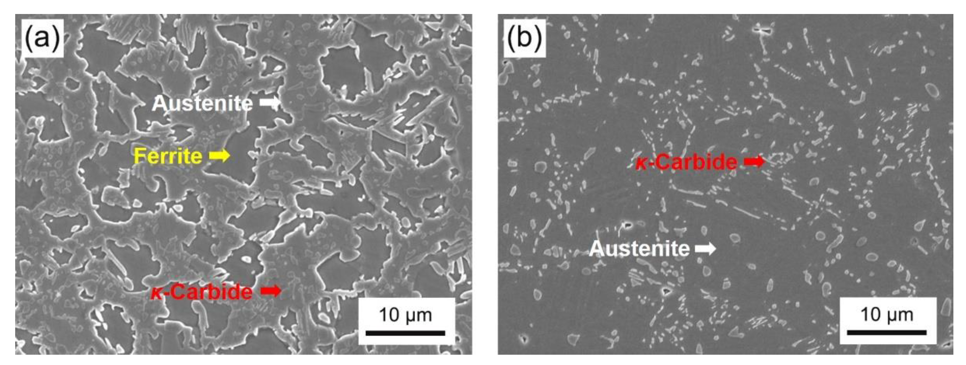
Figure 6. Part ferrite, κ-carbides and austenite exist in the 900 °C-40 min (HSYM-900) sample (Figure 6a). Only a few κ-carbides and austenite exist in the 950 °C-40 min (HSYM-950) sample (Figure 6b). The ferrite in HSYM-900 has an irregular morphology, and the fraction of κ-carbides is significantly higher than that in HSYM-950.
The micrographs of the DET samples are presented in Figure 7, and the XRD results reveal that the composition only includes ferrite and κ-carbide (Figure 8a,b). The κ-carbide distribution becomes more and more uniform in 950 °C-austenitized samples with a decreasing cooling rate, and the spacing of carbides decreases with an increase in cooling rate (Figure 7a–c). Spherical κ-carbides are dominant in the microstructure of HSYM steel, indicating a good spheroidization effect of DET treatment at three cooling rates. However, there are still some lamellar κ-carbides in the samples with the cooling rates of 3 °C·min−1 and 5 °C·min−1. The lamellar κ-carbides are retained from the κ-pearlite structure, which is incompletely spheroidized at a larger cooling rate. On the one hand, since the elements have enough time to diffuse at a lower cooling rate, the spheroidization of κ-carbides is more likely to occur with a decreasing cooling rate. On the other hand, the κ-pearlite transformation at the early stage is more likely to happen at the high cooling rate. Therefore, lamellar κ-carbides are more likely to be retained at a higher cooling rate. As a result, the microstructure of the samples at a higher cooling rate is non-uniform, as exhibited in Figure 7b,c. The relationship between carbide size and cooling rate in Figure 8c clearly reveals that the average size of κ-carbides increases gradually with decreasing cooling rate due to sufficient growth. In addition, the volume fractions of κ-carbide measured by XRD are 23.8%, 30.1% and 21.3% of the samples cooling at the rates of 1, 3 and 5 °C·min−1, respectively (Figure 8a). The fraction of κ-carbides increases first, and then decreases with increasing cooling rate. This is due to the fact that denser lamellar κ-carbides exist in the sample at 3 °C·min−1, and the κ-carbides particles in the sample at 5 °C·min−1 do not have sufficient time for coarsening.
Compared with the microstructure of DET samples with austenitizing temperature of 950 °C (Figure 7a–c), κ-carbide particles with lesser amount but larger size were observed in the DET samples austenitized at 900 °C (Figure 7d–f). For instance, the average size of κ-carbide in the sample 900-1 is 1.86 ± 0.15 μm but 1.58 ± 0.05 μm for the sample 950-1 (Figure 8c). This is mainly due to the existence of ferrite and more undissolved κ-carbides in austenite after austenitizing at 900 °C for 40 min (Figure 6a). These undissolved κ-carbides grow up directly during the subsequent cooling process, leading to an enlarged size and a decreased amount. The carbide spacing is significantly larger than that austenitized at 950 °C. On the one hand, the volume fraction of κ-carbide in samples austenitized at 950 °C is higher, and more κ-carbide particles lead to smaller spacing. On the other hand, the pre-existing ferrite with less κ-carbide particles was inherited. In addition, the size of κ-carbide becomes more uniform in the DET samples austenitized at 900 °C as the cooling rate decreases. Only the sample cooling at 5 °C·min−1 has a few lamellar κ-carbides, while the κ-carbides in the other two samples are well spheroidized (Figure 7d–f). There are two major reasons as follows: (1) The pre-existing ferrite results in an increase in carbide spacing, and thus, the carbides are not easily accumulated during the cooling process. (2) A decrease in austenitizing temperature leads to a decrease in undercooling degree, so that the transformation speed of pearlite decreases. Therefore, only a small number of pearlites appear at the higher cooling rate in the sample austenitized at 900 °C. The volume fractions of κ-carbides measured by XRD are 27.0%, 30.2% and 30.6% for samples cooling at the rates of 1, 3 and 5 °C·min−1, respectively (Figure 8b). The decreased fraction of κ-carbide with decreasing cooling rate is caused by the less time of carbon diffusion into austenite. In addition, the average size of κ-carbide gradually decreases with increasing cooling rate.
Finally, the microstructure evolution diagram during DET is summarized in Figure 9. After austenitizing, the ferrite–austenite transformation occurs completely, and the microstructure is composed of some κ-carbide particles retained in the austenite matrix. When the temperature decreases to about 900 °C, the κ-pearlite and ferrite transformations combined with the growth of κ-carbides commence. With decreasing quenching temperature to 850 °C, the austenite–ferrite transformation is finished, and just the morphology evolution of κ-carbides takes place during the subsequent slow cooling process. There are two types of κ-carbide, namely intergranular κ-carbides and intragranular κ-carbides. The latter are thin particles distributed in ferrite matrix, while those short rod-like carbides are regarded as the production of pearlite spheroidization. When the temperature decreases to about 800 °C, the disappearance of intergranular carbides is due to the spheroidization in the cooling process and the growth of ferrite grains. During this process, κ-carbides are just spheroidized and grow up. As the temperature continues to decrease, the κ-carbides grow up obviously both near grain boundaries and inside grains. However, the spheroidization effect is not ideal as the temperature decreases to about 720 °C due to the existence of strip κ-carbides near grain boundaries. During the subsequent air-cooling process, the strip κ-carbides might be further spheroidized, and the κ-carbides are dispersedly distributed in the ferrite matrix. In addition, the austenitizing temperature mainly influences the fraction of undissolved κ-carbides, and the lower cooling rate is beneficial for a good spheroidization effect.

4. Conclusions

In this work, a 780 MPa grade HSYM steel was developed, and the DET treatment was adopted for ductility improvement. The effects of different cooling rates and austenitizing temperatures on the spheroidization of κ-carbides during the DET process were studied. In addition, the detailed microstructure evolution during DET was characterized to clarify the spheroidization mechanism. The main conclusions are summarized as follows:
  • The studied HSYM steel has a specific Young’s modulus of 29.2 GPa·g−1·cm3 due to the introduction of κ-carbides with a fraction of 26.4 vol.%. The ductility of HSYM-HR significantly improved from 0.9% to 22.3% by an appropriate DET treatment to regulate the κ-carbide morphology;
  • The austenitizing temperature and cooling rate are the critical parameters of DET. The size of κ-carbide increases with a decreasing cooling rate, and the κ-carbide spheroidization effect becomes better at a lower cooling rate. The size of κ-carbide increases, and the fraction of κ-carbide decreases at lower austenitizing temperature due to the existence of more undissolved κ-carbide particles;
  • The microstructure evolution during DET exhibits κ-pearlite transformation at the early stage of slow cooling, which is inconsistent with previous work. The κ-pearlite spheroidization and κ-particle growth take place simultaneously. Eventually, the DET microstructure consisting of spheroidized κ-carbides distributed in the ferrite matrix are obtained.

Author Contributions

Conceptualization, X.L. and P.C.; methodology, X.L. and P.C.; validation, F.Y.; formal analysis, F.Y.; investigation, F.Y.; resources, X.L. and P.C.; writing—original draft preparation, F.Y. and P.C.; writing—review and editing, X.L. and P.C.; supervision, X.L. and P.C.; funding acquisition, X.L. and P.C. All authors have read and agreed to the published version of the manuscript.

Funding

This research was funded by National Natural Science Foundation of China under grant numbers 52171108 and 51804072 and by Fundamental Research Funds for the Central University under grant number N2202007.

Data Availability Statement

The raw/processed data required to reproduce these findings cannot be shared at this time as the data also form part of an ongoing study.

Acknowledgments

Special thanks are also due to the instrumental or data analysis from Analytical and Testing Center, Northeastern University, China.

Conflicts of Interest

The authors declare no conflict of interest.

References

  1. Paxton, D.M.; Carpenter, J.A.; Sklad, P.S.; Smith, M.T. Overview of Lightweighting Materials Research & Development in the United States Freedom car and Fuel Partnership. Mater. Sci. Forum. 2009, 618–619, 395–404. [Google Scholar]
  2. Zuazo, I.; Hallstedt, B.; Lindahl, B.; Selleby, M.; Soler, M.; Etienne, A.; Perlade, A.; Hasenpouth, D.; Massardier, J.V.; Cazottes, S.; et al. Low-Density Steels: Complex Metallurgy for Automotive Applications. JOM 2014, 66, 1747–1758. [Google Scholar] [CrossRef]
  3. Bonnet, F.; Daeschler, V.; Petitgand, G. High modulus steels: New requirement of automotive market. How to take up challenge? Can. Metall. Q. 2014, 53, 243–252. [Google Scholar] [CrossRef]
  4. Soleimani, M.; Kalhor, A.; Mirzadeh, H. Transformation-induced plasticity (TRIP) in advanced steels: A review. Mater. Sci. Eng. A 2020, 795, 140023. [Google Scholar] [CrossRef]
  5. Frommeyer, G.; Drewes, E.J.; Engl, B. Physical and mechanical properties of iron-aluminium-(Mn, Si) lightweight steels. Metall. Res. Technol. 2000, 97, 1245–1253. [Google Scholar] [CrossRef]
  6. Chen, P.; Fu, J.; Xu, X.; Lin, C.; Pang, J.C.; Li, X.W.; Misera, R.D.; Wang, G.D.; Yi, H.L. A high specific Young’s modulus steel reinforced by spheroidal kappa-carbide. J. Mater. Sci. Technol. 2021, 87, 54–59. [Google Scholar] [CrossRef]
  7. Chen, P.; Xu, X.; Lin, C.; Yang, F.M.; Pang, J.C.; Li, X.W.; Yi, H.L. Controlling Carbide Evolution to Improve the Ductility in High Specific Young’s Modulus Steels. Acta Metall. Sin. 2022; in press. [Google Scholar] [CrossRef]
  8. Pang, J.C.; Yang, W.F.; Wang, G.D.; Zheng, S.J.; Misra, R.D.; Yi, H.L. Divorced eutectoid transformation in high-Al added steels due to heterogenous nucleation of κ-carbide. Scripta Mater. 2022, 209, 114395. [Google Scholar] [CrossRef]
  9. Chen, P.; Xiong, X.C.; Wang, G.D.; Yi, H.L. The origin of the brittleness of high aluminum pearlite and the method for improving ductility. Scr. Mater. 2016, 124, 42–46. [Google Scholar] [CrossRef]
  10. Han, D.; Du, L.; Yao, C.; Misra, R.D. The Evolution of Deformation-Induced Carbides during Divorced Eutectoid Transformation in GCr15 Steels. J. Mater. Eng. Perform. 2019, 28, 5277–5288. [Google Scholar] [CrossRef]
  11. Verhoeven, J.D.; Gibson, E.D. The divorced eutectoid transformation in steel. Metall. Mater. Trans. A 1998, 29, 1181–1189. [Google Scholar] [CrossRef]
  12. Verhoeven, J.D. The role of the divorced eutectoid transformation in the spheroidization of 52100 steel. Metall. Mater. Trans. A 2000, 31, 2431–2438. [Google Scholar] [CrossRef]
  13. Ishii, H.; Ohkubo, K.; Miura, S.; Mohri, T. Mechanical Properties of α+κ Two-phase Lamellar Structure in Fe-Mn-Al-C Alloy. Mater. Trans. 2003, 44, 1679–1681. [Google Scholar] [CrossRef]
  14. Li, Y.; Wilson, J.A.; Crowther, D.N.; Mitchell, P.S.; Craven, A.J.; Baker, T.N. The Effects of Vanadium, Niobium, Titanium and Zirconium on the Microstructure and Mechanical Properties of Thin Slab Cast Steels. ISIJ Int. 2004, 44, 1093–1102. [Google Scholar] [CrossRef]
  15. Tong, M.W.; Yuan, Z.X.; Zhang, K.G. Influence of Vanadium on Microstructures and Mechanical Properties of High Strength Normalized Steel. Adv. Mater. Res. 2012, 535–537, 628–632. [Google Scholar] [CrossRef]
  16. Jorge-Badiola, D.; Iza-Mendia, A.; López, B.; Rodriguez, J.M. Role of Vanadium Microalloying in Austenite Conditioning and Pearlite Microstructure in Thermomechanically Processed Eutectoid Steels. ISIJ Int. 2009, 49, 1615–1623. [Google Scholar] [CrossRef] [Green Version]
  17. Pang, J.C.; Chen, P.; Wang, G.D.; Yi, H.L. Mechanism of divorced eutectoid transformation: Pearlitic transformation combined with dynamic spheroidization. Acta Mater. 2022; submitted. [Google Scholar]
Figure 1. (a) The thermodynamic phase diagram; (b) DET heat treatment process; (c) the staged quenching process.
Crystals 12 01372 g001
Figure 2. (a) SEM image of the microstructure in HSYM-HR; (b) engineering stress–strain curves of HSYM-HR and HSYM-DET; (c) SEM image of the fracture surface morphology of HSYM-HR; (d) XRD pattern of HSYM-HR.
Crystals 12 01372 g002
Figure 3. SEM images showing the microstructure (a) and the fracture surface morphology (b) of HSYM-DET.
Crystals 12 01372 g003
Figure 4. SEM micrographs showing the microstructures in the samples subjected to staged quenching from 900 °C (a), 850 °C (b), 800 °C (c), 750 °C (d), 730 °C (e) and 720 °C (f), and the relevant high-resolution observations of the samples subjected to staged quenching from 850 °C (g) and 800 °C (h).
Crystals 12 01372 g004
Figure 5. SEM images (a,c) of the carbides and the relevant EPMA analyses (b,d) of their chemical compositions in the samples quenched in stages to 750 °C, (a,b) intergranular carbides, (c,d) intragranular carbides.
Crystals 12 01372 g005
Figure 6. SEM images showing the microstructures in HSYM steels at different austenitizing temperatures: (a) 900 °C-40 min, (b) 950 °C-40 min.
Crystals 12 01372 g006
Figure 7. SEM images showing the microstructures in the samples after DET heat treatment at different cooling rates: (a) 950-1, (b) 950-3, (c) 950-5, (d) 900-1, (e) 900-3 and (f) 900-5.
Crystals 12 01372 g007
Figure 8. XRD patterns of HSYM steels cooled at different rates and austenitized at 950 °C (a) and 900 °C (b), together with the average size of κ-carbides in the samples austenitized at 950 °C and 900 °C (c).
Crystals 12 01372 g008
Figure 9. Schematic diagram showing the microstructure evolution in the HSYM steel during DET.
Crystals 12 01372 g009
Publisher’s Note: MDPI stays neutral with regard to jurisdictional claims in published maps and institutional affiliations.

