

Development and Prospect of Viewing Angle Switchable Liquid Crystal Devices


Abstract
1. Introduction
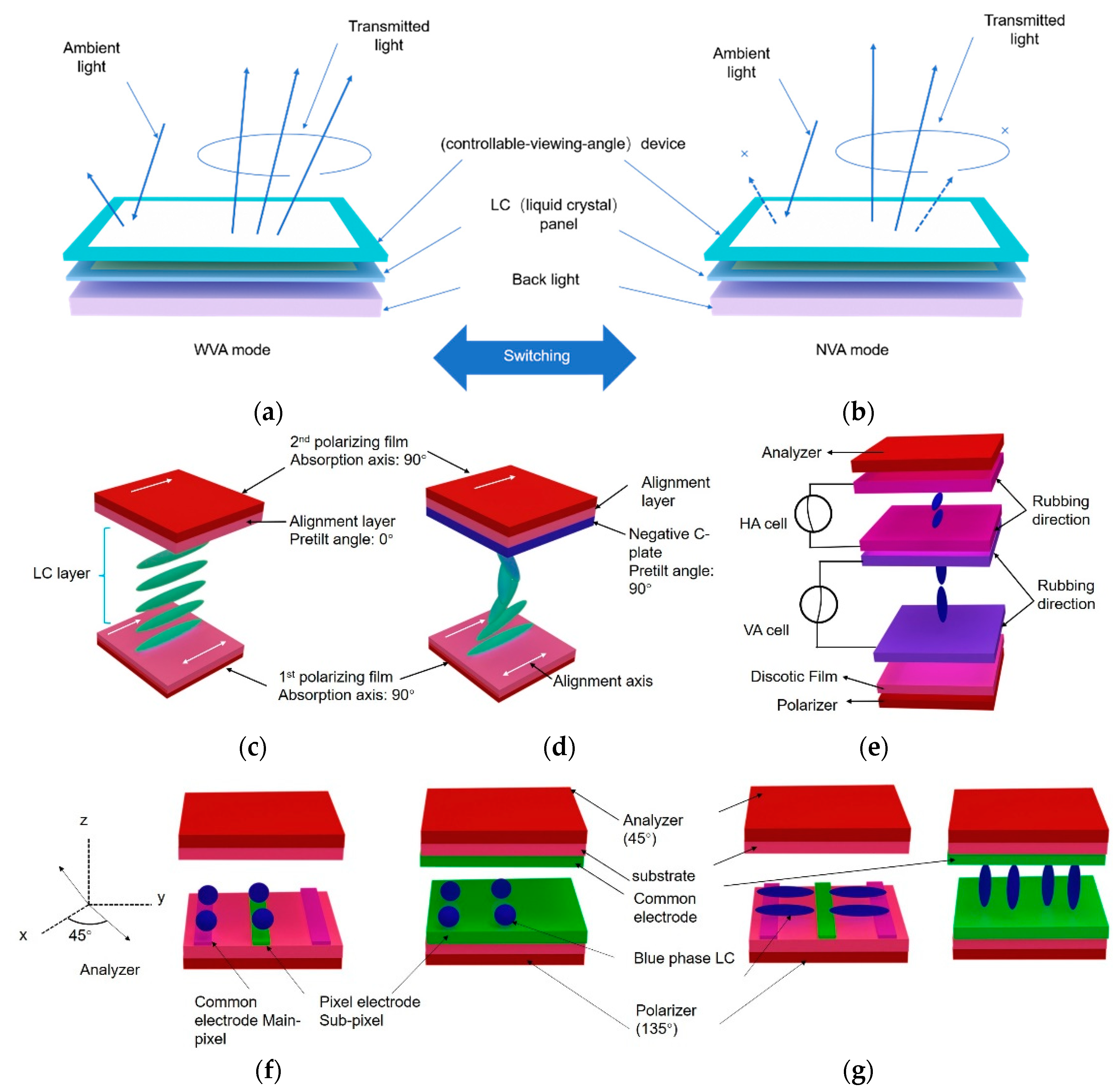
2. Pure LC Devices
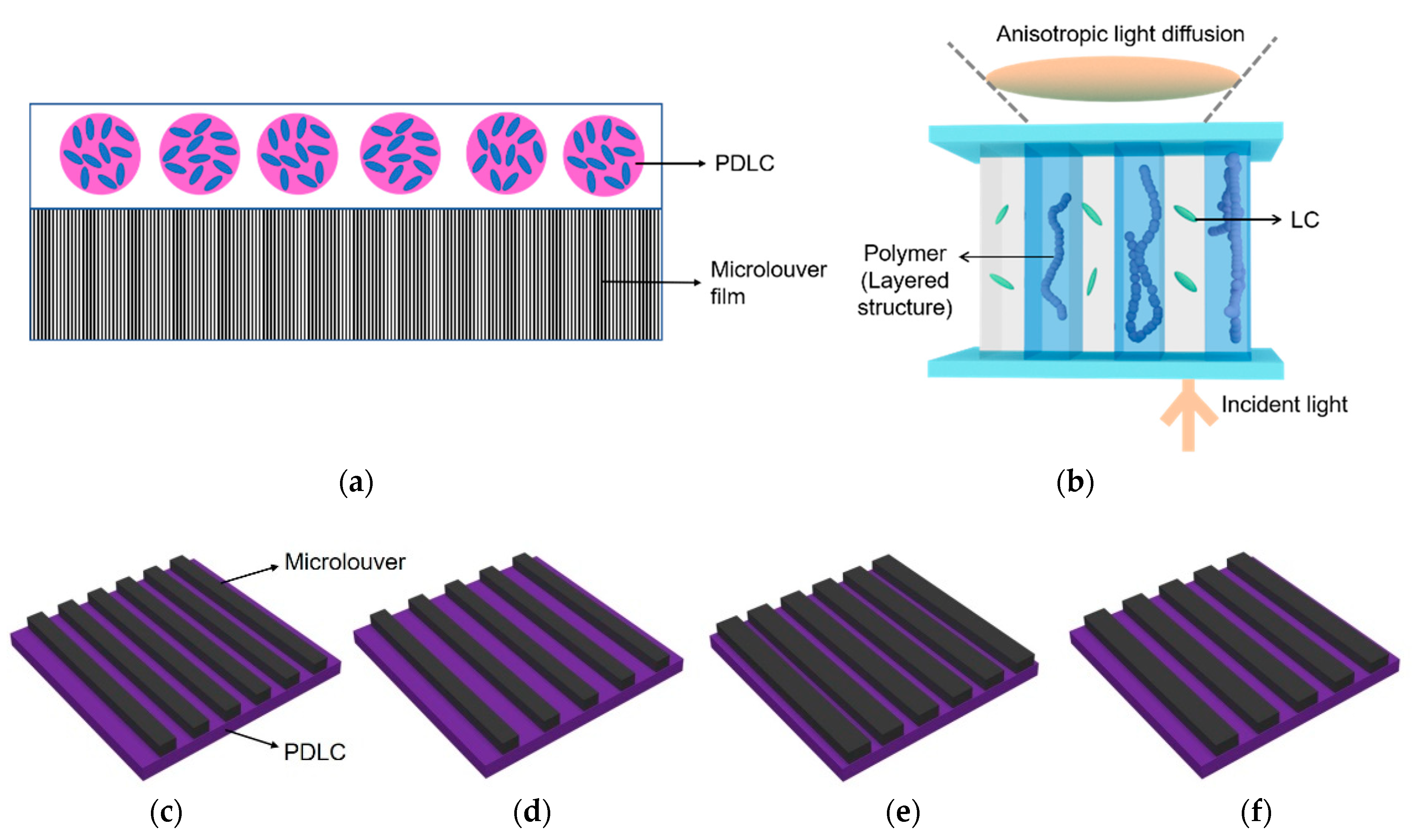
3. PDLC Devices
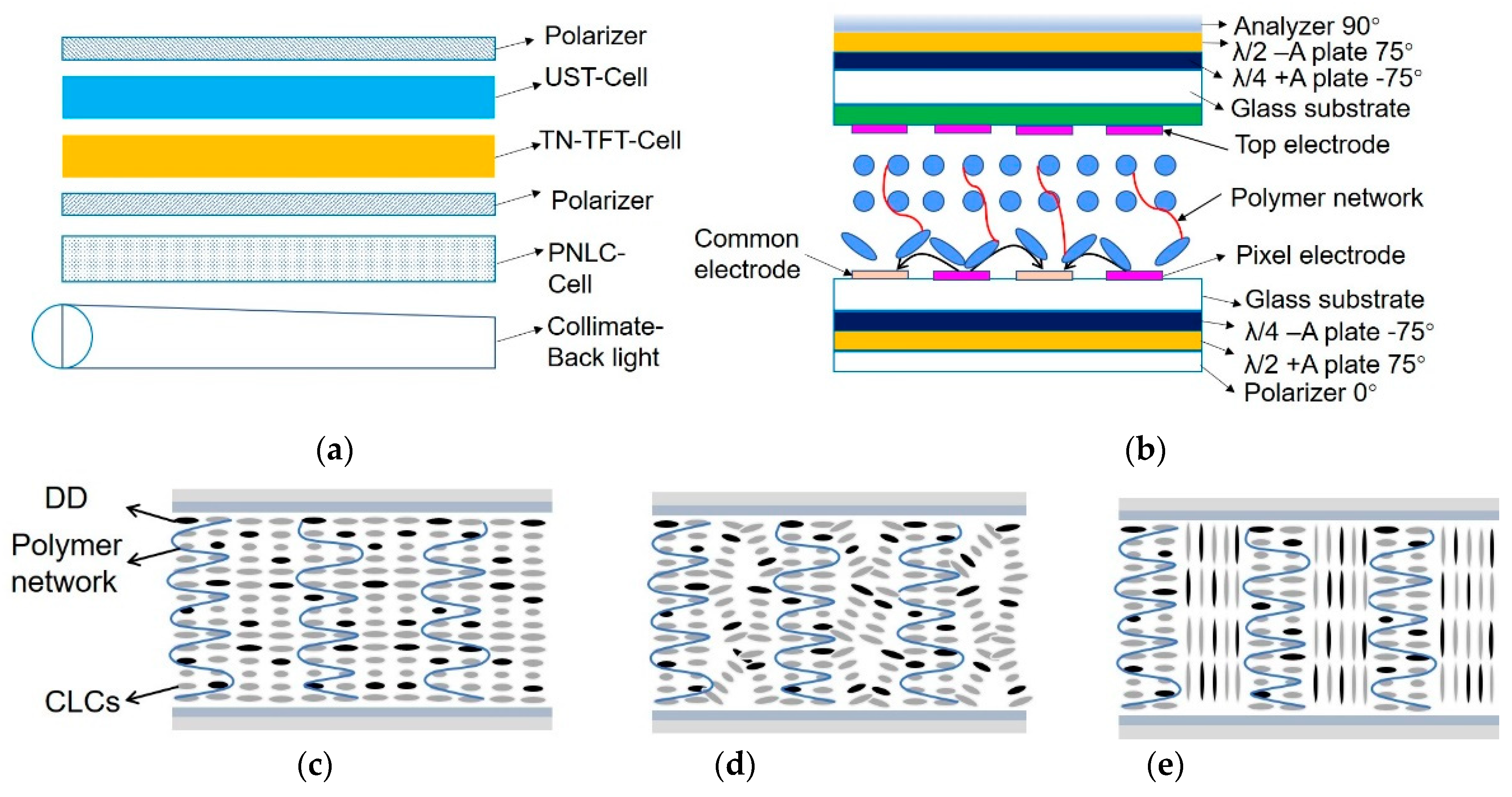
4. PSLC/PNLC Devices
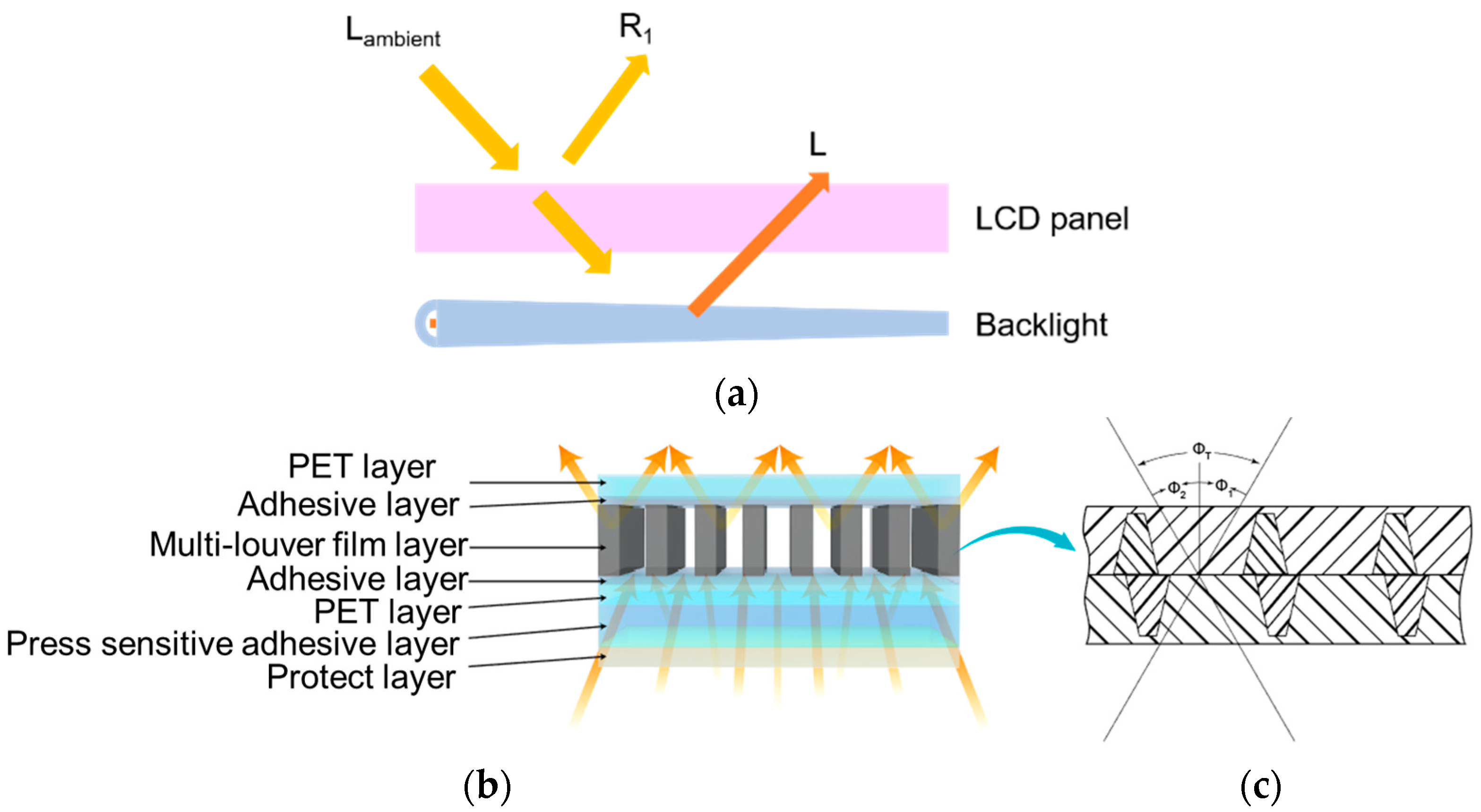
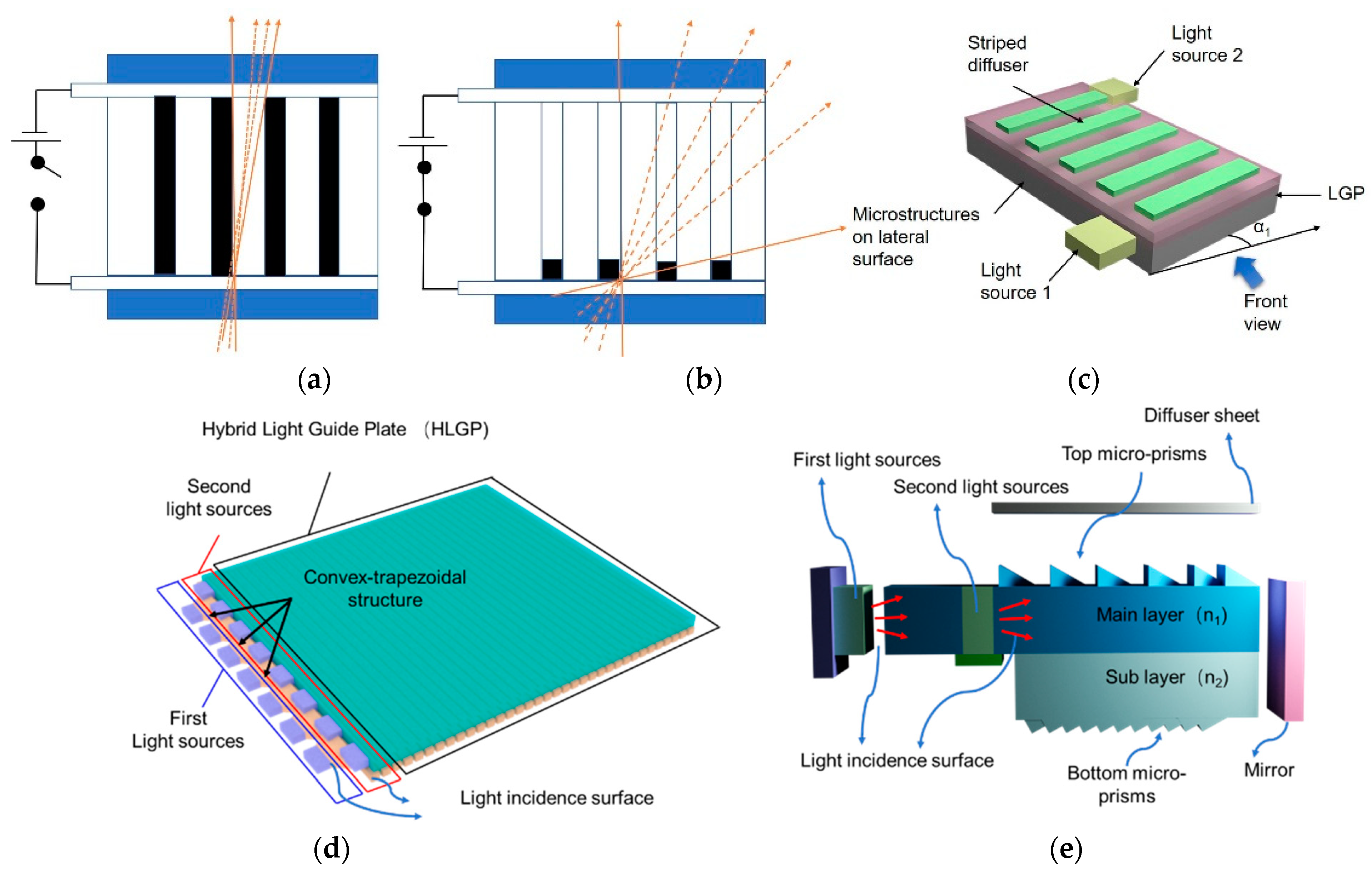
5. Non-LC Devices
6. Discussion
7. Conclusions and Perspective
Author Contributions
Funding
Institutional Review Board Statement
Informed Consent Statement
Data Availability Statement
Conflicts of Interest
References
- Chen, C.P.; Jhun, C.G.; Yoon, T.H.; Kim, J.C. Viewing angle switching of tristate liquid crystal display. Jpn. J. Appl. Phys. 2007, 46, L676–L678. [Google Scholar] [CrossRef]
- Chen, C.P.; Kim, K.H.; Yoon, T.H.; Kim, J.C. A viewing angle switching panel using guest-host liquid crystal. Jpn. J. Appl. Phys. 2009, 48, 062401. [Google Scholar] [CrossRef]
- Her, J.H.; Shin, S.J.; Lim, Y.J.; Bhattacharyya, S.S.; Kang, W.S.; Lee, G.D.; Lee, S.H. Viewing angle switching in in-plane switching liquid crystal display. Mol. Cryst. Liq. Cryst. 2011, 544, 220–226. [Google Scholar] [CrossRef]
- Chen, H.W.; Tan, G.J.; Wu, S.T. Ambient contrast ratio of LCDs and OLED displays. Opt. Express 2017, 25, 33643–33656. [Google Scholar] [CrossRef]
- Jo, S.I.; Lee, S.G.; Lee, Y.J.; Kim, J.H.; Yu, C.J. Viewing angle controllable liquid crystal display under optical compensation. Opt. Eng. 2011, 50, 094003. [Google Scholar] [CrossRef]
- Chiu, R.C. Light Control Device. U.S. Patent 6398370, 4 June 2002. [Google Scholar]
- Baek, J.I.; Kim, K.H.; Kim, J.C.; Yoon, T.H. Viewing angle control of a hybrid-aligned liquid crystal display. Mol. Cryst. Liq. Cryst. 2009, 498, 103–109. [Google Scholar] [CrossRef]
- Shiota, K.; Okamoto, M.; Tanabe, H. 76-3: Distinguished Paper: Viewing-angle-switching device based on array of optical micro-rod incorporated with electrophoretic material systems. SID Symp. Dig. Tech. Pap. 2017, 48, 1117–1120. [Google Scholar] [CrossRef]
- Chen, B.T.; Pan, J.W.; Hu, Y.W.; Tu, S.H.P. 50: Design of a novel hybrid light guide plate for viewing angle switchable backlight module. SID Symp. Dig. Tech. Pap. 2013, 44, 1181–1184. [Google Scholar] [CrossRef]
- Kim, M.S.; Lim, Y.J.; Yoon, S.; Kang, S.W.; Lee, S.H.; Kim, M.; Wu, S.T. A controllable viewing angle LCD with an optically isotropic liquid crystal. J. Phys. D Appl. Phys. 2010, 43, 145502. [Google Scholar] [CrossRef]
- Kim, M.S.; Lim, Y.J.; Yoon, S.; Kim, M.K.; Kumar, P.; Kang, S.W.; Kang, W.S.; Lee, G.D.; Lee, S.H. Luminance-controlled viewing angle-switchable liquid crystal display using optically isotropic liquid crystal layer. Liq. Cryst. 2011, 38, 371–376. [Google Scholar] [CrossRef]
- Lim, Y.J.; Jeong, E.; Kim, Y.S.; Jeong, Y.H.; Jang, W.G.; Lee, S.H. Viewing angle switching in fringe-field switching liquid crystal display. Mol. Crystal. Liq. Cryst. 2008, 495, 186. [Google Scholar] [CrossRef]
- Lim, Y.J.; Kim, J.H.; Her, J.H.; Bhattacharyya, S.S.; Park, K.H.; Lee, J.H.; Kim, B.K.; Lee, S.H. Viewing angle controllable liquid crystal display with high transmittance. Opt. Express 2010, 18, 6824–6830. [Google Scholar] [CrossRef]
- Adachi, M. Controllable-viewing-angle display using a hybrid aligned nematic liquid-crystal cell. Jpn. J. Appl. Phys. 2008, 47, 7920–7925. [Google Scholar] [CrossRef]
- Adachi, M.; Shimura, M. P-228L: Late-News Poster: Controllable Viewing-Angle Displays using a Hybrid Aligned Nematic Liquid Crystal Cell. SID Symp. Dig. Tech. Pap. 2006, 37, 705–708. [Google Scholar] [CrossRef]
- Jeong, E.; Lim, Y.J.; Rhee, J.M.; Lee, S.H.; Lee, G.D.; Park, K.H.; Choi, H.C. Viewing angle switching of vertical alignment liquid crystals by controlling birefringence of homogeneously aligned liquid crystal layer. Appl. Phys. Lett. 2007, 90, 051116. [Google Scholar] [CrossRef]
- Jeong, E.; Lim, Y.J.; Chin, M.H.; Kim, J.H.; Lee, S.H.; Ji, S.H.; Lee, G.D.; Park, K.H.; Choi, H.C.; Ahn, B.C. Viewing-angle controllable liquid crystal display using a fringe- and vertical-field driven hybrid aligned nematic liquid crystal. Appl. Phys. Lett. 2008, 92, 261102. [Google Scholar] [CrossRef]
- Li, Y.F.; Sun, Y.B.; Zhao, Y.L.; Li, P.; Ma, H.M. A continuous viewing angle controllable blue phase liquid crystal display. J. Disp. Technol. 2014, 10, 799–803. [Google Scholar] [CrossRef]
- Kim, Y.T.; Hong, J.H.; Cho, S.M.; Lee, S.D. Viewing angle switchable liquid crystal display with double layers separated by an interlayer support. Jpn. J. Appl. Phys. 2009, 48, 110205. [Google Scholar] [CrossRef]
- Gwag, J.S.; Lee, Y.J.; Kim, M.E.; Kim, J.H.; Kim, J.C.; Yoon, T.H. Viewing angle control mode using nematic bistability. Opt. Express 2008, 16, 2663–2669. [Google Scholar] [CrossRef]
- Rao, L.H.; Ge, Z.B.; Wu, S.T. Viewing angle controllable displays with a blue-phase liquid crystal cell. Opt. Express 2010, 18, 3143–3148. [Google Scholar] [CrossRef]
- Baek, J.I.; Kim, K.H.; Lee, S.R.; Kim, J.C.; Yoon, T.H. Viewing angle control of a fringe-field switching cell by electrical tilting of liquid crystal. Jpn. J. Appl. Phys. 2008, 47, 1615–1617. [Google Scholar] [CrossRef]
- Sun, Y.B.; Li, Y.F.; Zhao, Y.L.; Li, P.; Ma, H.M. A low voltage and continuous viewing angle controllable blue phase liquid crystal display. J. Disp. Technol. 2014, 10, 484–487. [Google Scholar] [CrossRef]
- Yu, Y.N.; Dou, H.; Ma, H.M.; Sun, Y.B. Continuous viewing angle controllable patterned vertical alignment liquid crystal display. Liq. Cryst. 2014, 41, 1595–1599. [Google Scholar] [CrossRef]
- Yu, Y.N.; Dou, H.; Ma, H.M.; Sun, Y.B. Viewing angle controllable fringe and inplane switching vertical alignment LCD. Liq. Cryst. 2015, 42, 316–321. [Google Scholar] [CrossRef]
- Hu, D.; Chen, M.; Li, D.; Yu, G.; Sun, Y.B. A controllable viewing angle optical film using micro prisms filled with liquid crystal. Liq. Cryst. 2021, 48, 1373–1381. [Google Scholar]
- Gwag, J.S.; Han, I.Y.; Yu, C.J.; Choi, H.C.; Kim, J.H. Continuous viewing angle-tunable liquid crystal display using temperature-dependent birefringence layer. Opt. Express 2009, 17, 5426–5432. [Google Scholar] [CrossRef]
- Gwag, J.S.; Lee, Y.J.; Han, I.Y.; Yu, C.J.; Kim, J.H. LCD with tunable viewing angle by thermal modulation of optical layer. J. Inf. Disp. 2009, 10, 19–23. [Google Scholar] [CrossRef]
- Han, I.Y.; Gwag, J.S.; Lee, Y.J.; Yu, C.J.; Kim, J.H. Viewing angle controllable liquid crystal display by thermally variable retardation layer. Mol. Cryst. Liq. Cryst. 2009, 507, 122–128. [Google Scholar] [CrossRef]
- Choi, H.J.; Lee, H.S.; Lim, S.H.; Park, S.Y.; Baek, S.K.; Lee, J.H. Dependence of the viewing angle control property of a guest-host liquid crystal cell on the extinction coefficient of the mixture. Appl. Opt. 2019, 58, 6105–6111. [Google Scholar] [CrossRef]
- Zhou, L.; He, Z.M.; Han, C.; Zhang, L.Y.; Yang, H. Switchable anti-peeping film for liquid crystal displays from polymer dispersed liquid crystals. Liq. Cryst. 2019, 46, 718–724. [Google Scholar] [CrossRef]
- Ishinabe, T.; Horii, Y.; Shibata, Y.; Fujikake, H. Structured PDLCs for controlling LCD viewing-angle. Dig. Tech. Pap. 2018, 49, 546–549. [Google Scholar] [CrossRef]
- Han, C.; Zhou, L.; Ma, H.P.; Li, C.Y.; Zhang, S.F.; Cao, H.; Zhang, L.Y.; Yang, H. Fabrication of a controllable anti-peeping device with a laminated structure of microlouver and polymer dispersed liquid crystals film. Liq. Cryst. 2019, 46, 2235–2244. [Google Scholar] [CrossRef]
- He, Z.M.; Shen, W.B.; Yu, P.; Zhao, Y.Z.; Zeng, Z.; Liang, Z.; Chen, Z.; Zhang, H.M.; Zhang, H.Q.; Miao, Z.C.; et al. Viewing-angle-switching film based on polymer dispersed liquid crystals for smart anti-peeping liquid crystal display. Liq. Cryst. 2022, 49, 59–65. [Google Scholar] [CrossRef]
- Hisatake, Y.; Kawata, Y.; Murayama, A. Viewing angle controllable LCD using variable optical compensator and variable diffuser. SID Sym. Dig. Tech. Pap. 2005, 36, 1218–1221. [Google Scholar] [CrossRef]
- Li, P.; Sun, Y.B.; Wang, Q.H. A transflective and viewing angle controllable blue-phase liquid crystal display. Liq. Cryst. 2013, 40, 1024–1027. [Google Scholar] [CrossRef]
- Liu, L.W.; Cui, J.P.; Li, D.H.; Wang, Q.H. A viewing-angle-controllable blue-phase liquid-crystal display. J. SID 2012, 20, 337–340. [Google Scholar]
- Yang, H.; Zhou, L.; Ma, H.; Han, C.; Hu, W.; Zhang, L.Y. Electric Control Dimming Film for Use in Display, Has First Composite Material Area Formed by Dye Molecules and Polymer Network, Where First and Second Composite Material Areas Are Formed in Material Film Layer along Vertical Direction. Chinese Patent CN201710456245.9, 6 September 2019. [Google Scholar]
- Shiota, K.; Okamoto, M.; Tanabe, H. Viewing-angle-switching device based on array of optical micro-rods incorporated with electrophoretic material systems. J. Soc. Inf. Disp. 2017, 25, 76–82. [Google Scholar] [CrossRef]
- Wang, Y.J.; Lu, J.G.; Chao, W.C. P-76: Distinguished Student Poster: Viewing Angle Switchable Display with a Compact and Directional Backlight Module. SID Symp. Dig. Tech. Pap. 2014, 45, 1270–1273. [Google Scholar] [CrossRef]
- Wang, Y.J.; Lu, J.G.; Chao, W.C.; Shieh, H.P.D. Switchable viewing angle display with a compact directional backlight and striped diffuser. Opt. Express 2015, 23, 21443–21454. [Google Scholar] [CrossRef]


| Types | Principles | WVA/ Contrast Ratio | WVA/ Viewing Angle | NVA/ Contrast Ratio | NVA/ Viewing Angle | References |
|---|---|---|---|---|---|---|
| LC devices | Pixel division | >10:1 | 50° | 10:1 | 20° | 10 |
| Optically isotropic LC | / | 120° polar angle | / | 35° | 11 | |
| Homogeneous aligned LC layer | 10:1 | 170° | 2:1 | 60° | 16 | |
| Electrical tilting of LC | 10:1 | ±70° | 10:1 | ±10° | 21 | |
| TVRL | 10:1 | 80° polar angle | 10:1 | 20° | 28 | |
| 3M/PDLC | / | ±60° | / | ±30° | 30 | |
| Microlouver/PDLC | / | ±62° | / | ±39° | 32 | |
| PSBPLC | / | 100° | / | 30° | 37 | |
| Non-LC devices | Dual light source | / | 140° | / | 60° | 9 |
| Optical micro-rods | / | / | / | ±30° | 38 | |
| Striped diffuser | / | ±55° | / | ±10° | 41 |
| Types | Privacy Effect | Privacy Viewing Angle | Thickness | Power | Application |
|---|---|---|---|---|---|
| LC devices | Excellent | Horizontal perspective | Thin | High | Monitors |
| Non-LC devices | Moderate | Horizontal perspective | Thick | Moderate | ATMs |
Publisher’s Note: MDPI stays neutral with regard to jurisdictional claims in published maps and institutional affiliations. |
© 2022 by the authors. Licensee MDPI, Basel, Switzerland. This article is an open access article distributed under the terms and conditions of the Creative Commons Attribution (CC BY) license (https://creativecommons.org/licenses/by/4.0/).
Share and Cite
Zhou, L.; Liu, S. Development and Prospect of Viewing Angle Switchable Liquid Crystal Devices. Crystals 2022, 12, 1347. https://doi.org/10.3390/cryst12101347
Zhou L, Liu S. Development and Prospect of Viewing Angle Switchable Liquid Crystal Devices. Crystals. 2022; 12(10):1347. https://doi.org/10.3390/cryst12101347
Chicago/Turabian StyleZhou, Le, and Sijie Liu. 2022. "Development and Prospect of Viewing Angle Switchable Liquid Crystal Devices" Crystals 12, no. 10: 1347. https://doi.org/10.3390/cryst12101347
APA StyleZhou, L., & Liu, S. (2022). Development and Prospect of Viewing Angle Switchable Liquid Crystal Devices. Crystals, 12(10), 1347. https://doi.org/10.3390/cryst12101347