Review

Non-Platinum Group Metal Oxygen Reduction Catalysts for a Hydrogen Fuel Cell Cathode: A Mini-Review

Chemical Engineering Department, New Mexico Tech, Socorro, NM 87801, USA
*
Author to whom correspondence should be addressed.
Catalysts 2025, 15(6), 588; https://doi.org/10.3390/catal15060588
Submission received: 11 April 2025 / Revised: 6 June 2025 / Accepted: 8 June 2025 / Published: 13 June 2025
(This article belongs to the Special Issue Feature Review Papers in Electrocatalysis)

Abstract

:
Although platinum-based catalysts are highly effective for the oxygen reduction reaction (ORR) in proton exchange membrane fuel cells (PEMFCs), their high cost and scarcity limit large-scale commercialization. As a result, platinum group metal-free catalysts—particularly Fe-N-C materials—have received increasing attention as promising alternatives. Despite significant progress, no platinum-group metal-free (PGM-free) catalyst has yet matched the performance and durability of commercial Pt/C in acidic media. Recent advances in synthesis strategies, however, have led to notable improvements in the activity, stability, and active site density of Fe-N-C catalysts. This review highlights key synthesis approaches, including pyrolysis, MOF-derived templates, and cascade anchoring, and discusses how these methods contribute to improved nitrogen coordination, electronic structure modulation, and active site engineering. The continued refinement of these strategies, alongside improved catalyst screening techniques, is essential for closing the performance gap and enabling the practical deployment of non-PGM catalysts in PEMFC technologies.

1. Introduction

To limit the effect of climate change in the future, it is essential that major changes in sectors producing massive amounts of greenhouse gases are made, with the transportation sector being one of these areas. A total of 98% of the vehicles registered in the US in 2022 were gasoline vehicles [1]. These engines produce a vast amount of air pollution and require gasoline, which is fuel made from non-renewable crude oil and other petroleum liquids [2]. A typical internal combustion-powered vehicle emits about 4.6 metric tons of carbon dioxide per year, and 400 g of CO2 per mile is emitted by a passenger vehicle [3]. The greenhouse effect is the process where heat is trapped near the Earth’s surface due to greenhouse gases such as carbon dioxide and methane [4]. The greenhouse effect that greenhouse gases produce has led to a rapidly increasing surface temperature, which has caused sea levels to rise, extreme weather patterns, and habitat destruction [5]. Additionally, crude oil reserves are set to run out in approximately 50 years [6]. Carbon dioxide is at the highest levels ever recorded in the atmosphere and is a leading contributor to the climate change crisis. The reduction of emissions that would result from the reduced consumption of petroleum is integral to maintaining the integrity of our environment [7].
A fuel cell electric vehicle (FCEV) operating on hydrogen only emits water vapor and does not directly emit any CO2 [3]. Since PEMFC-powered vehicles rely solely on hydrogen gas, the production method used to obtain it is the determining factor in the CO2-equivalent emissions of a PEMFC-powered vehicle [8]. Another limiting factor of PEMFCs is the amount of hydrogen available for use in the transportation sector and the limited infrastructure for refueling stations [9]. Increasing the amount of hydrogen produced annually would allow for the expansion of the emission-free vehicle market. The switch to emission-free vehicles would result in increased vehicle efficiency and reduce the sheer volume of petroleum used in the transportation sector. Competition with internal combustion engine vehicles lies in the cost, accessibility, and durability of PEMFC-powered vehicles [10].
Previous and current generations of commercial FCEVs use Pt/C and Pt-Co/C catalysts, respectively. As of 2021, the commercial Toyota Mirai Pt-Co/C catalyst reported a Pt loading of 0.33 mgPt cm−2 for the cathode [11]. Pt-Co/C catalysts, while highly efficient under optimized conditions, are susceptible to performance losses due to carbon monoxide (CO) poisoning and ionomer interaction issues. Their effectiveness depends heavily on precise control of the Pt shell thickness, crystal structure, and the architecture of the carbon support, which must balance accessibility for reactants with protection against ionomer poisoning. Although innovations like mesoporous carbon supports (e.g., HSC-f) have improved Pt utilization and reduced loading requirements, these systems still face limitations related to CO tolerance and mass transport under certain conditions [12]. This reliance on high Pt loading is especially problematic in high-temperature PEMFCs (HT-PEMFCs), where loadings often exceed 1.0 mg Pt/cm2 due to challenges like electrolyte flooding and anion adsorption, which further highlights the need for more CO-tolerant and cost-effective alternatives [13].
In contrast, Fe-N-C catalysts have emerged as a promising class of PGM-free materials for the oxygen reduction reaction (ORR) [14,15]. These catalysts typically feature atomically dispersed Fe-N4 moieties coordinated within a nitrogen-doped carbon matrix. While they offer notable cost and performance advantages, challenges remain in achieving long-term durability in acidic PEMFC conditions, clearly identifying the active sites, and mitigating structural degradation over time. These structure–performance limitations are discussed in greater detail in the Synthesis Strategies Section of this review. These catalysts exhibit strong intrinsic tolerance to CO poisoning, making them more robust under practical fuel cell operating conditions where impurities are present, including trace CO potentially introduced through reformate use or ambient air exposure in real-world environments [16]. Moreover, Fe-N-C materials offer a significant cost advantage and can be synthesized with tunable porosity and active site distribution, supporting efficient mass transport and catalytic activity without the need for scarce and expensive noble metals [14]. This makes Fe-N-C catalysts an attractive and sustainable alternative to Pt-Co/C systems for future fuel cell applications.
This review provides a focused assessment of Fe-N-C catalysts specifically within the context of FCEV deployment, emphasizing their structural characteristics, synthesis strategies, and tolerance to air-derived impurities like CO. By directly comparing these materials to commercial Pt-based catalysts and highlighting recent advances in Fe-N-C performance under acidic PEMFC conditions, this work aims to bridge a critical gap in the literature and support the development of durable, cost-effective PGM-free alternatives for transportation applications.

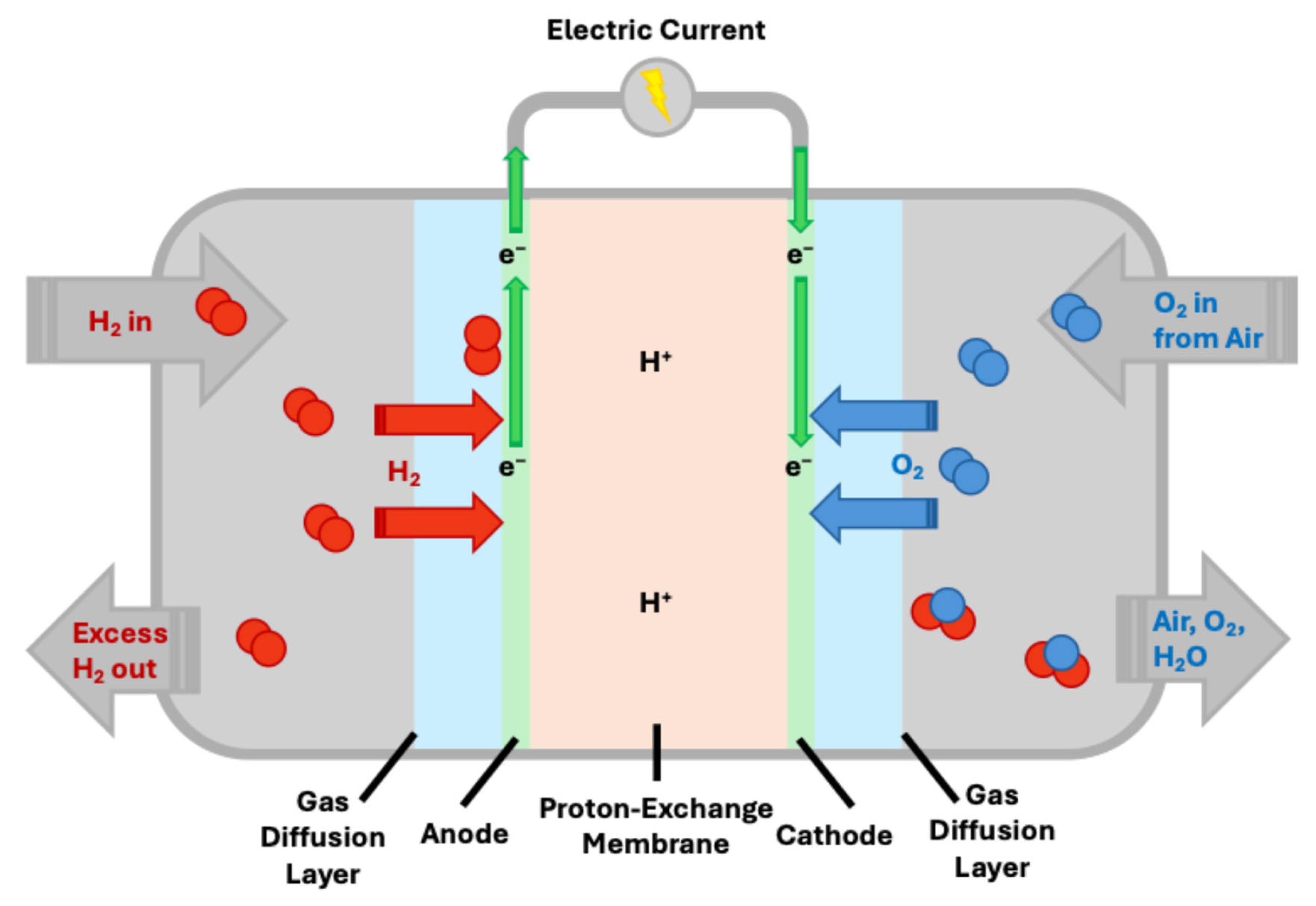
2. Fundamental Aspects of Fuel Cells and ORR

Proton exchange membrane fuel cells (PEMFCs) directly convert the chemical energy in hydrogen to electricity with pure water and heat as byproducts. Specifically, a hydrogen fuel cell is an electrochemical cell that uses a spontaneous redox reaction to produce current. The two sandwiched electrodes with an electrolyte, shown in Figure 1, are the anode and the cathode. All potentials reference the Standard Hydrogen Electrode (SHE), which is defined as 0 V under standard conditions (1 atm H2, 1 M H+, 25 °C). The half-cell and general redox reactions are as follows:
Anodic   Reaction   ( Hydrogen   Oxidation   Reaction ) H 2 2 H + + 2 e E a o = 0 V   ( v s S H E ) Cathodic   Reaction   ( Oxygen   Reduction   Reaction ) O 2 + 4 H + + 4 e 2 H 2 O E c o = 1.23 V   ( v s S H E ) Overall   Reaction 2 H 2 + O 2 2 H 2 O E o = 1.23 V   ( v s S H E )
where the standard electromotive power is 1.23 V, and E a o , and E c o are the anodic and cathodic standard electromotive force, respectively.
Catalysts facilitate the overall reaction between hydrogen fuel and oxygen from the air to produce water vapor. Without a catalyst, the reaction would not be able to produce a usable amount of electricity [17]. As the cathode has sluggish reaction kinetics and catalyst stability issues, our focus will be on the cathode-side reaction (oxygen reduction reaction) and its catalyst.

Oxygen Reduction Reaction

With the oxygen molecule converting into water with an overall four-electron transfer, it is highly exothermic. However, since 1.23 V is required to enable this reaction, it is hard to enable this reaction with sluggish kinetics without a suitable catalyst. A catalyst is needed to lower the amount of potential required to make this reaction occur. The oxygen reduction reaction can occur in a direct four-electron transfer or a series of two-electron transfers and is shown below for acidic media [17]:
Direct   Pathway O 2 + 4 H + + 4 e 2 H 2 O E o = 1.23 V   ( v s S H E ) Series   Pathway O 2 + 2 H + + 2 e H 2 O 2 E o = 0.69 V   ( v s S H E ) H 2 O 2 + 2 H + + 2 e 2 H 2 O E o = 1.77 V   ( v s S H E )
The direct pathway is the most favorable as it involves the breaking of the O-O bond of the oxygen molecule and provides the most released free energy. For complete oxygen reduction, the catalyst should be able to generate H2O from O2 through the direct pathway with minimal H2O2 production. The series pathway discharges nearly half of the free energy compared to the direct pathway because of the high energy required to break the O-O bond. The series pathway introduces harmful free radical species into the electrolyte while also providing lower energy conversion efficiency [17].

3. Synthesis Strategies and Material Design of Non-PGM ORR Catalysts

Expensive platinum-based catalysts are currently used on both electrodes of a proton exchange membrane fuel cell (PEMFC). On top of being expensive and precious, platinum-based catalysts are not considered perfect for both electrodes (the cathode and the anode). The cathode suffers from sluggish ORR kinetics, which leads to declining activity, methanol crossover, and CO poisoning effects [18,19,20]. The cathode reaction involves the reduction of an oxygen molecule and has been a major barrier to the development of economically enticing technology [19]. This poor ORR activity and low stability, coupled with the high price of platinum catalysts, limit the mass commercialization of PEM fuel cells with the current technology. Over the last few decades, much research has been undertaken to find a suitable alternative that offers the same, if not better, integrity and stability as the standard platinum-based catalysts [21]. Finding a suitable alternative to platinum-based catalysts has been a great challenge since no catalyst has currently surpassed platinum-based catalysts in integrity, stability, and oxygen reduction (ORR) performance [22,23]. Many platinum-free metal-based catalysts have been investigated to find a catalyst that can balance between ORR activity, electron conductivity, stability, and O2 transport [24,25]. The most common categories of PGM-free catalysts for acidic ORR include iron–nitrogen–carbon (Fe-N-C) [26], carbon-based [27], and other molecular catalysts [28,29]. Studies showing Fe-N4 moieties or Fe-N4 coordination environments have been shown to have particularly high ORR activity, and well-defined Fe-N bonding sites serve as highly active and stable centers [30,31]. Beyond the density of Fe-Nx sites, their accessibility and exposure at the catalyst surface play a critical role in determining ORR activity. These structures are common across both Fe-N-C materials and molecular macrocycles, offering a strong link between heterogeneous and homogeneous catalyst design [32]. Q. Wang et al. demonstrated that lower catalyst loading led to increased H2O2 yield, indicating that inner Fe sites are less utilized, likely due to mass transport or site accessibility limitations [33]. This suggests that catalytic performance may be limited not by the presence of Fe-Nx moieties but by their availability at the reaction interface. In contrast, 2D catalysts, such as g-FePc [28], may suffer less from these limitations due to their atomically thin structure, which could facilitate greater exposure of active sites and more uniform utilization.

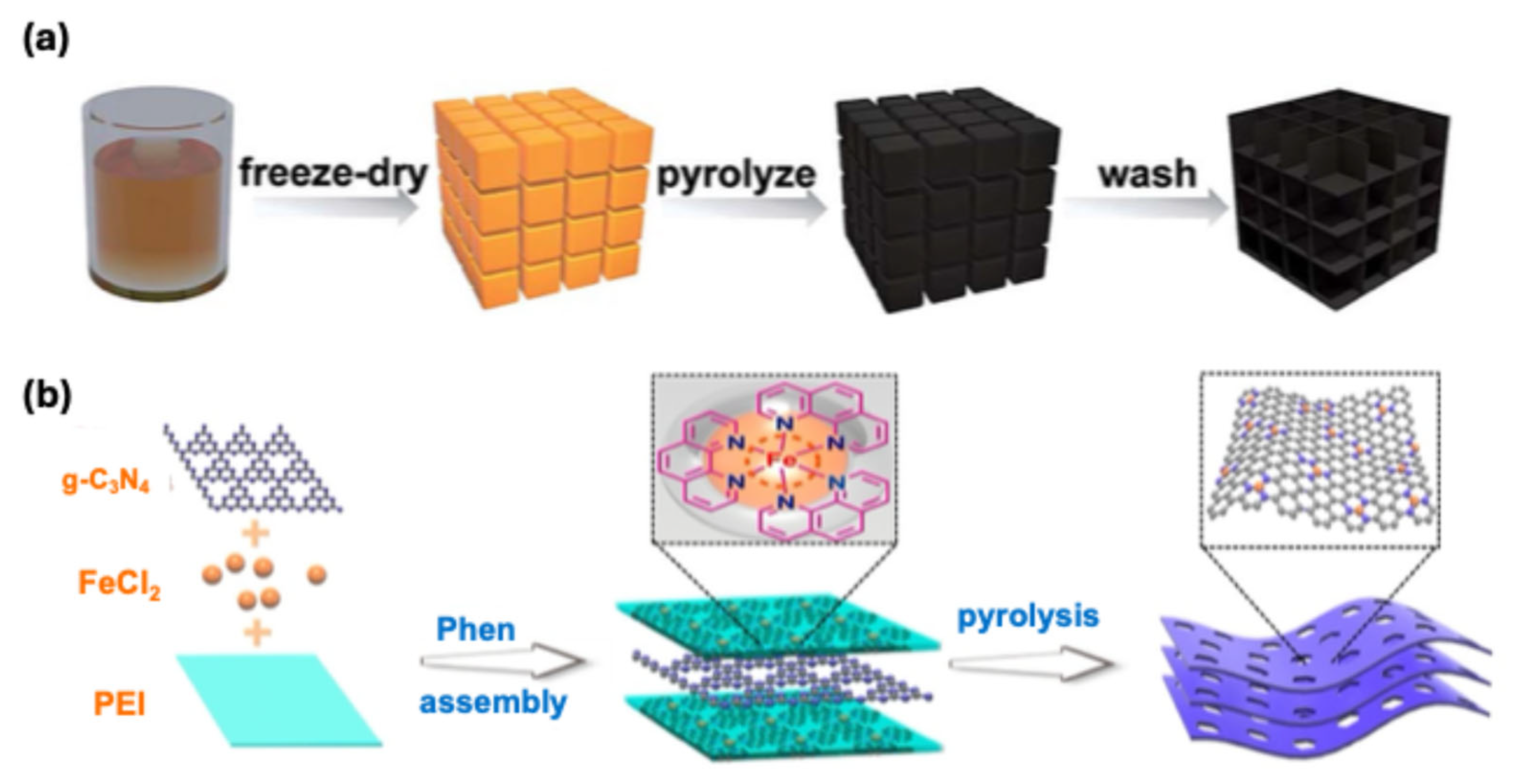
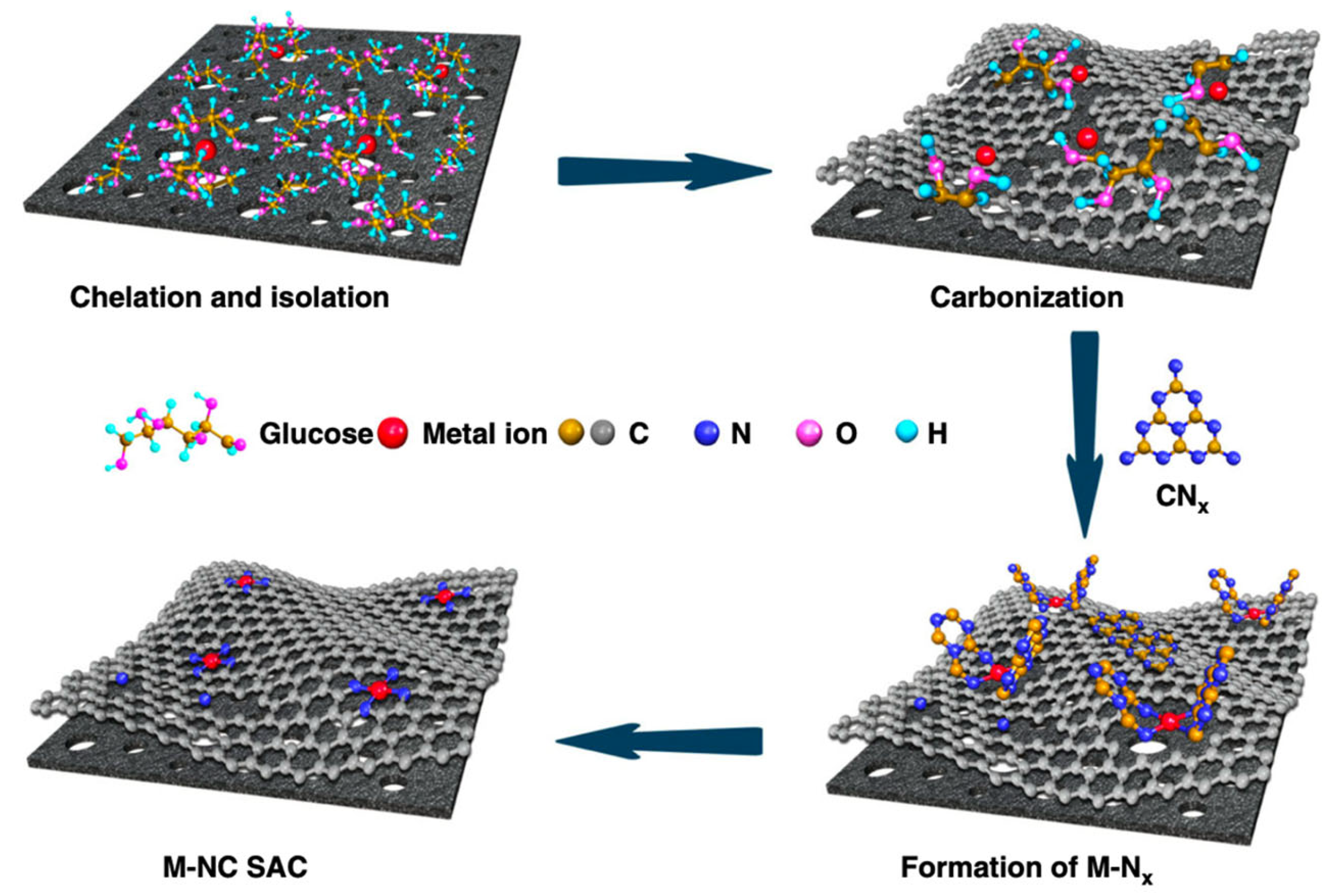
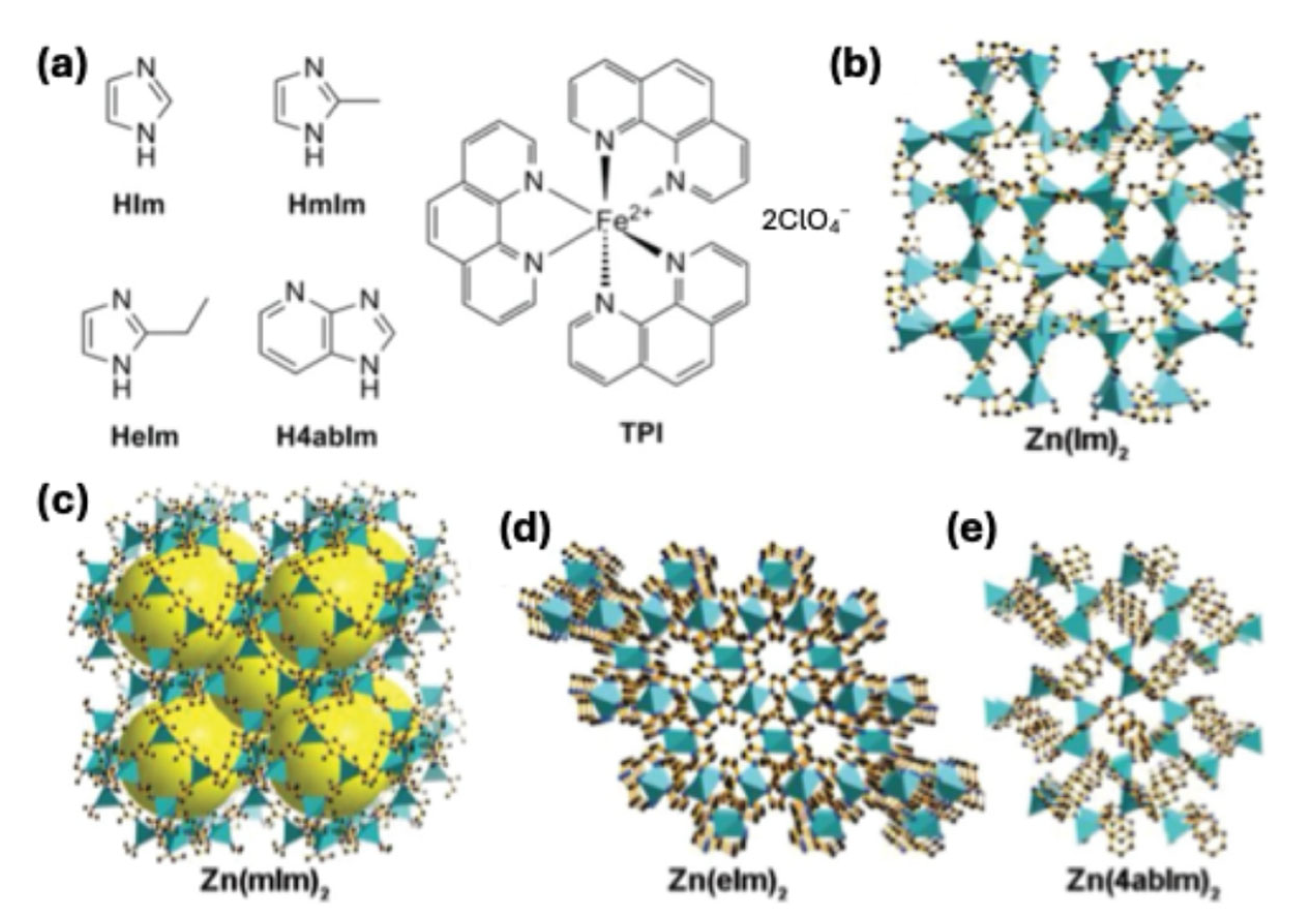
3.1. Iron–Nitrogen–Carbon (Fe-N-C) Catalysts

Among the transition metal–nitrogen–carbon catalysts, Fe-N-C catalysts have been shown to be the most promising for the oxygen reduction reaction due to their high activity and economic value [34]. Various synthesis methods of Fe-N-C composites can differ in metal loadings and active site densities. Some promising synthesis approaches include pyrolysis, Fe-doped MOF precursors, wet impregnation, ball-milling, cascade anchoring strategies, co-doping, and others. Fe-N-C synthesis strategies each offer trade-offs in activity, stability, and scalability. Pyrolysis is essential for Fe-Nx site formation, though it can also lead to the generation of inactive Fe species. In MOF-derived approaches, the MOF acts as a template that, upon pyrolysis, yields materials with high surface area and atomic dispersion; however, these methods can be complex and often result in low yields. Wet impregnation is scalable but may suffer from poor site uniformity. Emerging methods like cascade anchoring improve site accessibility but involve multi-step synthesis. Understanding these trade-offs is essential for the rational design of future Fe-N-C catalysts, particularly as the field moves toward optimizing site density, durability, and integration into practical MEA architectures.
Pyrolysis: Pyrolysis is one of the most common approaches for synthesizing Fe-N-C composites. This was employed by Ao et al., as shown in Figure 2a, where they first freeze-dried sodium chloride, dicyandiamide, D(+)-glucosamine hydrochloride, and anhydrous iron (III) chloride in a vacuum before heating to 550 °C for 3 h and annealing at 800 °C for another 2 h in an inert argon gas environment. Ao et al.’s synthesis yielded a Fe/N-functionalized 3D porous carbon network, and ultrafine Fe4N nanoparticles were grown in the carbon framework during pyrolysis [35]. Another pyrolysis approach in which single Fe sites on N-doped porous carbon nanosheets were synthesized using a confined pyrolysis strategy was employed by Z. Yang et al., as shown in Figure 2b [36]. By utilizing a poly(ether imide) polymer as a carbon precursor and 1,10-phenanthroline (Phen) as a space isolation agent, they were able to promote the full Fe transformation to single Fe atoms without forming Fe nanoparticles. Specifically, cyanuric acid and melamine dispersed in ethanol were filtered and then pyrolyzed at 550 °C for 6 h to form C3N4 nanosheets, which were then freeze-dried and heated to 100 °C for 1 h with ferrous chloride, the poly(ether imide) polymer, and Phen to synthesize the final catalyst [36].
While these two examples are discussed in detail, pyrolysis is also widely used in other synthesis strategies, including MOF-derived and support-assisted methods. MOF-derived catalysts, for instance, utilize metal–organic frameworks, like ZIF-8, as precursors, as mentioned in a separate section [37]. Upon pyrolysis, these frameworks decompose to form nitrogen-doped carbon matrices embedded with atomically dispersed Fe-N4 sites [38,39]. This method benefits from the uniform distribution of metal centers and the inherent porosity of MOFs, which can enhance mass transport and active site accessibility [40]. Support-assisted strategies, on the other hand, involve impregnating nitrogen-rich carbon supports—such as carbon nanotubes or graphene—with iron precursors, followed by pyrolysis [41,42]. This approach allows for better control over the morphology and electronic properties of the resulting catalysts, as the characteristics of the support material can influence the dispersion and coordination environment of the active Fe sites [43]. Highlighting the distinctions between these pyrolysis-based methods—such as MOF-derived, support-assisted, and polymer-confined strategies—helps illustrate the wide range of structural control and active site engineering possible in Fe-N-C catalyst synthesis.
Cascade Anchoring Strategy: Traditional pyrolysis synthesis offers relatively low metal loadings (<5 at.%). To combat this low metal loading, strategies, such as cascade anchoring, can be employed to increase metal loading up to 12.1 wt.%. This was achieved by L. Zhao et al., who were able to produce a scalable synthesis with high metal-Nx loading. As shown in Figure 3, the metal ions are first chelated using glucose as a chelating agent before being anchored onto high-surface-area, oxygen-species-rich porous carbon supports and pyrolyzed at ~500 °C to allow for maximized protection of the metal ions. From their synthesis, they were able to determine that the chelation of metal ions, physical isolation of the chelate complex, and N-species binding at increased temperatures were key factors in achieving high-metal-loading single-atom catalysts (SACs) [44].
Metal–Organic Frameworks: Hybrid crystalline materials, such as metal–organic frameworks (MOFs), have become some common precursors for metal–nitrogen–carbon complexes. Zeolitic imidazolate frameworks (ZIFs), which are a subclass of MOFs, contain N-filled ligands and tetrahedral coordination metal ions and are a type of coordination polymer. As shown in Figure 4, these ZIFs can be used as sacrificial templates to prepare nitrogen-doped carbon materials due to their nitrogen-rich composition. As employed by D. Zhao et al., metalated ZIFs were synthesized by heating ZnO, N-containing ligands, and tris-1,10-phenanthroline iron(II) perchlorate (TPI) (as seen in Figure 4a) [37]. After pyrolization at 1050 °C, acid washing, and a second 950 °C heat treatment, a final catalyst with a uniformly dispersed iron complex can be formed. Even though there is a lack of porosity in some of the precursors, the pyrolyzed ZIF catalysts are still able to have great surface areas. Ahluwalia et al. took a similar approach using a similar Fe-ZIF precursor and pyrolyzing at 1100 °C [45]. Their synthesis yielded a stable Fe-N-C catalyst with atomically dispersed Fe sites.
As shown in Figure 5, another technique involving ZIFs and MOFs includes ball-milling. Zhan et al. used this approach to create bamboo-like carbon nanotubes (BLCNTs) with dispersed Fe-centered active sites (nitrogen-coordinated). Ball-milling NH2-MIL-88B (iron source) and ZIF-8 (carbon source) precursors together destroys their crystal structure and uniformly mixes them. Zhan et al. controlled the proportion of precursors and utilized pyrolysis to control the morphology of the bamboo-like carbon nanotubes [46].
While MOFs, such as ZIFs, serve as sacrificial templates, they differ from traditional templates like silica. In silica-based templating, the silica is removed after pyrolysis, usually by acid etching, to generate porosity in the final material [47,48]. For example, Gianola et al. [47] highlighted how different silica removal methods, including acid-free approaches developed by Atanassov’s group, influence catalyst porosity and performance. MOFs, on the other hand, are not removed but instead undergo a transformation during thermal treatment, forming part of the carbon-based framework and contributing directly to the structure and functionality of the resulting catalyst [49].
Secondary Metals Present in Fe-N-C: To change/tune the electronic properties of Fe-N-C catalysts, secondary metals or molecules are introduced into the carbon matrix. G. Yang et al. explored atomically dispersed Mn-N in Fe-N-C [50], and Jin et al. explored porous rod-like Bi-O structures [51]. A quick overview of their synthesis methods is shown in Figure 6 and Figure 7. These will not be discussed in depth as they are similar to the synthesis methods discussed in the pyrolysis and metal–organic framework sections, with the addition of Mn and Bi precursors. In the case of Mn-N incorporation, Yang et al. reported that Mn atoms modulate the electronic environment around the Fe-N4 active sites, resulting in a downshift of the d-band center of Fe. This downshift is described as electron delocalization from the Fe3+ centers, shifting their spin state from low spin (t2g5 eg0) to intermediate spin (t2g4 eg1), which enhances the overlap between Fe 3d orbitals and the π antibonding orbitals of O2. Electronic tuning weakens the binding strength of oxygen intermediates, enhancing the overall ORR kinetics and improving catalytic activity and durability [50]. This type of electronic modulation is not unique to Mn; other secondary metals and Fe-N-C systems have also been shown to influence the spin state and d-band center of Fe, offering a versatile strategy to optimize catalytic performance [52].

3.2. Molecular Catalysts on Carbon Supports

Materials such as carbon matrices, carbon nanotubes, and graphene have also been studied independently for their application as cathode catalysts. Pristine graphene is considered a semiconductor with no bandgap due to its sp2-bonded carbon atoms, which limits application in energy storage and catalysis [53,54,55]. Through covalent bonding with graphene, atoms such as fluorine (F), nitrogen (N), and boron (B) can be substitutionally doped into graphene to disrupt the sp2 network and cause sp3-defect regions [27]. This allows for the tuning of electronic properties and modification of surface chemistry. Fe-N-C complexes and macrocyclic compounds can be combined with carbon matrices, carbon nanotubes, and graphene to increase ORR activity and overall stability. Combining these materials in their pristine and modified (doped/exchanged) varieties has proven to be beneficial and favorable towards ORR activity and stability. Incorporating Fe-based macrocycles, like FePc, into conductive supports, such as graphene or CNTs, improves site dispersion and electron conductivity, leading to increases in onset potential by up to ~50 mV and 2–3× higher limiting current densities compared to unsupported counterparts [28,56,57,58]. In some cases, onset and half-wave potentials approach those of commercial Pt/C catalysts (e.g., ~0.92 V vs. RHE) [28], with enhanced stability, where over 90% of the initial activity is retained after 10,000 cycles in acidic media [59,60,61]. This approach also enables fine-tuning of the Fe coordination environment through ligand exchange or heteroatom doping of the carbon host, further enhancing ORR kinetics and promoting the desirable four-electron reduction pathway. First, doping of graphene and carbon nanotubes will be discussed before moving on to phthalocyanines and porphyrins that are commonly supported by these carbon-based structures as they prevent aggregation and can supply supplementary electron sites [28].
Doping of Graphene and Carbon Nanotubes: Dopants play a large part in the catalytic activity and electronic properties of carbon-based materials. Atomic-scale substitution can redistribute local strain within a catalyst particle, altering the energetic stability of surface configurations and potentially exposing more catalytically active sites. As shown by Husic et al., even a single dopant atom can trigger solid–solid transitions or shift structural preferences, leading to surface reconstructions that affect site accessibility and stability [62]. As mentioned in a previous section, sp3-defect regions can be generated in the sp2 network of graphene by introducing substitutional dopants, such as nitrogen (N) and boron (B). Though other atoms such as phosphorus (P) and sulfur (S) can also be doped into the graphene matrix, they are not as similar in size to carbon as N and B atoms and would disrupt the matrix to a much higher degree and deform the planar nature of graphene [27]. With relatively low doping percentages of <3 at.%, the electronic, magnetic, and optical properties in graphene can be greatly influenced due to the polarization that is created by the differences in electronegativity. Nitrogen and boron are common graphene dopants due to their similarity in size and electronegativity to carbon and have been studied intensively for various applications. Nitrogen-doped graphene has been successfully synthesized using thermal annealing, chemical vapor deposition (CVD), solvothermal synthesis, supercritical reaction, arc discharge, plasma, nitrogen bombardment, and ball-milling processes at doping concentrations between 0.6 and 16 at.% [27,52,63,64,65].
As shown in Figure 8a, nitrogen-doped graphene is made of various types of nitrogen in the graphene matrix, including pyridinic (sp2-hybridized at edge sites), pyrrolic (sp3- hybridized), and graphitic (sp2-hybridized in the graphene matrix). Sun et al. mention that pyridinic and pyrrolic N allow for improved pseudo-capacitance and that graphitic N enhances conductivity (favoring electron transport during the charge/discharge process) [66]. The most common precursors for nitrogen-doped graphene include graphene or graphene oxide and a nitrogen-containing molecule such as NH3. Boron-doped graphene for the application of ORR is slightly less common but does have a more energetically favorable formation energy of ~5.6 eV/atom (compared to 8.0 eV/atom for nitrogen-doping) [67]. Boron-doped graphene has been successfully synthesized using chemical vapor deposition (CVD), thermal annealing, thermal exfoliation, liquid process, arc discharge, and microwave plasma, and the Wurtz-type reductive coupling reaction processes dopant concentrations between 0.5 and 13.85 at.%. As shown in Figure 8b, two types of stable boron doping are possible in the boron-doped graphene. These include in-plane doping of boron (graphitic), which is sp2-hybridized, and the formation of a “boron silane”, which is where B atoms are located in a π-conjugated system [68]. Borane silane atoms have only been present in one synthesis method (CVD). The most common precursors for boron-doped graphene include graphene oxide and a boron-containing molecule, such as boron powder, BH3-tetrahydrofuran (BH3-THF), boron tribromide (BBr3), and diborane (B2H6). The many available synthesis techniques make both N- and B-doped graphene a great candidate for the commercialization of fuel cells.
As shown in Figure 9, there are different types of carbon nanotube supports: single-walled, double-walled, and multi-walled nanotubes. The different types of carbon nanotubes behave differently from one another and provide support to other complexes deposited onto them. Most researchers purchase double- and multi-walled nanotubes and use them as received without any further purification step. However, in oxidative treatments, they can be subjected to 35% HNO3 under reflux and heating conditions (100 °C) for 12 h. Single-walled carbon nanotubes can be produced using a laser ablation technique and can be purified to remove any amorphous carbon particles, which results in superficial oxidation [71].
Iron Phthalocyanine on Carbon Nanotubes: As shown previously in Figure 9, carbon nanotubes can either be single-walled, double-walled, or multi-walled. However, catalyst preparation tends to be the same no matter the type of carbon nanotube (CNT). Morozan et al. were able to synthesize their catalysts by ultrasonicating a 1:2 w/w ratio of iron phthalocyanine, which was dissolved in THF and CNT powder, and then, the THF was evaporated off. Their proposed chemical representation of a hybrid catalyst for another phthalocyanine they studied is shown in Figure 10a [73]. Govan et al. took a slightly different approach by introducing eight cyano-ligand groups into their phthalocyanine, as shown in Figure 10b, in an attempt to tune their catalyst [74]. Their synthesis also included a physical deposition with sonication to ensure homogeneous dispersion in solution.
Iron Phthalocyanine on Reduced Graphene: Jiang et al. were able to synthesize iron phthalocyanine supported on chemically reduced graphene by first synthesizing graphene sheets through the partial reduction of graphene oxide, following the modified Hummers’ method. Then, by having both iron phthalocyanine and graphene dispersed in N,N-dimethylformamide (DMF), they were able to incorporate iron phthalocyanine into the graphene by stirring for 6 h and sonicating [28]. This catalyst and doped-graphene variants were explored computationally by Helsel et al. and can be seen in Figure 11 [75,76,77].
Iron Polyporphyrin: Polyporphyrins can offer a high density of iron macrocyclic centers that are nitrogen-coordinated. Achieved successfully by Yuan et al., the overall synthesis and polymerization are displayed in Figure 12. After these steps were taken to synthesize the catalyst (PFeTTPP), it was thermally activated by being pyrolyzed from 600 to 1000 °C [29]. The simulated stacking of their catalyst is shown in Figure 12b.

4. Performance Evaluation of Non-PGM Catalysts

To be able to experimentally characterize a catalyst for fuel cell applications, electrochemical measurements and/or fuel cell tests must be conducted. Papers that involve purely computational work use a parameter called overpotential to quantify their catalyst’s ORR activity. Research that involves mainly experimental work mostly utilizes a potentiostat, electrode rotator, and 3/4-electrode electrochemical cell to quantify parameters such as onset and half-wave potentials. If equipped with an available fuel cell, some researchers utilize actual fuel cell tests to obtain a better picture of the stability and practicality in actual applications.

4.1. Electrochemical Characterization Techniques

Electrochemical testing for fuel cell catalysts typically employs a three-electrode configuration using a rotating disk electrode (RDE) or rotating ring–disk electrode (RRDE), with the working electrode used to evaluate the catalyst. The working electrode is often glassy carbon, while RRDE setups include a surrounding ring, commonly platinum. However, for platinum-group metal-free (PGM-free) catalyst studies, platinum should be avoided as a counter electrode due to the risk of contamination through Pt dissolution and redeposition. Instead, graphite rods are preferred because they are chemically inert under typical electrochemical conditions, minimizing the risk of introducing unwanted species that might affect the catalyst’s performance [78]. A reference electrode provides a stable potential (e.g., Ag/AgCl or saturated calomel), and reported values are commonly converted to the reversible hydrogen electrode (RHE) scale for consistency [79]. The three/four electrodes are arranged and then submerged in an acidic (<7 pH) O2-saturated electrolyte solution, which is typically 0.1 M HClO4 for Fe-N-C catalysts. Fe-N-C catalysts are susceptible to poisoning by hydrochloric acid (HCl) as chloride ions strongly adsorb onto the Fe-Nx active sites, blocking oxygen access and significantly reducing ORR activity [80]. The studied mechanism, ORR, involves reducing oxygen. An O2-saturated electrolyte solution allows for the reaction to occur without much resistance when certain voltages are applied.
Cyclic voltammetry (CV) is one of the most common electrochemical techniques in studying the reduction and oxidation processes of a particular electrode, catalyst, or species. In essence, cyclic voltammetry is where a range of potentials is swept in forward and reverse directions. CV reveals the cathodic peak potential and the half-wave potential, which can be calculated by taking the middle point between the cathodic and anodic peaks [81]. Linear sweep voltammetry (LSV) is another common electrochemical technique used where the potentials have a single forward sweep. Taking the intersection of two tangents on the non-faradaic zone and faradic zone in an LSV allows for the determination of the onset potential (Eonset) [82]. In order to study the kinetics and mechanisms involved in a glass carbon electrode, a method such as Koutecky–Levich analysis must be used. The analysis includes running multiple LSV sweeps at different rotation rates. This analysis reveals the number of electrons (n) involved in the reaction mechanism, or which ORR pathway the deposited catalyst takes [83]. Another key metric used to understand the activity of a catalyst is the Tafel slope. Tafel slopes help elucidate the kinetics of a catalyst by aiding the determination of the rate-limiting step, understanding its mass transport limitations, and the efficiency of the catalyst [84]. Due to the nature of this review, Tafel slopes will not be discussed, and reaction mechanisms can be deduced via the total number of electrons transferred from the Koutecky–Levich analysis. Half-wave potential alone does not provide a complete picture of ORR performance. Catalyst loading and mass activity (e.g., A mg−1 catalyst or A mg−1 Fe) are also critical metrics, especially when comparing selectivity and minimizing the effect of artifacts, such as peroxide re-reduction in high-loading films. Therefore, where possible, mass activity and loading information are highlighted in this review to provide more accurate benchmarking.
When utilizing a full membrane electrode assembly (MEA) with a prepared catalyst, the peak power density, along with the volumetric and gravimetric current densities, are considered key performance metrics. These values can be measured from the current-voltage polarization curves and power density tests. The values determined from the fuel cell test are more realistic than purely the electrochemical measurements; however, the cost, complexity, and time associated with operating a fuel cell, even in a lab setting, are more expensive than the general electrochemical cell setup used for preliminary catalyst screening [85].
Generally, to test the stability and durability of the studied catalyst on a lab scale, chronoamperometry is used over the course of a few hours to a few days by holding the electrode at a typical working potential for fuel cell operation, and then, current retention is measured over this time frame. It is generally directly compared to a control commercial Pt/C catalyst and can yield promising information regarding a catalyst’s stability [34].

4.2. Comparison of ORR Activity

Table 1 shows a table of the catalysts discussed in the previous synthesis method section, along with a few key additions that were not discussed. The catalyst loadings are either reported directly from the reference or were estimated from the given drop-casted catalyst ink weights/volumes and estimated working electrode areas (denoted by ^ in Table 1). In the case of Fe-N-C-10/1-950 (BLCNTs) [46], the drop-casted volume was not specified; therefore, the loading could not be calculated from the given data.
It is important to note that while the focus of this review is on Fe-N-C catalysts for PEMFC cathodes operating in acidic media, studies conducted on alkaline electrolytes, such as KOH, have contributed significantly to the understanding of ORR mechanisms and the development of active site structures. Therefore, select examples from alkaline studies are included for comparison and insight. Mass activity (im, A mg−1) should be interpreted alongside catalyst loading (mg cm−2) as both directly influence observed current density and selectivity, especially in systems like Fe-N-C, where thick films may mask peroxide production through re-reduction. However, mass activity values were not included in the comparison table, as they were not consistently reported across the reviewed studies and could not be reliably calculated in the absence of complete loading and kinetic current data.
Regardless of the preparation method, Table 1 shows that the main dominating pathway for Fe-N-C catalysts is the direct four-electron pathway, as most electron transfer numbers are around four, and there is minimal hydrogen peroxide (H2O2) formation in the catalysts, for which electron transfer numbers were not calculated. With 13.4% H2O2 formation, NGr (nitrogen-doped graphene) by itself seems to have a lower electron transfer number than other graphene. This could be due to nitrogen having one more valence electron than the carbon atoms in the graphene. Looking at carbon networks or materials that have iron and nitrogen built into them in a single catalyst, these materials have very promising half-wave and onset potentials. A high onset potential is indicative of a low overpotential required for actual fuel cell operation. In catalysts, such as Z. Yang et al.’s Fe SAs/N-C, where 3.5 wt.% single-iron-atom active sites are dispersed in a porous nitrogen-doped carbon matrix, the onset and half-wave potentials are exceptionally favorable, with the onset potential being over 1 V vs. RHE in alkaline media [36]. This could potentially mean that the space isolation agent they used to create the single-iron-atom active sites (3.5 wt.%) within the carbon network has a larger effect than the increased metal loading found by the cascade anchoring strategy employed by L. Zhao et al. [44]. H. Jin et al. and Z. Yang et al. both modified their Fe-N-C catalysts with a secondary metal (Mn and Bi) to increase ORR activity [36,51]. Though the addition of the secondary metal improved the performance of both catalysts, neither catalyst performed better than the previously mentioned Fe SAs/N-C. There should be further studies conducted to investigate whether manganese or bismuth could be incorporated into the Fe SAs/N-C matrix to improve overpotential. Iron phthalocyanine on reduced graphene, studied by Y. Jiang et al., performed very well, even better than porous polyporphyrin with a high surface area [29]. Iron phthalocyanine is supported by Van der Waals dispersion forces, and it is known that the combination of iron phthalocyanine, supported by the reduced graphene substrate, allows for extra supplementary electron sites to be formed. Additionally, π- π interactions aid in preventing the aggregation of iron phthalocyanine, which aids in conductivity [28]. Experimental research should be conducted to tune the graphene substrate, like substrate doping (with N and B atoms), as mentioned previously, to potentially increase the overall ORR activity of the catalyst. The carbon nanotube (CNT) catalysts discussed in this review either have iron phthalocyanine physically adsorbed on the CNTs through Van der Waals dispersion forces or iron highly dispersed throughout the CNTs. A. Morozan et al. discussed the use of iron phthalocyanine deposited on single-, double-, and multi-walled carbon nanotubes, in which the acid-treated multi-walled CNTs displayed the best performance [73]. When looking at Govan et al.’s similar experiment with iron phthalocyanine that has eight hydrogens substituted with cyano groups deposited on single-walled CNTs, this material offers a higher onset potential than even iron phthalocyanine on multi-walled CNTs (the single-walled CNTs performed worse) [74]. This increase in ORR activity could potentially mean that the extra cyano groups on the ends of the phthalocyanine are aiding the charge transfer to make the reaction easier to complete. Overall, it seems that catalysts that had single iron atoms or Fe-N4 -coordinated molecules performed better than just uniformly dispersing Fe in a carbon network, even at much higher loading percentages.
Although Fe-N-C catalysts often exhibit excellent ORR activity in alkaline media, their performance typically declines under acidic conditions due to harsher operating environments and proton-rich electrolytes, which lead to lower onset and half-wave potentials. Protonation of pyridinic-N species and carbon support corrosion are the main factors in this activity decline [87]. In acidic media, the commercial Pt/C catalyst has an approximate onset potential of 0.9 V and a half-wave potential of 0.8–0.85 V vs. SHE [88]. Though no Fe-N-C catalyst has yet surpassed Pt/C in terms of activity and stability due to the harsh operating conditions of PEMFCs, the gap in performance for this class of catalysts has narrowed significantly in the last few years. The facile synthesis methods described in this review have enabled greater active site dispersion and the modulation of electronic properties through nitrogen coordination and secondary metal co-doping, thereby enhancing the structural and catalytic performance of Fe-N-C catalysts.
While most Fe-N-C studies focus on half-cell measurements, such as RDE or RRDE, to evaluate intrinsic ORR activity, a smaller number extend testing to full MEA fuel cell configurations. As summarized in Table 2, studies on catalysts, such as PFeTTPP-700, Zn(mlm)2TPIP, Zn(elm)2TPIP, Fe SAs/N-C, and Fe-N-C-10/1-950, report polarization curves and peak power densities under H2-O2 conditions, with loadings ranging from 1.5 to 4.0 mgcat cm−2. These studies also report or enable the estimation of volumetric current densities as a more device-relevant metric that normalizes currents by both geometric area and catalyst layer thickness. For instance, the Fe-N-C-10/1-950 catalyst achieves an estimated volumetric current density of ~0.85 A cm−3 at 0.7 V and a peak power density of 770 mW cm−2 at approximately 0.48 V. While some values are directly reported and others are estimated from polarization plots, this comparison highlights that several Fe-N-C catalysts now approach the performance range of commercial Pt-based systems, particularly when evaluated by space-constrained metrics relevant to practical device integration. For context, leading commercial catalysts, such as Pt/C and Pt-Co/C, have achieved peak power densities of up to 0.84 W cm−2 at 0.67 V (LANL, using 0.1 mgPt cm−2 loading under H2/air, 80 °C, 100% RH, 150 kPa) and 0.94–1.0 W cm−2 with Pt-Co alloy catalysts under similar conditions, as reported by General Motors and other groups. These values reflect the current benchmarks for DOE target-aligned PEMFC performance using precious-metal-based electrodes [89]. While Fe-N-C catalysts still fall short of these absolute performance levels, the gap has narrowed significantly, particularly in terms of volumetric current density and power output per unit loading. These results suggest that with continued improvements in site accessibility, conductivity, and catalyst layer architecture, non-precious metal catalysts are becoming increasingly viable for practical PEMFC applications.

4.3. Future Perspectives and Challenges

Recent advances in Fe-N-C catalysts for hydrogen fuel cells have led to significant progress in multiple areas. These include high oxygen reduction reaction (ORR) activity approaching that of Pt/C (E1/2 = ~0.8 V), high power density in MEAs (e.g., >0.7 A cm−2 at 0.7 V), and site densities exceeding 1019 sites gram−1 [90]. The development of atomically dispersed Fe-Nx active sites and the use of 2D or porous supports, such as g-FePc and BLCNTs, have further improved active site utilization [28,46]. Additionally, volumetric current density has emerged as an increasingly relevant performance metric, reflecting improvements in catalyst layer architecture and practical device integration.
Despite these achievements, several critical challenges remain. The key issues include limited long-term stability under fuel cell operating conditions, acid leaching of Fe sites, and lower performance under H2/air compared to H2/O2 conditions. The ability to accurately characterize which Fe-Nx sites are electrochemically active and how accessible they are in a working electrode remains a major limitation to rational catalyst design. Trade-offs also persist between maximizing site density and ensuring sufficient mass transport, particularly in thicker catalyst layers. In addition, kinetic limitations in O-O bond cleavage and the initial electron transfer step in the ORR continue to hinder performance relative to Pt-based benchmarks. Among these, stability remains the most significant barrier to practical deployment. While a few recent studies, such as Fe-N-C-10/1-950 retaining 70% of its current density after 24 h in an MEA, have shown encouraging durability, most Fe-N-C catalysts still undergo substantial degradation over time [46]. The causes are multifaceted: acid-induced demetalation of Fe-Nx sites, carbon corrosion at high potentials, and mechanical or chemical collapse of the porous structure during prolonged operation. The harsh acidic environment and voltage cycling during fuel cell start-up/shutdown further accelerate these degradation pathways. Moreover, Fe-Nx sites may leach or transform into inactive species, especially in the presence of H2O2 intermediates.
Efforts to address these issues, such as stronger Fe anchoring, sacrificial scavengers for reactive oxygen species, and graphitized supports, have shown partial success, but durability still lags far behind that of commercial Pt/C. Moving forward, research should place greater emphasis on in situ diagnostics to track catalyst evolution under working conditions and standardized durability testing protocols that enable fair comparison across studies. Ultimately, achieving a commercially viable performance will require integrated advances in both materials design and electrode engineering, including attention to ionomer distribution, water management, and catalyst layer morphology. An overview of the key challenges and progress made in Fe-N-C catalysts can be found in Figure 13.

5. Conclusions

Fe-N-C catalysts have emerged as the most promising non-precious alternatives to Pt/C for the oxygen reduction reaction in proton exchange membrane fuel cells. While still inferior to the commercial Pt/C and Pt-Co/C catalysts, recent advances in synthesis strategies have allowed for significant activity improvements in the durability and activity of Fe-N-C catalysts in acidic conditions. Pyrolysis, metal–organic framework (MOF)-derived structures, wet impregnation, and cascade anchoring have enabled improved site dispersion, enhanced nitrogen coordination, and the fine-tuning of electronic properties through heteroatom co-doping. Allowing for the increase in active site density and overall catalyst stability, Fe-N-C catalysts are now closer to practical use in fuel cells. Long-term stability and scalable production of these catalysts remain a key challenge in non-PGM fuel cell research. Continued investigation into the relationship between catalyst structure, electronic properties, and performance is necessary to fully bridge the gap to commercial viability. Achieving commercially viable stability will require coordinated progress in both molecular design and electrode-level engineering. Strategies such as graphitized supports, stronger Fe-N bonding, and protective architectures show promise but remain insufficient under realistic MEA operating conditions. Future work should prioritize operando diagnostics and standardized durability protocols to better understand degradation pathways and guide rational improvements.

Funding

This research was funded by U.S. Department of Energy, Office of Science, Office of Basic Energy Sciences, with grant number DE-SC0024595. Additionally, thanks to the New Mexico Space Grant Consortium (NMSGC) and the State Legislative Fund, New Mexico, for financial support.

Data Availability Statement

No new data were created or analyzed in this study. Data sharing is not applicable to this article.

Conflicts of Interest

The authors declare no competing financial interests.

References

  1. Alternative Fuels Data Center: Vehicle Registration Counts by State. 2022. Available online: https://afdc.energy.gov (accessed on 7 June 2025).
  2. EIA (U.S. Energy Information Administration). Gasoline Explained. 2016. Available online: https://www.eia.gov/energyexplained/gasoline/ (accessed on 7 June 2025).
  3. United States Environmental Protection Agency. Greenhouse Gas Emissions from a Typical Passenger Vehicle; US EPA: Washington, DC, USA, 2022.
  4. NASA. What Is the Greenhouse Effect? In Global Climate Change: Vital Signs of the Planet; NASA: Washington, DC, USA, 2019. [Google Scholar]
  5. The Causes of Climate Change. In Climate Change: Vital Signs of the Planet; NASA: Washington, DC, USA, 2019.
  6. Kuo, G. When Fossil Fuels Run Out, What Then? MAHB: Stanford, CA, USA, 2019. [Google Scholar]
  7. Lindsey, R. Climate Change: Atmospheric Carbon Dioxide. 2023. Available online: https://Climate.gov (accessed on 7 June 2025).
  8. Dulău, L.-I. CO2 Emissions of Battery Electric Vehicles and Hydrogen Fuel Cell Vehicles. Clean Technol. 2023, 5, 696–712. [Google Scholar] [CrossRef]
  9. Kim, J.W.; Boo, K.J.; Cho, J.H.; Moon, I. 1-Key challenges in the development of an infrastructure for hydrogen production, delivery, storage and use. In Advances in Hydrogen Production, Storage and Distribution; Basile, A., Iulianelli, A., Eds.; Woodhead Publishing: Sawston, UK, 2014; pp. 3–31. [Google Scholar]
  10. Thompson, S.T.; James, B.D.; Huya-Kouadio, J.M.; Houchins, C.; DeSantis, D.A.; Ahluwalia, R.; Wilson, A.R.; Kleen, G.; Papageorgopoulos, D. Direct hydrogen fuel cell electric vehicle cost analysis: System and high-volume manufacturing description, validation, and outlook. J. Power Sources 2018, 399, 304–313. [Google Scholar] [CrossRef]
  11. Wang, C.; Spendelow, J.S. Recent developments in Pt–Co catalysts for proton-exchange membrane fuel cells. Curr. Opin. Electrochem. 2021, 28, 100715. [Google Scholar] [CrossRef]
  12. Yarlagadda, V.; Carpenter, M.K.; Moylan, T.E.; Kukreja, R.S.; Koestner, R.; Gu, W.; Thompson, L.; Kongkanand, A. Boosting Fuel Cell Performance with Accessible Carbon Mesopores. ACS Energy Lett. 2018, 3, 618–621. [Google Scholar] [CrossRef]
  13. Müller-Hülstede, J.; Uhlig, L.M.; Schmies, H.; Schonvogel, D.; Meyer, Q.; Nie, Y.; Zhao, C.; Vidakovic, J.; Wagner, P. Towards the Reduction of Pt Loading in High Temperature Proton Exchange Membrane Fuel Cells—Effect of Fe−N−C in Pt-Alloy Cathodes. ChemSusChem 2023, 16, e202202046. [Google Scholar] [CrossRef]
  14. Chen, L.; Wan, X.; Zhao, X.; Li, W.; Liu, X.; Zheng, L.; Liu, Q.; Yu, R.; Shui, J. Spatial porosity design of Fe-N-C catalysts for high power density PEM fuel cells and detection of water saturation of the catalyst layer by a microwave method. J. Mater. Chem. A 2022, 10, 7764–7772. [Google Scholar] [CrossRef]
  15. Asset, T.; Atanassov, P. Iron-Nitrogen-Carbon Catalysts for Proton Exchange Membrane Fuel Cells. Joule 2020, 4, 33–44. [Google Scholar] [CrossRef]
  16. Birry, L.; Zagal, J.H.; Dodelet, J.-P. Does CO poison Fe-based catalysts for ORR? Electrochem. Commun. 2010, 12, 628–631. [Google Scholar] [CrossRef]
  17. Kumar, A.; Zhang, Y.; Liu, W.; Sun, X. The chemistry, recent advancements and activity descriptors for macrocycles based electrocatalysts in oxygen reduction reaction. Coord. Chem. Rev. 2020, 402, 213047. [Google Scholar] [CrossRef]
  18. Winter, M.; Brodd, R.J. What Are Batteries, Fuel Cells, and Supercapacitors? Chem. Rev. 2004, 104, 4245–4270. [Google Scholar] [CrossRef]
  19. Wang, X.X.; Swihart, M.T.; Wu, G. Achievements, challenges and perspectives on cathode catalysts in proton exchange membrane fuel cells for transportation. Nat. Catal. 2019, 2, 578–589. [Google Scholar] [CrossRef]
  20. Rabis, A.; Rodriguez, P.; Schmidt, T.J. Electrocatalysis for Polymer Electrolyte Fuel Cells: Recent Achievements and Future Challenges. ACS Catal. 2012, 2, 864–890. [Google Scholar] [CrossRef]
  21. Vaca, S. Toyota Introduces Second-Generation Mirai Fuel Cell Electric Vehicle as Design and Technology Flagship Sedan; Toyota USA Newsroom: Plano, TX, USA, 2020. [Google Scholar]
  22. Bezerra, C.W.B.; Zhang, L.; Lee, K.; Liu, H.; Marques, A.L.B.; Marques, E.P.; Wang, H.; Zhang, J. A review of Fe-N/C and Co–N/C catalysts for the oxygen reduction reaction. Electrochim. Acta 2008, 53, 4937–4951. [Google Scholar] [CrossRef]
  23. Proietti, E.; Jaouen, F.; Lefèvre, M.; Larouche, N.; Tian, J.; Herranz, J.; Dodelet, J.-P. Iron-based cathode catalyst with enhanced power density in polymer electrolyte membrane fuel cells. Nat. Commun. 2011, 2, 416. [Google Scholar] [CrossRef]
  24. Wang, X.; Li, Z.; Qu, Y.; Yuan, T.; Wang, W.; Wu, Y.; Li, Y. Review of Metal Catalysts for Oxygen Reduction Reaction: From Nanoscale Engineering to Atomic Design. Chem 2019, 5, 1486–1511. [Google Scholar] [CrossRef]
  25. Shen, S.; Chen, J.; Yan, X.; Cheng, X.; Zhao, L.; Ren, Z.; Li, L.; Zhang, J. Insights into properties of non-precious metal catalyst (NPMC)-based catalyst layer for proton exchange membrane fuel cells. J. Power Sources 2021, 496, 229817. [Google Scholar] [CrossRef]
  26. Liu, J.; Li, E.; Ruan, M.; Song, P.; Xu, W. Recent Progress on Fe/N/C Electrocatalysts for the Oxygen Reduction Reaction in Fuel Cells. Catalysts 2015, 5, 1167–1192. [Google Scholar] [CrossRef]
  27. Duan, J.; Chen, S.; Jaroniec, M.; Qiao, S.Z. Heteroatom-Doped Graphene-Based Materials for Energy-Relevant Electrocatalytic Processes. ACS Catal. 2015, 5, 5207–5234. [Google Scholar] [CrossRef]
  28. Jiang, Y.; Lu, Y.; Lv, X.; Han, D.; Zhang, Q.; Niu, L.; Chen, W. Enhanced Catalytic Performance of Pt-Free Iron Phthalocyanine by Graphene Support for Efficient Oxygen Reduction Reaction. ACS Catal. 2013, 3, 1263–1271. [Google Scholar] [CrossRef]
  29. Yuan, S.; Shui, J.-L.; Grabstanowicz, L.; Chen, C.; Commet, S.; Reprogle, B.; Xu, T.; Yu, L.; Liu, D.-J. A Highly Active and Support-Free Oxygen Reduction Catalyst Prepared from Ultrahigh-Surface-Area Porous Polyporphyrin. Angew. Chem. 2013, 52, 8349–8353. [Google Scholar] [CrossRef]
  30. Liu, K.; Fu, J.; Lin, Y.; Luo, T.; Ni, G.; Li, H.; Lin, Z.; Liu, M. Insights into the activity of single-atom Fe-N-C catalysts for oxygen reduction reaction. Nat. Commun. 2022, 13, 2075. [Google Scholar] [CrossRef] [PubMed]
  31. Zhou, Y.; Lu, R.; Tao, X.; Qiu, Z.; Chen, G.; Yang, J.; Zhao, Y.; Feng, X.; Müllen, K. Boosting Oxygen Electrocatalytic Activity of Fe-N-C Catalysts by Phosphorus Incorporation. J. Am. Chem. Soc. 2023, 145, 3647–3655. [Google Scholar] [CrossRef] [PubMed]
  32. Marshall-Roth, T.; Libretto, N.J.; Wrobel, A.T.; Anderton, K.J.; Pegis, M.L.; Ricke, N.D.; Voorhis, T.V.; Miller, J.T.; Surendranath, Y. A pyridinic Fe-N4 macrocycle models the active sites in Fe/N-doped carbon electrocatalysts. Nat. Commun. 2020, 11, 5283. [Google Scholar] [CrossRef] [PubMed]
  33. Wang, Q.; Zhou, Z.-Y.; Lai, Y.-J.; You, Y.; Liu, J.-G.; Wu, X.-L.; Terefe, E.; Chen, C.; Song, L.; Rauf, M.; et al. Phenylenediamine-Based FeNx/C Catalyst with High Activity for Oxygen Reduction in Acid Medium and Its Active-Site Probing. J. Am. Chem. Soc. 2014, 136, 10882–10885. [Google Scholar] [CrossRef]
  34. Lefèvre, M.; Proietti, E.; Jaouen, F.; Dodelet, J.-P. Iron-Based Catalysts with Improved Oxygen Reduction Activity in Polymer Electrolyte Fuel Cells. Science 2009, 324, 71–74. [Google Scholar] [CrossRef]
  35. Ao, X.; Zhang, W.; Li, Z.; Lv, L.; Ruan, Y.; Wu, H.-H.; Chiang, W.-H.; Wang, C.; Liu, M.; Xiao Cheng, Z. Unraveling the high-activity nature of Fe-N-C electrocatalysts for the oxygen reduction reaction: The extraordinary synergy between Fe–N4 and Fe4N. J. Mater. Chem. A 2019, 7, 11792–11801. [Google Scholar] [CrossRef]
  36. Yang, Z.; Wang, Y.; Zhu, M.; Li, Z.; Chen, W.; Wei, W.-C.; Yuan, T.; Qu, Y.; Xu, Q.; Zhao, C.; et al. Boosting Oxygen Reduction Catalysis with Fe–N4 Sites Decorated Porous Carbons toward Fuel Cells. Acs Catal. 2019, 9, 2158–2163. [Google Scholar] [CrossRef]
  37. Zhao, D.; Shui, J.-L.; Grabstanowicz, L.R.; Chen, C.; Commet, S.M.; Xu, T.; Lu, J.; Liu, D.-J. Highly Efficient Non-Precious Metal Electrocatalysts Prepared from One-Pot Synthesized Zeolitic Imidazolate Frameworks. Adv. Mater. 2014, 26, 1093–1097. [Google Scholar] [CrossRef]
  38. Bates, J.S.; Khamespanah, F.; Cullen, D.A.; Al-Omari, A.A.; Hopkins, M.N.; Martinez, J.J.; Root, T.W.; Stahl, S.S. Molecular Catalyst Synthesis Strategies to Prepare Atomically Dispersed Fe-N-C Heterogeneous Catalysts. J. Am. Chem. Soc. 2022, 144, 18797–18802. [Google Scholar] [CrossRef]
  39. Yin, S.; Yi, H.; Liu, M.; Yang, J.; Yang, S.; Zhang, B.-W.; Chen, L.; Cheng, X.; Huang, H.; Huang, R.; et al. An in situ exploration of how Fe/N/C oxygen reduction catalysts evolve during synthesis under pyrolytic conditions. Nat. Commun. 2024, 15, 6229. [Google Scholar] [CrossRef]
  40. Huang, Y.; Chen, Y.; Xu, M.; Ly, A.; Gili, A.; Murphy, E.; Asset, T.; Liu, Y.; De Andrade, V.; Segre, C.U.; et al. Catalysts by pyrolysis: Transforming metal-organic frameworks (MOFs) precursors into metal-nitrogen-carbon (M-N-C) materials. Mater. Today 2023, 69, 66–78. [Google Scholar] [CrossRef]
  41. Malik, W.; Victoria Tafoya, J.P.; Doszczeczko, S.; Jorge Sobrido, A.B.; Skoulou, V.K.; Boa, A.N.; Zhang, Q.; Ramirez Reina, T.; Volpe, R. Synthesis of a Graphene-Encapsulated Fe3C/Fe Catalyst Supported on Sporopollenin Exine Capsules and Its Use for the Reverse Water–Gas Shift Reaction. ACS Sustain. Chem. Eng. 2023, 11, 15795–15807. [Google Scholar] [CrossRef] [PubMed]
  42. Zhang, M.; Ma, Z.; Song, H. Preparation and Application of Fe-N Co-Doped GNR@CNT Cathode Oxygen Reduction Reaction Catalyst in Microbial Fuel Cells. Nanomaterials 2021, 11, 377. [Google Scholar] [CrossRef]
  43. Ma, Q.; Jin, H.; Zhu, J.; Li, Z.; Xu, H.; Liu, B.; Zhang, Z.; Ma, J.; Mu, S. Stabilizing Fe-N-C Catalysts as Model for Oxygen Reduction Reaction. Adv. Sci. 2021, 8, 2102209. [Google Scholar] [CrossRef]
  44. Zhao, L.; Zhang, Y.; Huang, L.-B.; Liu, X.-Z.; Zhang, Q.-H.; He, C.; Wu, Z.-Y.; Zhang, L.-J.; Wu, J.; Yang, W.; et al. Cascade anchoring strategy for general mass production of high-loading single-atomic metal-nitrogen catalysts. Nat. Commun. 2019, 10, 1278. [Google Scholar] [CrossRef]
  45. Ahluwalia, R.K.; Wang, X.; Osmieri, L.; Peng, J.; Cankur, C.; Park, J.; Myers, D.J.; Hyun Kyu, C.; Neyerlin, K.C. Stability of Atomically Dispersed Fe-N-C ORR Catalyst in Polymer Electrolyte Fuel Cell Environment. J. Electrochem. Soc. 2021, 168, 024513. [Google Scholar] [CrossRef]
  46. Zhan, Y.; Xie, F.; Zhang, H.; Jin, Y.; Meng, H.; Chen, J.; Sun, X. Highly Dispersed Nonprecious Metal Catalyst for Oxygen Reduction Reaction in Proton Exchange Membrane Fuel Cells. ACS Appl. Mater. Interfaces 2020, 12, 17481–17491. [Google Scholar] [CrossRef]
  47. Gianola, G.; Cosenza, A.; Roiron, C.; Pirri, C.F.; Specchia, S.; Atanassov, P.; Zeng, J. Effect of silica leaching treatment during template-assisted synthesis on the performance of FeNC catalysts for oxygen reduction reaction. Electrochim. Acta 2025, 525, 146085. [Google Scholar] [CrossRef]
  48. Muhyuddin, M.; Mostoni, S.; Honig, H.C.; Mirizzi, L.; Elbaz, L.; Scotti, R.; D’Arienzo, M.; Santoro, C. Enhancing Electrocatalysis: Engineering the Fe–Nx–C Electrocatalyst for Oxygen Reduction Reaction Using Fe-Functionalized Silica Hard Templates. ACS Appl. Energy Mater. 2024, 7, 11691–11702. [Google Scholar] [CrossRef]
  49. Radwan, A.; Jin, H.; He, D.; Mu, S. Design Engineering, Synthesis Protocols, and Energy Applications of MOF-Derived Electrocatalysts. Nano-Micro Lett. 2021, 13, 132. [Google Scholar] [CrossRef]
  50. Yang, G.; Zhu, J.; Yuan, P.; Hu, Y.; Qu, G.; Lu, B.-A.; Xue, X.; Yin, H.; Cheng, W.; Jung An, C.; et al. Regulating Fe-spin state by atomically dispersed Mn-N in Fe-N-C catalysts with high oxygen reduction activity. Nat. Commun. 2021, 12, 1734. [Google Scholar] [CrossRef] [PubMed]
  51. Jin, H.; Zhu, J.; Yu, R.; Li, W.; Ji, P.; Liang, L.; Liu, B.; Hu, C.; He, D.; Mu, S. Tuning the Fe–N4 sites by introducing Bi–O bonds in a Fe-N-C system for promoting the oxygen reduction reaction. J. Mater. Chem. A 2022, 10, 664–671. [Google Scholar] [CrossRef]
  52. Luo, F.; Roy, A.; Sougrati, M.T.; Khan, A.; Cullen, D.A.; Wang, X.; Primbs, M.; Zitolo, A.; Jaouen, F.; Strasser, P. Structural and Reactivity Effects of Secondary Metal Doping into Iron-Nitrogen-Carbon Catalysts for Oxygen Electroreduction. J. Am. Chem. Soc. 2023, 145, 14737–14747. [Google Scholar] [CrossRef] [PubMed]
  53. Wu, J.; Pisula, W.; Müllen, K. Graphenes as Potential Material for Electronics. Chem. Rev. 2007, 107, 718–747. [Google Scholar] [CrossRef]
  54. Stoller, M.D.; Park, S.; Zhu, Y.; An, J.; Ruoff, R.S. Graphene-Based Ultracapacitors. Nano Lett. 2008, 8, 3498–3502. [Google Scholar] [CrossRef]
  55. Sahoo, N.G.; Pan, Y.; Li, L.; Chan, S.H. Graphene-Based Materials for Energy Conversion. Adv. Mater. 2012, 24, 4203–4210. [Google Scholar] [CrossRef]
  56. Higgins, D.; Zamani, P.; Yu, A.; Chen, Z. The application of graphene and its composites in oxygen reduction electrocatalysis: A perspective and review of recent progress. Energy Environ. Sci. 2016, 9, 357–390. [Google Scholar] [CrossRef]
  57. Park, J.S.; Chang, D.W. Iron Phthalocyanine/Graphene Composites as Promising Electrocatalysts for the Oxygen Reduction Reaction. Energies 2020, 13, 4073. [Google Scholar] [CrossRef]
  58. Koh, K.H.; Noh, S.H.; Kim, T.-H.; Lee, W.J.; Yi, S.-C.; Han, T.H. A graphene quantum dot/phthalocyanine conjugate: A synergistic catalyst for the oxygen reduction reaction. RSC Adv. 2017, 7, 26113–26119. [Google Scholar] [CrossRef]
  59. Tian, H.; Song, A.; Zhang, P.; Sun, K.; Wang, J.; Sun, B.; Fan, Q.; Shao, G.; Chen, C.; Liu, H.; et al. High Durability of Fe-N-C Single-Atom Catalysts with Carbon Vacancies toward the Oxygen Reduction Reaction in Alkaline Media. Adv. Mater. 2023, 35, 2210714. [Google Scholar] [CrossRef]
  60. Mahmood, A.; Xie, N.; Zhao, B.; Zhong, L.; Zhang, Y.; Niu, L. Optimizing Surface N-Doping of Fe-N-C Catalysts Derived from Fe/Melamine-Decorated Polyaniline for Oxygen Reduction Electrocatalysis. Adv. Mater. Interfaces 2021, 8, 2100197. [Google Scholar] [CrossRef]
  61. Chung, H.T.; Cullen, D.A.; Higgins, D.; Sneed, B.T.; Holby, E.F.; More, K.L.; Zelenay, P. Direct atomic-level insight into the active sites of a high-performance PGM-free ORR catalyst. Science 2017, 357, 479–484. [Google Scholar] [CrossRef] [PubMed]
  62. Husic, B.E.; Schebarchov, D.; Wales, D.J. Impurity effects on solid–solid transitions in atomic clusters. Nanoscale 2016, 8, 18326–18340. [Google Scholar] [CrossRef] [PubMed]
  63. Long, D.; Li, W.; Ling, L.; Miyawaki, J.; Mochida, I.; Yoon, S.-H. Preparation of Nitrogen-Doped Graphene Sheets by a Combined Chemical and Hydrothermal Reduction of Graphene Oxide. Langmuir 2010, 26, 16096–16102. [Google Scholar] [CrossRef]
  64. Qian, W.; Cui, X.; Hao, R.; Hou, Y.; Zhang, Z. Facile Preparation of Nitrogen-Doped Few-Layer Graphene via Supercritical Reaction. ACS Appl. Mater. Interfaces 2011, 3, 2259–2264. [Google Scholar] [CrossRef]
  65. Shao, Y.; Zhang, S.; Engelhard, M.H.; Li, G.; Shao, G.; Wang, Y.; Liu, J.; Aksay, I.A.; Lin, Y. Nitrogen-doped graphene and its electrochemical applications. J. Mater. Chem. 2010, 20, 7491–7496. [Google Scholar] [CrossRef]
  66. Sun, Z.; Yan, Z.; Yao, J.; Beitler, E.; Zhu, Y.; Tour, J.M. Growth of graphene from solid carbon sources. Nature 2010, 468, 549–552. [Google Scholar] [CrossRef]
  67. Tang, Y.-B.; Yin, L.-C.; Yang, Y.; Bo, X.-H.; Cao, Y.-L.; Wang, H.-E.; Zhang, W.-J.; Bello, I.; Lee, S.-T.; Cheng, H.-M.; et al. Tunable Band Gaps and p-Type Transport Properties of Boron-Doped Graphenes by Controllable Ion Doping Using Reactive Microwave Plasma. ACS Nano 2012, 6, 1970–1978. [Google Scholar] [CrossRef]
  68. Yu, S.; Zheng, W.; Wang, C.; Jiang, Q. Nitrogen/Boron Doping Position Dependence of the Electronic Properties of a Triangular Graphene. ACS Nano 2010, 4, 7619–7629. [Google Scholar] [CrossRef]
  69. Biddinger, E.J.; von Deak, D.; Ozkan, U.S. Nitrogen-Containing Carbon Nanostructures as Oxygen-Reduction Catalysts. Top. Catal. 2009, 52, 1566–1574. [Google Scholar] [CrossRef]
  70. Li, X.; Fan, L.; Li, Z.; Wang, K.; Zhong, M.; Wei, J.; Wu, D.; Zhu, H. Boron Doping of Graphene for Graphene–Silicon p–n Junction Solar Cells. Adv. Energy Mater. 2012, 2, 425–429. [Google Scholar] [CrossRef]
  71. Palacin, T.; Khanh, H.L.; Jousselme, B.; Jegou, P.; Filoramo, A.; Ehli, C.; Guldi, D.M.; Campidelli, S. Efficient Functionalization of Carbon Nanotubes with Porphyrin Dendrons via Click Chemistry. J. Am. Chem. Soc. 2009, 131, 15394–15402. [Google Scholar] [CrossRef] [PubMed]
  72. Sobamowo, M.G.; Akanmu, J.O.; Adeleye, O.A.; Akingbade, S.A.; Yinusa, A.A. Coupled effects of magnetic field, number of walls, geometric imperfection, temperature change, and boundary conditions on nonlocal nonlinear vibration of carbon nanotubes resting on elastic foundations. Forces Mech. 2021, 3, 100010. [Google Scholar] [CrossRef]
  73. Morozan, A.; Campidelli, S.; Filoramo, A.; Jousselme, B.; Palacin, S. Catalytic activity of cobalt and iron phthalocyanines or porphyrins supported on different carbon nanotubes towards oxygen reduction reaction. Carbon 2011, 49, 4839–4847. [Google Scholar] [CrossRef]
  74. Govan, J.; Abarca, G.; Aliaga, C.; Sanhueza, B.; Orellana, W.; Cárdenas-Jirón, G.; Zagal, J.H.; Tasca, F. Influence of cyano substituents on the electron density and catalytic activity towards the oxygen reduction reaction for iron phthalocyanine. The case for Fe(II) 2,3,9,10,16,17,23,24-octa(cyano)phthalocyanine. Electrochem. Commun. 2020, 118, 106784. [Google Scholar] [CrossRef]
  75. Helsel, N.; Choudhury, P. Regulating Electronic Descriptors for the Enhanced ORR Activity of FePc-Functionalized Graphene via Substrate Doping and/or Ligand Exchange: A Theoretical Study. J. Phys. Chem. C 2022, 126, 4458–4471. [Google Scholar] [CrossRef]
  76. Helsel, N.; Choudhury, P. Enhancing the Stability of a Pt-Free ORR Catalyst via Reaction Intermediates. Adv. Mater. Interfaces 2023, 10, 2202132. [Google Scholar] [CrossRef]
  77. Helsel, N.; Choudhury, P. Investigation of bifunctionality of FePc-functionalized graphene for enhanced ORR/OER activity. Mol. Catal. 2023, 545, 113213. [Google Scholar] [CrossRef]
  78. Creel, E.B.; Lyu, X.; McCool, G.; Ouimet, R.J.; Serov, A. Protocol for Screening Water Oxidation or Reduction Electrocatalyst Activity in a Three-Electrode Cell for Alkaline Exchange Membrane Electrolysis. Front. Energy Res. 2022, 10, 871604. [Google Scholar] [CrossRef]
  79. Wang, L.; Lee, C.-Y.; Schmuki, P. Solar water splitting: Preserving the beneficial small feature size in porous α-Fe2O3 photoelectrodes during annealing. J. Mater. Chem. A 2013, 1, 212–215. [Google Scholar] [CrossRef]
  80. Hu, Y.; Jensen, J.O.; Pan, C.; Cleemann, L.N.; Shypunov, I.; Li, Q. Immunity of the Fe-N-C catalysts to electrolyte adsorption: Phosphate but not perchloric anions. Appl. Catal. B Environ. 2018, 234, 357–364. [Google Scholar] [CrossRef]
  81. Elgrishi, N.; Rountree, K.J.; McCarthy, B.D.; Rountree, E.S.; Eisenhart, T.T.; Dempsey, J.L. A Practical Beginner’s Guide to Cyclic Voltammetry. J. Chem. Educ. 2018, 95, 197–206. [Google Scholar] [CrossRef]
  82. Lu, G.; Yang, H.; Zhu, Y.; Huggins, T.; Ren, Z.J.; Liu, Z.; Zhang, W. Synthesis of a conjugated porous Co(ii) porphyrinylene–ethynylene framework through alkyne metathesis and its catalytic activity study. J. Mater. Chem. A 2015, 3, 4954–4959. [Google Scholar] [CrossRef]
  83. Treimer, S.; Tang, A.; Johnson, D.C. A Consideration of the Application of Koutecký-Levich Plots in the Diagnoses of Charge-Transfer Mechanisms at Rotated Disk Electrodes. Electroanalysis 2002, 14, 165–171. [Google Scholar] [CrossRef]
  84. Gasteiger, H.A.; Kocha, S.S.; Sompalli, B.; Wagner, F.T. Activity benchmarks and requirements for Pt, Pt-alloy, and non-Pt oxygen reduction catalysts for PEMFCs. Appl. Catal. B Environ. 2005, 56, 9–35. [Google Scholar] [CrossRef]
  85. Riasse, R.; Lafforgue, C.; Vandenberghe, F.; Micoud, F.; Morin, A.; Arenz, M.; Durst, J.; Chatenet, M. Benchmarking proton exchange membrane fuel cell cathode catalyst at high current density: A comparison between the rotating disk electrode, the gas diffusion electrode and differential cell. J. Power Sources 2023, 556, 232491. [Google Scholar] [CrossRef]
  86. Choi, C.H.; Chung, M.W.; Kwon, H.C.; Park, S.H.; Woo, S.I. B, N- and P, N-doped graphene as highly active catalysts for oxygen reduction reactions in acidic media. J. Mater. Chem. A 2013, 1, 3694. [Google Scholar] [CrossRef]
  87. Lian, Y.; Xu, J.; Zhou, W.; Lin, Y.; Bai, J. Research Progress on Atomically Dispersed Fe-N-C Catalysts for the Oxygen Reduction Reaction. Molecules 2024, 29, 771. [Google Scholar] [CrossRef]
  88. Zhang, Y.; Li, J.; Peng, Q.; Yang, P.; Fu, Q.; Zhu, X.; Liao, Q. Toward an objective performance evaluation of commercial Pt/C electrocatalysts for oxygen reduction: Effect of catalyst loading. Electrochim. Acta 2022, 429, 140953. [Google Scholar] [CrossRef]
  89. Yang, G.; Lee, C.; Qiao, X.; Babu, S.K.; Martinez, U.; Spendelow, J.S. Advanced Electrode Structures for Proton Exchange Membrane Fuel Cells: Current Status and Path Forward. Electrochem. Energy Rev. 2024, 7, 9. [Google Scholar] [CrossRef]
  90. Yin, S.; Chen, L.; Yang, J.; Cheng, X.; Zeng, H.; Hong, Y.; Huang, H.; Kuai, X.; Lin, Y.; Huang, R.; et al. A Fe-NC electrocatalyst boosted by trace bromide ions with high performance in proton exchange membrane fuel cells. Nat. Commun. 2024, 15, 7489. [Google Scholar] [CrossRef] [PubMed]
  91. Zhu, P.; Xiong, X.; Wang, X.; Ye, C.; Li, J.; Sun, W.; Sun, X.; Jiang, J.; Zhuang, Z.; Wang, D.; et al. Regulating the FeN4 Moiety by Constructing Fe–Mo Dual-Metal Atom Sites for Efficient Electrochemical Oxygen Reduction. Nano Lett. 2022, 22, 9507–9515. [Google Scholar] [CrossRef] [PubMed]
  92. Xue, D.; Yuan, P.; Jiang, S.; Wei, Y.; Zhou, Y.; Dong, C.-L.; Yan, W.; Mu, S.; Zhang, J.-N. Altering the spin state of Fe-N-C through ligand field modulation of single-atom sites boosts the oxygen reduction reaction. Nano Energy 2023, 105, 108020. [Google Scholar] [CrossRef]
  93. Masa, J.; Andronescu, C.; Schuhmann, W. Electrocatalysis as the Nexus for Sustainable Renewable Energy: The Gordian Knot of Activity, Stability, and Selectivity. Angew. Chem. Int. Ed. 2020, 59, 15298–15312. [Google Scholar] [CrossRef]
  94. Pollet, B.G.; Franco, A.A.; Su, H.; Liang, H.; Pasupathi, S. 1-Proton exchange membrane fuel cells. In Compendium of Hydrogen Energy; Barbir, F., Basile, A., Veziroğlu, T.N., Eds.; Woodhead Publishing: Oxford, UK, 2016; pp. 3–56. [Google Scholar]
Figure 1. Diagram of a proton exchange membrane fuel cell.
Catalysts 15 00588 g001
Figure 2. Fe-N-C catalyst preparation by (a) Ao et al. [35] (adapted with permission from Ref. [35]; copyright: 2013 Royal Society of Chemistry) and (b) Yang et al. [36] (adapted with permission from Ref. [36]; copyright: 2019 American Chemical Society).
Catalysts 15 00588 g002
Figure 3. Cascade anchoring strategy employed by L. Zhao et al. to synthesize high-loading M-NC SACs [44]. Reprinted with permission from Ref. [44]. Copyright: 2019 Springer Nature. Licensed under CC BY 4.0 (http://creativecommons.org/licenses/by/4.0/ (accessed on 10 June 2025)).
Catalysts 15 00588 g003
Figure 4. Chemical structures of (a) possible ligands and the iron additive (TPI) and the crystal structures of (b) Zn(lm)2, (c) Zn(mlm)2 (the yellow balls represent void), (d) Zn(elm)2, and (e) Zn(4ablm)2 [37]. Adapted with permission from Ref. [37]. Copyright: 2013 John Wiley and Sons.
Catalysts 15 00588 g004
Figure 5. Schematic of the preparation of iron-containing bamboo-like carbon nanotubes [46]. Reprinted with permission from Ref. [46]. Copyright: 2020 American Chemical Society.
Catalysts 15 00588 g005
Figure 6. Synthesis procedure for Fe,Mn/N-C catalyst, as prepared by G. Yang et al. [50]. Figure adapted with permission from Ref. [50]. Copyright: 2021 Springer Nature. Licensed under CC BY 4.0 (http://creativecommons.org/licenses/by/4.0/ (accessed on 10 June 2025)).
Catalysts 15 00588 g006
Figure 7. Synthesis procedure for Fe/Bi-RNC catalyst, as prepared by Jin et al. [51]. Reprinted with permission from Ref. [51]. Copyright: 2013 Royal Society of Chemistry.
Catalysts 15 00588 g007
Figure 8. Schematic representations of the different dopant hybridizations of (a) nitrogen-doped graphene [69] (adapted with permission from Ref. [69]; copyright: 2009 Springer Nature) and (b) boron-doped graphene [70] (adapted with permission from Ref. [70]; copyright: 2012 John Wiley and Sons).
Catalysts 15 00588 g008
Figure 9. Schematic representation of (a) single-, (b) double-, and (c) multi-walled carbon nanotubes [72]. Adapted with permission from Ref. [72]. Copyright: 2021 Elsevier.
Catalysts 15 00588 g009
Figure 10. Schematic representations of (a) Morozan et al.’s catalyst [73] (reprinted with permission from Ref. [73]; copyright: 2011 Elsevier) and (b) Govan et al.’s catalyst [74] (figure adapted with permission from Ref. [74]; copyright: 2020 Elsevier; licensed under CC BY 4.0 (http://creativecommons.org/licenses/by/4.0/ (accessed on 10 June 2025)).
Catalysts 15 00588 g010
Figure 11. Schematic representation of the GFePc catalyst, as explored by Helsel et al. [77]. Blue, purple, cyan, and white represent N, Fe, C, and H, respectively. Reprinted with permission from Ref. [77]. Copyright: 2023 Elsevier.
Catalysts 15 00588 g011
Figure 12. Synthesis steps and schematic representation of the (a) polymerization of PFeTTPP and (b) the simulated stacking of PFeTTPP employed by Yuan et al. [29]. Red, blue, light blue, yellow represents Fe, N, C, and S, respectively, with H not depicted for clarity. Reprinted with permission from Ref. [29]. Copyright: 2013 John Wiley and Sons.
Catalysts 15 00588 g012
Figure 13. Overview of key challenges and progress made in Fe-N-C catalysts for a fuel cell cathode. (a) Dual metal Fe-Mo atom sites regulating Fe-N4 moiety [91] (adapted with permission from Ref. [91]; copyright: 2022 American Chemical Society). (b) Manipulation of Fe-Nx changing spin resulting in excellent ORR activity [92] (adapted with permission from Ref. [92]; copyright: 2023 Elsevier). (c) Gordian knot of electrocatalysis emphasizing activity, selectivity, and stability [93] (adapted with permission from Ref. [93]; copyright: 2020 John Wiley and Sons; licensed under CC BY 4.0 [http://creativecommons.org/licenses/by/4.0/ (accessed on 10 June 2025)]). (d) Schematic of single-membrane electrode assembly [94] (adapted with permission from Ref. [94]; copyright: 2016 Elsevier).
Catalysts 15 00588 g013
Table 1. Comparison of loading, onset potential (Eonset), half-wave potential (E1/2), and number of electrons (n) for various PGM-free catalysts. Loadings denoted with ^ are estimated from the given drop-casted catalyst ink weights/volumes and estimated working electrode areas. Entries in the number of electrons column with * denote that n and %H2O2 formed was listed instead if present.
EnvironmentCatalystLoading (mgcat cm−2)ElectrolyteEonset (V)E1/2 (V)nRef.
AcidicNGr^ 0.710.1 M HClO40.840.58* (13.4% H2O2)[86]
B, N-Gr^ 0.710.1 M HClO40.860.61* (1.8% H2O2)
Fe, Mn/N-C0.10.1 M HClO4*0.8043.91[50]
Fe SAs/N-C0.250.1 M HClO40.950.798*[36]
PFeTTPP-7000.40.1 M HClO40.930.733.96[29]
Fe-N-C-10/1-950*0.1 M HClO40.960.78~4[46]
Zn(mlm)2TPIP0.40.1 M HClO40.9020.763.9[37]
Zn(elm)2TPIP0.40.1 M HClO40.9140.783.8
Fe/Bi-RNC^ 1.40.5 M H2SO40.8990.973.93[51]
PmPDA-FeNx/C (950 °C)0.60.1 M H2SO40.940.82* (<1% H2O2)[33]
AlkalineFe SAs/N-C0.250.1 M KOH1.020.913.91[36]
Fe, Mn/N-C0.10.1 M KOH*0.928*[50]
FePc/a-MWCNTs0.1850.1 M NaOH0.9170.8173.81[73]
OCNFePc-CNT^ 0.20.1 M NaOH0.95*3.8[74]
FeNCNs-8000.360.1 M KOH0.9850.893.9[35]
Fe-NC SAC0.60.1 M KOH0.980.9* (<3.5% H2O2)[44]
g-FePc^ 0.1130.1 M KOH0.980.883.96[28]
Table 2. A comparison of the H2/O2 fuel cell test performance of the studied Fe-N-C catalysts in various media. Peak power densities and volumetric current densities denoted with ^ are estimated from polarization powder density plots from the referenced publications. The current densities marked with # denote that the volumetric current density was not given, just the normal current density.
CatalystLoading (mgcat cm−2)Volumetric Current Density (A cm−3)Peak Power Density (mW cm−2)Ref.
PFeTTPP-700420.2 @ 0.8 V730 @ 0.4 V[29]
Zn(mlm)2TPIP2.267 @ 0.8 V620 @ 0.43 V[37]
Zn(elm)2TPIP2.288.1 @ 0.8 V500 @ 0.34 V
Fe SAs/N-C1.5# (^ 1.5 A cm−2 @ 0.89 V)750 @ ^ 0.5 V[36]
Fe-N-C-10/1-9504# (0.85 A cm−2 @ 0.7 V)770 @ ^ 0.48 V[46]
Disclaimer/Publisher’s Note: The statements, opinions and data contained in all publications are solely those of the individual author(s) and contributor(s) and not of MDPI and/or the editor(s). MDPI and/or the editor(s) disclaim responsibility for any injury to people or property resulting from any ideas, methods, instructions or products referred to in the content.

