

Conservatively Perturbed Equilibrium (CPE)—Phenomenon as a Tool for Intensifying the Catalytic Process: The Case of Methane Reforming Processes


Abstract
1. Introduction
1.1. CPE in Chemical Kinetics
- Determine equilibrium concentrations: The equilibrium concentration values of all species are determined at a specific temperature. This temperature is maintained during the CPE experiment.
- Choose initial concentrations: For the batch reactor, at least one species is selected, and its equilibrium concentration is used as the initial concentration. Similarly, for CSTR and PFR, at least one species is chosen, from which the inlet concentration is taken as the equilibrium value.
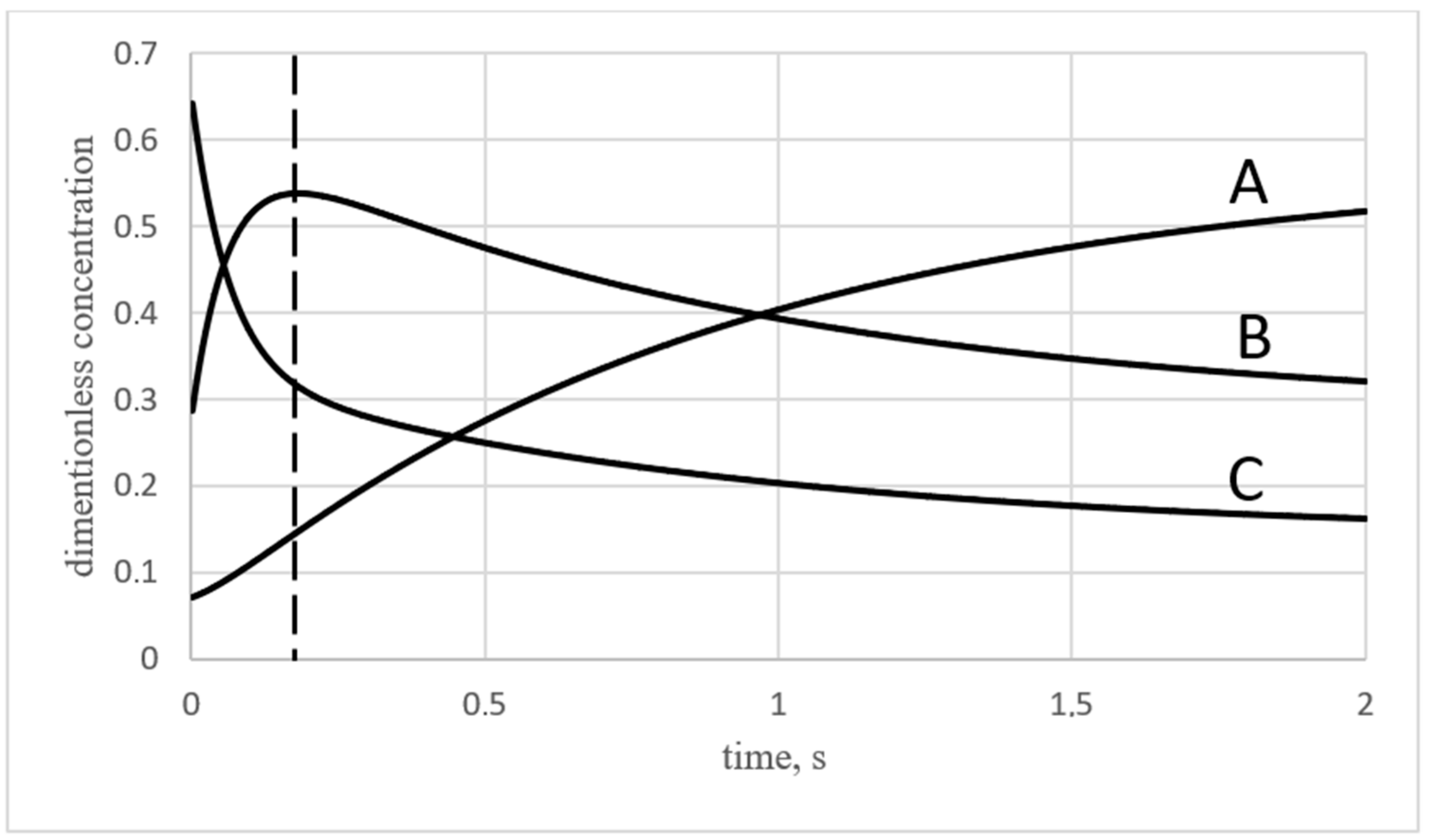
- Introduce perturbations: Some of the species, at least two, are chosen to have their concentration modified from the equilibrium value by some delta.
- Ensure conservation law: The perturbations are required to satisfy the conservation of chemical element amounts.
1.2. Methane Reforming Processes and CPE Application
- Steam reforming of methane (SRM) is the most widely used method for methane reforming. It involves reacting methane with steam in the presence of a catalyst to produce hydrogen and carbon monoxide. SMR is extensively employed for large-scale hydrogen production, which finds applications in fuel cells, chemical synthesis, and refining processes.
- Dry reforming of methane (DRM) differs from steam reforming in that it uses carbon dioxide instead of steam as the reactant. This process is particularly interesting because it can utilize two abundant greenhouse gases, methane and carbon dioxide, to produce valuable syngas (mixture of hydrogen and carbon monoxide). However, dry reforming is technically challenging due to thermodynamic constraints and the tendency for carbon formation (coking) on catalysts.
- Autothermal reforming of methane (ATR) combines elements of both steam reforming and partial oxidation. It involves reacting methane with both steam and oxygen, typically in a single reactor, with the assistance of a catalyst. ATR offers the advantages of both steam reforming (high hydrogen yield) and partial oxidation (simplicity and flexibility).
- Twenty years ago, a novel process concept called the tri-reforming of methane was proposed by Song and Pan [7]. This new process is aimed at utilizing CO2 contained in fossil fuel-based power plant flue gases without the need to separate it from the mixture. Tri-reforming of methane is a combination of three separate reforming reactions in one reacting space. These reactions include endothermic dry reforming, steam reforming, and the exothermic partial oxidation of methane. Both experiments and computational analysis performed by Song and Pan show that in addition to producing syngas (CO + H2) with desired H2/CO ratios of 1.5–2.0, tri-reforming can also reduce carbon formation—a serious problem encountered in the dry reforming process. These two advantages have been demonstrated by tri-reforming CH4 in a fixed-bed flow reactor at 850 C with supported nickel catalysts. Studies show that more than 95% CH4 conversion and 80% CO2 conversion can be achieved via tri-reforming over Ni catalysts on an oxide substrate [8]. In one of the last reviews on the tri-forming process [9,10], it is stated that steam reforming of methane (SRM) and partial oxidation of methane (POM) has been deployed at large industrial scale, while dry reforming of methane (DRM) and, more recently, tri-reforming of methane (TRM) are intensively studied. In the review, the uniqueness of TRM is determined as follows: it simultaneously combines SRM, POM, and DRM in one process and allows for overcoming several weaknesses of each individual methane reforming process: e.g., regulation of the molar ratio of H2/CO by controlling feed composition; adaptation to the variation in biogas composition as renewable resource. However, to date, the design of efficient TRM catalysts remains a challenge.
2. Results
- CO2: CO: H2: CH4: H2O = 1: 0: 0: 2: 1 (mole fractions).
- Calculated equilibrium concentrations are listed in Table 3.
3. Discussions
4. Modeling and It’s Methods
5. Conclusions
Author Contributions
Funding
Data Availability Statement
Acknowledgments
Conflicts of Interest
References
- Zel’dovich, Y.B. Selected Works of Yakov Borisovich Zeldovich: Chemical Physics and Hydrodynamics: Proof of the Uniqueness of the Solutions of the Equations of the Law of Mass Action; Princeton University Press: Princeton, NJ, USA, 2014. [Google Scholar]
- Yablonsky, G.S.; Branco, D.P.; Marin, G.B.; Constales, D. Conservatively Perturbed Equilibrium (CPE) in chemical kinetics. Chem. Eng. Sci. 2019, 196, 384–390. [Google Scholar] [CrossRef]
- Yiming, X.; Xinquan, L.; Constales, D.; Yablonsky, G.S. Perturbed and Unperturbed: Analyzing the Conservatively Perturbed Equilibrium (Linear Case). Entropy 2020, 22, 1160. [Google Scholar] [CrossRef] [PubMed]
- Yablonsky, G.S.; Gorban, A.N.; Constales, D.; Galvita, V.V.; Marin, G.B. Reciprocal relations between kinetic curves. EuroPhys. Lett. 2011, 66, 20004. [Google Scholar] [CrossRef]
- Trishch, V.R.; Beznosyk, Y.O.; Yablonsky, G.S.; Constales, D. The phenomenon of conservative perturbed equilibrium in multi-route catalytic systems, Bulletin of NTUU “Igor Sikorsky Kyiv Polytechnic Institute”. Ser. Chem. Eng. Ecol. Resour. Conserv. 2022, 3, 39–55. [Google Scholar] [CrossRef]
- Trishch, V.R.; Beznosyk, Y.O.; Yablonsky, G.S.; Constales, D. The phenomenon of conservative-perturbed equilibrium in conditions different reactors, Bulletin of NTUU “Igor Sikorsky Kyiv Polytechnic Institute”. Ser. Chem. Eng. Ecol. Resour. Conserv. 2021, 1, 38–46. [Google Scholar] [CrossRef]
- Song, C.; Pan, W. Tri-reforming of methane: A novel concept for catalytic production of industrially useful synthesis gas with desired H2/CO ratios. Catal. Today 2004, 98, 463–484. [Google Scholar] [CrossRef]
- Soleimani, S.; Lehner, M. Tri-Reforming of Methane: Thermodynamics, Operating Conditions, Reactor Technology and Efficiency Evaluation—A Review. Energies 2022, 15, 7159. [Google Scholar] [CrossRef]
- Minh, P.; Pham, X.-H.; Siang, T.J.; Vo, D.-V.N. Review on the catalytic tri-reforming of methane—Part I: Impact of operating conditions, catalyst deactivation and regeneration. Appl. Catal. A Gen. 2021, 621, 118202. [Google Scholar] [CrossRef]
- Pham, X.H.; Ashik UP, M.; Hayashi, J.I.; Alonso, A.P.; Pla, D.; Gómez, M.; Minh, D.P. Review on the catalytic tri-reforming of methane—Part II: Catalyst development. Appl. Catal. A Gen. 2021, 623, 118286. [Google Scholar] [CrossRef]
- Osat, M.; Shojaati, F. Assessing performance of methane tri-reforming reactor using a parametric study on the fundamental process variables. Clean. Chem. Eng. 2022, 3, 100050. [Google Scholar] [CrossRef]
- Lari, M.F.; Farsi, M.; Rahimpour, M.R. Modification of a tri-reforming reactor based on the feeding policy to couple with methanol and GTL units. Chem. Eng. Res. Des. 2019, 144, 107–114. [Google Scholar] [CrossRef]
- Wei, J.; Iglesia, E. Isotopic and kinetic assessment of the mechanism of reactions of CH4 with CO2 or H2O to form synthesis gas and carbon on nickel catalysts. J. Catal. 2004, 224, 370–383. [Google Scholar] [CrossRef]


| Unperturbed Species | Perturbed Species | Initial Concentrations |
|---|---|---|
| Number | Reaction | ∆H298 (kJ/mole) | Description |
|---|---|---|---|
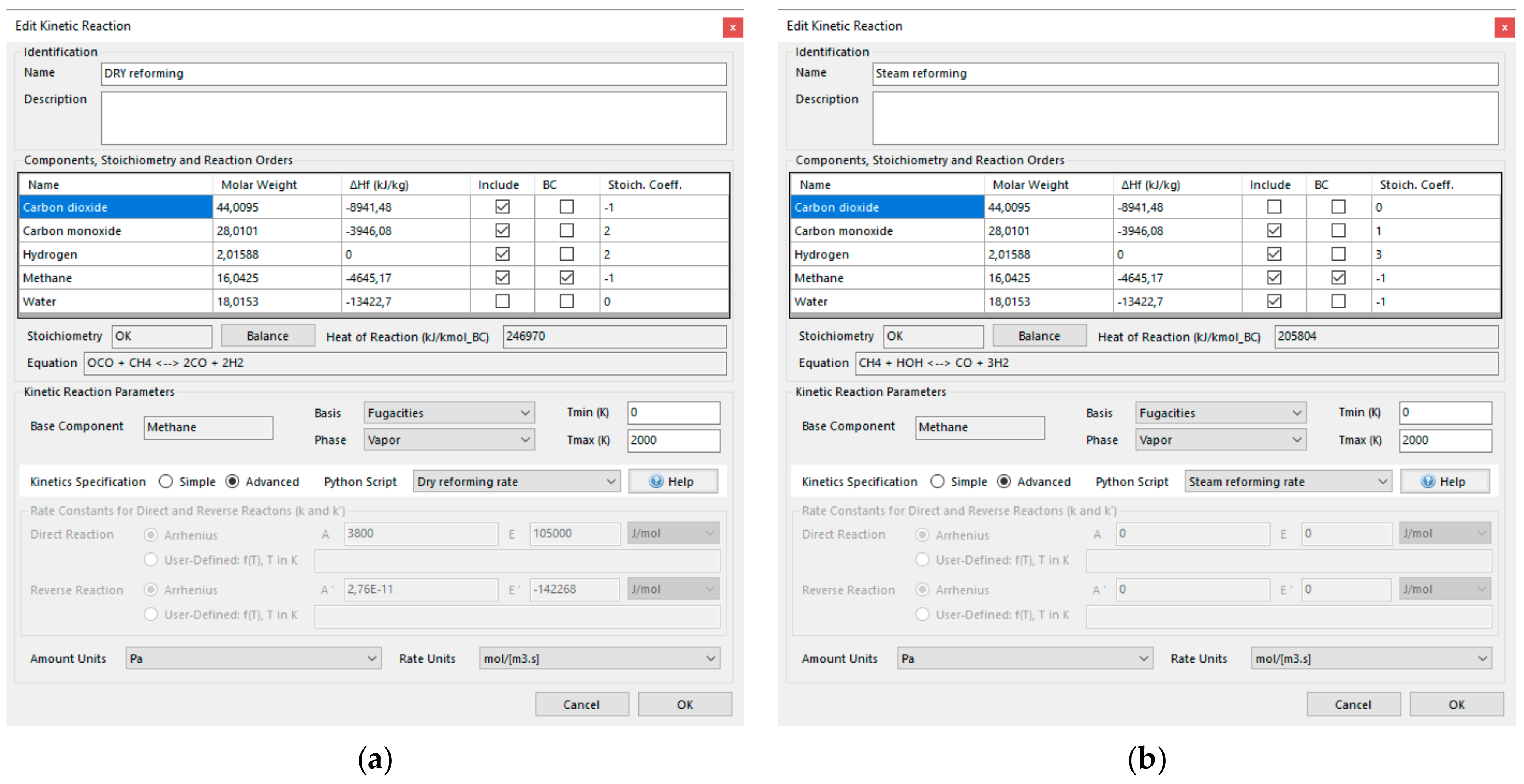
| 1 | CH4 + CO2 ↔ 2CO + 2H2 | +247 | Dry reforming (reversible reaction) |
| 2 | CH4 + H2O ↔ CO + 3H2 | +206 | Steam reforming (reversible reaction) |
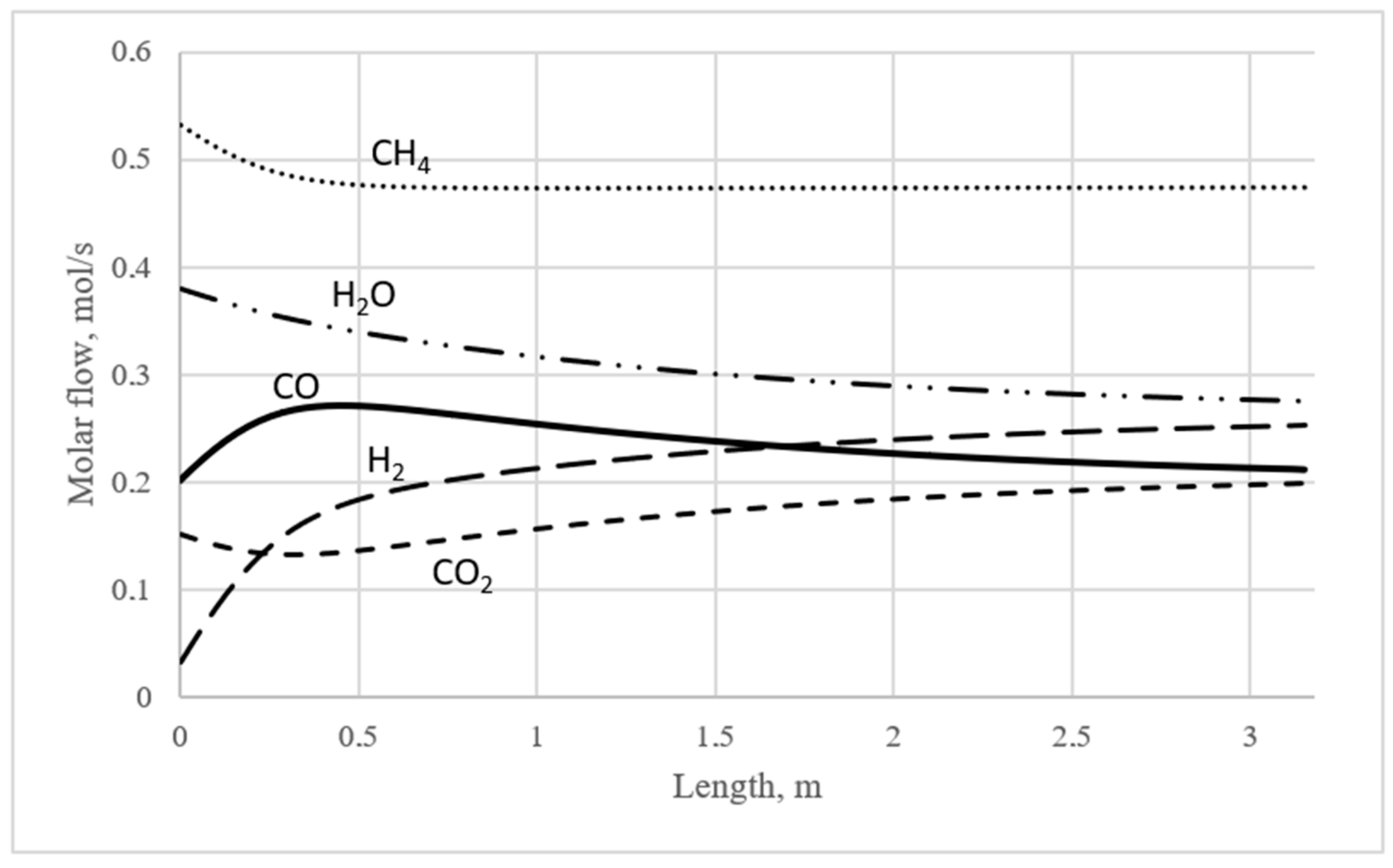
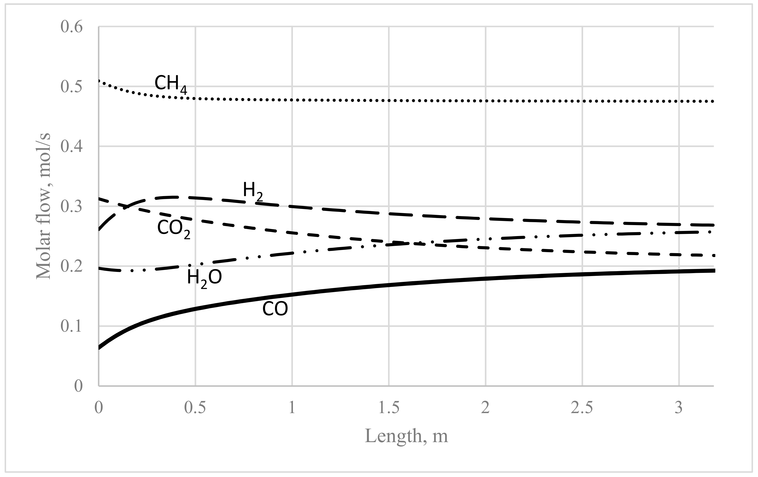
| 973.15 K | |||
|---|---|---|---|
| Compound | Exit Molar Flow Rate, mol/s | Perturbed Molar Flow Rate (CO Unperturbed), mol/s | Perturbed Molar Flow Rate (H2 Unperturbed), mol/s |
| CO2 | 0.206 | 0.152 | 0.313 |
| CO | 0.201 | 0.201 (unperturbed) | 0.064 |
| H2 | 0.261 | 0.032 | 0.261 (unperturbed) |
| CH4 | 0.475 | 0.532 | 0.509 |
| H2O | 0.265 | 0.379 | 0.197 |
| Check of elemental balances | |||
| C (moles) | 77.38 | 77.38 | 77.38 |
| H (moles) | 257.93 | 257.93 | 257.93 |
| O (moles) | 77.38 | 77.38 | 77.38 |
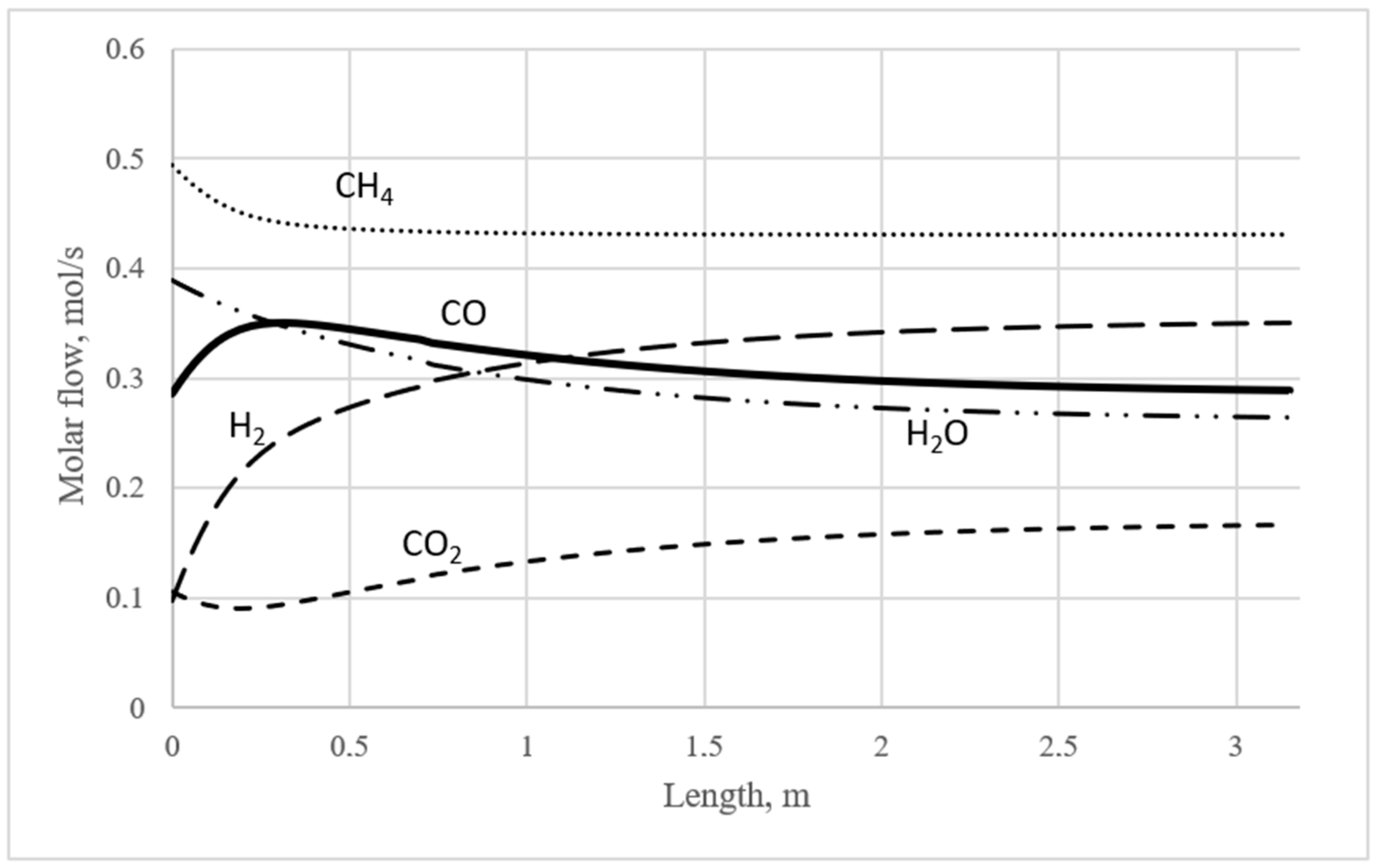
| 1023.15 K | |||
| Compound | Exit Molar Flow Rate, mol/s | Perturbed Mole Flow (CO Unperturbed), mol/s | Perturbed Mole Flow (H2 Unperturbed), mol/s |
| CO2 | 0.169 | 0.105 | 0.284 |
| CO | 0.286 | 0.286 (unperturbed) | 0.132 |
| H2 | 0.353 | 0.097 | 0.353 (unperturbed) |
| CH4 | 0.431 | 0.496 | 0.469 |
| H2O | 0.261 | 0.389 | 0.185 |
| Check of elemental balances | |||
| C | 69.26 | 69.26 | 69.26 |
| H | 230.85 | 230.85 | 230.85 |
| O | 69.26 | 69.26 | 69.26 |
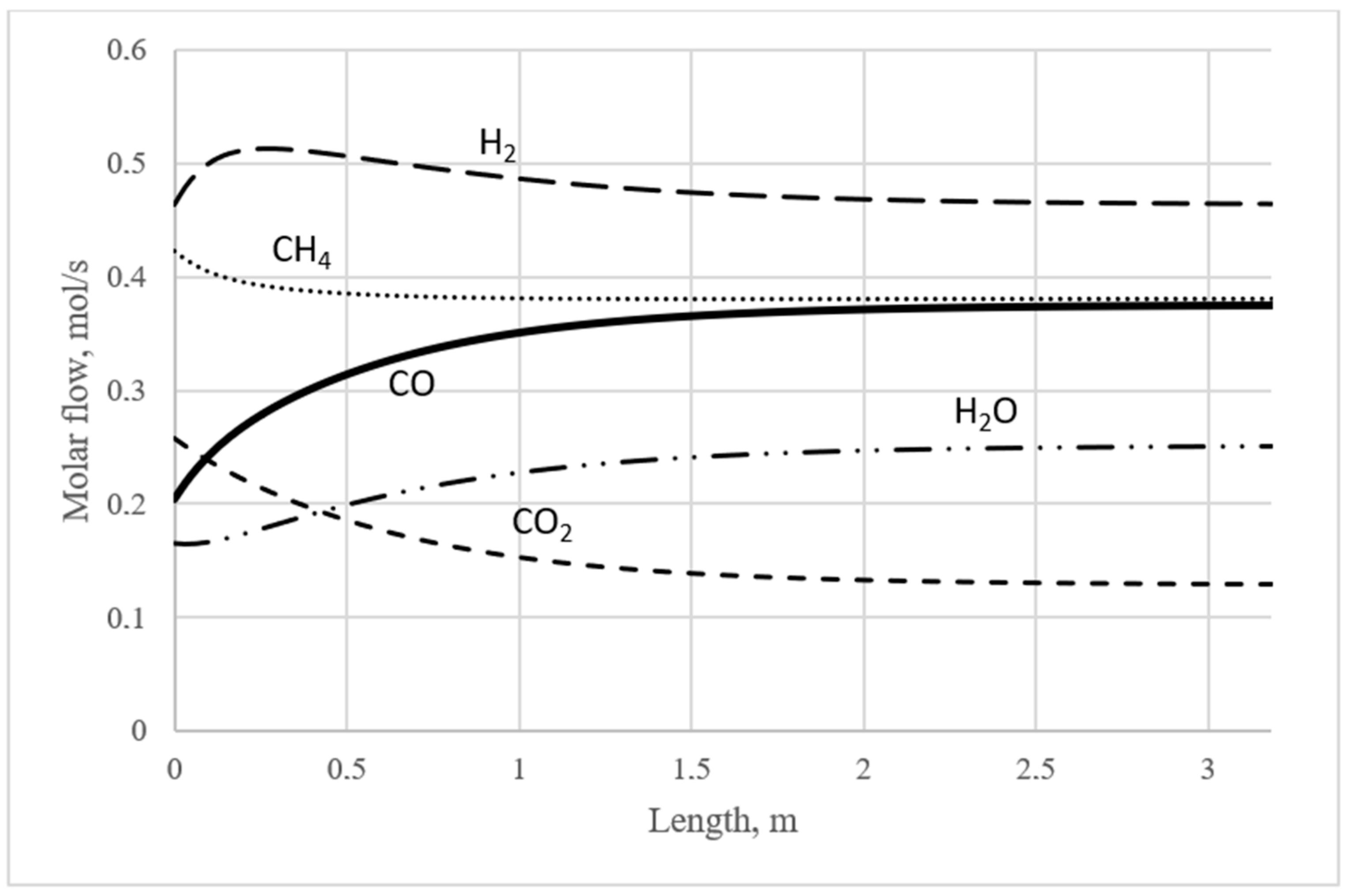
| 1073.15 K | |||
| Compound | Equilibrium Concentration, mol/m3 | Perturbed Concentration (CO Unperturbed), mol/m3 | Perturbed Concentration (H2 Unperturbed), mol/m3 |
| CO2 | 0.130 | 0.058 | 0.258 |
| CO | 0.376 | 0.376 (unperturbed) | 0.204 |
| H2 | 0.464 | 0.178 | 0.464 (unperturbed) |
| CH4 | 0.380 | 0.452 | 0.423 |
| H2O | 0.251 | 0.394 | 0.165 |
| Check of elemental balances | |||
| C | 61.88 | 61.88 | 61.88 |
| H | 206.27 | 206.27 | 206.27 |
| O | 61.88 | 61.88 | 61.88 |
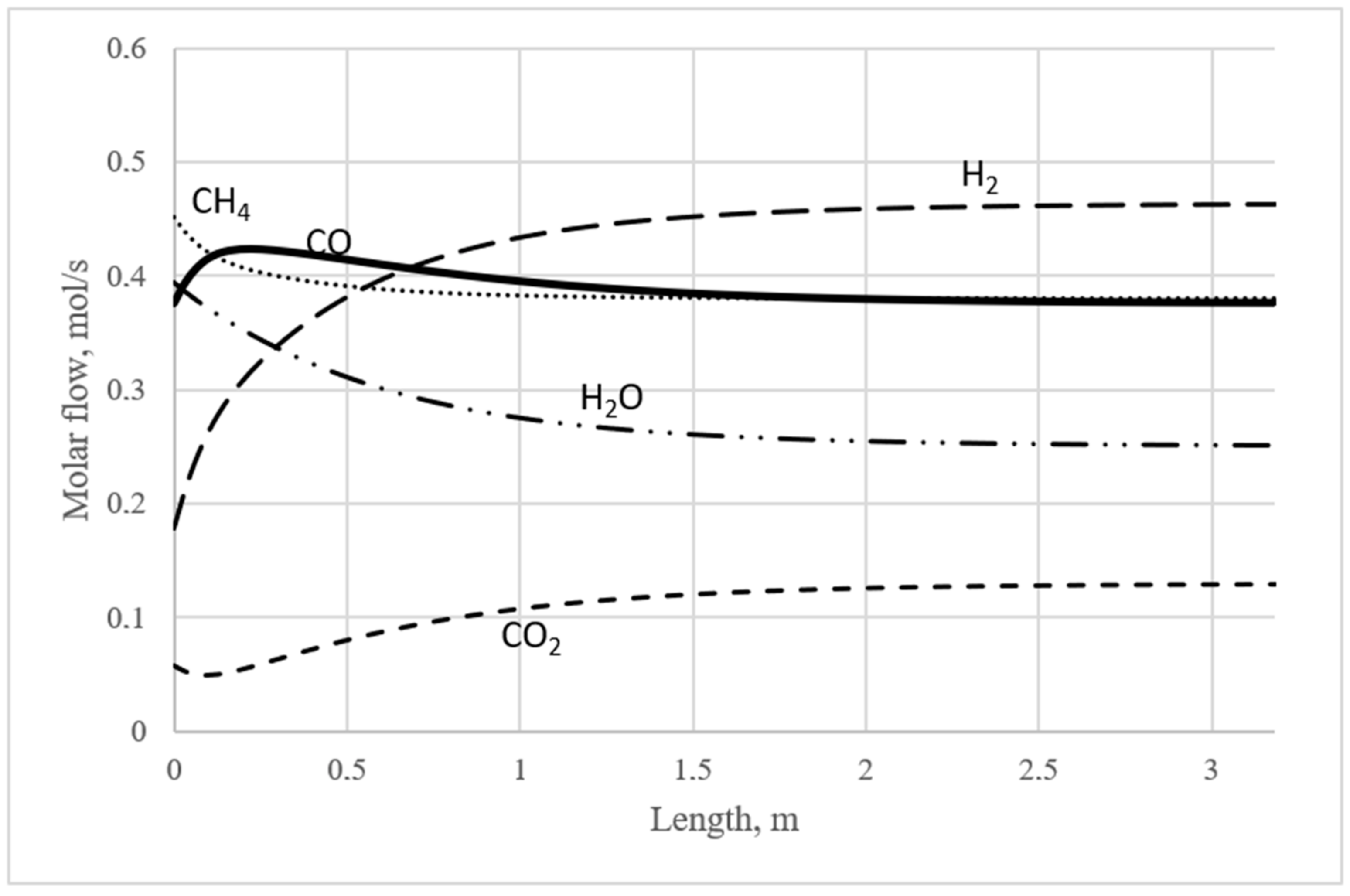
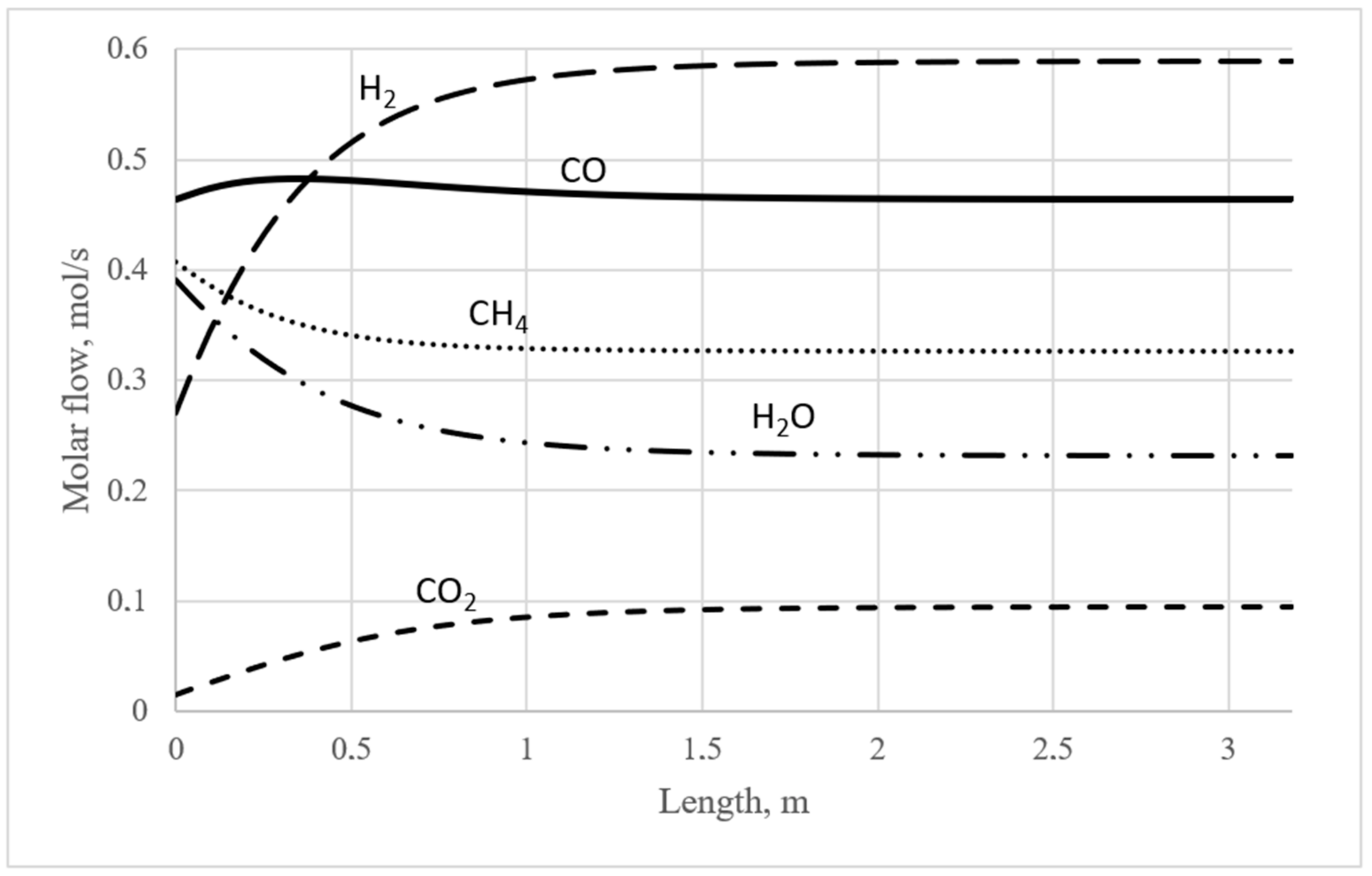
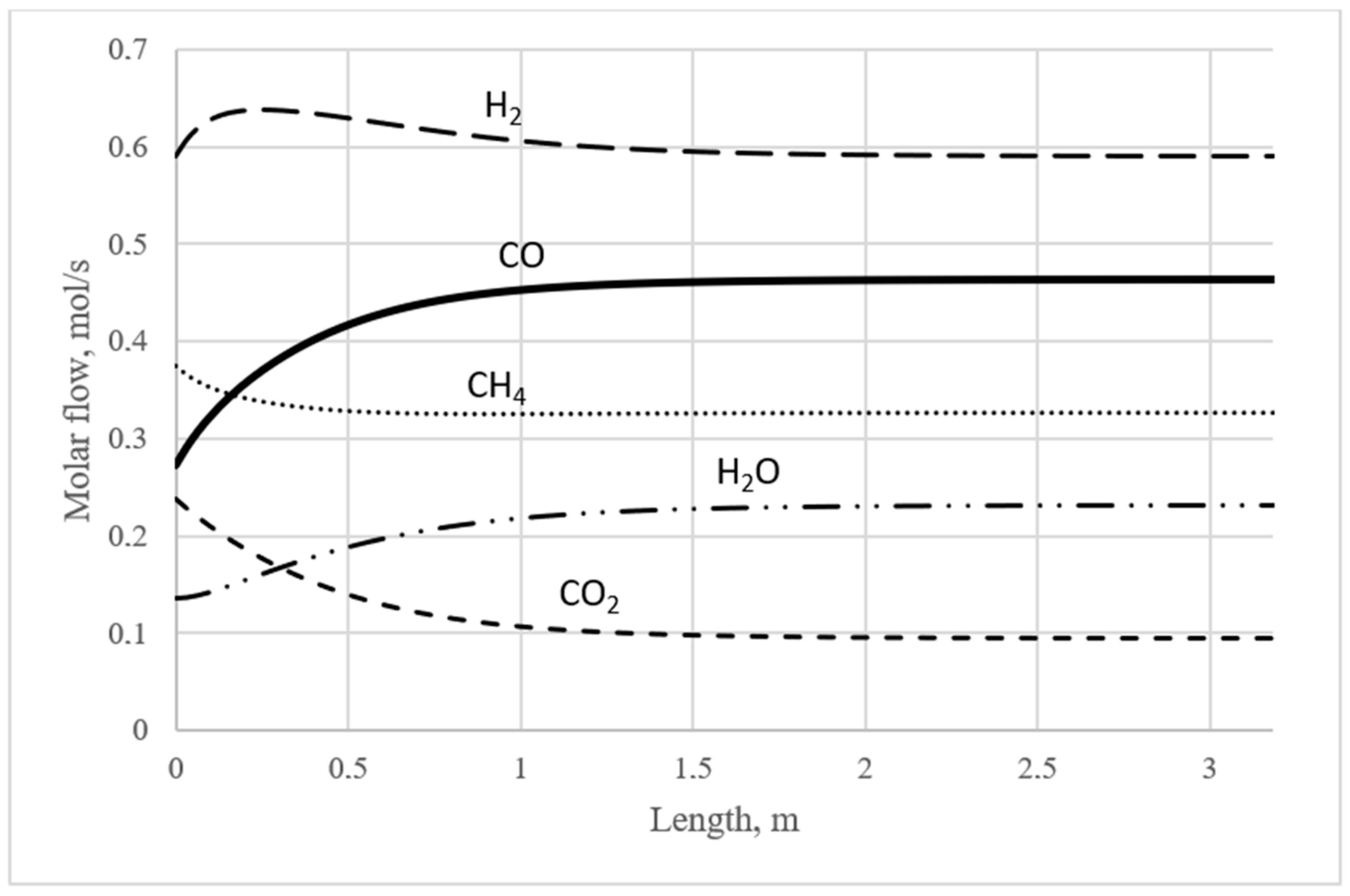
| 1123.15 K | |||
| Compound | Equilibrium Concentration, mol/m3 | Perturbed Concentration (CO Unperturbed), mol/m3 | Perturbed Concentration (H2 Unperturbed), mol/m3 |
| CO2 | 0.095 | 0.015 | 0.239 |
| CO | 0.464 | 0.464 (unperturbed) | 0.272 |
| H2 | 0.590 | 0.270 | 0.590 (unperturbed) |
| CH4 | 0.327 | 0.407 | 0.375 |
| H2O | 0.232 | 0.392 | 0.136 |
| Check of elemental balances | |||
| C | 55.48 | 55.48 | 55.48 |
| H | 184.75 | 184.75 | 184.75 |
| O | 55.48 | 55.48 | 55.48 |
| T, K | OE Molar Flow Rate, Excess for CO, % | OE Molar Flow Rate, Excess for H2, % | OE Molar Flow Rate, Absolute Value for CO, mol/s | OE Molar Flow Rate, Absolute Value for H2, mol/s | OE Position for CO, Relative Length (LCPE/Leq) | OE Position for H2, Relative Length (LCPE/Leq) |
|---|---|---|---|---|---|---|
| 973 | 35.1 | 20.6 | 0.272 | 0.315 | 0.08 | 0.13 |
| 1023 | 22.7 | 14.2 | 0.351 | 0.403 | 0.10 | 0.14 |
| 1073 | 12.7 | 10.6 | 0.423 | 0.513 | 0.11 | 0.14 |
| 1123 | 4.1 | 8.1 | 0.482 | 0.638 | 0.12 | 0.17 |
| Object | Parameters |
|---|---|
| Input | Temperature: 973.15–1123.15 K with 50 K intervals. |
| Pressure: 10 bar | |
| Mass flow: 100 kg/h | |
| Compound amounts: should be defined for each individual experimental case following the CPE principle described in the Introduction Section (Section 1). | |
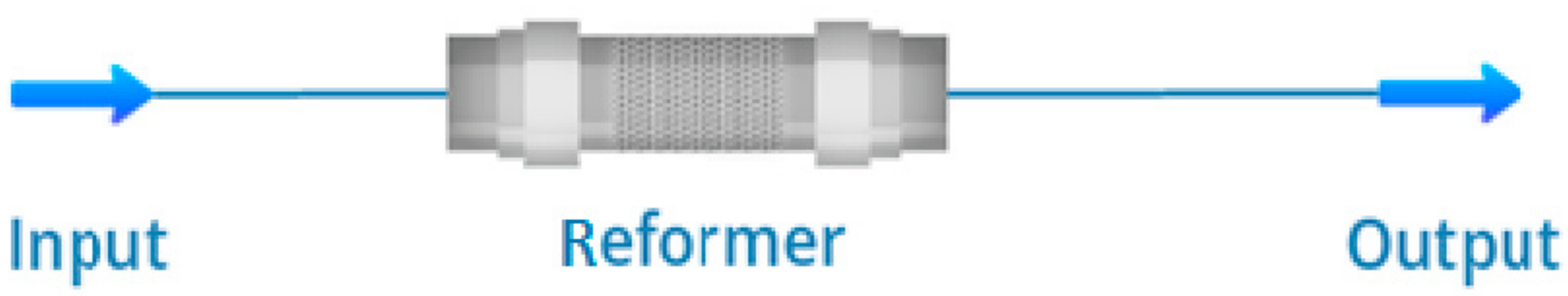
| Reformer | Reaction Set: Default Set |
| Calculation Mode: Isothermic Property Package: Peng–Robinson Reactive Volume: 0.1 m3 Tube Diameter: 200 mm | |
| Output | Every other parameter is defined either by Input or by Reformer |
Disclaimer/Publisher’s Note: The statements, opinions and data contained in all publications are solely those of the individual author(s) and contributor(s) and not of MDPI and/or the editor(s). MDPI and/or the editor(s) disclaim responsibility for any injury to people or property resulting from any ideas, methods, instructions or products referred to in the content. |
© 2024 by the authors. Licensee MDPI, Basel, Switzerland. This article is an open access article distributed under the terms and conditions of the Creative Commons Attribution (CC BY) license (https://creativecommons.org/licenses/by/4.0/).
Share and Cite
Vilboi, M.O.; Trishch, V.R.; Yablonsky, G.S. Conservatively Perturbed Equilibrium (CPE)—Phenomenon as a Tool for Intensifying the Catalytic Process: The Case of Methane Reforming Processes. Catalysts 2024, 14, 395. https://doi.org/10.3390/catal14070395
Vilboi MO, Trishch VR, Yablonsky GS. Conservatively Perturbed Equilibrium (CPE)—Phenomenon as a Tool for Intensifying the Catalytic Process: The Case of Methane Reforming Processes. Catalysts. 2024; 14(7):395. https://doi.org/10.3390/catal14070395
Chicago/Turabian StyleVilboi, Mykhailo O., Vitaliy R. Trishch, and Gregory S. Yablonsky. 2024. "Conservatively Perturbed Equilibrium (CPE)—Phenomenon as a Tool for Intensifying the Catalytic Process: The Case of Methane Reforming Processes" Catalysts 14, no. 7: 395. https://doi.org/10.3390/catal14070395
APA StyleVilboi, M. O., Trishch, V. R., & Yablonsky, G. S. (2024). Conservatively Perturbed Equilibrium (CPE)—Phenomenon as a Tool for Intensifying the Catalytic Process: The Case of Methane Reforming Processes. Catalysts, 14(7), 395. https://doi.org/10.3390/catal14070395