
Surface Modification towards Integral Bulk Catalysts of Transition Metal Borides for Hydrogen Evolution Reaction

 , and
, and 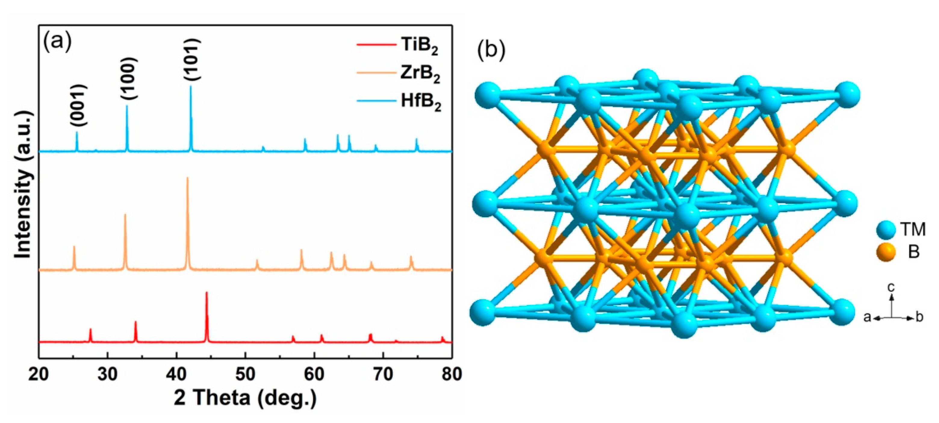
Abstract
1. Introduction
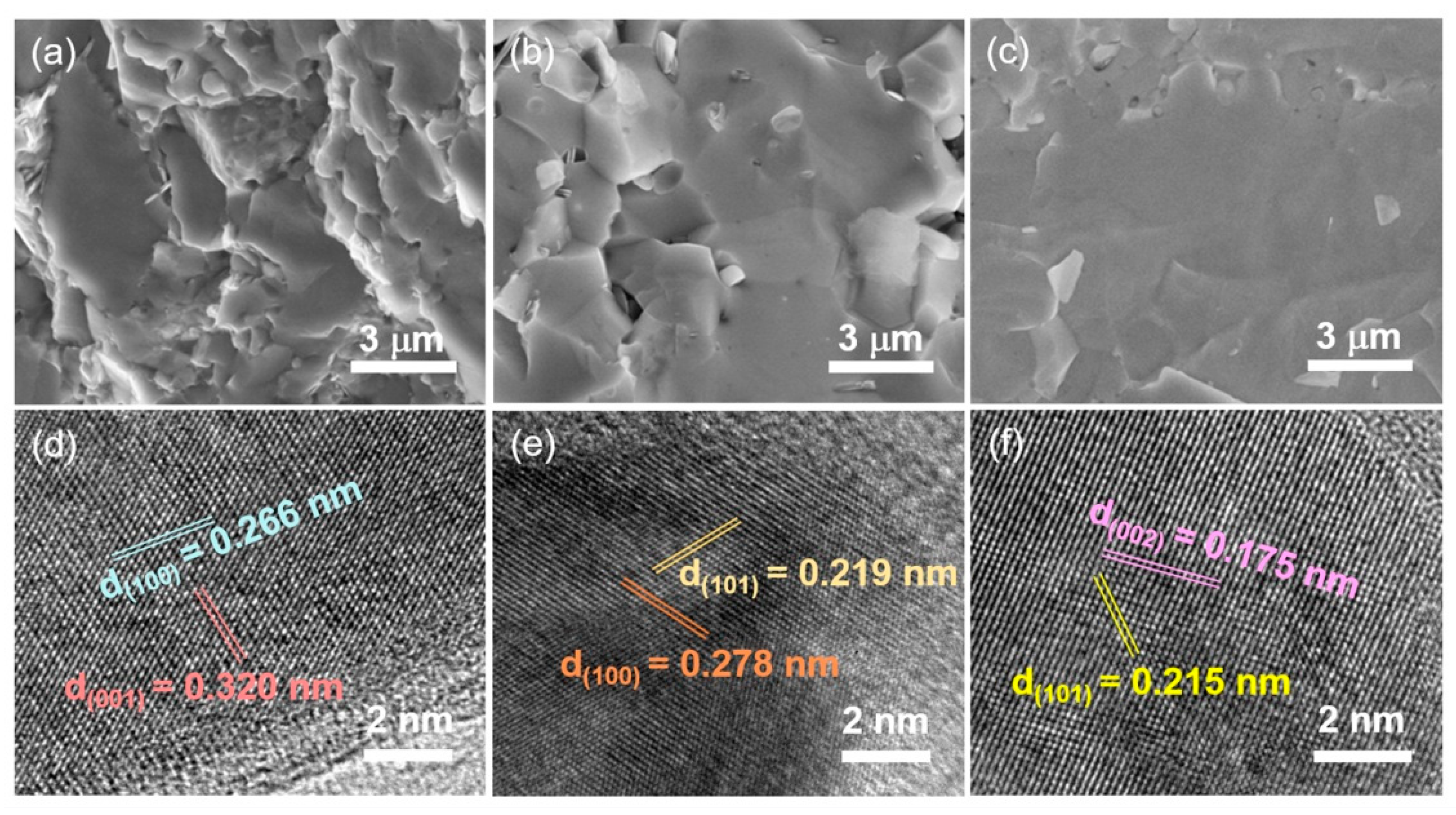
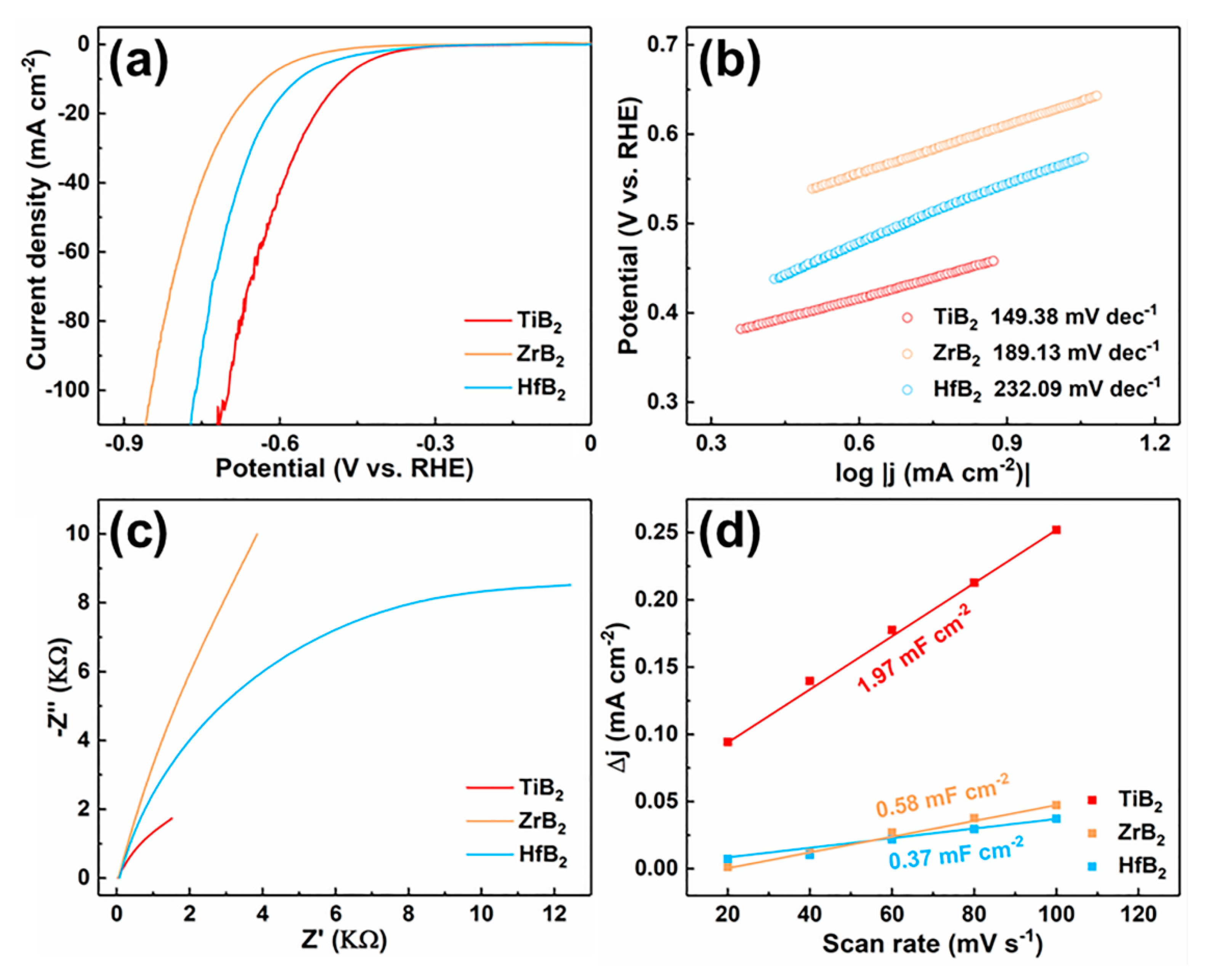
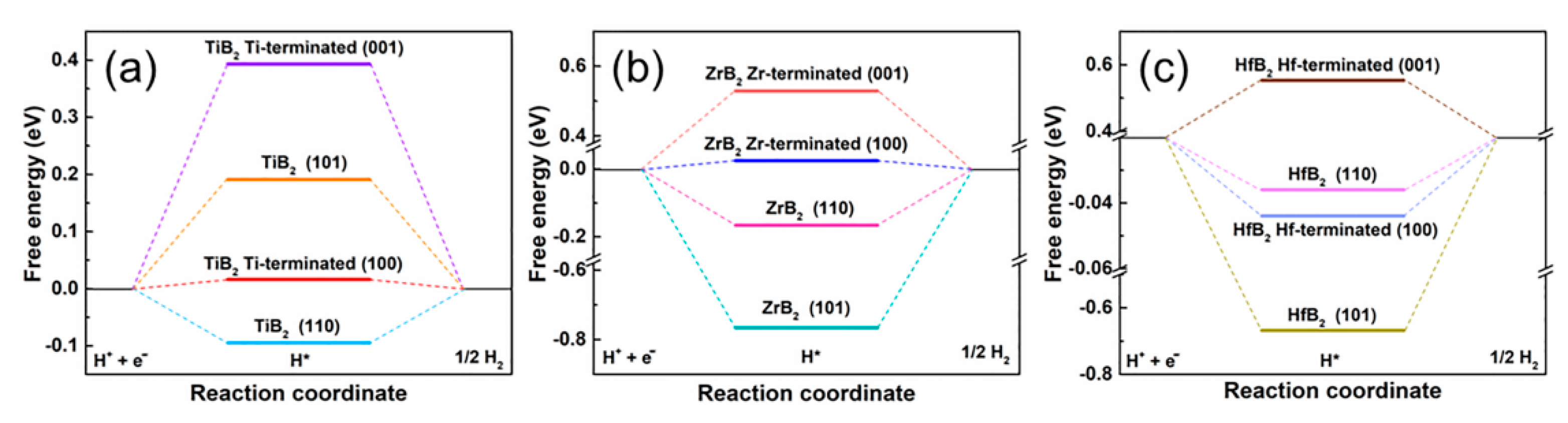
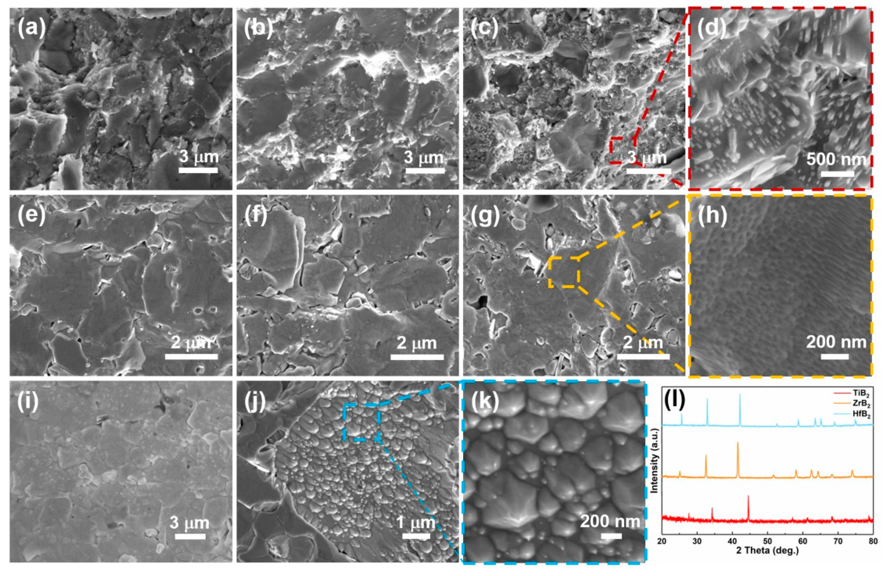
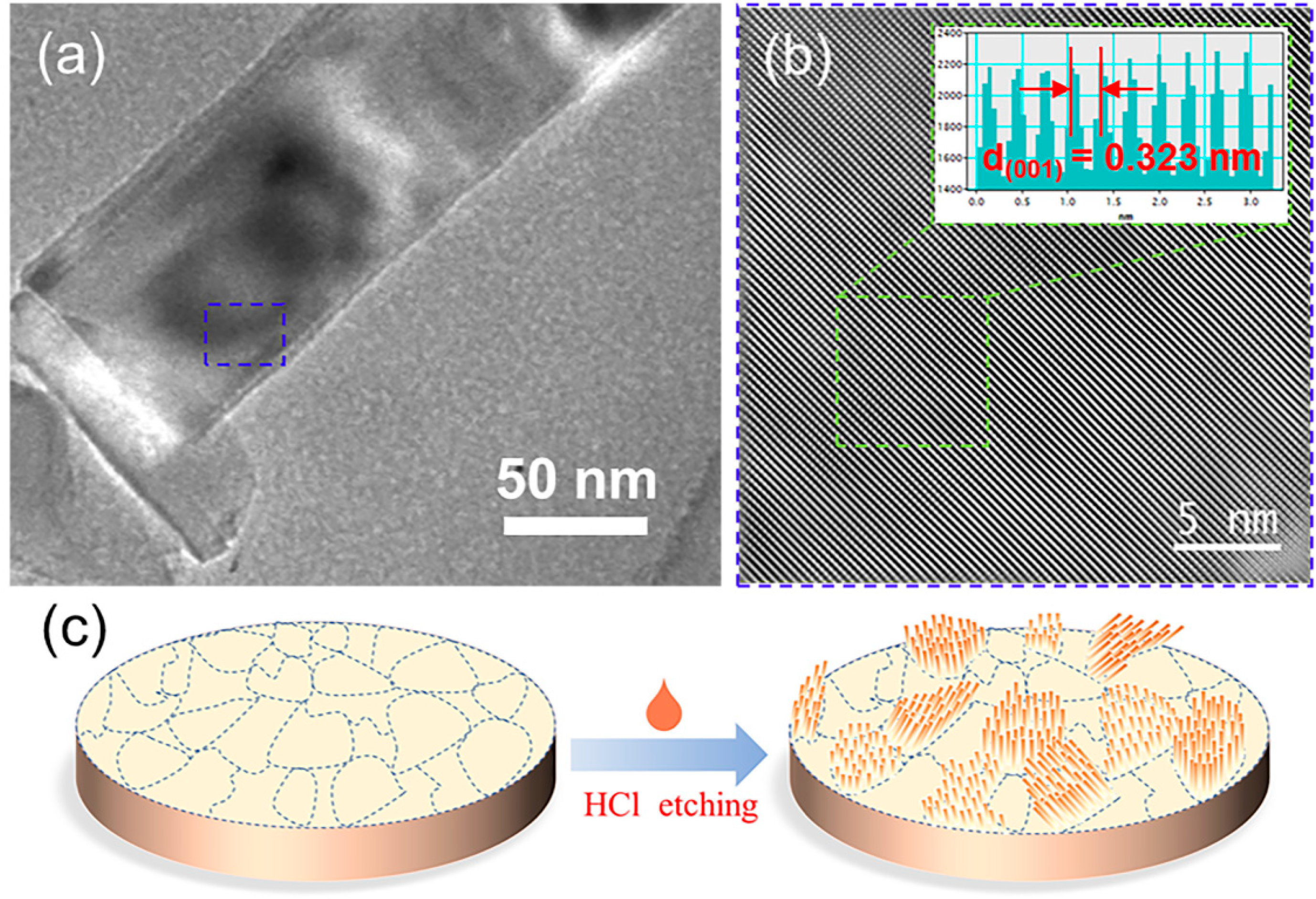
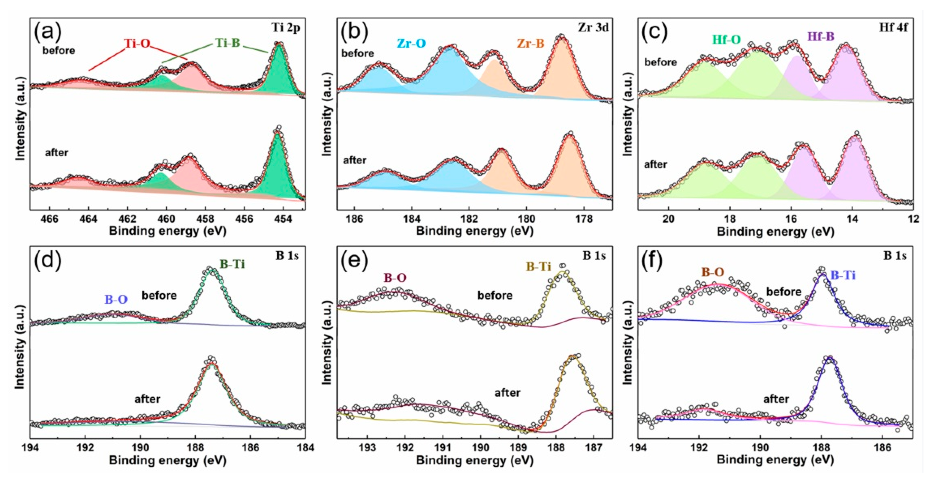
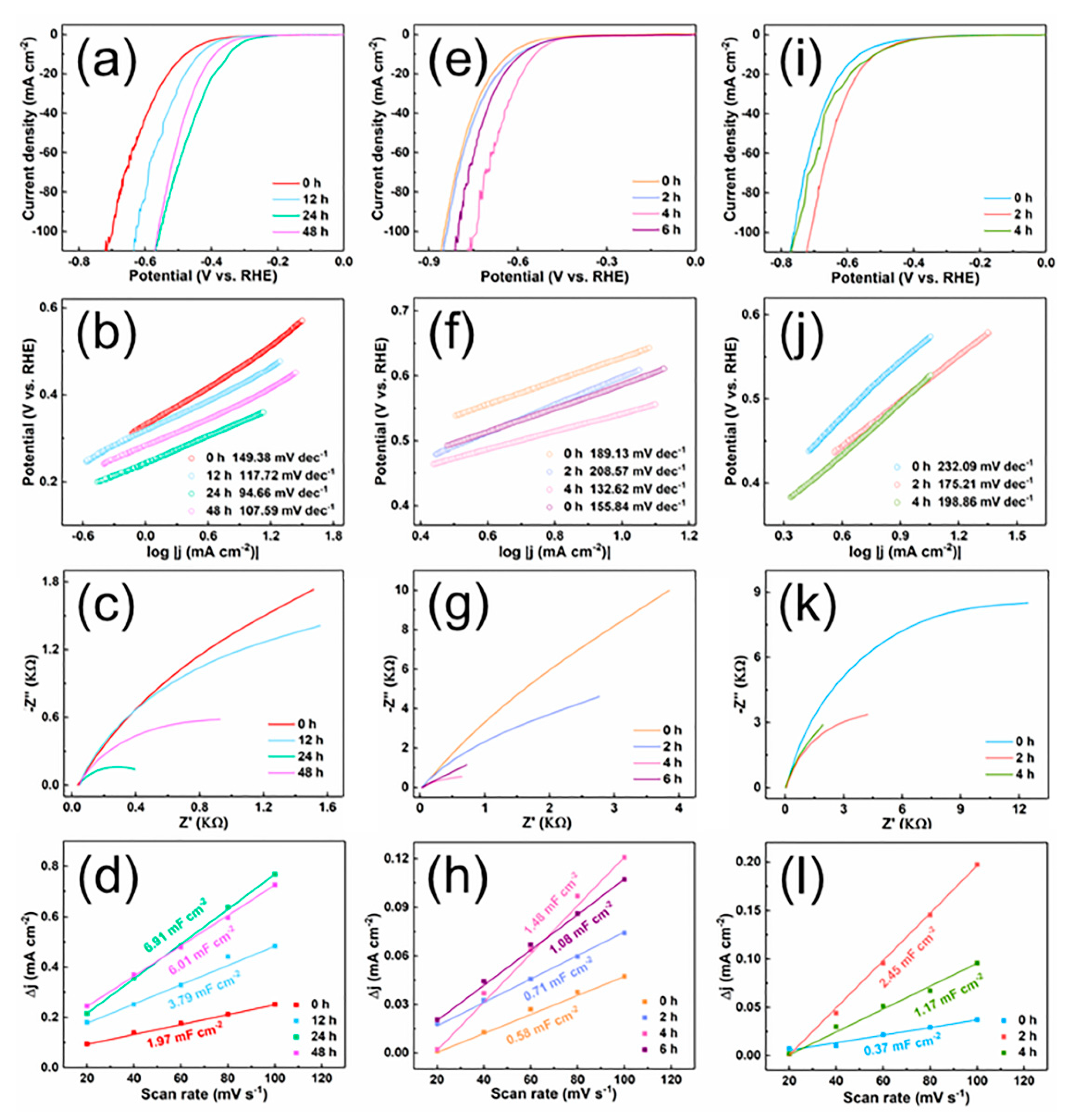
2. Results and Discussion
3. Materials and Methods
3.1. Materials
3.2. Preparation of TiB2, ZrB2 and HfB2 Bulk Materials
3.3. Constructed the Surface Morphology of TiB2, ZrB2 and HfB2 Bulk Materials
3.4. Characterization
3.5. Preparation of the Working Electrode
3.6. Electrochemical Measurement
3.7. DFT Calculations
4. Conclusions
Supplementary Materials
Author Contributions
Funding
Data Availability Statement
Conflicts of Interest
References
- Nielsen, M.; Alberico, E.; Baumann, W.; Drexler, H.-J.; Junge, H.; Gladiali, S.; Beller, M. Low-temperature aqueous-phase methanol dehydrogenation to hydrogen and carbon dioxide. Nature 2013, 495, 85–89. [Google Scholar] [CrossRef] [PubMed]
- Hosseini, S.E.; Wahid, M.A. Hydrogen production from renewable and sustainable energy resources: Promising green energy carrier for clean development. Renew. Sustain. Energy Rev. 2016, 57, 850–866. [Google Scholar] [CrossRef]
- Wang, X.; Maeda, K.; Thomas, A.; Takanabe, K.; Xin, G.; Carlsson, J.M.; Domen, K.; Antonietti, M. A metal-free polymeric photocatalyst for hydrogen production from water under visible light. Nat. Mater. 2009, 8, 76–80. [Google Scholar] [CrossRef]
- Kudo, A.; Miseki, Y. Heterogeneous photocatalyst materials for water splitting. Chem. Soc. Rev. 2009, 38, 253–278. [Google Scholar] [CrossRef] [PubMed]
- Li, Y.; Wang, H.; Xie, L.; Liang, Y.; Hong, G.; Dai, H. MoS2 Nanoparticles Grown on Graphene: An Advanced Catalyst for the Hydrogen Evolution Reaction. J. Am. Chem. Soc. 2011, 133, 7296–7299. [Google Scholar] [CrossRef]
- Landman, A.; Dotan, H.; Shter, G.E.; Wullenkord, M.; Houaijia, A.; Maljusch, A.; Grader, G.S.; Rothschild, A. Photoelectrochemical water splitting in separate oxygen and hydrogen cells. Nat. Mater. 2017, 16, 646–651. [Google Scholar] [CrossRef]
- Chi, J.; Yu, H. Water electrolysis based on renewable energy for hydrogen production. Chin. J. Catal. 2018, 39, 390–394. [Google Scholar] [CrossRef]
- Wang, J.; Cui, W.; Liu, Q.; Xing, Z.; Asiri, A.M.; Sun, X. Recent Progress in Cobalt-Based Heterogeneous Catalysts for Electrochemical Water Splitting. Adv. Mater. 2016, 28, 215–230. [Google Scholar] [CrossRef]
- Zou, X.; Zhang, Y. Noble metal-free hydrogen evolution catalysts for water splitting. Chem. Soc. Rev. 2015, 44, 5148–5180. [Google Scholar] [CrossRef]
- Ledezma-Yanez, I.; Wallace, W.D.Z.; Sebastián-Pascual, P.; Climent, V.; Feliu, J.M.; Koper, M.T.M. Interfacial water reorganization as a pH-dependent descriptor of the hydrogen evolution rate on platinum electrodes. Nat. Energy 2017, 2, 17031. [Google Scholar] [CrossRef]
- Arif, M.; Yasin, G.; Shakeel, M.; Mushtaq, M.A.; Ye, W.; Fang, X.; Ji, S.; Yan, D. Highly active sites of NiVB nanoparticles dispersed onto graphene nanosheets towards efficient and pH-universal overall water splitting. J. Energy Chem. 2021, 58, 237–246. [Google Scholar] [CrossRef]
- Liu, C.; Gong, T.; Zhang, J.; Zheng, X.; Mao, J.; Liu, H.; Li, Y.; Hao, Q. Engineering Ni2P-NiSe2 heterostructure interface for highly efficient alkaline hydrogen evolution. Appl. Catal. B Environ. 2020, 262, 118245. [Google Scholar] [CrossRef]
- Anantharaj, S.; Kundu, S.; Noda, S. Progress in nickel chalcogenide electrocatalyzed hydrogen evolution reaction. J. Mater. Chem. A 2020, 8, 4174–4192. [Google Scholar] [CrossRef]
- Liu, Y.; Vijayakumar, P.; Liu, Q.; Sakthivel, T.; Chen, F.; Dai, Z. Shining Light on Anion-Mixed Nanocatalysts for Efficient Water Electrolysis: Fundamentals, Progress, and Perspectives. Nano-Micro Lett. 2022, 14, 43. [Google Scholar] [CrossRef]
- Lin, Z.; Xiao, B.; Wang, Z.; Tao, W.; Shen, S.; Huang, L.; Zhang, J.; Meng, F.; Zhang, Q.; Gu, L.; et al. Planar-Coordination PdSe2 Nanosheets as Highly Active Electrocatalyst for Hydrogen Evolution Reaction. Adv. Funct. Mater. 2021, 31, 2102321. [Google Scholar] [CrossRef]
- Wei, Y.; Soomro, R.A.; Xie, X.; Xu, B. Design of efficient electrocatalysts for hydrogen evolution reaction based on 2D MXenes. J. Energy Chem. 2021, 55, 244–255. [Google Scholar] [CrossRef]
- Wang, M.; Zhang, L.; He, Y.; Zhu, H. Recent advances in transition-metal-sulfide-based bifunctional electrocatalysts for overall water splitting. J. Mater. Chem. A 2021, 9, 5320–5363. [Google Scholar] [CrossRef]
- Theerthagiri, J.; Murthy, A.P.; Lee, S.J.; Karuppasamy, K.; Arumugam, S.R.; Yu, Y.; Hanafiah, M.M.; Kim, H.-S.; Mittal, V.; Choi, M.Y. Recent progress on synthetic strategies and applications of transition metal phosphides in energy storage and conversion. Ceram. Int. 2021, 47, 4404–4425. [Google Scholar] [CrossRef]
- Theerthagiri, J.; Lee, S.J.; Murthy, A.P.; Madhavan, J.; Choi, M.Y. Fundamental aspects and recent advances in transition metal nitrides as electrocatalysts for hydrogen evolution reaction: A review. Curr. Opin. Solid State Mater. Sci. 2020, 24, 100805. [Google Scholar] [CrossRef]
- Zeng, M.; Li, Y. Recent advances in heterogeneous electrocatalysts for the hydrogen evolution reaction. J. Mater. Chem. A 2015, 3, 14942–14962. [Google Scholar] [CrossRef]
- Lee, E.; Fokwa, B.P.T. Nonprecious Metal Borides: Emerging Electrocatalysts for Hydrogen Production. Acc. Chem. Res. 2022, 55, 56–64. [Google Scholar] [CrossRef] [PubMed]
- Huang, H.; Jung, H.; Jun, H.; Woo, D.Y.; Han, J.W.; Lee, J. Design of grain boundary enriched bimetallic borides for enhanced hydrogen evolution reaction. Chem. Eng. J. 2021, 405, 126977. [Google Scholar] [CrossRef]
- Chen, Y.; Yu, G.; Chen, W.; Liu, Y.; Li, G.D.; Zhu, P.; Tao, Q.; Li, Q.; Liu, J.; Shen, X.; et al. Highly Active, Nonprecious Electrocatalyst Comprising Borophene Subunits for the Hydrogen Evolution Reaction. J. Am. Chem. Soc. 2017, 139, 12370–12373. [Google Scholar] [CrossRef] [PubMed]
- Zhuang, Z.; Li, Y.; Li, Z.; Lv, F.; Lang, Z.; Zhao, K.; Zhou, L.; Moskaleva, L.; Guo, S.; Mai, L. MoB/g-C3N4 Interface Materials as a Schottky Catalyst to Boost Hydrogen Evolution. Angew. Chem. Int. Ed. 2018, 57, 496–500. [Google Scholar] [CrossRef]
- Shi, P.; Zhang, Y.; Zhang, G.; Zhu, X.; Wang, S.; Wang, A.-L. A crystalline/amorphous CoP@CoB hierarchical core-shell nanorod array for enhanced hydrogen evolution. J. Mater. Chem. A 2021, 9, 19719–19724. [Google Scholar] [CrossRef]
- Wang, H.; Liu, H.; Feng, T.; Wang, L.; Yuan, W.; Huang, Q.; Guo, Y. Electronically modulated nickel boron by CeOx doping as a highly efficient electrocatalyst towards overall water splitting. Dalton Trans. 2022, 51, 675–684. [Google Scholar] [CrossRef]
- Chen, L.; Wang, Y.; Cheng, S.; Zhao, X.; Zhang, J.; Ao, Z.; Zhao, C.; Li, B.; Wang, S.; Wang, S.; et al. Nitrogen defects/boron dopants engineered tubular carbon nitride for efficient tetracycline hydrochloride photodegradation and hydrogen evolution. Appl. Catal. B Environ. 2022, 303, 120932. [Google Scholar] [CrossRef]
- Chen, Z.; Zheng, R.; Graś, M.; Wei, W.; Lota, G.; Chen, H.; Ni, B.-J. Tuning electronic property and surface reconstruction of amorphous iron borides via W-P co-doping for highly efficient oxygen evolution. Appl. Catal. B Environ. 2021, 288, 120037. [Google Scholar] [CrossRef]
- Mazanek, V.; Nahdi, H.; Luxa, J.; Sofer, Z.; Pumera, M. Electrochemistry of layered metal diborides. Nanoscale 2018, 10, 11544–11552. [Google Scholar] [CrossRef]
- Chen, Y.; Ye, Y.; Tao, Q.; Yang, L.; Cheng, J.; Liu, X.; Cao, J.; Fan, H.; Wei, M.; Zhu, P.; et al. Constructing 1D Boron Chains in the Structure of Transition Metal Monoborides for Hydrogen Evolution Reactions. Catalysts 2021, 11, 1265. [Google Scholar] [CrossRef]
- Qian, G.; Chen, J.; Yu, T.; Liu, J.; Luo, L.; Yin, S. Three-Phase Heterojunction NiMo-Based Nano-Needle for Water Splitting at Industrial Alkaline Condition. Nano-Micro Lett. 2022, 14, 20. [Google Scholar] [CrossRef]
- Wang, P.; Kumar, R.; Sankaran, E.M.; Qi, X.; Zhang, X.; Popov, D.; Cornelius, A.L.; Li, B.; Zhao, Y.; Wang, L. Vanadium Diboride (VB2) Synthesized at High Pressure: Elastic, Mechanical, Electronic, and Magnetic Properties and Thermal Stability. Inorg. Chem. 2018, 57, 1096–1105. [Google Scholar] [CrossRef] [PubMed]
- Tao, Q.; Chen, Y.; Lian, M.; Xu, C.; Li, L.; Feng, X.; Wang, X.; Cui, T.; Zheng, W.; Zhu, P. Modulating Hardness in Molybdenum Monoborides by Adjusting an Array of Boron Zigzag Chains. Chem. Mater. 2019, 31, 200–206. [Google Scholar] [CrossRef]
- Gan, Q.; Liu, H.; Zhang, S.; Wang, F.; Cheng, J.; Wang, X.; Dong, S.; Tao, Q.; Chen, Y.; Zhu, P. Robust Hydrophobic Materials by Surface Modification in Transition-Metal Diborides. ACS Appl. Mater. Interfaces 2021, 13, 58162–58169. [Google Scholar] [CrossRef] [PubMed]
- Wang, W.; Peng, F.; Liang, H.; Guan, S.; Liang, W.; Zhang, L.; Huang, M.; Tang, Y.; He, D. Synthesis and sintering of tungsten tetraboride and tantalum-bearing tungsten tetraboride under ultra high temperature and high pressure. Int. J. Refract. Met. Hard Mater. 2022, 102, 105701. [Google Scholar] [CrossRef]
- Jaramillo, T.F.; Jørgensen, K.P.; Bonde, J.; Nielsen, J.H.; Horch, S.; Chorkendorff, I. Identification of Active Edge Sites for Electrochemical H2 Evolution from MoS2 Nanocatalysts. Science 2007, 317, 100–102. [Google Scholar] [CrossRef] [PubMed]
- Faber, M.S.; Jin, S. Earth-abundant inorganic electrocatalysts and their nanostructures for energy conversion applications. Energy Environ. Sci. 2014, 7, 3519–3542. [Google Scholar] [CrossRef]
- Zhang, X.; Luo, X.; Han, J.; Li, J.; Han, W. Electronic structure, elasticity and hardness of diborides of zirconium and hafnium: First principles calculations. Comput. Mater. Sci. 2008, 44, 411–421. [Google Scholar] [CrossRef]
- Chen, Y.; Rong, J.; Wang, Z.; Tao, Q.; Gan, Q.; Wang, F.; Ye, Y.; Liu, X.; Cao, J.; Fan, H.; et al. Tailoring the d-band center by borophene subunits in chromic diboride toward the hydrogen evolution reaction. Inorg. Chem. Front. 2021, 8, 5130–5138. [Google Scholar] [CrossRef]
- Jothi, P.R.; Zhang, Y.; Scheifers, J.P.; Park, H.; Fokwa, B.P.T. Molybdenum diboride nanoparticles as a highly efficient electrocatalyst for the hydrogen evolution reaction. Sustain. Energy Fuels 2017, 1, 1928–1934. [Google Scholar] [CrossRef]
- Park, H.; Zhang, Y.; Lee, E.; Shankhari, P.; Fokwa, B.P.T. High-Current-Density HER Electrocatalysts: Graphene-like Boron Layer and Tungsten as Key Ingredients in Metal Diborides. ChemSusChem 2019, 12, 3726–3731. [Google Scholar] [CrossRef]
- Jothi, P.R.; Zhang, Y.; Yubuta, K.; Culver, D.; Conley, M.P.; Fokwa, B.P.T. Abundant vanadium diboride with graphene-like boron layers for hydrogen evolution. ACS Appl. Energy Mater. 2019, 2, 176–181. [Google Scholar] [CrossRef]
- Moulder, J.F.; Stickle, W.F.; Sobol, P.E.; Bomben, K.D. Handbook of X-ray Photoelectron Spectroscopy; Perkin-Elmer Corporation Physical Electronics Division: Eden Prairie, MN, USA, 1992; p. 261. [Google Scholar]
- Feng, L.-L.; Yu, G.; Wu, Y.; Li, G.-D.; Li, H.; Sun, Y.; Asefa, T.; Chen, W.; Zou, X. High-index Faceted Ni3S2 Nanosheet Arrays as Highly Active and Ultrastable Electrocatalysts for Water Splitting. J. Am. Chem. Soc. 2015, 137, 14023–14026. [Google Scholar] [CrossRef] [PubMed]
- Segall, M.D.; Lindan, P.J.D.; Probert, M.J.; Pickard, C.J.; Hasnip, P.J.; Clark, S.J.; Payne, M.C. First-principles simulation: Ideas, illustrations and the CASTEP code. J. Phys. Condens. Matter 2002, 14, 2717–2744. [Google Scholar] [CrossRef]
- Li, Y.; Gao, Y.; Xiao, B.; Min, T.; Yang, Y.; Ma, S.; Yi, D. The electronic, mechanical properties and theoretical hardness of chromium carbides by first-principles calculations. J. Alloys Compd. 2011, 509, 5242–5249. [Google Scholar] [CrossRef]
- Tang, Q.; Jiang, D.-D. Mechanism of Hydrogen Evolution Reaction on 1T-MoS2 from First Principles. ACS Catal. 2016, 6, 4953–4961. [Google Scholar] [CrossRef]
- Zheng, S.; Fu, Y.; Zheng, L.; Zhu, Z.; Yu, G.; Yang, D. Polypyrrole encapsulating TiB2 as newly-emerged electrocatalyst for highly boosted hydrogen evolution reaction. Ceram. Int. 2019, 45, 23298–23303. [Google Scholar] [CrossRef]
- Li, Q.; Zou, X.; Ai, X.; Chen, H.; Sun, L.; Zou, X. Revealing Activity Trends of Metal Diborides Toward pH-Universal Hydrogen Evolution Electrocatalysts with Pt-Like Activity. Adv. Energy Mater. 2019, 9, 1803369. [Google Scholar] [CrossRef]
- Lim, C.S.; Sofer, Z.; Mazánek, V.; Pumera, M. Layered titanium diboride: Towards exfoliation and electrochemical applications. Nanoscale 2015, 7, 12527–12534. [Google Scholar] [CrossRef]
- Sitler, S.J.; Raja, K.S.; Charit, I. ZrB2-HfB2 Solid Solutions as Electrode Materials for Hydrogen Reaction in Acidic and Basic Solutions. Mater. Lett. 2017, 188, 239–243. [Google Scholar] [CrossRef][Green Version]
- Mete, B.; Peighambardoust, N.S.; Aydin, S.; Sadeghi, E.; Aydemir, U. Metal-substituted zirconium diboride (Zr1–xTMxB2; TM = Ni, Co, and Fe) as low-cost and high-performance bifunctional electrocatalyst for water splitting. Electrochim. Acta 2021, 389, 138789. [Google Scholar] [CrossRef]


Publisher’s Note: MDPI stays neutral with regard to jurisdictional claims in published maps and institutional affiliations. |
© 2022 by the authors. Licensee MDPI, Basel, Switzerland. This article is an open access article distributed under the terms and conditions of the Creative Commons Attribution (CC BY) license (https://creativecommons.org/licenses/by/4.0/).
Share and Cite
Zhao, W.; Xu, D.; Chen, Y.; Cheng, J.; You, C.; Wang, X.; Dong, S.; Tao, Q.; Zhu, P. Surface Modification towards Integral Bulk Catalysts of Transition Metal Borides for Hydrogen Evolution Reaction. Catalysts 2022, 12, 222. https://doi.org/10.3390/catal12020222
Zhao W, Xu D, Chen Y, Cheng J, You C, Wang X, Dong S, Tao Q, Zhu P. Surface Modification towards Integral Bulk Catalysts of Transition Metal Borides for Hydrogen Evolution Reaction. Catalysts. 2022; 12(2):222. https://doi.org/10.3390/catal12020222
Chicago/Turabian StyleZhao, Wei, Dan Xu, Yanli Chen, Jiaen Cheng, Cun You, Xin Wang, Shushan Dong, Qiang Tao, and Pinwen Zhu. 2022. "Surface Modification towards Integral Bulk Catalysts of Transition Metal Borides for Hydrogen Evolution Reaction" Catalysts 12, no. 2: 222. https://doi.org/10.3390/catal12020222
APA StyleZhao, W., Xu, D., Chen, Y., Cheng, J., You, C., Wang, X., Dong, S., Tao, Q., & Zhu, P. (2022). Surface Modification towards Integral Bulk Catalysts of Transition Metal Borides for Hydrogen Evolution Reaction. Catalysts, 12(2), 222. https://doi.org/10.3390/catal12020222