Abstract
Currently, almost all robot state estimation and localization systems are based on the Kalman filter (KF) and its derived methods, in particular the unscented Kalman filter (UKF). When applying the UKF alone, the estimate of the state is not sufficiently precise. In this paper, a new hierarchical infrared navigational algorithm hybridization (HIRNAH) system is developed to provide better state estimation and localization for mobile robots. Two navigation subsystems (inertial navigation system (INS) and, using a novel infrared navigation algorithm (NIRNA), Odom-NIRNA) and an RPLIDAR-A3 scanner cooperation to build HIRNAH. The robot pose (position and orientation) errors are estimated by a system filtering module (SFM) and used to smooth the robot’s final poses. A prototype (two rotary encoders, one smartphone-based robot sensing model and one RPLIDAR-A3 scanner) has been built and mounted on a four-wheeled mobile robot (4-WMR). Simulation results have motivated real-life experiments, and obtained results are compared to some existent research (hardware and control technology navigation (HCTNav), rapid exploring random tree (RRT) and in stand-alone mode (INS)) for performance measurements. The experimental results confirm that HIRNAH presents a more accurate estimation and a lower mean square error (MSE) of the robot’s state than those calculated by the previously cited HCTNav, RRT and INS.
1. Introduction
Today, we can almost say that robots are used in all areas of human life. From the military, industrial and even domestic fields, robots are deployed in all those fields, and these deployments continue to increase every day. These robots are different from each other, depending on the fields in which they are used and their tasks to be performed. These differences can be described by their shape, size and performance, among other traits. Some of them are statics and others are dynamics. One can meet these dynamic robots, especially in public areas such as at airports, in hotels, in hospitals and even in public transportation stations. Mobile robots are a kind of robot which helps human beings to be more efficient and productive in daily life activities.
In addition, the motion of these robots is a difficult task to perform, because they should avoid some obstacles along the road to their destination. Performing object avoidance when moving from one position to another is a complex and composite task for mobile robots, since this task involves scanning the surrounding environment, detection of obstacles, path planning and navigation to the desired destination and dock to achieve a specific task, such as auto-recharging their batteries when needed. Usually, many of these obstacles are static, but often some of them can be dynamic. In this case, the complexity level of a robot’s navigation task is increased. As such, it is useful to make these robots more accurate. Knowing that a simple error of a mobile robot can lead to collisions and financial losses, the mobile robots need more space for free movement in their navigation times. Thus, it is essential to make the mobile robots operate appropriately to maximize space utilization and prevent accidents. Doing so will save financial loses to both the robot’s developers (companies) and its users (customers).
Actually, to be more economic in the field of robotics, micro-electromechanical sensors (MEMSs) are a good solution to replace the existing expensive and huge sensors used in mobile robots. These MEMSs are embedded in almost all modern edge devices. In this context, the authors of [,,] used acoustic signals to develop lightweight health monitoring AI systems. The developed technologies, based on edge devices with a bi-level optimization approach, can be used efficiently in on-board diagnostics (OBD) and smartphones. A basic platform for the design of a lightweight AI system is provided, which utilizes its built-in microphone for the health monitoring of agriculture machines. The adopted strategies considerably reduce the bulky data transmission on the Internet. Therefore, they provide very lightweight and economic artificial neural networks (ANNs), which are innovative frameworks and consist of a new roadmap to develop autonomous agriculture machines.
Additionally, several approaches are developed under different modeling assumptions to improve the robots’ navigation information. For example, to name a few in the motion planning problem, one can refer to [,,]. We also have the connectivity graphs, which are used to offer multipath possibility to the robots. Several studies are done to find the optimal shortest path among these multipaths for the robots so that an active simultaneous localization and mapping (SLAM) framework is developed in [], which exploits a graph structure in order to improve the exploration time and accuracy. This framework is helped by an online algorithm based on least squares optimization for compensating the most common sources of errors, allowing the robot to reconstruct a more accurate graph. James et al. [] also present four methods to adjust the connectivity of a networked system. To do so, a basic algorithm to track a desired connectivity profile through the addition and deletion of a sequence of single connections between two unmanned aerial vehicles (UAV) is developed.
The cell decomposition method consists of a kind of connectivity graph by dividing each dimension of the space into multiple parts. As the resulting path does not satisfy non-holonomic constraints, C. Zhang et al. [] proposed trajectory planning and tracking for autonomous vehicles, based on a state lattice and model predictive control. To find feasible continuous plans, D. Zeng et al. [] employed smooth cubic curvature polynomials in their investigation to ensure algorithm completeness and pick out the best trajectory, taking smoothness, comfort and economy into account. In the field of mobile robotics, navigation is an essential task classified into global navigation and local navigation. In global navigation, many methods have been developed such as those in [,]. To complete these, the authors of [,] discussed and developed some popular methods used in the local navigation class. Various researchers solved their navigation problems by successfully using the above two classes of navigation methods.
To further improve the accuracy of the motion information of robots, many filtering approaches exist and continue to be developed in the literature. Many applications are using the unscented Kalman filter (UKF) in various domains nowadays, ranging from target tracking [] to multi-sensor fusion [,]. Another form of sensor fusion research to improve the performance of existing mobile robots is found in [], where two methods (Dempster–Shafer theory and Kalman filtering) are used to integrate a global positioning system (GPS) and an inertial measurement unit (IMU), and the obtained results allowed for selecting the most accurate method for robot localization at an appropriate cost. In addition to completing the governing equations of the robot, the authors implemented a proportional–derivative controller to control and evaluate the kinematic and localization algorithms of the robot.
A similar work is [], in which the encoder, compass, IMU and GPS measurements are used in combination with extended Kalman filter (EKF) to study and discuss the localization and navigation algorithms of the mobile robots. In this study, the proposed method contains three main approaches. In each of them, the method combines the robot controller with the measurements of the considered approach using sensor fusion, which combines the on-board sensor and GPS measurements through EKF. The three approaches were verified in a simulation, and the performance of the proposed algorithms was demonstrated when a fault in the encoder was considered. In the same field of research, two filtering approaches had been used by the authors of [] to analyze the localization performance of SLAM (SLAM with a linear Kalman filter (KF) and SLAM with EKF). The simulation results of the proposed SLAM-based algorithms were evaluated and compared, and the results outperformed other algorithms regarding SLAM. In addition to presenting good accuracy, the proposed SLAM algorithms also gave a sensible computational complication.
Other examples of SLAM research can be found in [], where an overview of the existing SLAM approaches is presented, with a focus on novel hybridized light detection and ranging (LiDAR) camera solutions. The authors first presented a short theory behind the SLAM process, concerning current, state-of-the-art LiDAR camera solutions. Then, they discussed visual SLAM with a monocular and stereo camera, as well as modern red green blue-depth (RGB-D) and event cameras. Therefore, all of the above research allows us to deepen our understanding regarding SLAM and its contributions to the artificial intelligence built in mobile robots. Three main contributions are done in this research paper:
- First, a new navigation algorithm, based on IR sensors for mobile robots, is created and named the novel IR navigation algorithm (NIRNA). This algorithm facilitates the robot’s navigation to dock to the charger in the docking station.
- The second contribution consists of integrating NIRNA into an odometric system to build an Odom-NIRNA navigation system. This system greatly increases the quality of the classical odometer data.
- The navigation systems of the inertial navigation system (INS), Odom-NIRNA and the KF-based estimation system are combined to develop a new estimation approach, based on a hybridization technique named hierarchical infrared navigational algorithm hybridization (HIRNAH), to improve the accuracy of the current estimation systems for four-wheeled mobile robot (4-WMR) localization.
The build for HIRNAH is based on the principle of Kalman filters (KFs) for nonlinear systems, such as UKFs. This technique is a tight hybridization technique, which contains three hierarchical levels and thus provided a better robot state estimation. In the proposed system, each navigation system processes separately the robot state information and then, based on these results, the errors in the robot state are calculated. These state errors and the localization data from the RPLIDAR-A3 scanner (measurement unit) are used as inputs into the system filtering module (SFM) to produce the estimated errors of the robot state. Based on the obtained estimated errors, the robot’s optimal state estimation is calculated, which is much more accurate than the robot’s state estimation from some previous research.
The remainder of the paper is structured as follows: Section 2 describes the experimental configurations (parameters, setup and implementation) based on a real robot, while Section 3 is devoted to presenting the results and discussion of the experiments (statistical evaluation analysis and comparison of results). The future works then end this section. Section 4 describes the HIRNAH system proposed to improve the location of the robot in detail. Finally, the conclusion is presented in Section 5.
2. Experimental Configurations
To achieve the objective of this research, which consists of increasing the accuracy of the robot’s localization using NIRNA and verifying the applicability of our approach, several tests were conducted on real experimentation in our laboratory.
2.1. Experiment Setups and Implementations
A test space (docking space) of a 3 × 3 m2 flat floor was defined, which contained the robot’s docking station and four obstacles (landmarks). In this docking station, the robot battery’s charger was positioned at the middle of the upper side borderline of the test space. It broadcasted six separate IR signals from its three infrared transmitters (IRT) to guide the robot in its navigation (docking operation). These three IRTs were called the left IRT, central IRT and right IRT. They were positioned so that all of them were transmitting in different directions, and the angles separating the central IRT and the other two (left IRT and right IRT) were 35 degrees for each one. Finally, each IRT had a coverage angle of 30 degrees and defined its own covered area. Together, these covered areas defined the whole docking space. Figure 1 below illustrates the experiment docking space.
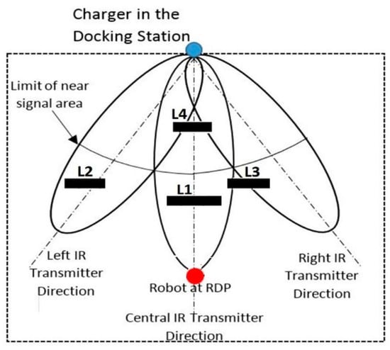
Figure 1.
A four-wheeled mobile robot (4-WMR), charger and the four landmarks in the experiment docking space.
The role of these landmarks (L1, L2, L3 and L4) was twofold in this test space. First, they were used as references for the sensor measurement RPLIDAR-A3 scanner. Secondly, they interfered (to block) the broadcast IR signals from the charger to the robot. The robot departure position (RDP) was defined as the experiment starting position. From this RDP, the robot ran Algorithm 1 until finishing its docking operation. In addition to its infrared receiver (IRR), the robot was equipped with two encoders and one IMU module (smartphone-based sensor model) to provide Odometer and INS navigation data, respectively. These odometers provided wheel rotation rates, while the INS through the smartphone provided the acceleration force and the angular velocity to determine the robot’s orientation.
| Algorithm 1. Working principle of Odom-NIRNA |
| Input: IR signals, direction, for initial heading |
| Output: (xR, yR, R), CFlag Robot well docked to the charger |
| 1: repeat |
| 2: Call Algorithm 2 |
| 3: Calculate robot pose |
| 4: Update Robot pose to by using Equation (2) |
| 5: Move forward at more 1 m |
| 6: if Robot not well connected then |
| 7: goto line 2 |
| 8: else the Robot reaches the goal |
| 9: CFlag = True |
| 8: return (xR, yR, R), CFlag |
| 9: end if |
| 10: until the Robot reaches the goal (End of Docking process) |
The robot (4-WMR), using its IRR, followed the received IR signals to dock to the charger in the docking station. In addition, its RPLIDAR-A3 scanner was implemented to get the observation data of the robot. Below, Table 1 presents the main specifications of the 4-WMR used, and some of its experimentation steps are illustrated in the Figure 2, Figure 3, Figure 4 and Figure 5.

Table 1.
4-WMR model parameters.
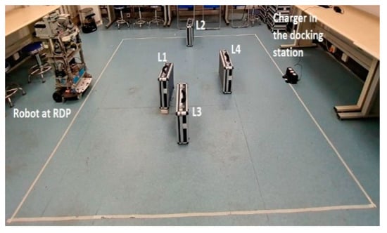
Figure 2.
4-WMR at the robot departure position (RDP).
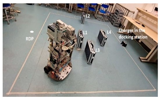
Figure 3.
4-WMR after turned 45° and moved forward 1.24 m.
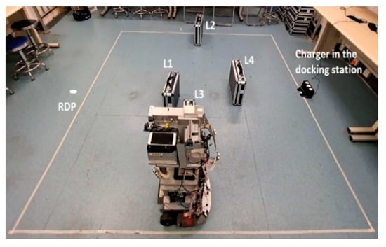
Figure 4.
4-WMR receiving only the right infrared transmitter (IRT) and traveling 2.08 m.
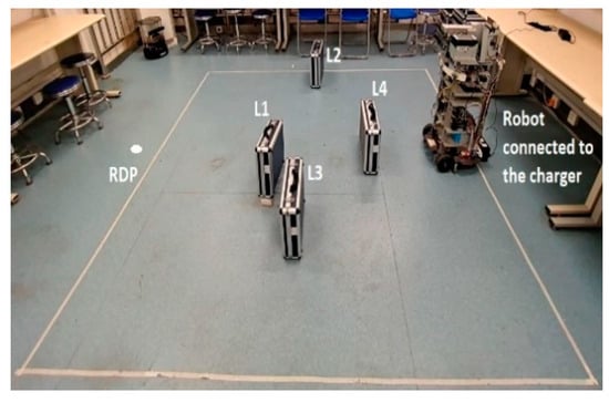
Figure 5.
4-WMR connected to the charger.
2.2. Experiment Parameters and Performance Measurements
The performance criterion was to determine the effect of NIRNA on the odometry localization approach used in this research. This was done by experimenting with our built system to identify the smallest pose errors of the robot. Recall that HIRNAH is a system based on an improved implementation of the classical UKF. This improvement came from the input data into the SFM, which in turn was based on the effect of NIRNA in the Odom-NIRNA navigation system. To realize this, the RDP was placed at 3.25 m from the charger on the main transmission line of the central IRT. In each experiment, the robot’s linear speed parameters (minimum and maximum) were set to be 0.01 m/s and 0.05 m/s respectively, and its angular velocities (minimum and maximum) were set to be 0.1 rad/s and 0.66 rad/s respectively, as indicated in Table 1 above.
To determine accurate measurements of the robot’s final pose, pose errors were defined and used as measurement units in this experiment. Pose errors for each run were defined to be the absolute values of the differences between the actual pose and the calculated pose for each performance measurement (HIRNAH, hardware and control technology navigation (HCTNav), rapid exploring random tree (RRT) [] and INS(IMU)), defined in Table 2 below. For each performance measurement, ten experiments were conducted.
Table 2.
The definitions of the performance measurements.
3. Comparison Analysis and Statistical Evaluation of the Results
The produced errors of the position and orientation are presented in Figure 6 and Figure 7, while the statistical analysis based on mean square error (MSE) are presented in Table 3 below.
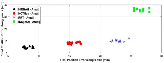
Figure 6.
Robot’s final position for ten runs.
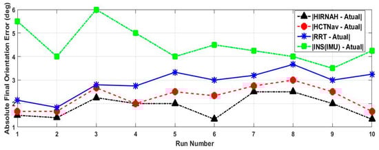
Figure 7.
Robot’s final orientation error.
Table 3.
The mean square errors (MSEs) (mm) over 10 runs. Errors stated with respect to the true robot’s state (position (x, y) and orientation ( )).
In these experimentation tests, the robot’s travel path consisted of reaching the charger from the RDP by implementing successively the system based on NIRNA, HCTNav, RRT and INS (IMU) and then comparing the results. Implementing the system based on NIRNA, HCTNav or RRT consisted of successfully using as a navigation algorithm in the Odom-NIRNA module (see Figure 8) NIRNA, HCTNav or RRT. While implementing INS (IMU), the system was helped by camera data for navigation. The robot at the RDP facing the charger began to find the shortest path to the charger using the system.
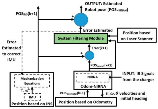
Figure 8.
The block scheme of the hierarchical infrared navigational algorithm hybridization (HIRNAH) architecture.
From Figure 6 and Figure 7 and Table 3, one can see that HIRNAH (the system when using NIRNA) provided more accurate positions and orientations, which was better than the system results when HCTNav, RRT or INS (IMU) were considered. In Figure 6, ten runs in each performance measurement of the robot’s final poses are shown. In this figure, HIRNAH was the best with the lowest errors on average along the x-axis (8.22 mm) and along the y-axis (4.64 mm), followed successively by HCTNav and RRT. For HCTNav, the average errors along the x-axis and y-axis were 15.60 mm and 8.31 mm, respectively. That was slightly better than those of RRT, which were 23.02 mm and 10.20 mm, respectively. Finally, the worst-case performance measurement was given by INS(IMU), with the more erroneous information, on average, 26.55 mm errors along the x-axis and 35.8 mm errors along the y-axis. In Figure 7, one can notice that HIRNAH presents the best performance measurement (in terms of the robot’s orientation errors for ten runs) with the lowest curve, followed successively by the curves for HCTNav, RRT and INS (IMU).
Throughout the ten experimental runs, HIRNAH provided less errors than the other performance measurements, except in run number four, where HIRNAH and HCTNav had the same errors. This is an exception which doesn’t appear often; otherwise (if it appears several times) it means the above supremacy of HIRNAH can be reversed under some conditions. Finally, the worst-case orientation errors of the robot were provided when the system used INS (IMU) in standalone mode.
Moreover, a statistical analysis based on the mean square error (MSE) metric was also done to evaluate the performance of our proposed method. The MSE values for the different estimation methods used are summarized in Table 3. Recall that a low MSE implies high confidence for the localization and states estimation methods. From these results in Table 3, the proposed HIRNAH method presents the most accurate results when compared with the others (HCTNav, RRT and INS (IMU)) used in this research. The large values of the MSE for INS (IMU) were due to its accumulated drifts during a long period of operation in the computation of the state variables. When HCTNav is considered, low MSE values were provided, compared with those of RRT and INS (IMU). This describes the effectiveness of this navigation algorithm. For RRT, the random choice of the next node made it perform worse, with somewhat high MSE values. Finally, HIRNAH provided smaller (and therefore more precise) values in terms of MSE along the three parameters of the robot state variables, thanks to the low noise associated with the robot’s pose when using NIRNA and given the history of measurements that can affect the accuracy of the robot’s state. Therefore, the proposed HIRNAH method, which uses a filtering technique and NIRNA, can significantly reduce the MSE of the robot state.
5. Conclusions
A new HIRNAH system for mobile robot state estimation and localization has been constructed in this research paper. Based on sensor fusion through a tight hybridization technique, the built system contains three hierarchical levels. Two navigation systems (Odometer and INS) and a sensor measurement module (an RPLIDAR-A3 scanner) cooperated to achieve this HIRNAH system. The information from the two navigation systems (INS(IMU) and Odom-NIRNA) are used to estimate the robot’s state errors. These errors are entered into the SFM with the sensor measurement (RPLIDAR-A3 scanner) data to produce estimated errors and smooth the robot pose provided by the INS(IMU) system in order to produce the robot’s final pose of the entire system. The Odom-NIRNA system is built based on integrating a new navigation algorithm NIRNA and odometry to improve the classical odometry navigation data.
In this research, simulations were conducted in order to validate the applicability of the proposed system. Based on the results from these simulations, a real system was built and used to experiment on a real robot in our laboratory. The experiment results show that HIRNAH outperforms all the performance measurements used in this research, such as HCTNav, RRT and INS(IMU). This means that the odometry integrated with NIRNA can be used to provide a more accurate estimation of the location information (position and orientation) for a 4-WMR.
In our future work, we plan to improve the proposed method by taking into account another scenario, including more landmarks and some dynamic objects. In addition, as we only tested the proposed method on a robot using a single IRR, there is further need to extend the number of IRRs to three (left IRR, central IRR and right IRR) and perform more evaluations of our built HIRNAH system. Another extension possibility will be to increase the number of runs in the experiments to at least a hundred times, and perhaps with other filtering techniques.
Author Contributions
Conceptualization, M.D.; data curation, M.D.; formal analysis, M.D.; funding acquisition, X.C.; investigation, M.D. and X.C.; methodology, M.D.; project administration, M.D.; resources, M.D. and X.C.; software, M.D.; supervision, X.C.; validation, M.D. and X.C.; visualization, X.C.; writing—original draft, M.D.; writing—review and editing, M.D. All authors have read and agreed to the published version of the manuscript.
Funding
This research was funded by The National Natural Science Foundation of China NSFC, grant number 61772185, and the APC was funded by the NSFC.
Conflicts of Interest
The authors declare no conflict of interest.
References
- Gupta, N.; Khosravy, M.; Patel, N.; Dey, N.; Gupta, S.; Darbari, H.; Crespo, R.G. Economic data analytic AI technique on IoT edge devices for health monitoring of agriculture machines. Appl. Intell. 2020, 50, 3990–4016. [Google Scholar] [CrossRef]
- Gupta, N.; Khosravy, M.; Gupta, S.; Dey, N.; Crespo, R.G. Lightweight artificial intelligence technology for health diagnosis of agriculture vehicles. Int. J. Parallel Program. 2020, 1–22. [Google Scholar] [CrossRef]
- Gupta, N.; Gupta, S.; Khosravy, M.; Dey, N.; Joshi, N.; Crespo, R.G.; Patel, N. Economic IoT strategy: The future technology for health monitoring and diagnostic of agriculture vehicles. J. Intell. Manuf. 2020, 1–12. [Google Scholar] [CrossRef]
- Al–Jarrah, R.; Shahzad, A.; Roth, H. Path planning and motion coordination for multi-robots system using probabilistic neuro–fuzzy. IFAC Pap. Online 2015, 48, 6–51. [Google Scholar] [CrossRef]
- Chi, W.; Wang, J.; Meng, M.Q. Risk-Informed-RRT*: A sampling-based human-friendly motion planning algorithm for mobile service robots in indoor environments. In Proceedings of the IEEE International Conference on Information and Automation (ICIA), Wuyishan, China, 11–13 August 2018; pp. 1101–1106. [Google Scholar]
- Hossain, M.A.; Ferdousand, I. Autonomous robot path planning in dynamic environment using a new optimization technique inspired by bacterial foraging technique. Robot. Auton. Syst. 2015, 64, 137–141. [Google Scholar] [CrossRef]
- Soragna, A.; Baldini, M.; Joho, D.; Kümmerle, R.; Grisetti, G. Active SLAM using connectivity graphs as priors. In Proceedings of the IEEE/RSJ International Conference on Intelligent Robots and Systems (IROS), Macau, China, 3–8 November 2019; pp. 340–346. [Google Scholar] [CrossRef]
- Trimble, J.; Pack, D.; Ruble, Z. Connectivity tracking methods for a network of unmanned aerial vehicles. In Proceedings of the IEEE 9th Annual Computing and Communication Workshop and Conference (CCWC), Las Vegas, NV, USA, 7–9 January 2019; pp. 440–447. [Google Scholar] [CrossRef]
- Zhang, C.; Chu, D.; Liu, S.; Deng, Z.; Wu, C.; Su, X. Trajectory planning and tracking for autonomous vehicle based on state lattice and model predictive control. IEEE Intell. Transp. Syst. Mag. 2019, 11, 29–40. [Google Scholar] [CrossRef]
- Zeng, D.; Yu, Z.; Xiong, L.; Fu, Z.; Zhang, P.; Zhou, H. $ DBO $ trajectory planning and $ HAHP $ decision-making for autonomous vehicle driving on urban environment. IEEE Access 2019, 7, 165365–165386. [Google Scholar] [CrossRef]
- Gao, K.; Xin, J.; Cheng, H.; Liu, D.; Li, J. Multi-mobile robot autonomous navigation system for intelligent logistics. In Proceedings of the Chinese Automation Congress (CAC), Xi’an, China, 30 November–2 December 2018; pp. 2603–2609. [Google Scholar] [CrossRef]
- Almeida, H.P.; Júnior, C.L.N.; Santos, D.D.S.; Leles, M.C.R. Autonomous navigation of a small-scale ground vehicle using low-cost IMU/GPS integration for outdoor applications. In Proceedings of the IEEE International Systems Conference (SysCon), Orlando, FL, USA, 8–11 April 2019; pp. 1–8. [Google Scholar] [CrossRef]
- Kanayama, H.; Ueda, T.; Ito, H.; Yamamoto, K. Two-mode mapless visual navigation of indoor autonomous mobile robot using deep convolutional neural network. In Proceedings of the IEEE/SICE International Symposium on System Integration (SII), Honolulu, HI, USA, 12–15 January 2020; pp. 536–541. [Google Scholar] [CrossRef]
- Li, Z.; Xiong, Y.; Zhou, L. ROS-based indoor autonomous exploration and navigation wheelchair. In Proceedings of the 10th International Symposium on Computational Intelligence and Design (ISCID), Hangzhou, China, 9–10 December 2017; pp. 132–135. [Google Scholar] [CrossRef]
- Li, J.M.; Chen, C.W.; Cheng, T.H. Estimation and tracking of a moving target by unmanned aerial vehicles. In Proceedings of the American Control Conference (ACC), Philadelphia, PA, USA, 10–12 July 2019; pp. 3944–3949. [Google Scholar] [CrossRef]
- Magrin, C.E.; Todt, E. Multi-sensor fusion method based on artificial neural network for mobile robot self-localization. In Proceedings of the Latin American Robotics Symposium (LARS), 2019 Brazilian Symposium on Robotics (SBR) and 2019 Workshop on Robotics in Education (WRE), Rio Grande, Brazil, 23–25 October 2019; pp. 138–143. [Google Scholar] [CrossRef]
- Ruan, X.; Liu, S.; Ren, D.; Zhu, X. Accurate 2D localization for mobile robot by multi-sensor fusion. In Proceedings of the IEEE 4th Information Technology and Mechatronics Engineering Conference (ITOEC), Chongqing, China, 14–16 December 2018; pp. 839–843. [Google Scholar] [CrossRef]
- Erfani, S.; Jafari, A.; Hajiahmad, A. Comparison of two data fusion methods for localization of wheeled mobile robot in farm conditions. Artif. Intell. Agric. 2019, 1, 48–55. [Google Scholar] [CrossRef]
- Al Khatib, E.I.; Jaradat, M.A.; Abdel-Hafez, M.; Roigari, M. Multiple sensor fusion for mobile robot localization and navigation using the extended Kalman filter. In Proceedings of the 10th International Symposium on Mechatronics and its Applications (ISMA), Sharjah, UAE, 8–10 December 2015; pp. 1–5. [Google Scholar] [CrossRef]
- Ullah, I.; Su, X.; Zhang, X.; Choi, D. Simultaneous localization and mapping based on Kalman filter and extended Kalman filter. Wirel. Commun. Mob. Comput. 2020, 2020, 2138643. [Google Scholar] [CrossRef]
- Debeunne, C.; Vivet, D. A review of visual-LiDAR fusion based simultaneous localization and mapping. Sensors 2020, 20, 2068. [Google Scholar] [CrossRef] [PubMed]
- Varghese, A.M.; Jisha, V.R. Motion planning and control of an autonomous mobile robot. In Proceedings of the International CET Conference on Control, Communication, and Computing 0, Thiruvananthapuram, India, 5–7 July 2018. [Google Scholar]
- Doumbia, M.; Cheng, X.; Chen, L. A novel infrared navigational algorithm for autonomous robots. In Proceedings of the IEEE International Conference on Artificial Intelligence and Information Systems, Dalian, China, 20–22 March 2020. [Google Scholar]
- Parween, R.; Heredia, M.V.; Rayguru, M.M.; Abdulkader, R.E.; Elara, M.R. Autonomous self-reconfigurable floor cleaning robot. IEEE Access 2020, 8, 114433–114442. [Google Scholar] [CrossRef]
- Shahian Jahromi, B.; Tulabandhula, T.; Cetin, S. Real-time hybrid multi-sensor fusion framework for perception in autonomous vehicles. Sensors 2019, 19, 4357. [Google Scholar] [CrossRef] [PubMed]
- De Silva, V.; Roche, J.; Kondoz, A. Robust fusion of LiDAR and wide-angle camera data for autonomous mobile robots. Sensors 2018, 18, 2730. [Google Scholar] [CrossRef] [PubMed]
- Nada, D.; Bousbia-Salah, M.; Bettayeb, M. Multi-sensor data fusion for wheelchair position estimation with unscented Kalman Filter. Int. J. Autom. Comput. 2018, 15, 207–217. [Google Scholar] [CrossRef]
- Li, K.; Xu, Y.; Wang, J.; Meng, M.Q.H. SARL: Deep reinforcement learning based human-aware navigation for mobile robot in indoor environments. In Proceedings of the 2019 IEEE International Conference on Robotics and Biomimetics (ROBIO), Dali, China, 6–8 December 2019; pp. 688–694. [Google Scholar] [CrossRef]
- Surmann, H.; Jestel, C.; Marchel, R.; Musberg, F.; Elhadj, H.; Ardani, M. Deep Reinforcement Learning for Real Autonomous Mobile Robot Navigation in Indoor Environments. Available online: https://arxiv.org/abs/2005.13857 (accessed on 14 October 2020).
- Amjad, H.; Sultan, M.; Khan, H.R. Low cost 2D RPLIDAR scanner based indoor mapping and classification system. In Proceedings of the 2019 International Conference on Robotics and Automation in Industry (ICRAI), Rawalpindi, Pakistan, 21–22 October 2019; pp. 1–6. [Google Scholar] [CrossRef]
Publisher’s Note: MDPI stays neutral with regard to jurisdictional claims in published maps and institutional affiliations. |
© 2020 by the authors. Licensee MDPI, Basel, Switzerland. This article is an open access article distributed under the terms and conditions of the Creative Commons Attribution (CC BY) license (http://creativecommons.org/licenses/by/4.0/).