Article

Theoretical Study on Transverse Mode Instability in Raman Fiber Amplifiers Considering Mode Excitation

1
College of Advanced Interdisciplinary Studies, National University of Defense Technology, Changsha 410073, China
2
Nanhu Laser Laboratory, National University of Defense Technology, Changsha 410073, China
3
Hunan Provincial Key Laboratory of High Energy Laser Technology, Changsha 410073, China
*
Authors to whom correspondence should be addressed.
Micromachines 2024, 15(10), 1237; https://doi.org/10.3390/mi15101237
Submission received: 27 August 2024 / Revised: 1 October 2024 / Accepted: 4 October 2024 / Published: 7 October 2024
(This article belongs to the Special Issue High Power Fiber Laser Technology)

Abstract

:
Raman fiber lasers (RFLs), which are based on the stimulated Raman scattering effect, generate laser beams and offer distinct advantages such as flexibility in wavelength, low quantum defects, and absence from photo-darkening. However, as the power of the RFLs increases, heat generation emerges as a critical constraint on further power scaling. This escalating thermal load might result in transverse mode instability (TMI), thereby posing a significant challenge to the development of RFLs. In this work, a static model of the TMI effect in a high-power Raman fiber amplifier based on stimulated thermal Rayleigh scattering is established considering higher-order mode excitation. The variations of TMI threshold power with different seed power levels, fundamental mode purities, higher-order mode losses, and fiber lengths are investigated, while a TMI threshold formula with fundamental mode pumping is derived. This work will enrich the theoretical model of TMI and extend its application scope in TMI mitigation strategies, providing guidance for understanding and suppressing TMI in the RFLs.

1. Introduction

Raman fiber lasers (RFLs) capitalize on the stimulated Raman scattering (SRS) to achieve laser gain, demonstrating unique potential for the generation of high-power laser output [1,2,3]. The fibers used in RFLs do not necessitate rare-earth (RE) ion doping, thus eliminating the need for specific pump wavelength requirements [4,5,6]. Moreover, with the capability for cascaded operation, RFLs are able to provide laser output at wavelengths that are inaccessible to RE-doped lasers [7,8,9,10,11]. Additionally, RFLs are resistant to challenges such as gain saturation, amplified spontaneous emission, and photon darkening—issues that are critical in the development of high-power RE-doped fiber lasers [12,13]. To date, RFLs have successfully achieved multi-kilowatt laser outputs, with Yb-Raman hybrid gain lasers notably reaching the 10-kW level [14], thereby broadening their applicability in practical scenarios.
At the kilowatt level, Xiao et al. conducted measurements of the beam quality of Yb-Raman hybrid gain lasers across various power levels [15]. Their findings revealed a distinct threshold phenomenon, characterized by a rapid increase in the M2 factor from below 1.35 to approximately 1.5. Similarly, certain fiber lasers utilizing pure Raman gain exhibited inferior beam quality, with M2 factors degrading to 2.5 [16,17]. These declines in beam quality are likely attributable to mode instability, which may pose a significant challenge to the advancement of high-power RFLs.
In the field of high-power fiber laser technology, the phenomenon of transverse mode instability (TMI), which is a consequence of thermo-optic and nonlinearity effects, has been extensively investigated in ytterbium-doped fiber lasers (YDFLs) [18,19,20,21,22,23,24,25,26,27,28]. However, theoretical and experimental research about TMI of RFLs remains relatively sparse. Distler et al. have explored the effects of varying seed power and fiber lengths on the TMI threshold, albeit within a limited range of parameters [29,30]. Naderi et al. established the first TMI model for Raman gain in Raman fiber amplifiers (RFA), although this model did not take fiber loss into account [31]. Dong subsequently developed a TMI model that incorporates both Raman gain and Yb-Raman hybrid gain in RFA [32], incorporating fiber loss and analyzing the impact of various parameters on the TMI effect, thereby enriching the theoretical model of TMI in RFA. However, these two models mainly focus on passive suppression strategies. In YDFLs, the TMI effect can be suppressed by actively controlling the mode in the fiber. In 2023, Chen et al. proposed a method to mitigate TMI by exciting higher-order modes within the ytterbium-doped fiber amplifier. Their findings indicated that the TMI threshold power increases linearly with the number of similarly excited modes [33]. However, due to the differing gain mechanisms, employing mode-controlled fiber lasers as seed and pump sources in RFA increases the modal count, which could potentially degrade beam quality. Therefore, there is a pressing need to develop a theoretical model that investigates the impact of modal purity on the TMI threshold power in RFA.
In this work, we introduced a higher-order mode (LP11) that is incoherent with LP01 and simulated the impact of seed and pump purities on the TMI threshold. A static TMI model of RFA, based on stimulated thermal Rayleigh scattering, is established. Additionally, fiber losses and lengths are taken into account in this model. The simulation results indicate that the TMI threshold is influenced by the purities of both the seed and pump, where decreased seed purity and increased pump purity contribute to an increase in TMI threshold. The research findings provide valuable insights for enhancing the TMI threshold in RFA, offering a reference for achieving high-power, high-brightness laser output.

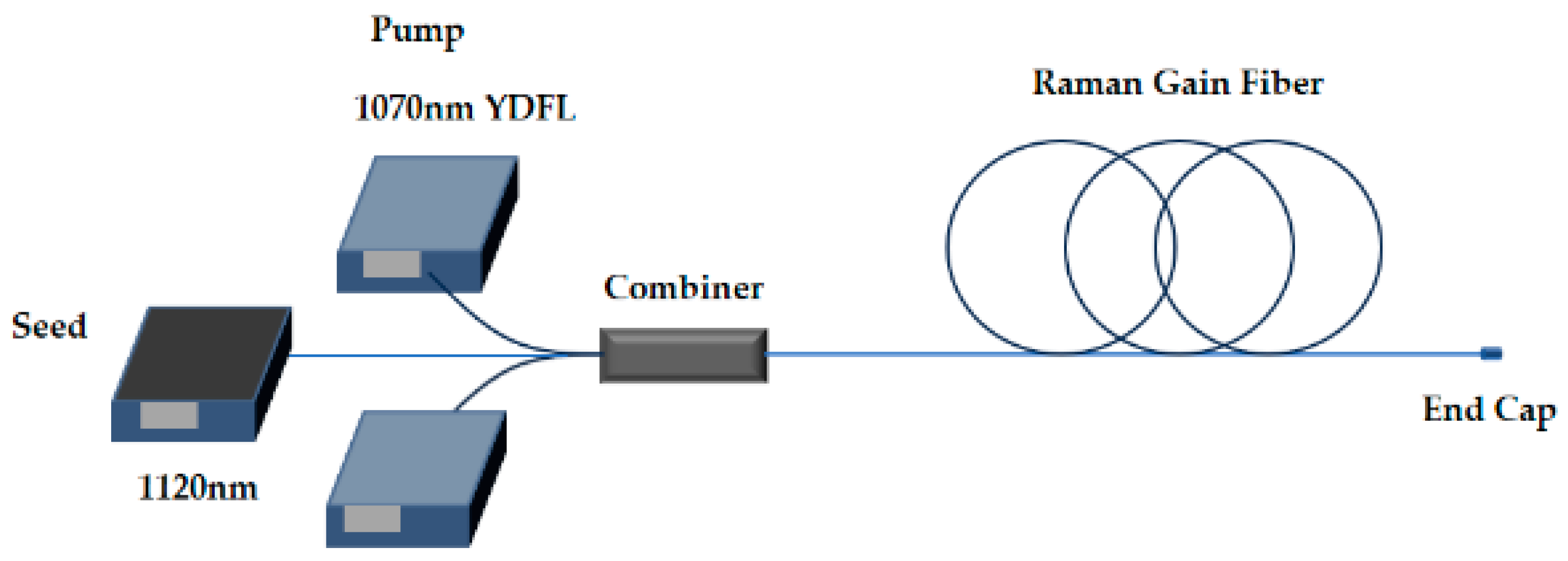
2. Theoretical Model

The RFA model uses a few-mode step-index fiber, which allows for the reasonable assumption that both the LP01 and LP11 modes are present within the system, consistent with most TMI models. It is assumed that the LP11 mode from the pump or seed is incoherent with the LP01 [34], while the Stokes frequency-shifted LP11 is due to quantum noise, and TMI is caused by the interaction between the LP01 and the Stokes frequency-shifted LP11 [33]. It is important to note that the model does not account for the effects of thermal lensing or the higher-order Raman frequency shift.
Firstly, we establish the power evolution model of RFA. In the case of only first-order Raman frequency shift and only LP01 and LP11 modes, the power evolution process is described by the following formula [35]:
d P P , m ( z ) d z = g P , m ( z ) P P , m ( z ) - α P , m ( z ) P P , m ( z ) , m = 1 , 2
d P S , m ( z ) d z = g S , m ( z ) P S , m ( z ) - α S , m ( z ) P S , m ( z ) , m = 1 , 2
where PP(S) is power of pump (signal); α is background loss; subscript m stands for different modes, where m = 1 means LP01 mode and m = 2 means LP11 mode; and gm is the Raman gain of the m-th mode. Equations (1) and (2) are initial value problems, given an initial seed and pump power (z = 0), the power at the fiber output (z = L, L is the fiber length) is obtained. Raman gain can be expressed in the following form:
g P , m ( z ) = - λ S λ P i = 1 2 g R ( λ P , λ S ) A e f f ( i , m ) ( λ P , λ S ) P S , i ( z ) , m = 1 , 2
g S , m ( z ) = i = 1 2 g R ( λ P , λ S ) A e f f ( i , m ) ( λ P , λ S ) P P , i ( z ) , m = 1 , 2
where gR(λp, λs) is the Raman gain coefficient of silica, whose value is approximately the order of 10−14; Aeff(i,m) is the effective interaction field area between mode i and mode m; and each mode corresponds to a signal and a pump. In the fiber we calculate that the Aeff between LP01 modes (~264 μm2) is smaller than that between LP01 mode and LP11 mode (~424 μm2). Therefore, in RFA, the gain of the signal is significantly influenced by the effective interaction field area. Aeff(i,m) is defined by the following [35]:
A e f f ( i , m ) = 0 R c l a d 0 2 π ψ P , i 2 r d ϕ d r 0 R c l a d 0 2 π ψ S , m 2 r d ϕ d r 0 R c l a d 0 2 π ψ P , i 2 ψ S , m 2 r d ϕ d r , i = 1 , 2   &   m = 1 , 2
where ψ is the normalized mode distribution; r and φ are radial coordinates and angular coordinates, respectively; and Rclad is the radius of the fiber cladding.
According to the RFA model described above, we can obtain the gain amplification process for both the fundamental mode and higher-order modes at the same frequency. Although the fundamental mode and higher-order modes at the same frequency can form a static long-period refractive index grating, the static grating does not cause dynamic mode coupling. Only the dynamic refractive index grating formed between the fundamental mode and higher-order modes with Stokes frequency shift can lead to dynamic mode coupling, resulting in the TMI phenomenon.
According to the thermo-optic effect, the dynamic thermally-induced refractive index grating generated by the inter-mode interference field between the LP01 mode and LP11 mode with the frequency shift Ω can be expressed as follows:
Δ n ( r , ϕ , z , t ) = k T T ( r , ϕ , z , t )
ρ C T r , ϕ , z , t t κ 2 T r , ϕ , z , t = Q r , ϕ , z , t
where kT is the thermo-optic coefficient; T is the temperature distribution; κ, ρ, and C are the thermal conductivity, density, and specific heat of silica, respectively; and Q is the heat density distribution generated by the interference field, which can be expressed as follows:
Q r , ϕ , z , t = q D g R I P ( r , ϕ , z ) A 1 ( z , t ) A S t o k e s * ( z , t ) ψ s , 1 ( r , ϕ ) ψ s , 2 ( r , ϕ ) e i ( Δ β z Ω t )
where q D = λ S / λ P 1 is the quantum defect of Raman conversion; A1 is the amplitude of LP01 mode; AStokes is the amplitude of LP11 mode with the frequency shift Ω; IP is the light intensity of pump; and Δβ is the difference of propagation constants between LP01 mode and LP11 mode. Using Green’s function method, the thermally induced refractive index change can be expressed as follows:
Δ n r , ϕ , z , t = k T v = 0 l = 1 J v ( k v l r ) 0 2 π 0 R c l a d q D g R I P ( r , ϕ , z ) A 1 ( z , t ) A S t o k e s * ( z , t ) ψ s , 1 ( r , ϕ ) ψ s , 2 ( r , ϕ ) r , ϕ , z , t J v ( k v l r ) cos [ v ( ϕ ϕ ) ] r d r d ϕ ( κ k v l 2 i Ω ρ C ) 0 2 π 0 R c l a d J v 2 ( k v l r ) cos 2 ( v ϕ ) r d r d ϕ e i ( Δ β z Ω t )
where kvl is the l-th positive root of the equation J v ( k v l r c l a d ) = 0 .
Based on the nonlinear propagation equation, 2 E n c 2 2 E t 2 = 1 ε 0 c 2 2 P N L t 2 , the nonlinear polarization intensity, P N L 2 n ε 0 E Δ n , the inter-mode coupling equations between the LP01 mode and LP11 mode with Stokes frequency shift can be rewritten as follows:
P S , 1 z = ( g S , 1 α S , 1 ) P S , 1 ( z ) g S , 1 χ P S , 1 ( z ) P S t o k e s ( z )
P S t o k e s z = ( g S , 2 α S , 2 ) P S t o k e s ( z ) g S , 1 χ P S , 1 ( z ) P S t o k e s ( z )
where PStokes is the LP11 mode power with the Stokes frequency shift. The nonlinear coupling coefficient χ is as follows:
χ = 2 k 0 Re 0 2 π 0 c l a d d i n g i Δ n A 1 ( z , t ) A S t o k e s ( z , t ) ψ 1 ( r , ϕ ) ψ 2 ( r , ϕ ) e i ( Δ β z Ω t ) r d r d g S , 1 P S , 1 ( z , t ) P S t o k e s ( z , t )
where k0 is the wave number and Re denotes taking the real part.
The total gain of mode LP11 mode with the frequency shift Ω is shown below:
G ( z , Ω ) = g 1 ( z ) χ ( Ω ) P 1 ( z ) + g S , 2 ( z ) α S , 2 ( z )
Thus, the power of Stokes frequency-shifted LP11 can be expressed as follows:
P S t o k e s ( z , Ω ) = P S t o k e s ( 0 ) exp [ 0 z G ( z , Ω ) d z ]
In the simulation, the power ratio of the Stokes frequency-shifted LP11 mode to signal LP01, denoted as ξ z = P S t o k e s z / P S , 1 z to characterize the TMI effect. When the ratio ξ(L) equal to 0.05, defined TMI occurs, the total signal output power is defined as TMI Threshold.

3. Results and Discussion

The purity is defined by the fundamental mode content, specifically the ratio of the power of LP01 to the total signal or pump power. It should be noted that the purity, whether pumped or seeded, ranges from 0.6 to 1. The simulation structure is shown in Figure 1, where the pump and signal are injected into the Raman gain fiber through the combiner and output through the end cap. The initial Stokes frequency-shifted LP11 power is set to 10−9 of the initial LP01 power, which is consistent with ref. [32]. Other parameters in the model are listed in Table 1.

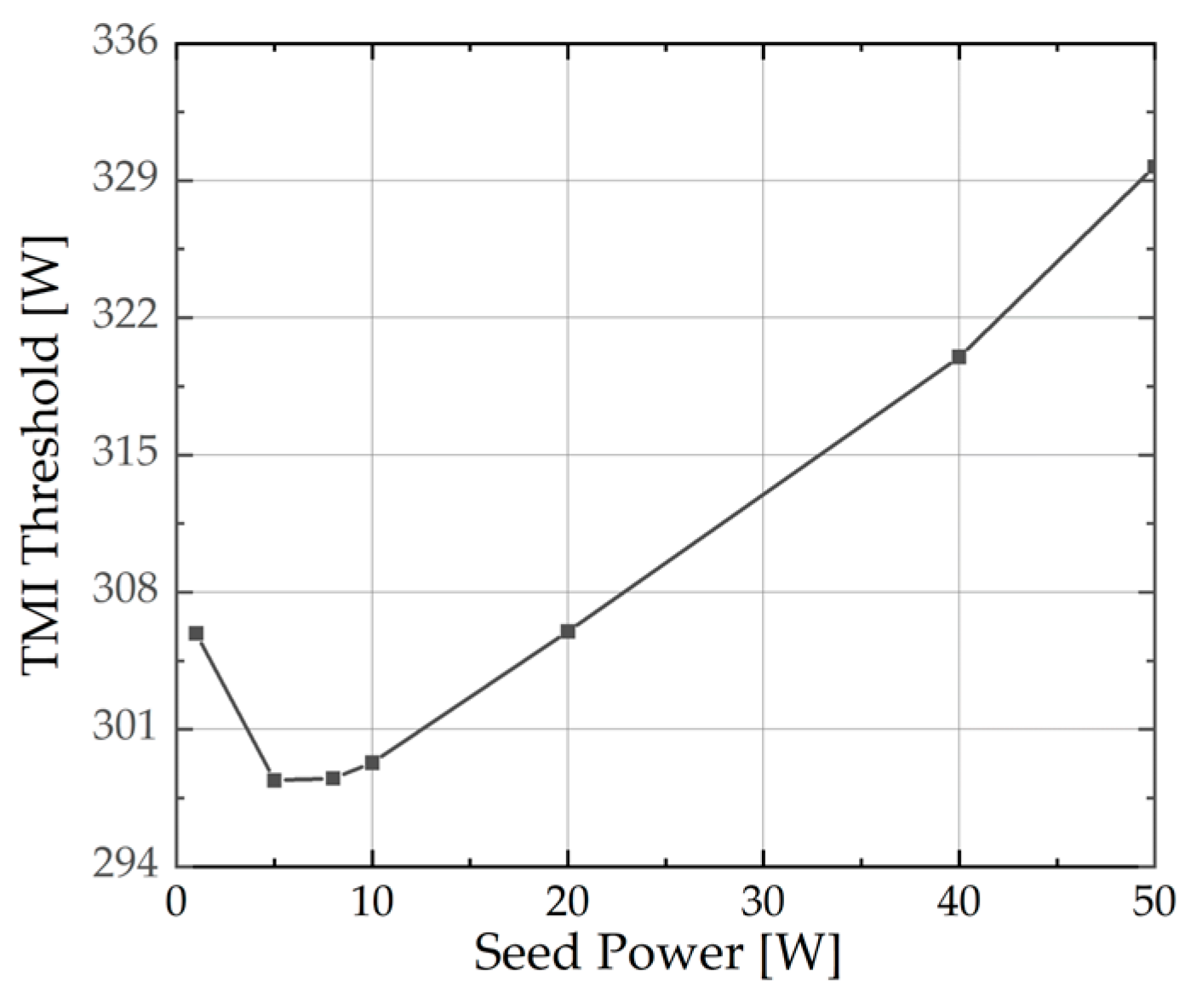
3.1. The TMI Threshold Changes with the Seed When the Pump Purity Is 1.0

In this section, it is assumed that the purity of the pump is 1.0, which corresponds to the case of pure LP01 mode pumping. From Equations (9) and (12), it can be observed that when the pump exists only LP01, the nonlinear coupling coefficient can be approximated as a constant. Therefore, regardless of loss, the output power of the signal LP01 can be expressed as follows:
P S , 1 ( L ) M χ ln P S , 1 ( L ) = ln ξ ( L ) / ξ ( 0 ) χ + P S , 1 ( 0 ) M χ ln P S , 1 ( 0 )
M = 1 A e f f ( 1 , 1 ) A e f f ( 1 , 2 )
It can be seen from Equation (15) that when TMI occurs, if the power of LP01 in the seed is fixed, the power of LP01 at output is also fixed. However, the output power of the LP01 does not vary linearly with the change in the LP01 power in seed.
According to Equation (2), the relationship between the signal LP11 output power and the power of the LP01 in seed is given by the following:
P S , 2 ( L ) = P S , 1 ( 0 ) e M 1 p u r i t y 1
The purity here refers to the seed purity. Based on Equations (15)–(17), two conclusions can be drawn: Firstly, when the power of the LP01 in the seed is fixed, the output signal LP01 power remains constant. As the seed purity decreases, the incoherent LP11 power increases, resulting in an increase in the TMI threshold. Secondly, with the seed power held constant, an increase in seed purity leads to a reduction in the incoherent LP11 power of the output signal. The variation of the output LP01 power, however, does not exhibit a monotonic trend. Therefore, it is not possible to directly summarize the change in the TMI threshold. Simulations were performed to address these two scenarios, and the findings are presented in Figure 2. The fiber length used in the simulation is 20 m, and the fiber loss is ignored. Other parameters are consistent with Table 1.
Figure 2a shows the change of TMI threshold and output signal LP01 power with different seed purities when LP01 power in the seed is 5 W. The LP01 power in the output signal is maintained at 299 W, while the TMI threshold increases as the seed purity decreases. When the seed purity is 0.6, the TMI threshold increases to 336 W. The simulation results demonstrate that a decrease in seed purity leads to an increase in the TMI threshold. This is because the occurrence of TMI is related to the power of LP01. Consequently, with equal LP01 power, an increase in the LP11 power within the seed leads to an increased TMI threshold.
The change in TMI threshold and output signal LP01 power with varying seed purities is illustrated in Figure 2b, while keeping the seed power fixed at 50 W. As the seed purity increases, both the TMI threshold and LP11 power of the output signal exhibit a monotonic trend. The TMI threshold was 330 W when the seed purity was 1.0. However, by reducing the seed purity to 0.6, the TMI threshold increases to 392 W.
When the seed purity is 1.0, the TMI threshold is higher at 50 W seed power, compared to the case at 5 W. To further investigate the impact of seed power on the TMI threshold, simulations were conducted with a seed purity of 1 at various seed power levels, while all other conditions remained constant. The results are depicted in Figure 3. As illustrated, the TMI threshold first decreases and then increases, reaching its minimum at a seed power of 8 W. By comparing the trends of the LP01 power in Figure 3 and Figure 2b, it is observed that if the LP01 power in the seed is equal, its output power is also equal. The simulation results are in accordance with our discussions regarding the Equations (15)–(17). The monotonic increase in LP01 power in Figure 2b may be attributed to its power variation range of 30 to 50 W. Within this range, as depicted in Figure 3, the power exhibits a consistent upward trend.
The TMI threshold of 50 W seed power reaches its maximum when the seed purity is 1.0. Therefore, in Section 3.2, the seed power of 50 W was used to study the effect of different pump purities on the TMI threshold in the case of seed purity equals to 1.0.

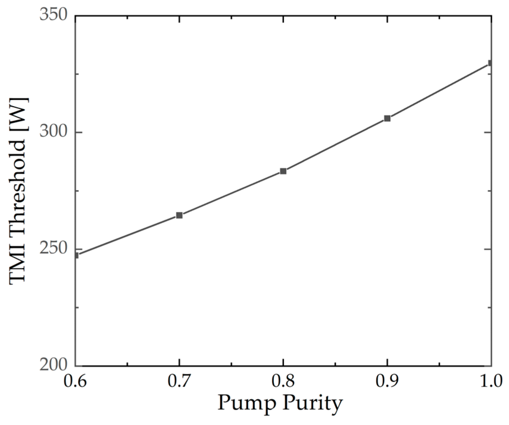
3.2. The TMI Threshold Changes with the Pump Purity When the Seed Purity Is 1.0

In Section 3.1, the impact of seed purity on the TMI threshold in RFA is discussed under the assumption of an ideal pumping purity of 1.0. Under core-pumped conditions, the presence of higher-order modes in the pumping can result in an enhancement of the Raman gain for the higher-order mode of the signal. The influence of pump purity on the TMI threshold will be discussed in this section.
Figure 4 shows the TMI threshold for different pump purities. The seed power is maintained at 50 W, and the seed purity is set to 1.0. Other parameters are consistent with Section 3.1. It is evident that the relationship between TMI threshold and pump purity is opposite to that between TMI threshold and seed purity. Specifically, the TMI threshold is observed to increase with pump purity; it increases from 247.3 W at a pump purity of 0.6 to 329.7 W at a pump purity of 1.0. In this theoretical model, the power of both the LP01 and the LP11 of the pump can be coupled to the Stokes frequency-shifted LP11 mode through Raman conversion. The Aeff between the LP11 modes is smaller than that between the LP11 and LP01. Consequently, at lower pump purity, the gain of the Stokes frequency-shifted LP11 is higher, resulting in a lower TMI threshold. Therefore, maintaining the high beam quality of the pump in experiments can lead to a higher TMI threshold.
According to Section 3.1 and the conclusions in this section, we can tentatively synthesize the impact of mode content on the TMI threshold. Combined with data corresponding to various seed and pump purities, utilizing a seed power of 50 W, as shown in Figure 5, while other parameters held constant as shown in Table 1. Figure 5a illustrates the variations in TMI threshold for different seed and pump purities. It is observed that as the seed purity decreases and the pump purity increases, there is a corresponding increase in the TMI threshold. Figure 5b shows the ratio of signal LP01 power to the total signal output power for different seed and pump purities. It can be observed that a higher purity of both the seed and pump leads to an increase in LP01 content. Therefore, in RFA, the purity of the pump should ideally be maintained as high as possible, while the purity of the seed should be adjusted according to the specific application scenarios to balance the high TMI threshold and the high LP01 content.

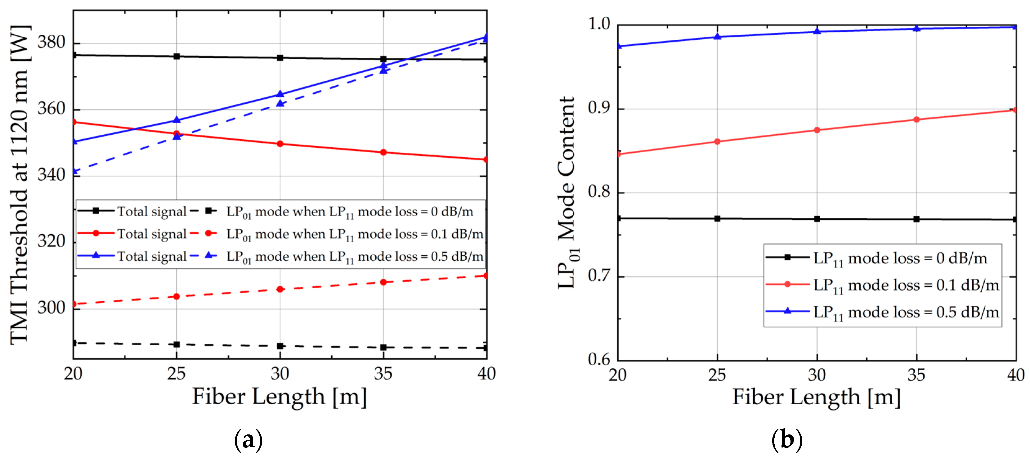
3.3. Influence of Fiber Length and Loss on TMI Threshold

The previous sections systematically analyzed the influence of mode excitation on the TMI threshold in RFA. This section will focus on strategies to increase the TMI threshold. Theoretically, the attenuation of higher-order modes significantly influences the TMI threshold. Consequently, Section 3.3.1 will investigate the impact of varying LP11 loss on the TMI threshold during the transmission process. Further, Section 3.3.2 will consider the LP11 loss to study the impact of different fiber lengths on the TMI threshold. Considering the results of the previous simulation, the seed purity is set to 0.6, the pump purity is set to 0.9, and the seed power is set to 50 W.

3.3.1. Influence of LP11 Mode Loss on TMI Threshold

In this subsection, the TMI threshold change under different LP11 losses is studied. For the convenience of analysis, the loss of the LP11 of both pump and seed (both are equal) will be changed while setting the attenuation of the LP01 to 0 dB/m, with all other parameters remaining unchanged as detailed in Table 1.
As shown in Figure 6, as the LP11 loss increases, the output signal power of LP01 increases linearly. In the case of low loss, the total output power of the signal decreases because the growth of the LP01 mode cannot compensate for the loss of the LP11 mode. This further affects the change of the TMI threshold.
The power evolution of Raman conversion is depicted in Figure 7a for the LP11 mode loss of 4.34 dB/m. Concurrently, the evolution and distribution of power for the Stokes frequency-shifted LP11 mode are illustrated in Figure 7b. As shown in Figure 7b, the power of Stokes frequency-shifted LP11 decreases initially due to the significant loss, which is the primary reason for the increase in the TMI threshold. According to Figure 7a, the signal output power is 626.3 W at the high LP11 mode loss. The purity of the fundamental mode approaches 1.0, the injection pump power reaches 913.4 W, and the Raman conversion efficiency is 63.1%. Therefore, during specific experiments, increasing the LP11 mode loss by bending the fiber or using functional passive fiber components [36] will increase the TMI threshold and increase the output signal fundamental mode content.

3.3.2. Influence of Fiber Length on TMI Threshold

In this subsection, the influence of fiber length on the TMI threshold is studied when the LP11 mode loss is 0, 0.1, and 0.5 dB/m, respectively. The LP01 loss is ignored, and other parameters remain consistent with Table 1. The results are shown in Figure 8.
As observed in Figure 8a, when there is no loss in the fiber, the TMI threshold appears to be largely independent of the fiber length. However, when considering LP11 loss, a greater loss results in a more rapid attenuation of the Stokes frequency-shifted LP11. This delays the emergence of the TMI effect, thereby improving the power of the LP01.

4. Conclusions

Considering mode excitation, a static model of TMI in RFA is established based on stimulated thermal Rayleigh scattering and power coupling theory in this work. Higher-order mode at the same frequency as fundamental mode in RFA is introduced, and the effect of different seed and pump purities on the TMI threshold is simulated. The simulation results indicate that the TMI threshold decreases with the increase in seed purity. And it first decreases and then increases with the increase in seed power. However, reducing the seed purity will decrease the output power of the LP01, which needs a trade-off in practical applications. Contrary to the effect of seed purity, an increase in pump purity is directly associated with an increased TMI threshold, implying that a high-brightness pump source is essential. The influence of LP11 losses and fiber lengths on the TMI threshold of RFA is essentially the influence on the frequency-shifted LP11 power. An increase in the loss of frequency-shifted LP11 corresponds to a reduction in the gain as described by Equation (13), consequently leading to an increased TMI threshold. The research findings provide new insights into enhancing the TMI threshold in RFA, offering a reference for achieving high-power, high-brightness laser output.

Author Contributions

Methodology, L.H.; validation, L.H. and T.Y.; investigation, S.H., X.H. and H.L.; data curation, S.H.; writing—original draft preparation, S.H., X.H. and H.L.; writing—review and editing, C.F., X.C., T.Y., L.H. and P.Z.; supervision, L.H.; project administration, L.H.; funding acquisition, T.Y. All authors have read and agreed to the published version of the manuscript.

Funding

This research was funded by the National Natural Science Foundation of China, grant No. 12174445.

Institutional Review Board Statement

Not applicable.

Informed Consent Statement

Not applicable.

Data Availability Statement

The data that support the findings of this study are available from the authors upon reasonable request.

Conflicts of Interest

The authors declare no conflicts of interest.

References

  1. Zhang, L.; Liu, C.; Jiang, H.; Qi, Y.; He, B.; Zhou, J.; Gu, X.; Feng, Y. Kilowatt Ytterbium-Raman fiber laser. Opt. Express 2014, 22, 18483–18489. [Google Scholar] [CrossRef] [PubMed]
  2. Hao, X.; Li, Y.; Fan, C.; Wu, J.; Pan, Z.; Leng, J.; Yao, T.; Lei, B.; Zhou, P. Kilowatt Raman fiber laser directly pumped by spectrally-combined diodes. J. Light. Technol. 2024, 42, 5349–5355. [Google Scholar] [CrossRef]
  3. Zhang, Y.; Xu, J.; Liang, J.; Li, S.; Ye, J.; Ma, X.; Yao, T.; Pan, Z.; Huang, L.; Leng, J.; et al. Triple-clad-fiber-based kilowatt-level tunable Raman laser. Opt. Laser Technol. 2024, 174, 110654. [Google Scholar] [CrossRef]
  4. Supradeepa, V.R.; Feng, Y.; Nicholson, J.W. Raman fiber lasers. J. Opt. 2017, 19, 023001. [Google Scholar] [CrossRef]
  5. Glick, Y.; Shamir, Y.; Sintov, Y.; Goldring, S.; Pearl, S. Brightness enhancement with Raman fiber lasers and amplifiers using multi-mode or multi-clad fibers. Opt. Fiber Technol. 2019, 52, 101955. [Google Scholar] [CrossRef]
  6. Sirleto, L.; Ferrara, M.A. Fiber Amplifiers and Fiber Lasers Based on Stimulated Raman Scattering: A Review. Micromachines 2020, 11, 247. [Google Scholar] [CrossRef]
  7. Choudhury, V.; Arun, S.; Prakash, R.; Supradeepa, V.R. High-power continuous-wave supercontinuum generation in highly nonlinear fibers pumped with high-order cascaded Raman fiber amplifiers. Appl. Opt. 2018, 57, 5978–5982. [Google Scholar] [CrossRef] [PubMed]
  8. Qi, W.; Zhou, J.; Cao, X.; Cheng, Z.; Jiang, H.; Cui, S.; Feng, Y. Cascaded nonlinear optical gain modulation for coherent femtosecond pulse generation. Opt. Express 2022, 30, 8889–8897. [Google Scholar] [CrossRef]
  9. Deheri, R.; Dash, S.; Supradeepa, V.R.; Balaswamy, V. Cascaded Raman fiber lasers with ultrahigh spectral purity. Opt. Lett. 2022, 47, 3499–3502. [Google Scholar] [CrossRef]
  10. Zhou, J.; Pan, W.; Qi, W.; Cao, X.; Cheng, Z.; Feng, Y. Ultrafast Raman fiber laser: A review and prospect. PhotoniX 2022, 3, 18. [Google Scholar] [CrossRef]
  11. Kuznetsov, A.G.; Kablukov, S.I.; Wolf, A.A.; Nemov, I.N.; Tyrtyshnyy, V.A.; Myasnikov, D.V.; Babin, S.A. 976 nm all-fiber Raman laser with high beam quality at multimode laser diode pumping. Laser Phys. Lett. 2019, 16, 105102. [Google Scholar] [CrossRef]
  12. Jauregui, C.; Limpert, J.; Tuennermann, A. High-power fibre lasers. Nat. Photonics 2013, 7, 861–867. [Google Scholar] [CrossRef]
  13. Codemard, C.A.; Dupriez, P.; Jeong, Y.; Sahu, J.K.; Ibsen, M.; Nilsson, J. High-power continuous-wave cladding-pumped Raman fiber laser. Opt. Lett. 2006, 31, 2290–2292. [Google Scholar] [CrossRef]
  14. Qi, T.; Li, D.; Fu, G.; Yang, Y.; Li, G.; Wang, L.; Du, S.; Yan, P.; Gong, M.; Xiao, Q. Amplification of random lasing enables a 10-kW-level high-spectral-purity Yb–Raman fiber laser. Opt. Lett. 2023, 48, 1794–1797. [Google Scholar] [CrossRef]
  15. Xiao, Q.; Yan, P.; Li, D.; Sun, J.; Wang, X.; Huang, Y.; Gong, M. Bidirectional pumped high power Raman fiber laser. Opt. Express 2016, 24, 6758–6768. [Google Scholar] [CrossRef]
  16. Glick, Y.; Shamir, Y.; Aviel, M.; Sintov, Y.; Goldring, S.; Shafir, N.; Pearl, S. 1.2 kW clad pumped Raman all-passive-fiber laser with brightness enhancement. Opt. Lett. 2018, 43, 4755–4758. [Google Scholar] [CrossRef]
  17. Chen, Y.; Yao, T.; Huang, L.; Xiao, H.; Leng, J.; Zhou, P. 2 kW high-efficiency Raman fiber amplifier based on passive fiber with dynamic analysis on beam cleanup and fluctuation. Opt. Express 2020, 28, 3495–3504. [Google Scholar] [CrossRef]
  18. Smith, A.V.; Smith, J.J. Mode instability in high power fiber amplifiers. Opt. Express 2011, 19, 10180–10192. [Google Scholar] [CrossRef]
  19. Jauregui, C.; Eidam, T.; Otto, H.-J.; Stutzki, F.; Jansen, F.; Limpert, J.; Tuennermann, A. Physical origin of mode instabilities in high-power fiber laser systems. Opt. Express 2012, 20, 12912–12925. [Google Scholar] [CrossRef] [PubMed]
  20. Naderi, S.; Dajani, I.; Madden, T.; Robin, C. Investigations of modal instabilities in fiber amplifiers through detailed numerical simulations. Opt. Express 2013, 21, 16111–16129. [Google Scholar] [CrossRef] [PubMed]
  21. Dong, L. Stimulated thermal Rayleigh scattering in optical fibers. Opt. Express 2013, 21, 2642–2656. [Google Scholar] [CrossRef] [PubMed]
  22. Smith, A.V.; Smith, J.J. Overview of a Steady-Periodic Model of Modal Instability in Fiber Amplifiers. IEEE J. Sel. Top. Quantum. Electron. 2014, 20, 472–483. [Google Scholar] [CrossRef]
  23. Hansen, K.R.; Laegsgaard, J. Impact of gain saturation on the mode instability threshold in high-power fiber amplifiers. Opt. Express 2014, 22, 11267–11278. [Google Scholar] [CrossRef]
  24. Li, Z.; Huang, Z.; Xiang, X.; Liang, X.; Lin, H.; Xu, S.; Yang, Z.; Wang, J.; Jing, F. Experimental demonstration of transverse mode instability enhancement by a counter-pumped scheme in a 2 kW all-fiberized laser. Photonics Res. 2017, 5, 77–81. [Google Scholar] [CrossRef]
  25. Menyuk, C.R.; Young, J.T.; Hu, J.; Goers, A.J.; Brown, D.M.; Dennis, M.L. Accurate and efficient modeling of the transverse mode instability in high energy laser amplifiers. Opt. Express 2021, 29, 17746–17757. [Google Scholar] [CrossRef]
  26. Li, R.; Li, H.; Wu, H.; Xiao, H.; Leng, J.; Huang, L.; Pan, Z.; Hou, P. Mitigation of TMI in an 8 kW tandem pumped fiber amplifier enabled by inter-mode gain competition mechanism through bending control. Opt. Express 2023, 31, 24423–24436. [Google Scholar] [CrossRef] [PubMed]
  27. Zervas, M.N. Transverse mode instability, thermal lensing and power scaling in Yb3+-doped high-power fiber amplifiers. Opt. Express 2019, 27, 19019–19041. [Google Scholar] [CrossRef]
  28. Dong, L.; Ballato, J.; Kolis, J. Power scaling limits of diffraction-limited fiber amplifiers considering transverse mode instability. Opt. Express 2023, 31, 6690–6703. [Google Scholar] [CrossRef]
  29. Distler, V.; Möller, F.; Strecker, M.; Palma-Vega, G.; Walbaum, T.; Schreiber, T. Transverse mode instability in a passive fiber induced by stimulated Raman scattering. Opt. Express 2020, 28, 22819–22828. [Google Scholar] [CrossRef]
  30. Distler, V.; Moeller, F.; Strecker, M.; Palma-Vega, G.; Walbaum, T.; Schreiber, T.; Tuennermann, A. High power narrow-linewidth Raman amplifier and its limitation. In Proceedings of the Fiber Lasers XVII: Technology and Systems, San Diego, CA, USA, 3–6 February 2020. [Google Scholar]
  31. Naderi, S.; Dajani, I.; Grosek, J.; Madden, T. Theoretical and numerical treatment of modal instability in high-power core and cladding-pumped Raman fiber amplifiers. Opt. Express 2016, 24, 16550–16565. [Google Scholar] [CrossRef]
  32. Dong, L. Transverse Mode Instability in Raman Fiber Amplifiers. IEEE J. Quantum Electron. 2023, 59, 1–8. [Google Scholar] [CrossRef]
  33. Chen, C.-W.; Wisal, K.; Eliezer, Y.; Stone, A.D.; Cao, H. Suppressing transverse mode instability through multimode excitation in a fiber amplifier. Proc. Natl. Acad. Sci. USA 2023, 120, e2217735120. [Google Scholar] [CrossRef]
  34. Chu, Q.; Tao, R.; Li, C.; Lin, H.; Wang, Y.; Guo, C.; Wang, J.; Jing, F.; Tang, C. Experimental study of the influence of mode excitation on mode instability in high power fiber amplifier. Sci. Rep. 2019, 9, 9396. [Google Scholar] [CrossRef]
  35. Zhu, S.; Pidishety, S.; Feng, Y.; Hong, S.; Demas, J.; Sidharthan, R.; Yoo, S.; Ramachandran, S.; Srinivasan, B.; Nilsson, J. Multimode-pumped Raman amplification of a higher order mode in a large mode area fiber. Opt. Express 2018, 26, 23295–23304. [Google Scholar] [CrossRef]
  36. Chen, X.; Yao, T.; Huang, L.; An, Y.; Wu, H.; Pan, Z.; Zhou, P. Functional Fibers and Functional Fiber-Based Components for High-Power Lasers. Adv. Fiber Mater. 2022, 5, 59–106. [Google Scholar] [CrossRef]
Figure 1. Schematic diagram of the RFA structure.
Micromachines 15 01237 g001
Figure 2. The change in TMI threshold and output signal LP01 power with varying seed purities. (a) When the LP01 power in seed is fixed at 5 W; (b) When the seed power is fixed at 50 W.
Micromachines 15 01237 g002
Figure 3. The TMI threshold under different seed power.
Micromachines 15 01237 g003
Figure 4. The TMI threshold under different pump purities.
Micromachines 15 01237 g004
Figure 5. (a) The TMI threshold and (b) the LP01 content varies with different seed and pump purities.
Micromachines 15 01237 g005
Figure 6. The pump power, total signal power, and LP01 power of the signal under different LP11 mode losses when TMI occurs.
Micromachines 15 01237 g006
Figure 7. (a) Power evolution in RFA; (b) Power evolution and proportion of Stokes frequency-shifted LP11 mode at different positions along the fiber under a LP11 mode loss of 4.34 dB/m.
Micromachines 15 01237 g007
Figure 8. (a) Total output signal power and LP01 power of different fiber lengths; (b) LP01 mode purity at TMI thresholds of different fiber lengths.
Micromachines 15 01237 g008
Table 1. The main simulation parameters of Raman fiber amplifiers.
ParameterValueParameterValue
λ P 1070 nm κ 1.38 W/(m·K)
λ S 1120 nm k T 1.2 × 10⁻⁵ K−1
n c o r e 1.4662 g R 7.3 × 10⁻¹⁴ m/W
n c l a d 1.465 ρ C 1.63 × 10⁶ J/(K·m3)
2 r c o r e 20 μm 2 r c l a d 130 μm
Disclaimer/Publisher’s Note: The statements, opinions and data contained in all publications are solely those of the individual author(s) and contributor(s) and not of MDPI and/or the editor(s). MDPI and/or the editor(s) disclaim responsibility for any injury to people or property resulting from any ideas, methods, instructions or products referred to in the content.

