Abstract
In this research a portable potentiostat was built for electrochemical sensing measurements with three electrodes, specifically SPCEs. The circuit uses a microcontroller as the main controller to manage all activities, starting from adjusting the input voltage for the SPCEs, setting measurement parameters, measuring the resulting current, displaying graphics on the touch screen, sending data to the computer via the USB port, and connecting to the SD card. Measurements and errors with cyclic voltammetry techniques have been compared with commercial potentiostats. The measurement results on a dummy circuit and commercial SPCEs have an accuracy of more than 90% compared to commercial potentiostats. In addition, measurement data can also be saved to an SD card in .CSV format for further purposes.
1. Introduction
Several studies on potentiostats have recently been carried out. Graphical reading of measurement results from the biosensor still uses other tools such as computers, laptops, or smartphones. Potentiostats are key devices in modern electrochemical research related to redox chemical reactions and other chemical phenomena. In this study, Arduino was used, which was designed for cyclic voltammetric characterization and used to study redox reactions that occur at the electrode-electrolyte interface. The design is simple, easy to operate, and has low cost and good performance. Graphical reading is done with the help of a computer via a USB connection [1,2]. Some potentiostats that use interfacing with computers are potentiostat/galvanostat for thin-film battery characterization [3], potentiostat for teaching electrochemistry and instrumentation [4], CheapStat: potentiostat for analytical and educational applications [5], DStat: potentiostat for electroanalysis and integration [6], potentiostat with two microprocessors for electrochemical biosensors [7], and potentiostat for electrochemical biosensing measurement system [8]. Apart from these, other potentiostat studies using a smartphone connection wirelessly for graph reading include wireless potentiostat for electrochemical detection [9], KAUSTat: wireless potentiostat for electrochemical measurements [10], wireless potentiostat for multivariate data processing [11], and potentiostat wireless for electrochemical biosensor for point-of-care diagnostics [12]. Apart from the studies above, there is also a patent on a portable potentiostat that uses a battery and has its own display, namely the Portable instrument for field ready electrochemical experimentation [13].
The aim of this research is to design and implement a potentiostat circuit that can capture redox reactions in a typical three-electrode electrochemical sensor measurement system, namely the Working Electrode (WE), Counter Electrode (CE), and Reference Electrode (RE). In this case the sensor used is based on a screen printed carbon electrode (SPCE). SPCE is a type of SPE which has many advantages, namely requiring few samples, relatively cheap, easy to carry, and easy to use [14]. The designed circuit can be used to detect small current changes in SPCE-based sensors. A comparison of several microcontroller-based potentiostats that have been made, including this research (UnpadStat), can be seen in Table 1. UnpadStat has several advantages, namely being portable because it uses a battery, having its own display for setting parameters, storing data on an SD card for further analysis, and it can be connected to a computer for more detailed observation of measurement data.

Table 1.
Comparison of the main features of the reported potentiostats.
2. UnpadStat Design
The complete block diagram of the circuit can be seen in Figure 1. The input section is an SPCE-based sensor, which is an important gate where electrochemical reactions occur. The output section is divided into three, namely touch screen (Nextion 5 inch), computer, and SD card, where each of these outputs has different parameters. The most important part is the STM32-based microcontroller which manages the supporting components such as the 16-bit digital to analog converter (DAC), amplifier, and 16-bit analog to digital converter (ADC).
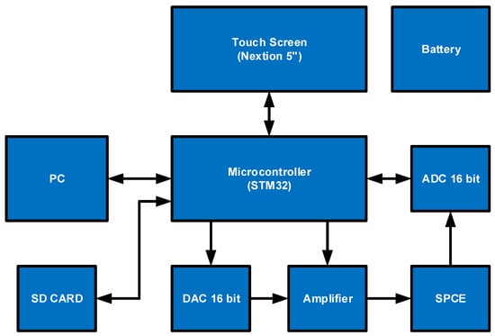
Figure 1.
UnpadStat block diagram.
The circuit design is divided into several parts to make it easier to analyze the potentiostat circuit.
- A.
- DAC
DAC serves to convert digital signals into analog signals or voltages. The DAC used here was an IC with the PCM56P type which is often used in audio. This IC has several advantages including stability, low noise, 16-bit resolution, small current, wide symmetrical supply voltage, and requires few additional components to work. The output voltage is also wide and can be adjusted from −3 V to +2.9999 V [15]. The output voltage regulation is carried out through three ports, namely the DATA, LE, and CLK ports. These three ports must be connected to the microcontroller. The complete DAC circuit can be seen in Figure 2A. Capacitors C1, C2, C3, and C4 are used to stabilize the voltage. Resistors R1, R2, and Potentiometer P1 are used to calibrate the output voltage.
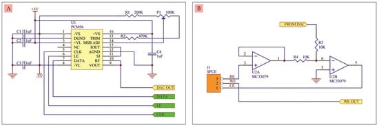
Figure 2.
(A) 16-bit DAC circuit, (B) Buffer and differential amplifier circuit.
- B.
- Buffer circuit and differential amplifier
The buffer circuit and differential amplifier were built from two op-amps of type MC33079. This IC has low noise, high frequency stability, wide symmetrical supply voltage, and small current [16]. The buffer circuit and differential amplifier can be seen in Figure 2B. The buffer circuit is needed so that the voltage generated by the Reference Electrode (RE) of the SPCE is stable and does not burden the SPCE. The voltage from the buffer is then compared with the voltage coming from the DAC using a differential amplifier circuit. The difference in voltage is fed back to the Counter Electrode (CE). By providing a voltage sweep on the DAC, it will produce a varying output current at the Working Electrode (WE).
- C.
- Current to voltage converter circuit
The circuit in Figure 3A was built from an MC33079 op-amp and an 8-channel electronic switch 74HC4051 [17]. MC33079 serves to convert the current coming out of the WE and into a voltage at the output of the op-amp. The voltage is directly proportional to the incoming current. Its voltage gain is determined by either resistors R5, R6, R7, R8, R9, or R10. The selection of resistors connected to the circuit is regulated by the IC 74HC4051 via the SA, SB, and SC ports. Meanwhile C5 serves to stabilize the voltage on the selected multiplier resistor. This resistor selection is useful for selecting a measurement scale ranging from tens of nano amperes to milli amperes.
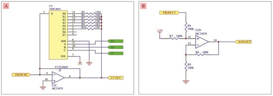
Figure 3.
(A) Current-to-voltage converter circuit, (B) Positive voltage summing amplifier circuit.
- D.
- Positive voltage summing amplifier circuit
The circuit in Figure 3B was built from an op-amp MC33079, which functions to add up the negative voltage from the current-to-voltage converter into a positive voltage in increments of 1.5 V. This circuit is also called a voltage level shifter. The purpose of using this circuit is so that there is no negative voltage at the output.
- E.
- ADC
ADC serves to convert analog signals or voltages into digital signals. The ADC used here was a module in which there is an ADS1118 IC which has a 16-bit resolution and four inputs, namely A0, A1, A2, and A3 [18]. Only one input was used in this circuit, namely input A0. The ADC circuit and ports for serial communication via SPI with a microcontroller can be seen in Figure 4A. The ADC output from this circuit can then be processed digitally by the microcontroller.
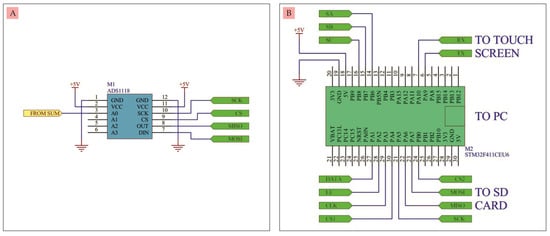
Figure 4.
(A) 16-bit ADC circuit, (B) Microcontroller.
- F.
- Microcontroller
The microcontroller functions to control the flow of data starting from adjusting the DAC output voltage, adjusting the speed of the voltage sweep, reading the voltage generated by the ADC which is a read current conversion, displaying all data in the form of graphs and numbers to the touch screen, storing data on the SD card, and/or transmitting data to the computer via the USB port. The microcontroller used was the STM32F411CEU6 module, which can process 32-bit data at a speed of 100 MHz [19], as can be seen in Figure 4B. This microcontroller is programmed in advance using STM32duino to run all stages of input and output settings, so that the potentiostat can work according toits function.
- G.
- Touch screen
The touch screen is used to display all input and output data in the form of graphs. In addition, potentiostat setting data and measurement steps can be displayed and can be adjusted using this touch screen. The touch screen used was Nextion 5 inch with type NX8048K050 [20]. Similar to the microcontroller, this touch screen must be programmed first using NextionEditor so that it can work as desired.
- H.
- SD card
The SD card functions to store all experimental data, starting from input data, output data, and setting data. The data is saved using the comma separated values (.CSV) format which is plain text that contains a list of data. For one experiment, a maximum storage capacity of 12 Kbyte is required, so if the SD card used is 8 Gigabyte, it can accommodate up to 600,000 experimental data.
- I.
- Battery
There are 3 lithium ion batteries used in this circuit with a voltage of 3.7 V and a capacity of 2500 mA which are installed in parallel. The circuit requires a symmetrical voltage of ±5 V so that a voltage conversion from a single voltage to a symmetrical voltage is required via the XL6007 DC to DV converter. The battery can supply the circuit for more than 14 h continuously.
3. Results and Discussion
- A.
- Casing design
The casing was designed using black acrylic to accommodate the circuit, battery and 5-inch touch screen, making it a compact and portable device. The casing design with dimensions of 150 × 95 × 45 mm can be seen in Figure 5.
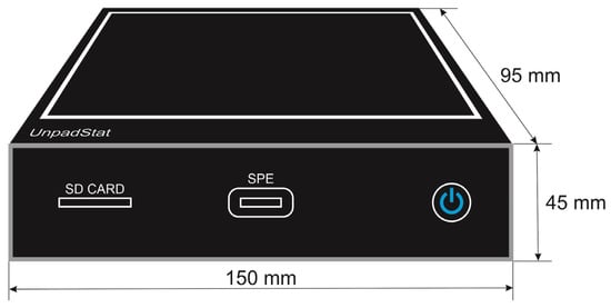
Figure 5.
Casing design.
- B.
- Specification
Specifications from UnpadStat and its comparison with the patent entitled Portable instrument for field ready electrochemical experimentation can be seen in Table 2.
Table 2.
Comparison of UnpadStat specifications with a patent entitled portable instrument for field ready electrochemical experimentation.
- C.
- Testing
The UnpadStat test was carried out using the cyclic voltammetry (CV) technique for two experiments. The first and second experiments were analyzed via a touch screen and connected to a computer using Microsoft Visual C# 2019 software. The measurement results displayed on the touch screen and on the computer were exactly the same, because the measurement data was sent simultaneously to both. The first experiment was a current measurement using a dummy circuit [3] consisting of one resistor (R) and one capacitor (C), as shown in Figure 6A. The second experiment was a current measurement using a commercial SPCE in Figure 6B.
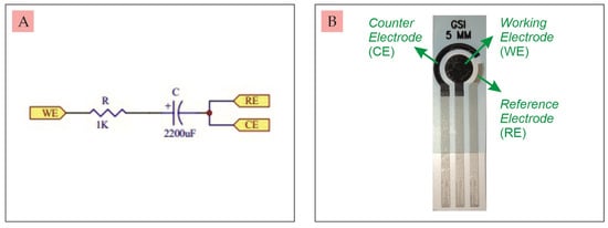
Figure 6.
(A) Dummy circuit, (B) Commercial SPCE.
The results of CV measurements on the dummy circuit can be seen in Figure 7A,B. Current graphs that are read tend to be stable. The voltage supplied by the potentiostat was from −1 V to +1 V at a speed of 80 mV/s with a resolution of 4 mV. The current generated after the process of charging and discharging the capacitor remained at a positive peak current of 176.64 µA and a negative peak current of −176.44 µA.
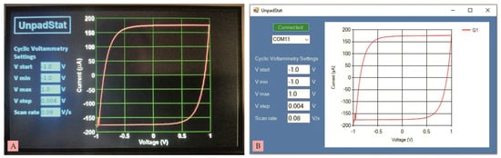
Figure 7.
(A) CV measurement on a dummy circuit using Nextion, (B) CV measurement on a dummy circuit using a computer.
The results of CV measurements on SPCE that had been dripped with 10 mM Ferricianide K3[FE(CN)6] solution can be seen in Figure 8A,B. The voltage given was the same as the previous test, namely from −1 V to +1 V at a speed of 80 mV/s with a resolution of 4 mV. The anodic peak is around 0.5 V and the cathodic peak is around −0.25 V. The resulting anodic peak current (Ipa) is 113.13 µA and the cathodic peak current (Ipc) is 156.72 µA.
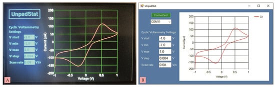
Figure 8.
(A) CV measurement on commercial SPCE using Nextion, (B) CV measurement on commercial SPCE using computer.
Furthermore, the results of CV measurements in the first and second experiments were compared with commercial potentiostats (Ana Pot X4—EIS—ZP). The results can be seen in Figure 9A,B, where the graphs in red are the results of UnpadStat measurements and the graphs in green are the results of the commercial potentiostat measurements. The accuracy of the CV measurement results on the dummy circuit and commercial SPCE can be seen in Table 3. The accuracy on the dummy circuit for Ipa is 95.88% and for Ipc is 96.12%, while the accuracy on the commercial SPCE for Ipa is 95.66% and for Ipc is 97.19%.
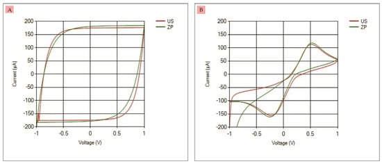
Figure 9.
(A) CV measurement on dummy circuit using UnpadStat and commercial potentiostat, (B) CV measurement on commercial SPCE using UnpadStat and commercial potentiostat.
Table 3.
Comparison of CV measurement results.
The last measurement was the CV measurement on SPCE which had been dripped with 15 mM, 10 mM, and 5 mM Ferricianide K3[FE(CN)6] solution. The voltage supplied was from −1 V to +1 V at a speed of 50 mV/s with a resolution of 4 mV. The measurement results can be seen in Figure 10. The higher the concentration of the solution, the higher the Ipa and Ipc.
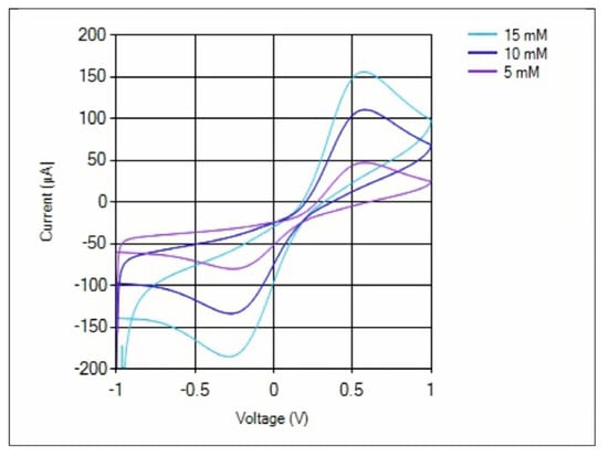
Figure 10.
CV measurement on SPCE which had been dripped with 15 mM, 10 mM, and 5 mM Ferricianide K3[FE(CN)6] solution.
4. Conclusions
In this study a potentiostat (UnpadStat) designed for three-electrode electrochemical sensing measurements worked well. The resulting graphics are clear without significant noise, both on the touch screen and on the computer. UnpadStat’s accuracy is quite high on the 4th measurement scale (15 KΩ multiplier resistor), with a voltage sweep from −1 V to +1 V at a speed of 80 mV/s with a resolution of 4 mV. The accuracy obtained when compared with a commercial potentiostat for measuring dummy circuit and commercial SPCE is more than 90%. Data can also be stored on an SD card in .CSV format of 12 kilobytes, so using an SD card with a capacity of 8 gigabytes can store up to 600,000 trial data.
Author Contributions
Conceptualization, R.S. and Y.W.H.; methodology, Y.W.H. and A.A.; software, R.S.; validation, R.S. and Y.W.H.; formal analysis, R.S. and T.F.H.L.; investigation, R.S. and T.F.H.L.; data curation, R.S.; Resources, Y.W.H. and H.H.B.; writing—original draft preparation, R.S.; writing—review and editing, Y.W.H. and H.H.B.; supervision, Y.W.H., A.A. and H.H.B.; funding acquisition, Y.W.H. and H.H.B. All authors have read and agreed to the published version of the manuscript.
Funding
This research was funded by PTUPT Scheme and PDD scheme No.2064/UN6.3.1/PT.00/2022, and ALG Scheme No. 2203/UN6.3.1/PT.00/2022 (Husein H. Bahti).
Data Availability Statement
Not applicable.
Acknowledgments
The authors express acknowledgment to the Indonesian Ministry of Higher Education and Culture and Padjadjaran University who have supported this research and funded the article publishing charge.
Conflicts of Interest
The authors declare no conflict of interest.
References
- Joshi, P.S.; Sutrave, D.S. Building an Arduino based potentiostat and Instrumentation for Cyclic Voltammetry. J. Appl. Sci. Comput. 2016, 5, 162–167. [Google Scholar]
- Glasscott, M.W.; Verber, M.D.; Hall, J.R.; Penergast, A.D.; McKinney, C.J.; Dick, J.E. SweepStat: A build-it-yourself, two-electrode potentiostat for macroelectrode and ultramicroelectrode studies. J. Chem. Educ. 2020, 97, 265–270. [Google Scholar] [CrossRef]
- Dobbelaere, T.; Vereecken, P.M.; Detavernier, C. A USB-controlled potentiostat/galvanostat for thin-film battery characterization. HardwareX 2017, 2, 34–49. [Google Scholar] [CrossRef]
- Meloni, G.N. Building a microcontroller based potentiostat: A inexpensive and versatile platform for teaching electrochemistry and instrumentation. J. Chem. Educ. 2016, 93, 1320–1322. [Google Scholar] [CrossRef]
- Rowe, A.A.; Bonham, A.J.; White, R.J.; Zimmer, M.P.; Yadgar, R.J.; Hobza, T.M.; Honea, J.W.; Ben-Yaacov, I.; Plaxco, K.W. CheapStat: An open-source, “Do-It-Yourself” potentiostat for analytical and educational applications. PLoS ONE 2011, 6, e23783. [Google Scholar] [CrossRef]
- Dryden, M.D.M.; Wheeler, A.R. DStat: A Versatile, Open-Source Potentiostat for Electroanalysis and Integration. PLoS ONE 2015, 10, e0140349. [Google Scholar] [CrossRef] [PubMed]
- Huang, C.Y. Design of a Portable Potentiostat with Dual-microprocessors for Electrochemical Biosensors. Univers. J. Electr. Electron. Eng. 2015, 3, 159–164. [Google Scholar] [CrossRef]
- Nordin, N.A.; Jamil, A.J.; Mat Som, A.S.C.; Abdullah, W.F.H.; Zain, Z.M.; Hamid, U.M.A.; Rani, S. Potentiostat Readout Circuit Design for a 3-Electrode Electrochemical Biosensing Measurement System. In Proceedings of the 2016 IEEE 7th Control and System Graduate Research Colloquium (ICSGRC 2016), UiTM Shah Alam, Malaysia, 8 August 2016. [Google Scholar]
- Ainla, A.; Mousavi, M.P.S.; Tsaloglou, M.; Redston, J.; Bell, J.G.; Fernandez-Abedul, M.T.; Whitesides, G.M. Open-source potentiostat for wireless electrochemical detection with smartphones. Anal. Chem. 2018, 90, 6240–6246. [Google Scholar] [CrossRef] [PubMed]
- Ahmad, R.; Surya, S.G.; Sales, J.B.; Mkaouar, H.; Catunda, S.Y.; Belfort, D.R.; Lei, Y.; Wang, Z.L.; Baeumner, A.; Wolfbeis, O.S.; et al. KAUSTat: A wireless, wearable, open-source potentiostat for electrochemical measurements. In Proceedings of the 2019 IEEE Sensors, Montreal, QC, Canada, 27–30 October 2019; pp. 1–4. [Google Scholar]
- Giordano, G.F.; Vicentini, M.B.; Murer, R.C.; Augusto, F.; Ferrão, M.F.; Helfer, G.A.; da Costa, A.B.; Gobbi, A.L.; Hantao, L.W.; Lima, R.S. Point-of-use electroanalytical platform based on homemade potentiostat and smartphone for multivariate data processing. Electrochim. Acta 2016, 219, 170–177. [Google Scholar] [CrossRef]
- Sun, A.; Wambach, T.; Venkatesh, A.G.; Hall, D.A. A low-cost smartphone-based electrochemical biosensor for point-of-care diagnostics. In Proceedings of the 2014 IEEE Biomedical Circuits and Systems Conference (BioCAS), Launsanne, Swizerland, 22–24 October 2014; pp. 312–315. [Google Scholar]
- Heien, M.L.; Farrell, D. Portable Instrument for Field Ready Electrochemical Experimentation. U.S. Patent 2019/0170687 A1, 6 June 2019. [Google Scholar]
- Hartati, Y.W.; Gaffar, S.; Alfiani, D.; Pratomo, U.; Sofiatin, Y.; Subroto, T. A voltammetric immunosensor based on gold nanoparticle-Anti-ENaC bioconjugate for the detection of epithelial sodium channel (ENaC) protein as a biomarker of hypertension. Sens. Bio-Sens. Res. 2020, 29, 100343. [Google Scholar] [CrossRef]
- PCM56P Datasheet, Texas Instruments. Available online: https://www.ti.com/lit/ds/symlink/pcm56.pdf (accessed on 14 May 2021).
- MC33079, Datasheet, STMicroelectronics. Available online: https://www.st.com/resource/en/datasheet/mc33079.pdf (accessed on 3 May 2021).
- 74HC4051 Datasheet, Texas Instruments. Available online: https://www.ti.com/lit/ds/symlink/cd74hc4051.pdf?ts=1663563794461&ref_url=https%253A%252F%252Fwww.ti.com%252Fproduct%252FCD74HC4051 (accessed on 21 July 2021).
- ADS1118 Datasheet, Texas Instruments. Available online: https://www.ti.com/lit/pdf/sbas457 (accessed on 30 June 2022).
- STM32F411CEU6, Datasheet, STMicroelectronics. Available online: https://www.st.com/resource/en/datasheet/stm32f411re.pdf (accessed on 2 July 2022).
- NX8048K050, Datasheet. Available online: https://nextion.tech/datasheets/nx8048k050/# (accessed on 25 July 2021).


Disclaimer/Publisher’s Note: The statements, opinions and data contained in all publications are solely those of the individual author(s) and contributor(s) and not of MDPI and/or the editor(s). MDPI and/or the editor(s) disclaim responsibility for any injury to people or property resulting from any ideas, methods, instructions or products referred to in the content. |
© 2023 by the authors. Licensee MDPI, Basel, Switzerland. This article is an open access article distributed under the terms and conditions of the Creative Commons Attribution (CC BY) license (https://creativecommons.org/licenses/by/4.0/).