
Origami Inspired Laser Scanner


Abstract
1. Introduction
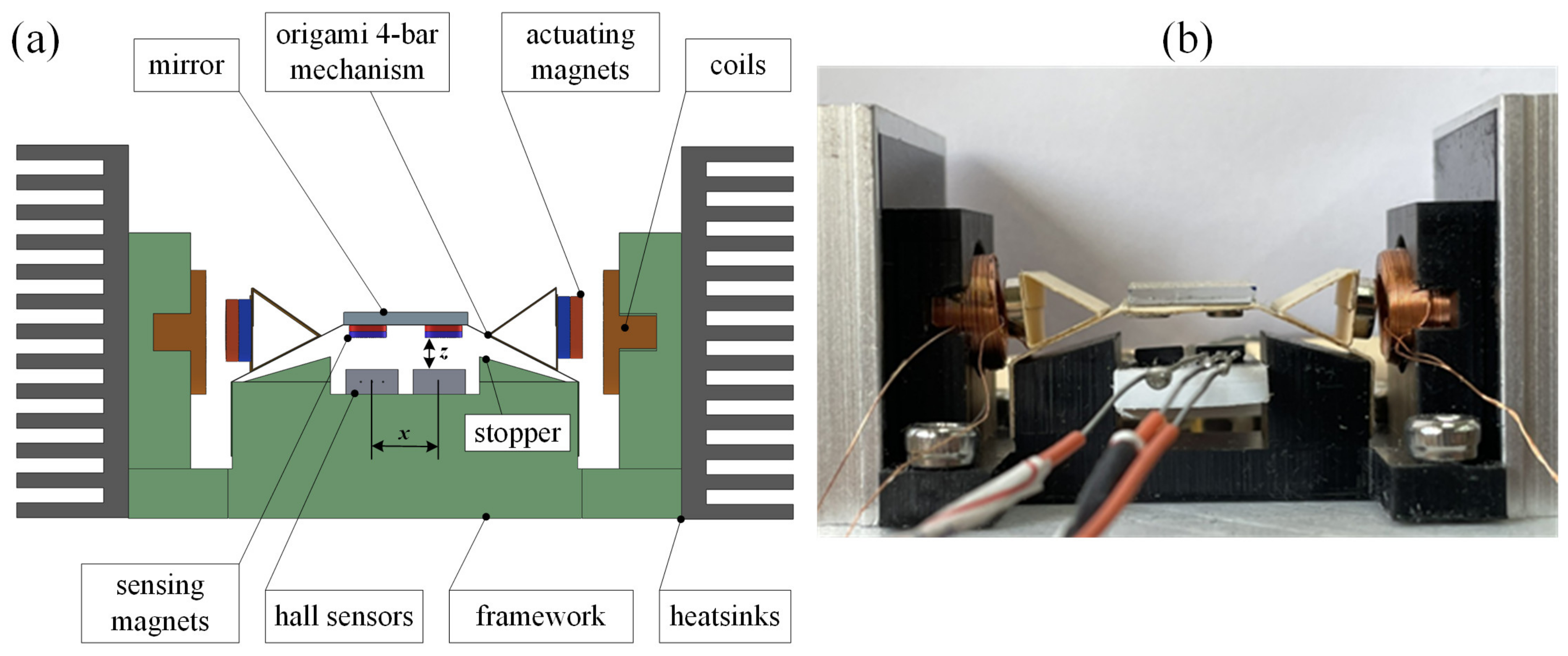
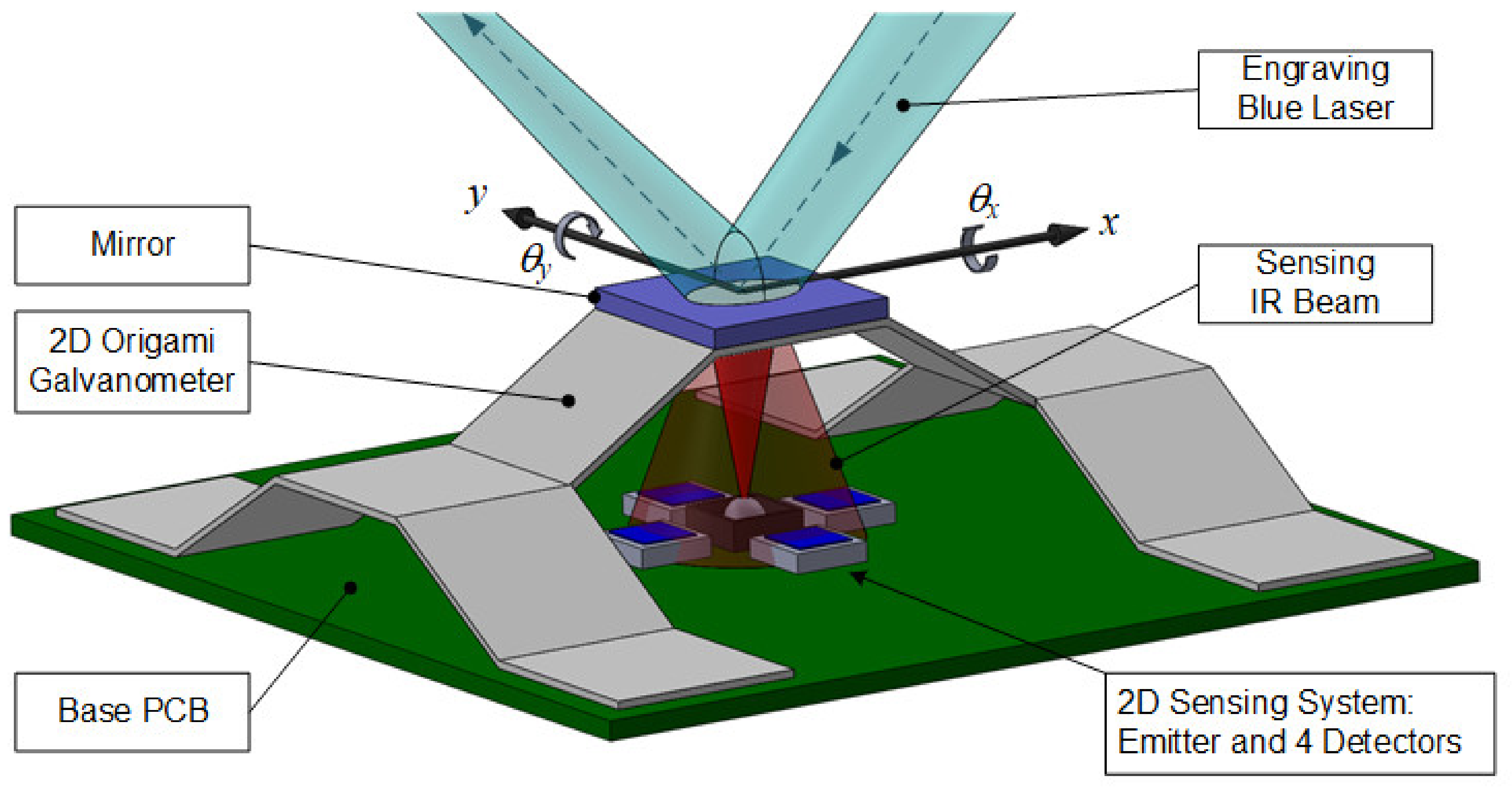
2. Design
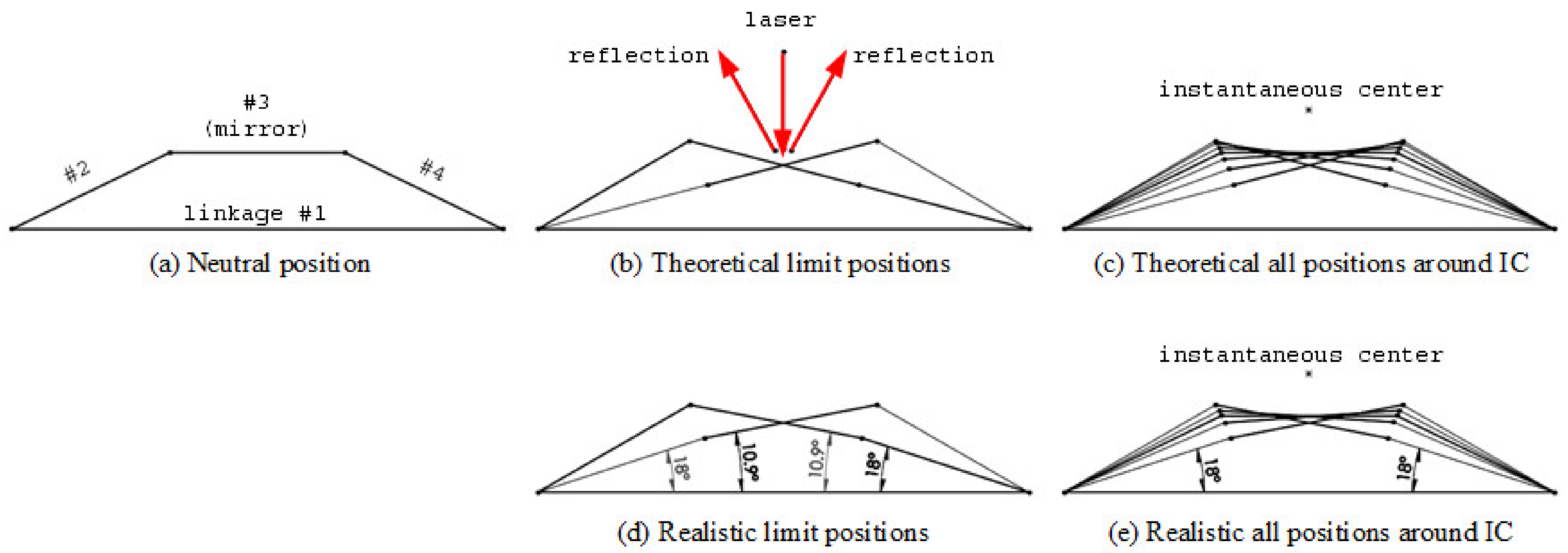
2.1. Paper Mechanism
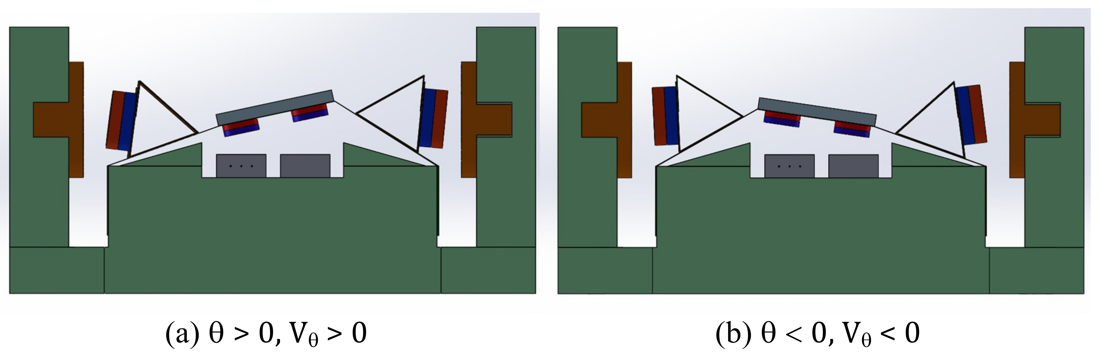
2.2. Actuators
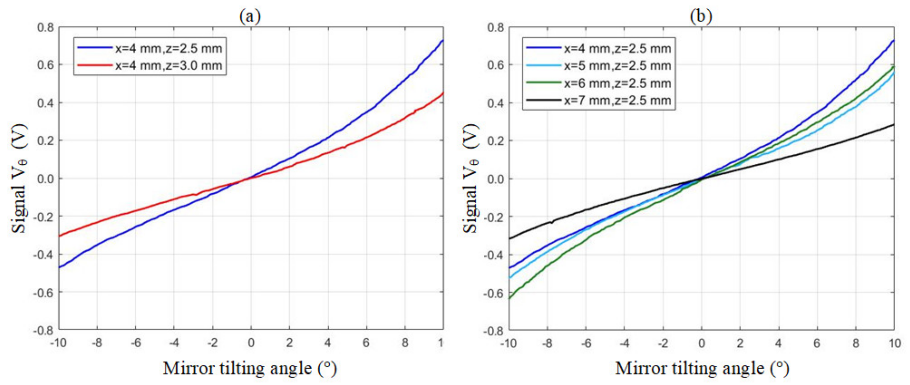
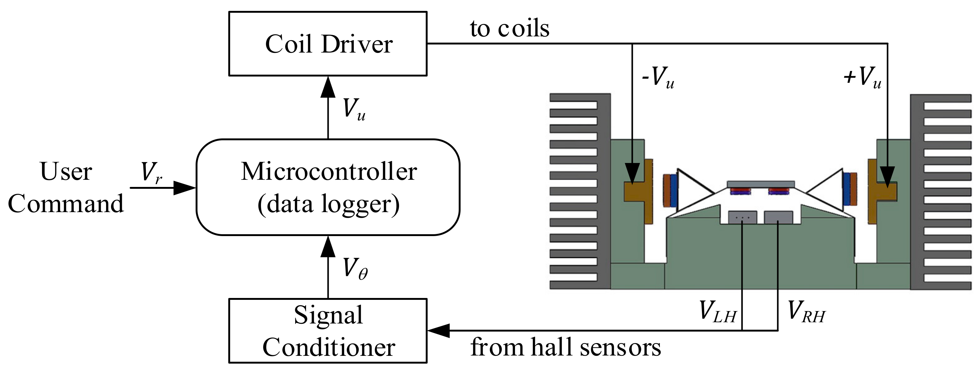
2.3. Sensors
3. Experiment
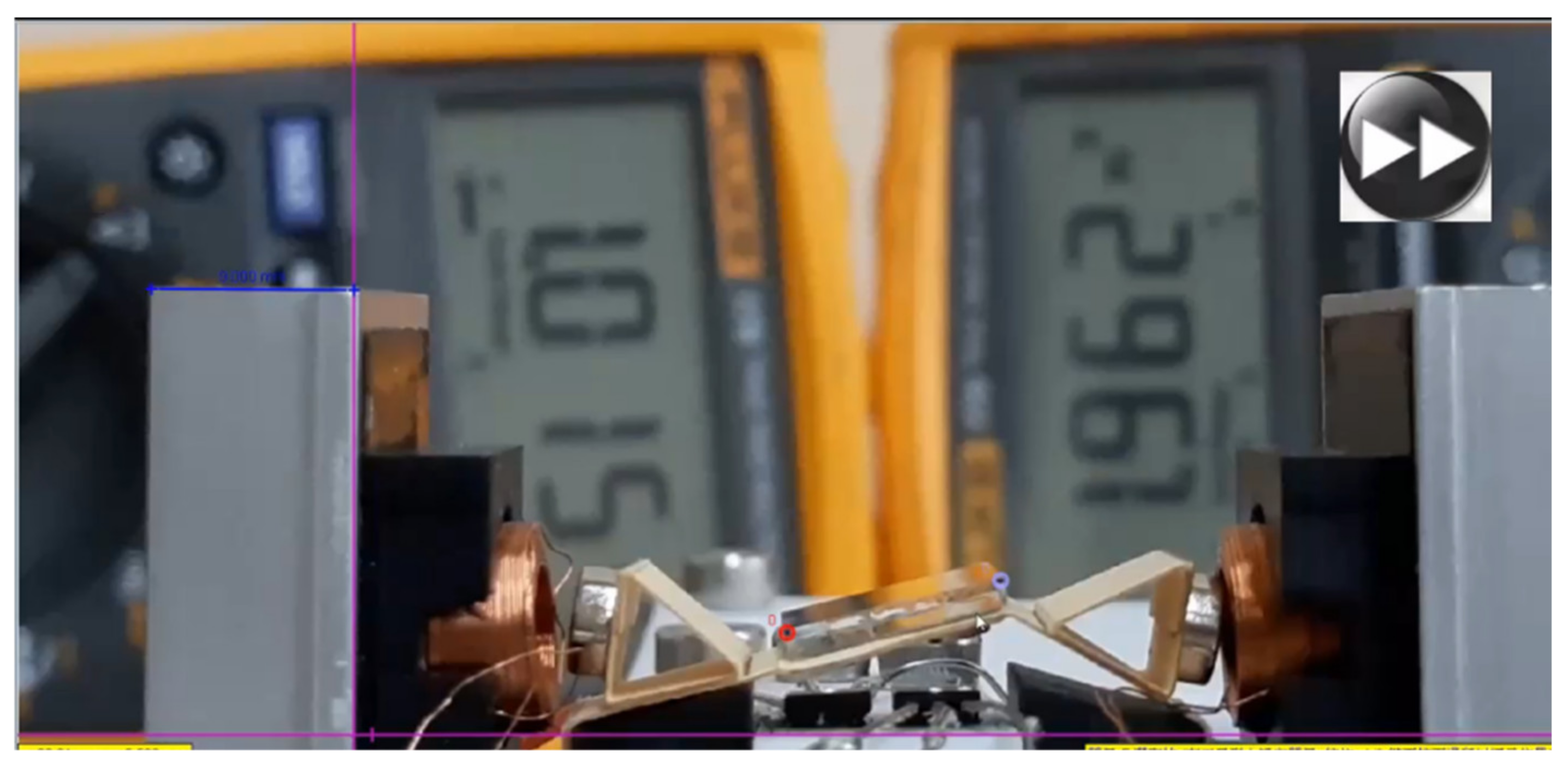
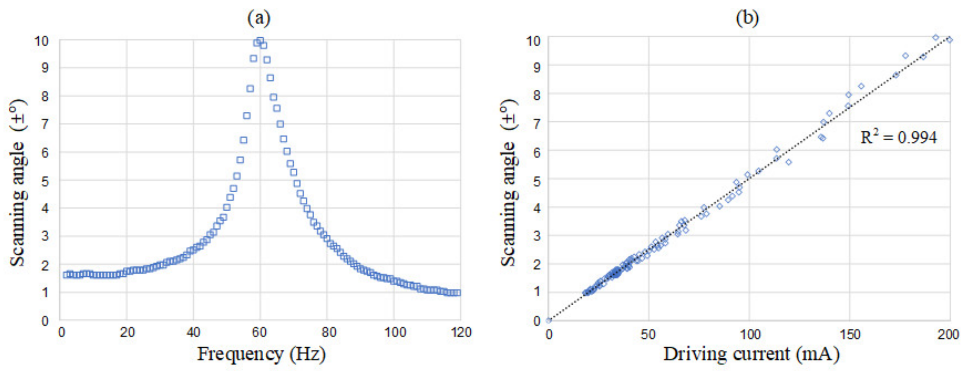
3.1. Instrument Setup
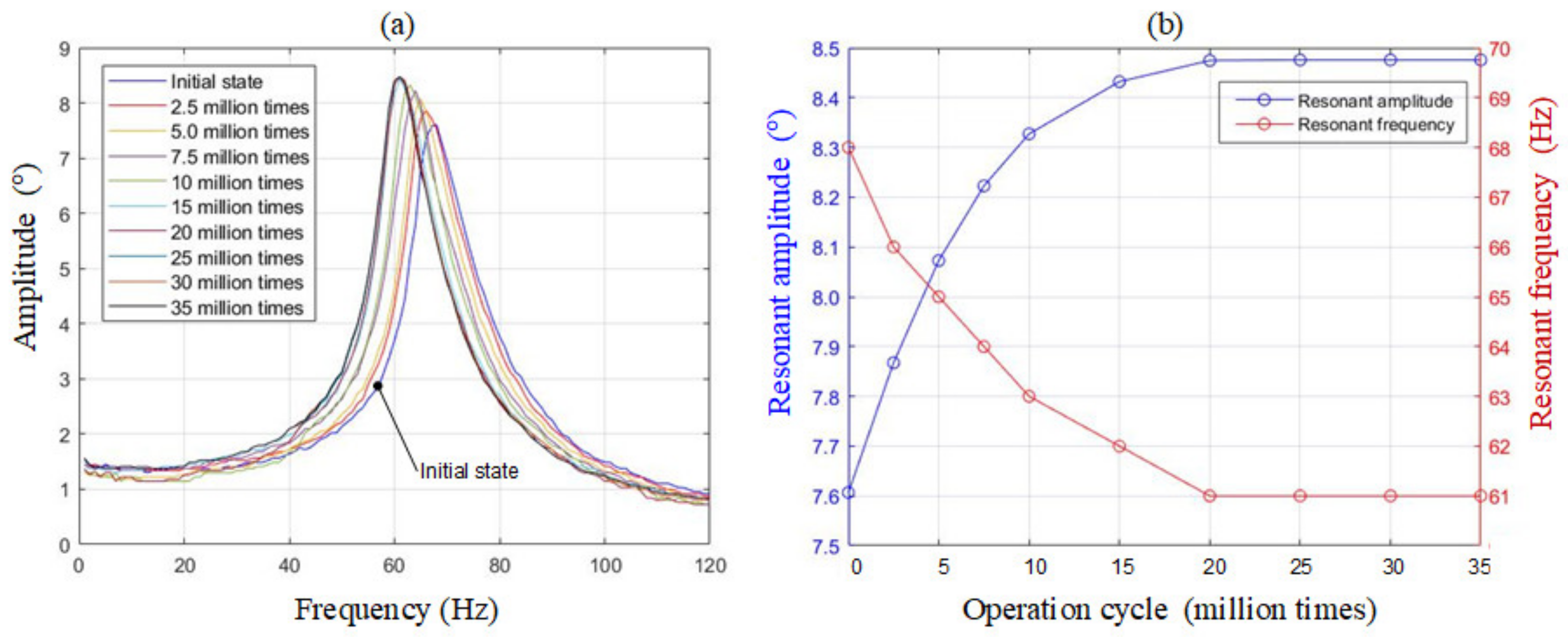
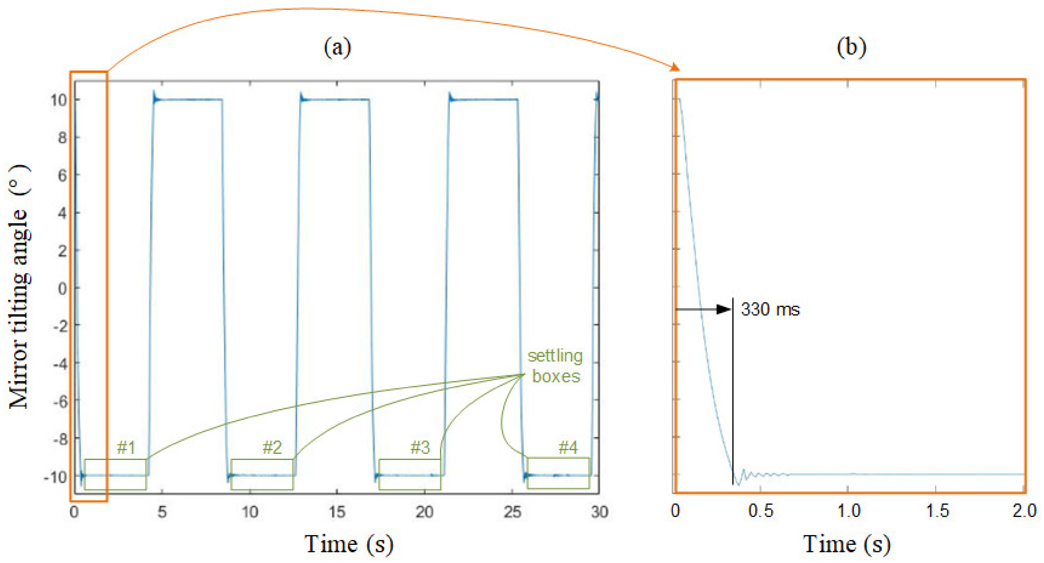
3.2. Durability Test
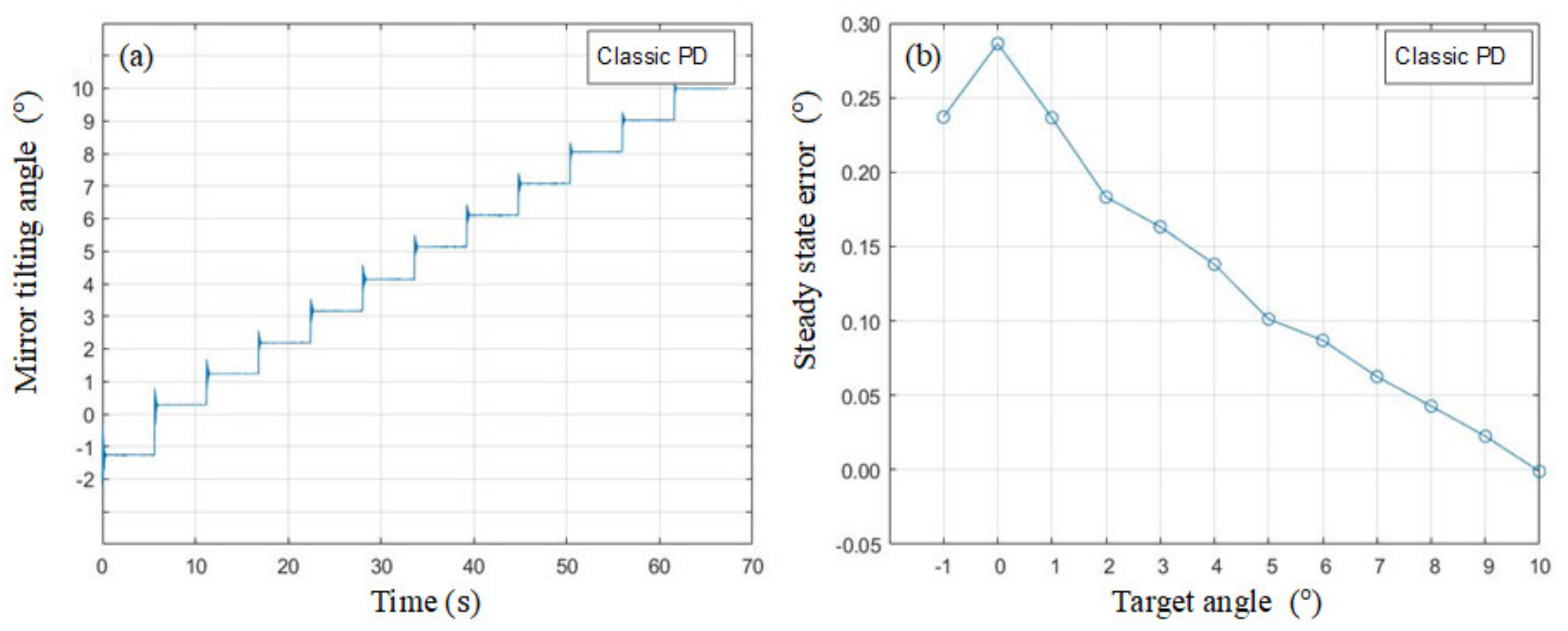
3.3. Classic PD Control
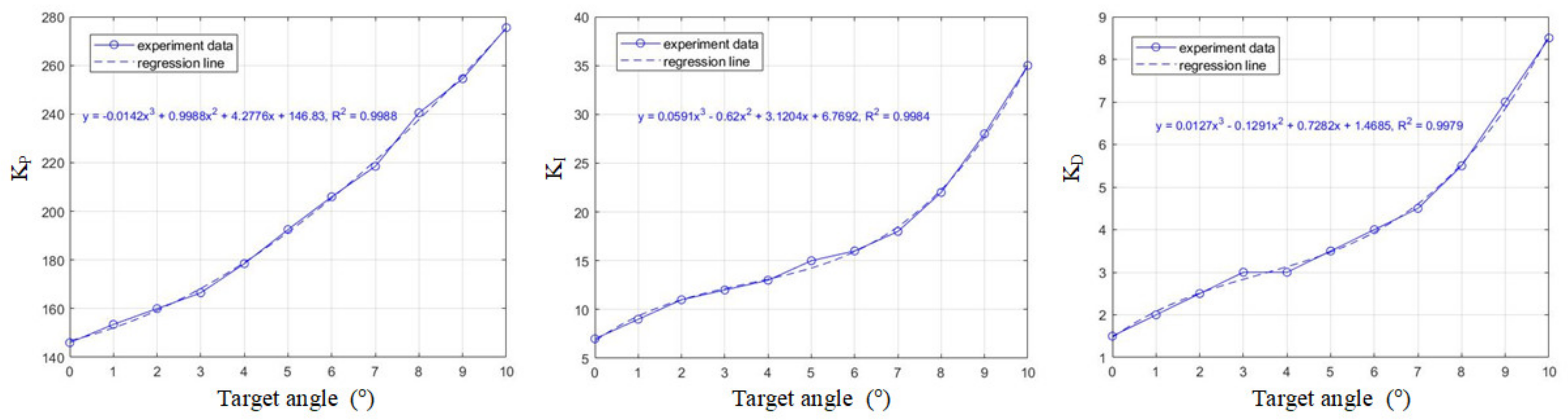
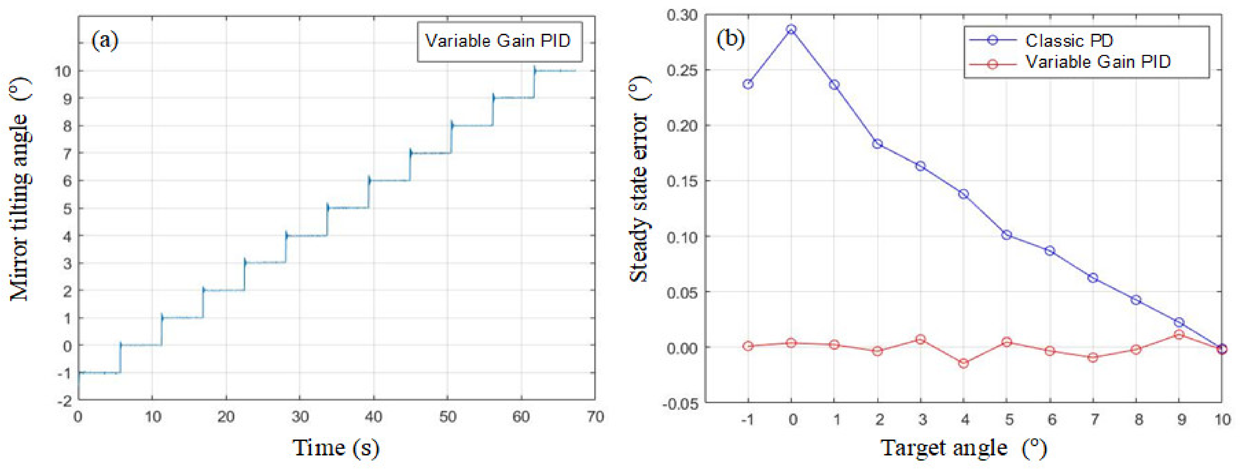
3.4. Variable Gain PID Control
4. Discussion
5. Conclusions and Outlook
Author Contributions
Funding
Institutional Review Board Statement
Informed Consent Statement
Data Availability Statement
Acknowledgments
Conflicts of Interest
References
- Cubiio: Laser Your Ideas Anytime Anywhere. Available online: https://www.kickstarter.com/projects/cubiio/cubiio-the-most-compact-laser-engraver (accessed on 7 September 2022).
- Zuo, H.; He, S. 1D LiDAR Based on Large Aperture FPCB Mirror. In Proceedings of the International Conference on Optical MEMS and Nanophotonics, KAIST, Daejeon, Korea, 28 July–1 August 2019. [Google Scholar]
- Tan, V.J.; He, S. Oscillation FPCB micromirror based triangulation laser rangefinder. J. Micromech. Microeng. 2020, 30, 95008. [Google Scholar] [CrossRef]
- Zuo, H.; He, S. Extra Large Aperture FPCB Mirror Based Scanning LiDAR. IEEE/ASME Trans. Mechatron. 2021; accepted. [Google Scholar] [CrossRef]
- Melchels, F.P.W.; Feijen, J.; Grijpma, D.W. A review on stereolithography and its applications in biomedical engineering. Biomaterials 2010, 31, 6121–6130. [Google Scholar] [CrossRef]
- Kruth, J.-P.; Mercelis, P.; Vaerenbergh, J.V. Binding mechanisms in selective laser sintering and selective laser melting. Rapid Prototyp. J. 2005, 11, 26–36. [Google Scholar] [CrossRef]
- Krant, J.; Deter, C.; Gessner, T.; Dotzel, W. Laser Display Technology. In Proceedings of the IEEE International Conference on Micro Electro Mechanical Systems, Heidelberg, Germany, 25–29 January 1998. [Google Scholar]
- Davis, W.O.; Sprague, R.; Miller, J. MEMS-Based Pico Projector Display. In Proceedings of the IEEE/LEOS International Conference on Optical MEMS, Freiburg, Germany, 11–14 August 2008. [Google Scholar]
- Perry, T.S. Tomorrow’s TV. IEEE Spectr. 2004, 41, 38–41. [Google Scholar] [CrossRef]
- Zuo, H.; He, S. FPCB Micromirror-Based Laser Projection Availability Indicator. IEEE Trans. Ind. Electron. 2016, 63, 3009–3018. [Google Scholar] [CrossRef]
- Zuo, H.; He, S. FPCB Ring-Square Electrode Sandwiched Micromirror-Based Laser Pattern Pointer. IEEE Trans. Ind. Electron. 2017, 64, 6319–6329. [Google Scholar] [CrossRef]
- Bizheva, K.; Tan, B.; Maclelan, B.; Kralj, O.; Hajialamdari, M.; Hileeto, D.; Sorbara, L. Sub-micrometer axial resolution OCT for invivo imaging of the cellular structure of healthy and keratoconic human corneas. Biomed. Opt. Express 2017, 8, 800–812. [Google Scholar] [CrossRef]
- Pellegrini, E.; Robertson, G.; MacGillivray, T.; Hemert, J.V.; Houston, G.; Trucco, E. A Graph Cut Approach to Artery/Vein Classification in Ultra-Widefield Scanning Laser Ophthalmoscopy. IEEE Trans. Med. Imaging 2018, 37, 516–526. [Google Scholar] [CrossRef]
- Webb, R.H.; Hughes, G.W. Scanning Laser Ophthalmoscope. IEEE Trans. Biomed. Eng. 1981, 28, 488–492. [Google Scholar] [CrossRef]
- Lei, H.; Wen, Q.; Yu, F.; Zhou, Y.; Wen, Z. FR4-Based Electromagnetic Scanning Micromirror Integrated with Angle Sensor. Micromachines 2018, 9, 214. [Google Scholar] [CrossRef] [PubMed]
- Periyasammy, K.G.K.; Tan, V.J.; He, S.; Kourtzanidis, N. External Electromagnet FPCB Micromirror for Large Angle Laser Scanning. Micromachines 2019, 10, 667. [Google Scholar] [CrossRef] [PubMed]
- Urey, H.; Holmstrom, S.; Yalcinkaya, A.D. Electromagnetically Actuated FR4 Scanners. IEEE Photonics Technol. Lett. 2020, 20, 30–32. [Google Scholar] [CrossRef]
- Wen, Q.; Lei, H.; Yu, F.; Li, D.; She, Y.; Huang, J.; Huang, L.; Wen, Z. Investigation of Electromagnetic Angle Sensor Integrated in FR4-Based Scanning Micromirror. Appl. Sci. 2018, 8, 2412. [Google Scholar] [CrossRef]
- Scanlab Innovators for Industry. Available online: https://www.scanlab.de/en/products/galvanometer-scanners (accessed on 7 September 2022).
- Morgan, J.; Magleby, S.P.; Howell, L.L. An Approach to Designing Origami-Adapted Aerospace Mechanisms. J. Mech. Des. 2016, 138, 52301. [Google Scholar] [CrossRef]
- Kuribayashi, K.; Tsuchiya, K.; You, Z.; Tomus, D.; Umemoto, M.; Ito, T.; Sasaki, M. Self-deployable origami stent grafts as a biomedical application of Ni-rich TiNi shape memory alloy foil. Mater. Sci. Eng. A 2006, 419, 131–137. [Google Scholar] [CrossRef]
- You, Z.; Kuribayashi, K. A Novel Origami Stent. In Proceedings of the Summer Bioengineering Conference, Key Biscayne, FL, USA, 25–29 June 2003. [Google Scholar]
- Jasim, B.; Taheri, P. An Origami-Based Portable Solar Panel System. In Proceedings of the 2018 IEEE 9th Annual Information Technology, Electronics and Mobile Communication Conference (IEMCON), Vancouver, BC, Canada, 1–3 November 2018. [Google Scholar]
- Giraud, F.H.; Joshi, S.; Paik, J. Haptigami: A Fingertip Haptic Interface with Vibrotactile and 3-DoF Cutaneous Force Feedback. IEEE Trans. Haptics 2022, 15, 131–141. [Google Scholar] [CrossRef]
- Miyashita, S.; Guitron, S.; Ludersdorfer, M.; Sung, C.R.; Rus, D. An Untethered Miniature Origami Robot that Self-folds, Walks, Swims, and Degrades. In Proceedings of the 2015 International Conference on Robotics and Automation, Seattle, WA, USA, 25 May 2015. [Google Scholar]
- Firouzeh, A.; Paik, J. Robogami: A Fully Integrated Low-Profile Robotic Origami. J. Mech. Robot. 2015, 7, 21009. [Google Scholar] [CrossRef]
- Belke, C.H.; Paik, J. Mori: A Modular Origami Robot. IEEE/Asme Trans. Mechatron. 2017, 22, 2153–2164. [Google Scholar] [CrossRef]
- Paez, L.; Agarwal, G.; Paik, J. Design and Analysis of a Soft Pneumatic Actuator with Origami Shell Reinforcement. Soft Robot. 2016, 3, 3. [Google Scholar] [CrossRef]
- Zhang, H.; Feng, H.; Huang, J.-L.; Paik, J. Generalized modeling of origami folding joints. Extrem. Mech. Lett. 2021, 45, 101213. [Google Scholar] [CrossRef]
- Nelson, T.G.; Avila, A.; Howell, L.L.; Herder, L.L.; Machekposhti, D.F. Origami-inspired sacrificial joints for folding compliant mechanisms. Mech. Mach. Theory 2019, 140, 194–210. [Google Scholar] [CrossRef]
- Demaine, E.D.; Tachi, T. Origamizer: A Practical Algorithm for Folding Any Polyhedron. In Proceedings of the 33rd International Symposium on Computational Geometry, Brisbane, Australia, 4–7 July 2017. [Google Scholar]
- Chen, M.; Duan, X.; Lan, B.; Vu, T.; Zhu, X.; Rong, Q.; Yang, W.; Hoffmann, U.; Zou, J.; Yao, J. High-speed functional photoacoustic microscopy using a water-immersible two-axis torsion-bending scanner. Photoacoustics 2021, 24, 100309. [Google Scholar] [CrossRef]
- Cleghorn, W.L. Limit Positions and Time Ratio of Mechanisms. In Mechanics of Machines; Oxford University Press: Oxford, UK, 2010; pp. 57–61. [Google Scholar]
- Hung, S.-K.; Chung, Y.-S.; Chen, C.-L.; Chang, K.-H. Optoelectronic Angular Displacement Measurement Technology for 2-Dimensional Mirror Galvanometer. Sensors 2022, 22, 872. [Google Scholar] [CrossRef] [PubMed]
- Cleghorn, W.L. Special Cases of the Relative Acceleration Equation. In Mechanics of Machines; Oxford University Press: Oxford, UK, 2010; pp. 48–53. [Google Scholar]
- Arjowiggins Creative Papers. Available online: https://arjowigginscreativepapers.com/media/filer_public/6b/56/6b56dcef-e563-4ac5-ac72-e7bd7d526703/popset_technical_data_sheet_2019.pdf (accessed on 13 October 2022).
- Tracker Video Analysis and Modeling Tool. Available online: https://physlets.org/tracker/ (accessed on 7 September 2022).
- [PMEL] Origami Inspired Laser Galvanometer. Available online: https://youtu.be/y-gcLzzS5sc/ (accessed on 7 September 2022).
- Holmström, S.T.S.; Baran, U.; Urey, H. MEMS Laser Scanners: A Review. J. Microelectromech. Syst. 2014, 23, 259–275. [Google Scholar] [CrossRef]
- Yeh, R.-Y.; Chen, C.-L.; Lin, C.-T. Portable Laser Engraving/Cutting Apparatus. U.S. Patent 10,688,598 B2, 23 June 2020. [Google Scholar]


| [19] | [1] | Goals of This Work | |
|---|---|---|---|
| Recommended aperture | 10 mm | 10 mm | 10 mm |
| Actuator type | DC motor | Stepping motor | Voice coil motor |
| Bearing type | Ball bearing | Ball bearing | Origami hinges |
| Controller type | Closed-loop | Open-loop | Closed-loop |
| Scan range | ±12° | ±10° | ±10° |
| Repeatability (rms) | 5.73 × 10⁻⁵ degree | 0.04 degree | ≤0.004 degree |
| Settling time | 0.25 ms (for 1% of full scale) | 10 s (for full scale) | ≤1 s (for full scale) |
| Durability | Not available | 1.577 million cycles * | ≥15.77 million cycles |
| Cost | Very high | Medium | Low |
| Recommended aperture | 10 mm | 10 mm | 10 mm |
| Actuator type | DC motor | Stepping motor | Voice coil motor |
| Design Parameters | Values |
|---|---|
| Paper: thickness and areal density | 0.21 mm, 170 g/m2 |
| Mirror: weight and size | 0.7 g, 10 × 10 × 1.2 mm3 |
| 4-bar mechanism: length values | 28 mm, 10 mm, 10 mm, 10 mm |
| Driving magnets: size and surface flux density | φ 5 mm × 2 mm, 300 mT |
| Sensing magnets: size and surface flux density | φ 3 mm × 1 mm, 220 mT |
| Magnet-sensor gap | 2.5 mm |
| Sensor-sensor distance | 5 mm |
Publisher’s Note: MDPI stays neutral with regard to jurisdictional claims in published maps and institutional affiliations. |
© 2022 by the authors. Licensee MDPI, Basel, Switzerland. This article is an open access article distributed under the terms and conditions of the Creative Commons Attribution (CC BY) license (https://creativecommons.org/licenses/by/4.0/).
Share and Cite
Wu, Y.-S.; Hung, S.-K. Origami Inspired Laser Scanner. Micromachines 2022, 13, 1796. https://doi.org/10.3390/mi13101796
Wu Y-S, Hung S-K. Origami Inspired Laser Scanner. Micromachines. 2022; 13(10):1796. https://doi.org/10.3390/mi13101796
Chicago/Turabian StyleWu, Yu-Shin, and Shao-Kang Hung. 2022. "Origami Inspired Laser Scanner" Micromachines 13, no. 10: 1796. https://doi.org/10.3390/mi13101796
APA StyleWu, Y.-S., & Hung, S.-K. (2022). Origami Inspired Laser Scanner. Micromachines, 13(10), 1796. https://doi.org/10.3390/mi13101796