
Bionic Organs: Shear Forces Reduce Pancreatic Islet and Mammalian Cell Viability during the Process of 3D Bioprinting

 ,
,  , ,
, , 
Abstract
1. Introduction
2. Materials and Methods
2.1. Biological Material
- Pancreatic islets
- 3T3-L1 (Mus musculus fibroblasts)
- HFF-1 (human foreskin fibroblasts, ATCC SCRC-1041)
- INS-1E cells (β-cells from rat pancreas, insulinoma)
- αTC1.6 (αTC1 clone 6 α-cell from Mus musculus pancreas, adenoma)
- BALB-5206 (BALB/c Mouse Primary Pancreatic Microvascular Endothelial Cells, CellBiologist BALB-5206)
- HUVEC (Human Primary Umbilical Vein Endothelial Cells; ATCC PCS-100-010)
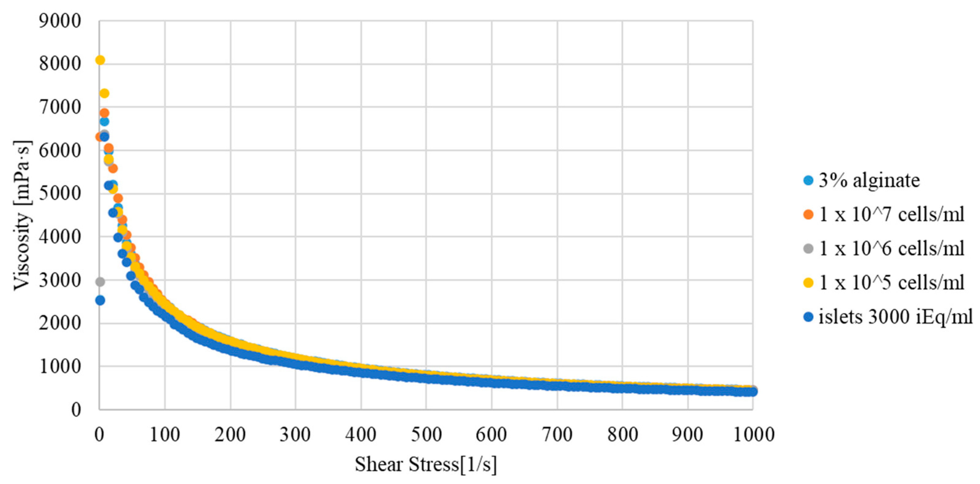
2.2. Hydrogel
- Bioink preparation and shear stress induction
- Preparation of material for research (bioink + biological material)
- (a)
- for pancreatic islets—3000 iEq/mL (viability around 90%)
- (b)
- for individual cell lines—5 × 10⁵ cells/mL (viability around 98%)
- 3D bioprinting parameters
2.3. Maximum Shear Stress Calculation
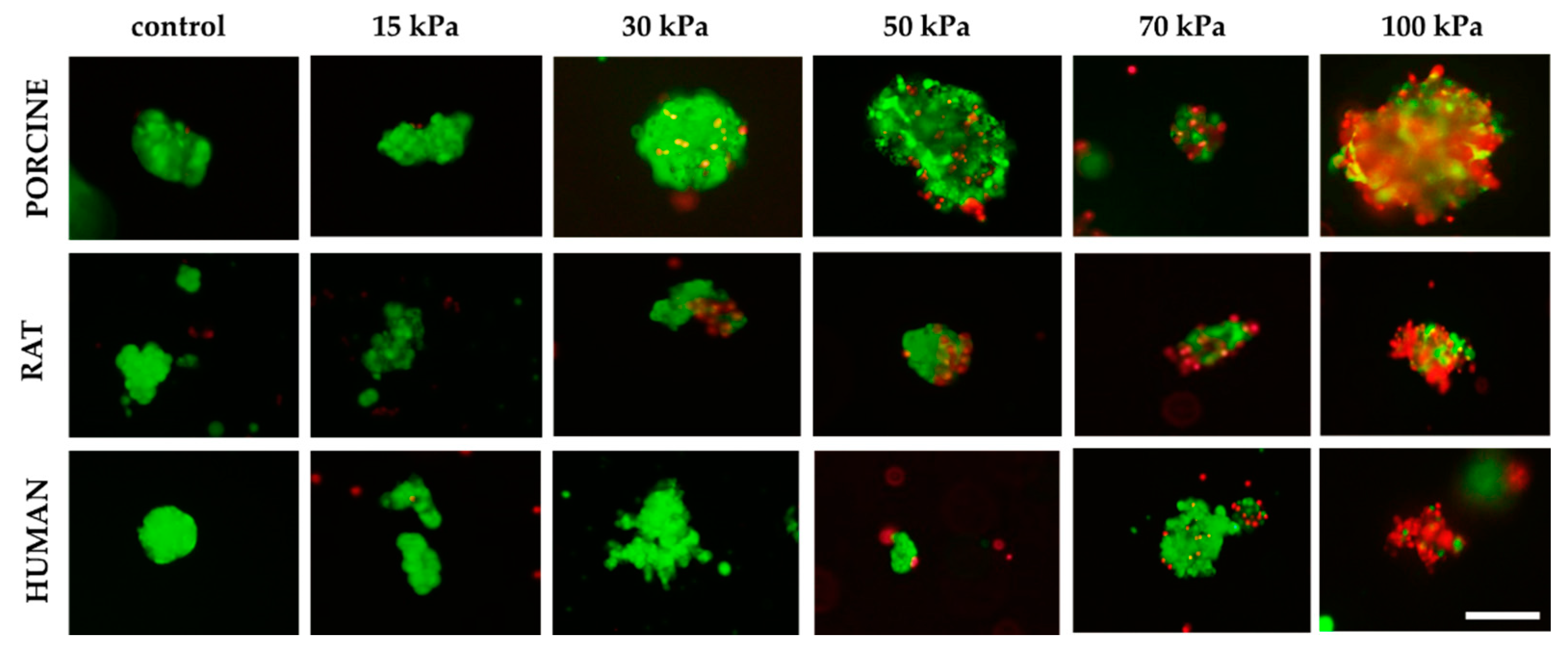
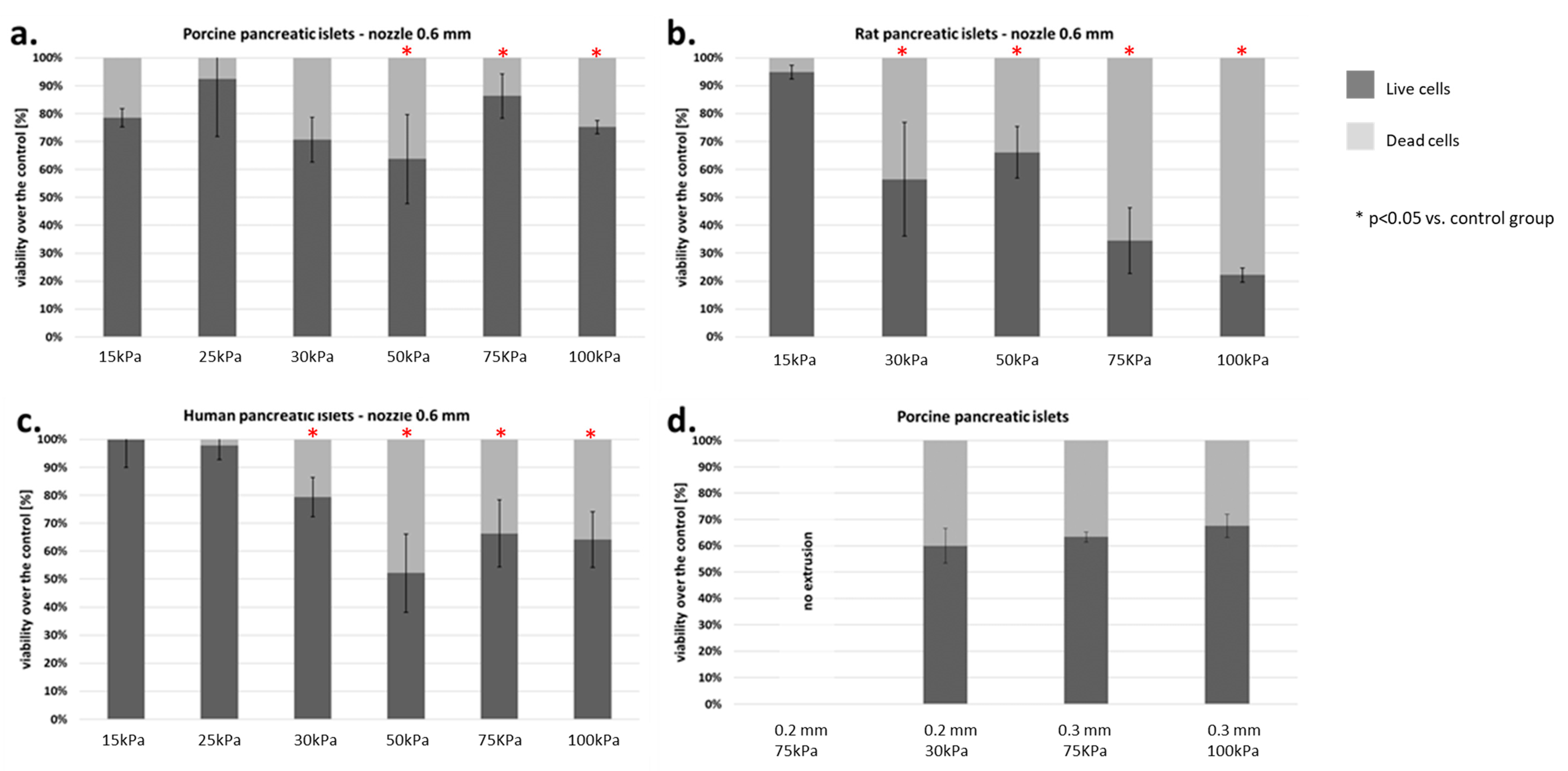
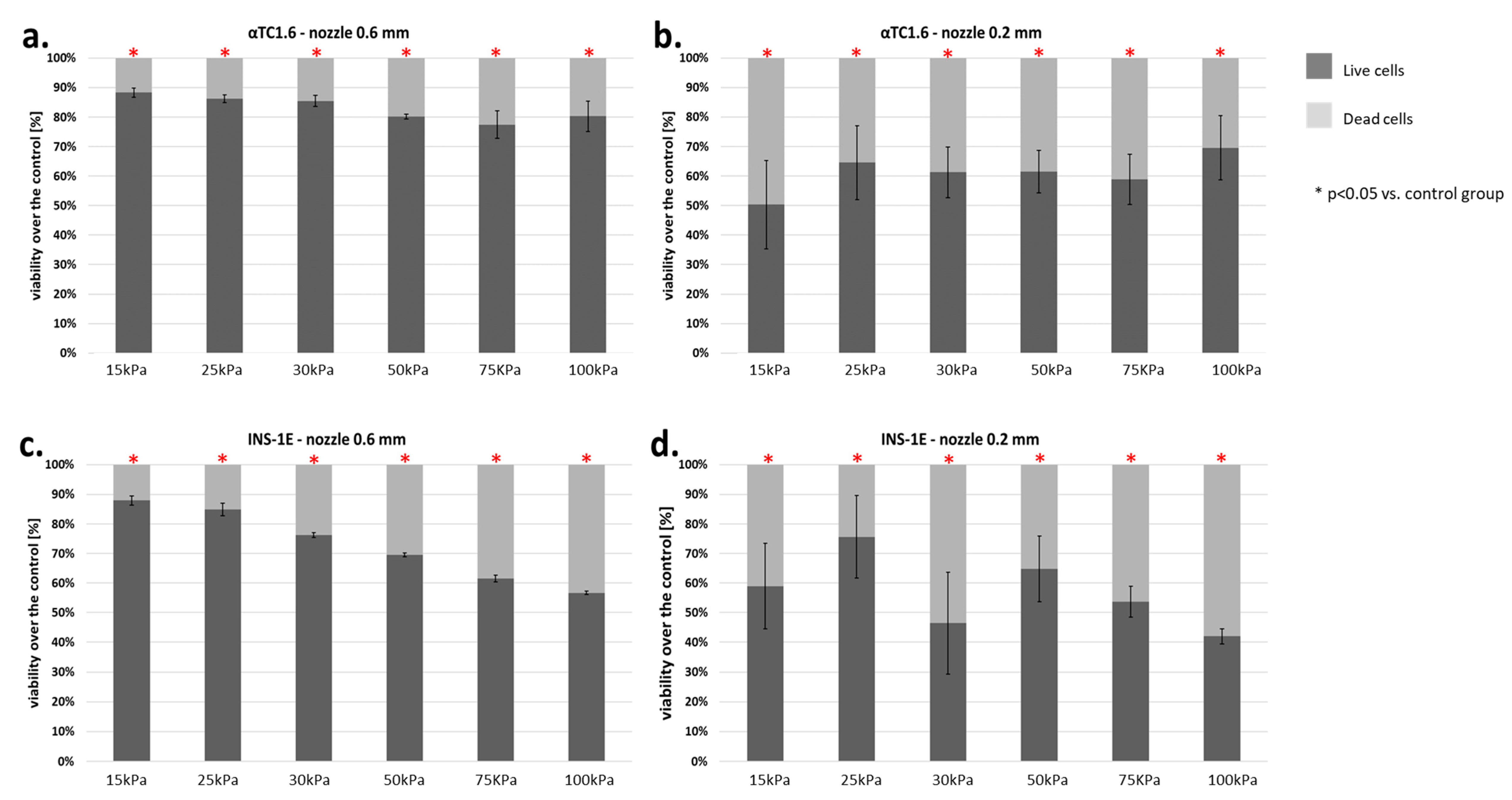
2.4. Assessment of Islet and Cell Viability
- Pancreatic islets:
- Cells:
2.5. Statistical Analysis
3. Results
3.1. Pancreatic Islets
3.2. Pancreatic Islet Cells
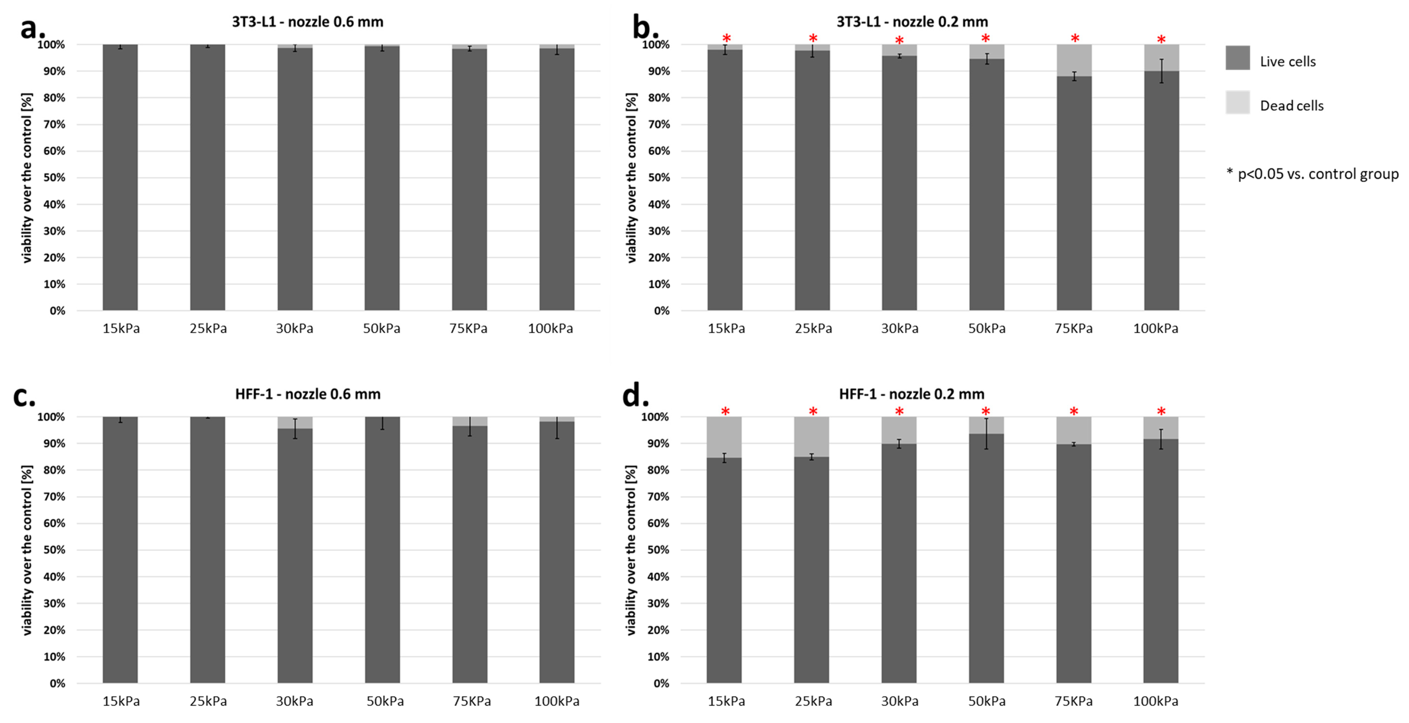
3.3. Fibroblasts Cells
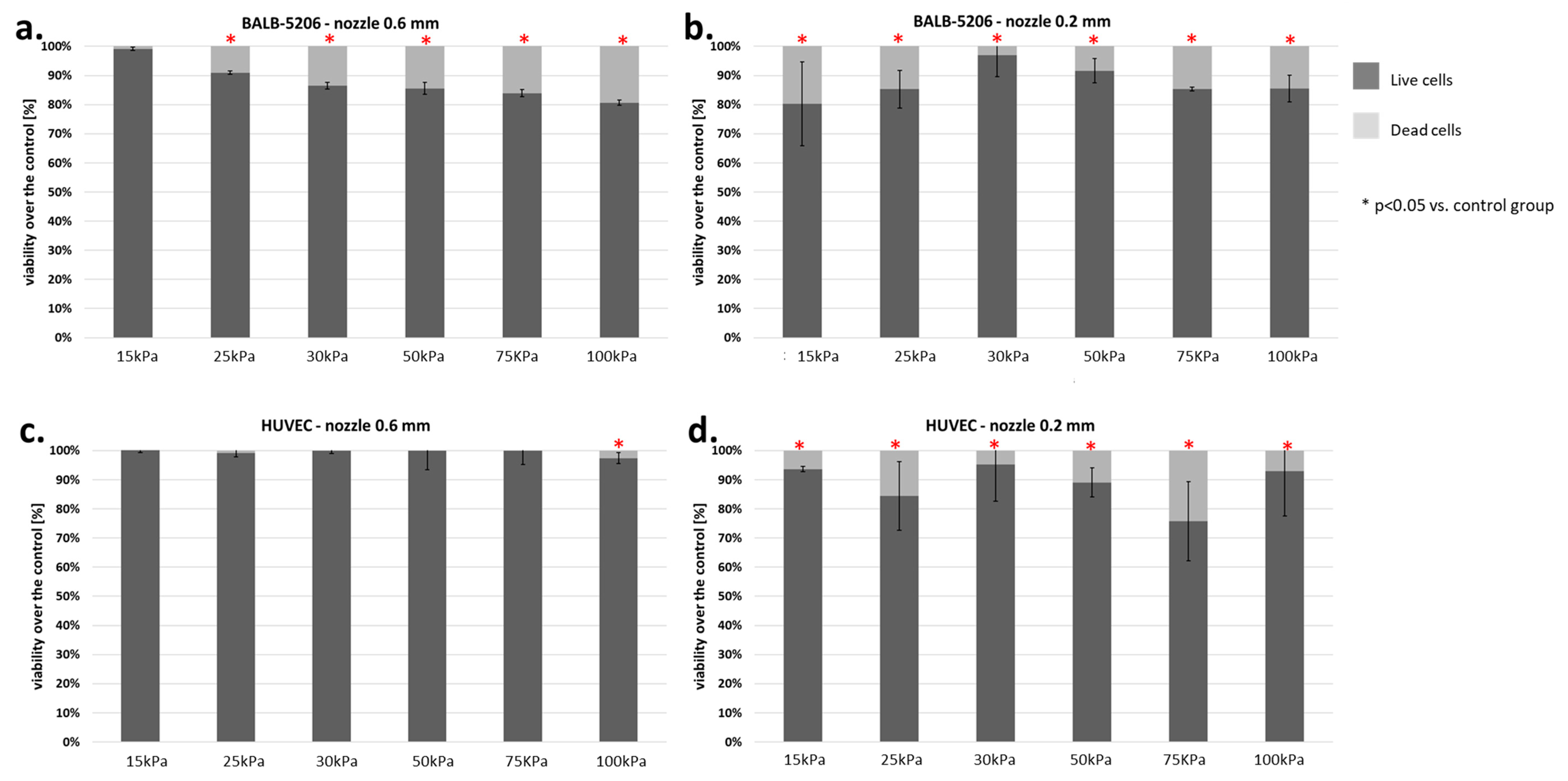
3.4. Endothelial Cells
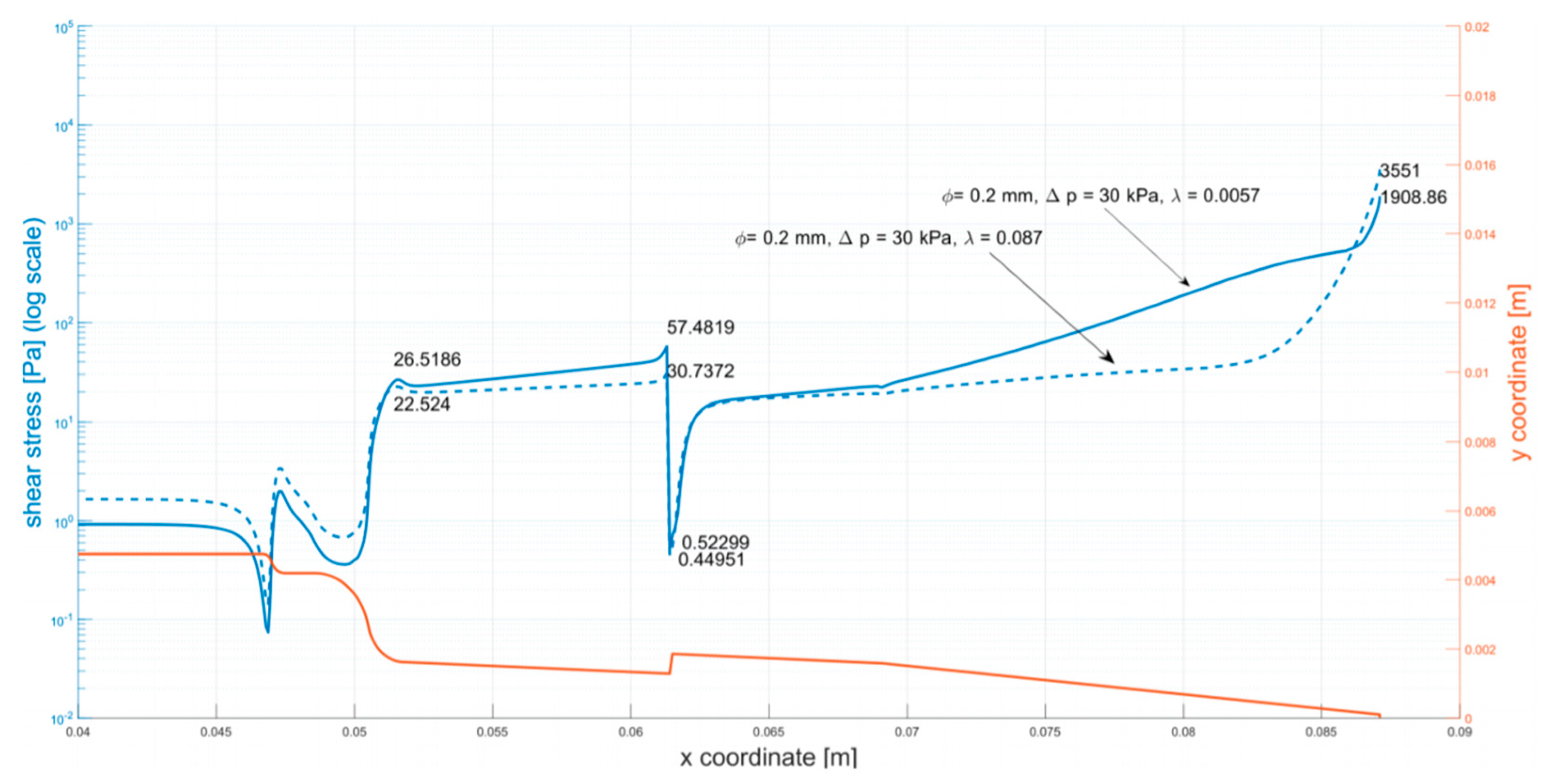
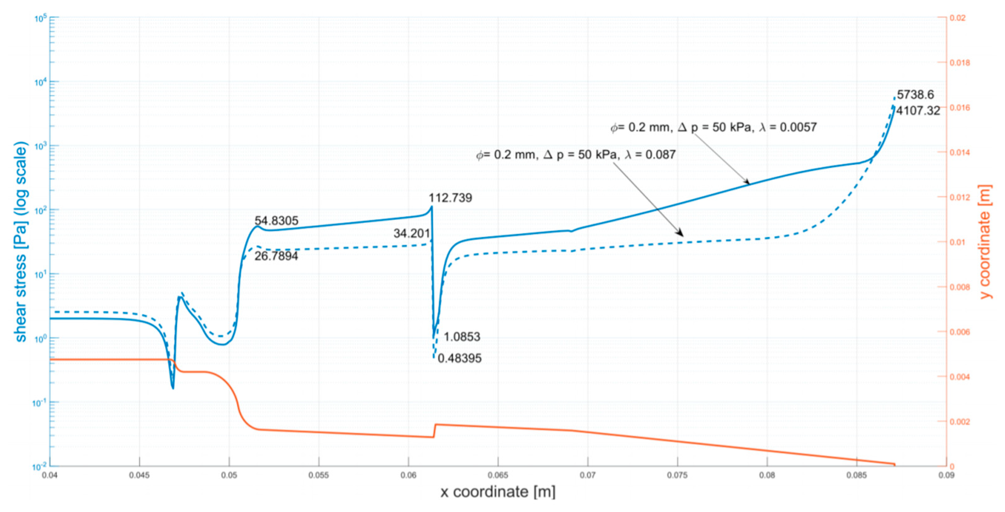
3.5. Cell Viability Analysis in Relation to Shear Stress Determined in Mathematical Models
4. Discussion
5. Conclusions
Author Contributions
Funding
Institutional Review Board Statement
Informed Consent Statement
Data Availability Statement
Conflicts of Interest
Appendix A


References
- Rosser, J.M.; Olmos-Calvo, I.; Schlager, M.; Purtscher, M.; Jenner, F. Recent Advances of Biologically Inspired 3D Microfluidic Hydrogel Cell Culture Systems. J. Cell Biol. Cell Metab. 2015, 2, 5. [Google Scholar]
- Nair, K.; Gandhi, M.; Khalil, S.; Yan, K.C.; Marcolongo, M.; Barbee, K.; Sun, W. Characterization of cell viability during bioprinting processes. Biotechnol. J. 2009, 4, 1168–1177. [Google Scholar] [CrossRef] [PubMed]
- Yu, Y.; Moncal, K.K.; Li, J.; Peng, W.; Rivero, I.; Martin, J.A.; Ozbolat, I.T. Three-dimensional bioprinting using self-Assembling scalable scaffold-free ‘tissue strands’ as a new bioink. Sci. Rep. 2016, 6, 1–11. [Google Scholar] [CrossRef] [PubMed]
- Klak, M.; Bryniarski, T.; Kowalska, P.; Gomolka, M.; Tymicki, G.; Kosowska, K.; Cywoniuk, P.; Dobrzanski, T.; Turowski, P.; Wszola, M. Novel Strategies in Artificial Organ Development: What Is the Future of Medicine? Micromachines 2020, 11, 646. [Google Scholar] [CrossRef] [PubMed]
- Dai, G.; Lee, V. Three-dimensional bioprinting and tissue fabrication: Prospects for drug discovery and regenerative medicine. Adv. Health Care Technol. 2015, 1, 23–35. [Google Scholar] [CrossRef]
- Leberfinger, A.N.; Dinda, S.; Wu, Y.; Koduru, S.V.; Ozbolat, V.; Ravnic, D.J.; Ozbolat, I.T. Bioprinting functional tissues. Acta Biomaterialia 2019, 1–71. [Google Scholar] [CrossRef] [PubMed]
- Blaeser, A.; Duarte Campos, D.F.; Puster, U.; Richtering, W.; Stevens, M.M.; Fischer, H. Controlling Shear Stress in 3D Bioprinting is a Key Factor to Balance Printing Resolution and Stem Cell Integrity. Adv. Healthcare Mater. 2016, 5, 326–333. [Google Scholar] [CrossRef] [PubMed]
- Hoang, D.T.; Matsunari, H.; Nagaya, M.; Nagashima, H.; Millis, J.M.; Witkowski, P.; Periwal, V.; Hara, M.; Jo, J. A conserved rule for pancreatic islet organization. PLoS ONE 2014, 9, 1–9. [Google Scholar] [CrossRef]
- Cabrera, O.; Berman, D.M.; Kenyon, N.S.; Ricordi, C.; Berggren, P.; Caicedo, A. The unique cytoarchitecture of human pancreatic islets has implications for islet cell function Over. PNAS 2006, 103, 1334–2339. [Google Scholar] [CrossRef] [PubMed]
- Ravnic, D.J.; Leberfinger, A.N.; Ozbolat, I.T. Bioprinting and Cellular Therapies for Type 1 Diabetes. Trends Biotechnol. 2017, 35, 1025–1034. [Google Scholar] [CrossRef] [PubMed]
- Rickels, M.R.; Paul Robertson, R. Pancreatic islet transplantation in humans: Recent progress and future directions. Endocrine Rev. 2019, 40, 631–668. [Google Scholar] [CrossRef] [PubMed]
- Yasunami, Y.; Nakafusa, Y.; Nitta, N.; Nakamura, M.; Goto, M.; Ono, J.; Taniguchi, M. A Novel Subcutaneous Site of Islet Transplantation Superior to the Liver. Transplantation 2018, 102, 945–952. [Google Scholar] [CrossRef]
- Wszola, M.; Berman, A.; Ostaszewska, A.; Gorski, L.; Serwanska-Swietek, M.; Gozdowska, J.; Bednarska, K.; Krajewska, M.; Lipinska, A.; Chmura, A.; et al. Islets Allotransplantation Into Gastric Submucosa in a Patient with Portal Hypertension: 4-year Follow-up. Transplant. Proc. 2018, 50, 1910–1913. [Google Scholar] [CrossRef]
- Wszola, M.; Berman, A.; Gorski, L.; Ostaszewska, A.; Serwanska-Swietek, M.; Krajewska, M.; Lipinska, A.; Chmura, A.; Kwiatkowski, A. Endoscopic Islet Autotransplantation Into Gastric Submucosa-1000-Day Follow-up of Patients. Transplant. Proc. 2018, 50, 2119–2123. [Google Scholar] [CrossRef]
- Wszola, M.; Berman, A.; Fabisiak, M.; Domagala, P.; Zmudzka, M.; Kieszek, R.; Perkowska-Ptasinska, A.; Sabat, M.; Pawelec, K.; Kownacki, L. TransEndoscopic Gastric SubMucosa Islet Transplantation (eGSM-ITx) in pigs with streptozotocine induced diabetes—Technical aspects of the procedure—Preliminary report. Ann Transplant. 2009, 14, 45–50. [Google Scholar] [PubMed]
- Marchioli, G.; Van Gurp, L.; Van Krieken, P.P.; Stamatialis, D.; Engelse, M.; Van Blitterswijk, C.A.; Karperien, M.B.J.; de Koning, E.; Alblas, J.; Moroni, L.; et al. Fabrication of three-dimensional bioplotted hydrogel scaffolds for islets of Langerhans transplantation. Biofabrication 2015, 7, 025009. [Google Scholar] [CrossRef] [PubMed]
- Duin, S.; Schütz, K.; Ahlfeld, T.; Lehmann, S.; Lode, A.; Ludwig, B.; Gelinsky, M. 3D Bioprinting of Functional Islets of Langerhans in an Alginate/Methylcellulose Hydrogel Blend. Adv. Healthcare Mater. 2019, 8, 1801631. [Google Scholar] [CrossRef]
- Ramírez-Domínguez, M. Pancreatic Islet Isolation: From the Mouse to the Clinic; Springer: Berlin/Heidelberg, Germany, 2016; Volume 938, p. 123. [Google Scholar]
- White, F.M. Fluid Mechanics. In McGraw-Hill Series in Mechanical Engineering; McGraw Hill: New York, NY, USA, 2011. [Google Scholar]
- Malkin, A.Y.; Isayev, A.I. Rheology: Concepts, Methods, and Applications, 2nd ed.; Chemtec: Scarborough, ON, Canada, 2011; pp. 1–473. [Google Scholar]
- Zikanov, O. Essential Computational Fluid Dynamics; John Wiley & Sons: Hoboken, NJ, USA, 2019. [Google Scholar]
- ANSYS. ANYS Fluent Theory Guide. ANSYS Inc, U.S.A. Available online: http://www.pmt.usp.br/academic/martoran/notasmodelosgrad/ANSYS%20Fluent%20Theory%20Guide%2015.pdf (accessed on 27 March 2020).
- Assessment of Islet Viability by Fluorescent Dyes. Available online: https://www.surgery.wisc.edu/wp-content/uploads/2017/11/Islet_Viability_Assessment_by_Fl._Microscopy.pdf (accessed on 5 October 2020).
- Kim, H.W.; Lim, J.; Rhie, J.W.; Kim, D.S. Investigation of effective shear stress on endothelial differentiation of human adipose-derived stem cells with microfluidic screening device. Microelectron. Eng. 2017, 174, 24–27. [Google Scholar] [CrossRef]
- Stolberg, S.; McCloskey, K.E. Can shear stress direct stem cell fate? Biotechnol. Prog. 2009, 25, 10–19. [Google Scholar] [CrossRef] [PubMed]
- Sato, M.; Ohashi, T. Biorheological views of endothelial cell responses to mechanical stimuli. Biorheology 2005, 42, 421–441. [Google Scholar] [PubMed]
- DeStefano, J.G.; Williams, A.; Wnorowski, A.; Yimam, N.; Searson, P.C.; Wong, A.D. Real-time quantification of endothelial response to shear stress and vascular modulators. Integr. Biol. 2017, 9, 362–374. [Google Scholar] [CrossRef]
- Dong, C.; Lei, X.X. Biomechanics of cell rolling: Shear flow, cell-surface adhesion, and cell deformability. J. Biomech. 2000, 33, 35–43. [Google Scholar] [CrossRef]
- DeStefano, J.G.; Xu, Z.S.; Williams, A.J.; Yimam, N.; Searson, P.C. Effect of shear stress on iPSC-derived human brain microvascular endothelial cells (dhBMECs). Fluids Barriers CNS 2017, 14, 1–15. [Google Scholar] [CrossRef]
- Steward, R.L.; Cheng, C.M.; Ye, J.D.; Bellin, R.M.; Leduc, P.R. Mechanical stretch and shear flow induced reorganization and recruitment of fibronectin in fibroblasts. Sci. Rep. 2011, 1, 1–12. [Google Scholar] [CrossRef]
- Siddique, A.; Meckel, T.; Stark, R.W.; Narayan, S. Improved cell adhesion under shear stress in PDMS microfluidic devices. Colloids Surf. B Biointerfaces 2016, 150, 456–464. [Google Scholar] [CrossRef]
- Shi, J.; Wu, B.; Li, S.; Song, J.; Song, B.; Lu, W.F. Shear stress analysis and its effects on cell viability and cell proliferation in drop-on-demand bioprinting. Biomed. Phys. Eng. Express 2018, 4, 045028. [Google Scholar] [CrossRef]
- Anil Kumar, S.; Tasnim, N.; Dominguez, E.; Allen, S.; Suggs, L.; Ito, Y.; Joddar, B. A Comparative Study of a 3D Bioprinted Gelatin-Based Lattice and Rectangular-Sheet Structures. Gels 2018, 4, 73. [Google Scholar] [CrossRef] [PubMed]
- Frey, B.; Janko, C.; Ebel, N.; Meister, S.; Schlucker, E.; Meyer-Pittroff, R.; Fietkau, R.; Herrmann, M.; Gaipl, U.S. Cells Under Pressure—Treatment of Eukaryotic Cells with High Hydrostatic Pressure, from Physiologic Aspects to Pressure Induced Cell Death. Curr. Med. Chem. 2008, 15, 2329–2336. [Google Scholar] [CrossRef] [PubMed]
- Bowden, N.; Bryan, M.T.; Duckles, H.; Feng, S.; Hsiao, S.; Kim, R.; Mahmoud, M.; Moers, B.; Serbanovic-Canic, J.; Xanthis, I.; et al. Experimental approaches to study endothelial responses to shear stress. Antioxid. Redox Signal. 2016, 25, 389–400. [Google Scholar] [CrossRef]
- Khalil, S.; Sun, W. Bioprinting endothelial cells with alginate for 3D tissue constructs. J. Biomech. Eng. 2009, 131, 1–8. [Google Scholar] [CrossRef] [PubMed]
- Rheinheimer, J.; Bauer, A.C.; Silveiro, S.P.; Estivalet, A.A.F.; Bouças, A.P.; Rosa, A.R.; de Oliveira, F.S.; Cruz, L.A.; Brondani, L.A. Human pancreatic islet transplantation: An update and description of the establishment of a pancreatic islet isolation laboratory. Arch. Endocr. Metab. 2015, 59, 161–170. [Google Scholar] [CrossRef] [PubMed]
- Merani, S.; Shapiro, A.M.J. Current status of pancreatic islet transplantation. Clin. Sci. 2006, 110, 611–625. [Google Scholar] [CrossRef] [PubMed]
- Matsumoto, S.; Noguchi, H.; Naziruddin, B.; Onaca, N.; Jackson, A.; Hatanaka, N.; Okitsu, T.; Kobayashi, N.; Klintmalm, G.; Levy, M. Improvement of Pancreatic Islet Cell Isolation for Transplantation. Baylor Univ. Med. Cent. Proc. 2007, 20, 357–362. [Google Scholar] [CrossRef] [PubMed]
- Matsumoto, S.; Noguchi, H.; Yonekawa, Y.; Okitsu, T.; Iwanaga, Y.; Liu, X.; Nagata, H.; Kobayashi, N.; Ricordi, C. Pancreatic islet transplantation for treating diabetes. Nihon Rinsho Jpn. J. Clin. Med. 2015, 73, 2117–2122. [Google Scholar] [CrossRef] [PubMed]


| Species | α-Cells | β-Cells | δ-Cells | PP-Cells |
|---|---|---|---|---|
| Rodent | Periphery ~7% | Core ~87% | Periphery ~5% | Periphery < 1% |
| Domestic pig | Periphery | Core 87–91% | Periphery | Periphery very rate |
| Human | Core + Periphery ~40% | Core + Periphery ~50% | Core + Periphery ~10% | Core + Periphery < 5% |
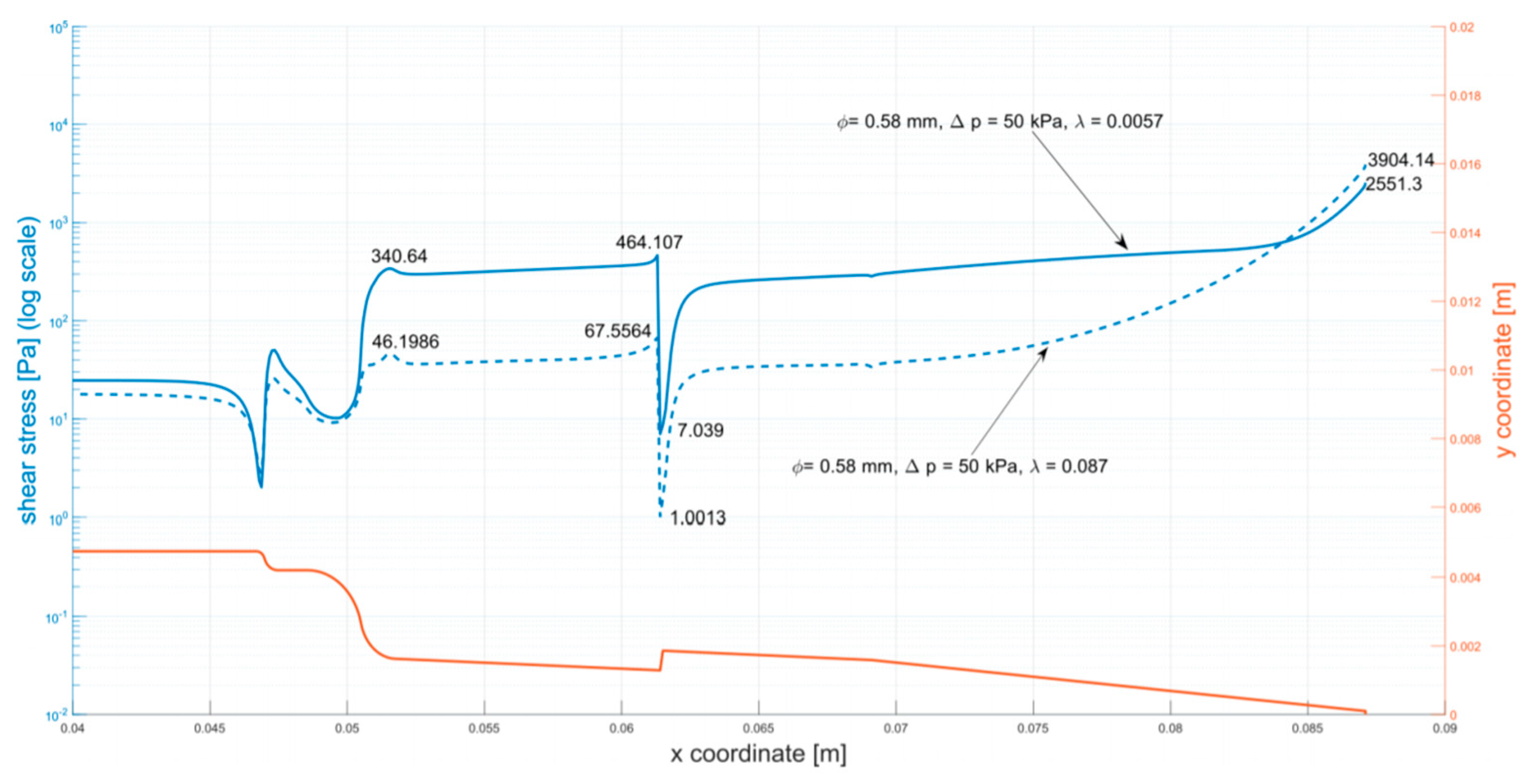
| Diameter (mm) | Pressure (kPa) | Model (λ) | Maximum Shear Stress |
|---|---|---|---|
| 0.2 | 30 kPa | 0.0057 | 1908.86 |
| 0.087 | 3551 | ||
| 50 kPa | 0.0057 | 4107.32 | |
| 0.087 | 5738.6 | ||
| 100 kPa | 0.0057 | 9176.54 | |
| 0.087 | 10694.5 | ||
| 0.58 | 30 kPa | 0.0057 | 1238.97 |
| 0.087 | 2510.6 | ||
| 50 kPa | 0.0057 | 2551.3 | |
| 0.087 | 3904.14 | ||
| 100 kPa | 0.0057 | 5742.28 | |
| 0.087 | 6949.51 |
Publisher’s Note: MDPI stays neutral with regard to jurisdictional claims in published maps and institutional affiliations. |
© 2021 by the authors. Licensee MDPI, Basel, Switzerland. This article is an open access article distributed under the terms and conditions of the Creative Commons Attribution (CC BY) license (http://creativecommons.org/licenses/by/4.0/).
Share and Cite
Klak, M.; Kowalska, P.; Dobrzański, T.; Tymicki, G.; Cywoniuk, P.; Gomółka, M.; Kosowska, K.; Bryniarski, T.; Berman, A.; Dobrzyń, A.; et al. Bionic Organs: Shear Forces Reduce Pancreatic Islet and Mammalian Cell Viability during the Process of 3D Bioprinting. Micromachines 2021, 12, 304. https://doi.org/10.3390/mi12030304
Klak M, Kowalska P, Dobrzański T, Tymicki G, Cywoniuk P, Gomółka M, Kosowska K, Bryniarski T, Berman A, Dobrzyń A, et al. Bionic Organs: Shear Forces Reduce Pancreatic Islet and Mammalian Cell Viability during the Process of 3D Bioprinting. Micromachines. 2021; 12(3):304. https://doi.org/10.3390/mi12030304
Chicago/Turabian StyleKlak, Marta, Patrycja Kowalska, Tomasz Dobrzański, Grzegorz Tymicki, Piotr Cywoniuk, Magdalena Gomółka, Katarzyna Kosowska, Tomasz Bryniarski, Andrzej Berman, Agnieszka Dobrzyń, and et al. 2021. "Bionic Organs: Shear Forces Reduce Pancreatic Islet and Mammalian Cell Viability during the Process of 3D Bioprinting" Micromachines 12, no. 3: 304. https://doi.org/10.3390/mi12030304
APA StyleKlak, M., Kowalska, P., Dobrzański, T., Tymicki, G., Cywoniuk, P., Gomółka, M., Kosowska, K., Bryniarski, T., Berman, A., Dobrzyń, A., Sadowski, W., Górecki, B., & Wszoła, M. (2021). Bionic Organs: Shear Forces Reduce Pancreatic Islet and Mammalian Cell Viability during the Process of 3D Bioprinting. Micromachines, 12(3), 304. https://doi.org/10.3390/mi12030304