Abstract
The exploitation of synthetic aperture properties in nadir-looking radars is opening new scenarios in the framework of satellite radar altimetry. Both recent and upcoming missions including Cryosat-2, Sentinel-3, Sentinel-6 and SWOT take benefit from the coherent processing of radar data, aimed at improving range measurements in particular contexts, such as ice, open ocean, coastal zone, and even inland waters. This work investigates the possibilities offered by current and future satellite radar altimetry missions for the study of inland water bodies, probing into the peculiarities of the expected radar returns and their potential usage. In this regard, signals collected by the RA-2 instrument (Radar Altimeter 2) onboard the Envisat mission offer an unprecedented possibility, even with a relatively low pulse repetition frequency, to analyze the peculiarities of actual signals for detecting and ranging small water surfaces. In particular, the RA-2 instrument offers a global archive of Individual Echoes (IEs), collected at the native sampling rate of 1795 Hz, in addition to the 18 Hz data obtained by incoherent averaging, which are typically delivered to the users as standard products. RA-2 shares with future radar platforms such as Sentinel-6 a continuous and interleaved working modality, as was recommended by the scientific community in designing next missions’ requirements. This is a further reason to consider the usage of RA-2 IEs as particularly attractive. Whilst only available for a small percentage of the earth’s surface, sufficient IE data exist to study the height retrieval capability of these echoes, in particular for what concerns small water bodies, where we show that enough coherence is exhibited for focusing relatively narrow surfaces and range them correctly. A peculiar aspect of this work lies in the assumption that most of the returned echoes (in RA-2 IEs) are specular. A theoretical framework is developed according to this assumption, which is validated by investigating real RA-2 data and observing their related specular features. In particular, we discuss how specular echoes are expected to be very common in inland altimetry, and are most often associated with small to medium size lakes and rivers. This paper illustrates the expected electromagnetic behavior of specular water targets by exploiting the classical radar cross-section (RCS) theory for specular surfaces. Results from the model are compared with real IE data in three selected case studies, regarding two rivers of variable width and one flood plain, in order to check different hydrological regimes. The model very closely matches the data in all cases, making the results of this validation activity very promising. In particular, we demonstrate the feasibility of using satellite radar altimetry in rivers much smaller than what was considered possible until now.
1. Introduction
The Envisat satellite mission, among its several onboard sensors, included a nadir-pointing radar altimeter (RA-2), operating in Ku-band and S-band (the latter being essentially for ionosphere correction). The device was intended by design to downlink pre-processed data (i.e., incoherently averaged) for the extraction of the relevant geophysical parameters in the ground segment. Envisat offered also the option to completely bypass the onboard processing and downlink raw echoes inclusive of the phase information [1]. The RA-2 in its nominal operation mode collected 1795 echoes per second (i.e., one echo every 0.0557 s), however, it averaged over groups of 100 individual echo amplitudes (where phase is discarded) that correspond to a rate of 18 Hz. The resulting data were then transmitted to the ground in packets containing 20 averaged echoes each.
More specifically, the instrument was designed to also provide un-averaged Individual Echoes (IEs) including the phase information, which were grouped in sequences (packets) of 1984 complex echo samples (about 1.114 s at a PRF of 1795 Hz), giving approximately 7 km of ground coverage. These sequences were recorded every 3 min, so only a small proportion of the ground track is sampled in this modality. Such mode of operation was intended for research purposes, and it is proposed in this paper as a way to investigate alternatives to the standard on-board incoherent summing. Although the surface is sampled in a spotted way, some IE packets are consistently collected over small water surfaces. This unique feature offers the possibility to study the characteristics of inland water echoes at an unprecedented level of detail.
Some groups started analyzing these data to see what capability this enhanced spatial sampling might add for the measurement of the heights in small water bodies. The first attempt to investigate IEs is that of Roca et al. [2,3] who analyzed two Envisat passes over the Salar d’Uyuni on the Altiplano of southwestern Bolivia, which is a 10,500 km2 salt lake. Its surface is flat, smooth, and is a specular reflector. The IEs are not noisy (as it normally happens in open ocean) and an amplitude plot reveals the obvious specular structure. More extensive studies were done by Bramer et al. [4], e.g., over a small Amazon tributary where inland water waveforms show more coherent features than their ocean counterparts. Quartly and Passaro [5] made an initial evaluation of IEs over ocean from the SARAL/AltiKa mission. In the conclusions, they state that averaged echoes constructed from just a few IEs can be obtained with a noise level comparable to what was the target at 1 Hz only a decade ago. They also state that IEs are ideal for application across narrow water bodies. Biancamaria et al. [6] show that nadir altimeters can observe a narrow artificial canal (with width below 100 m) using re-tracked SARAL/AltiKa data at 40 Hz and that the target response in the radargram is characterized by high intensity values of the received signal, indicating the typical specular nature of the target. The interest of radar altimetry for hydrological applications is also demonstrated by the joint international effort in developing the SWOT (Surface Water and Ocean Topography) mission, set to launch in 2020 [7].
The aim of this work is to discuss the specular nature of inland waters, with its implications to the processing of the radar returns. In this particular framework, Envisat IE data offer a special opportunity for investigating such specular features. Envisat RA-2, with its continuous and interleaved working mode exhibits enough coherence for Doppler filtering [8]. Moreover, such interleaved working scheme will be offered by future radar platforms for ocean topography applications such as Sentinel-6 (also known as Jason-CS), differently from the current SAR (Synthetic Aperture Radar) missions, such as CryoSat-2 and Sentinel-3, which are based on burst transmissions. In fact, the OSTST (Ocean Surface Topography Science Team) strongly recommended (in its 2012 meeting) that Sentinel-6 altimeter shall deliver LRM (low resolution mode, i.e., conventional altimetry) and SAR mode over all oceans, seamlessly and simultaneously, by implementing a sort of “interleaved mode”. This continuous transmission modality is advantageous also for small specular targets, thanks to the lobing features of their radar returns, which will be demonstrated further in this paper. Thus, the archive of IEs collected by RA-2 offers today a unique opportunity to experiment the potentialities of the coherent processing of radar altimetry data in the observation of surface water bodies.
In particular, this work deals with inland water applications, by discussing the main properties of specular targets, the potentialities of the Doppler processing of the returned echoes, and finally introducing selected case studies, in order to show the possibility to focus and range relatively small water bodies. The paper is organized as follows: Section 2 is focused on the modeling of specular echoes in water targets from a theoretical point of view. Section 3 describes the IE data sets and the processing of specular echoes. Section 4 illustrates the selected case studies of Rio Nahuapa (Peru), River Semliki (Congo) and Prek Toal (Cambodia) flood area. Section 5 discusses the results and provides the main conclusions and future perspectives.
2. Theoretical Model of Specular Returns from Inland Waters
In this section, we describe the synthesis of radar altimetry echoes from water bodies, with reference to small relatively flat (with reference to wavelength domain and incidence angle) inland water surfaces. Quantitative assessments of the radar backscatter for low incidence angles in Ku band have been presented also very recently [9], but their scope is generally limited to the estimation of radar cross-section. Thus, it is now well established that nadir RCS is not very sensitive to surface roughness in the low to moderate wind conditions, but phase and coherence have not been investigated yet. As stated in Section 4 of this paper, the vast majority of the water bodies (usually <300 m in extent) for which we collected IE data, exhibited quasi-specular reflection mechanisms.
The formalism introduced in this section is subsequently used in Section 3 to define algorithms for inland water ranging and water level measurement.
2.1. The Theoretical Complex Radar Altimeter Echo, (n,r)
All current radar altimeters are nadir pointing and ping the Earth at regular intervals. Envisat and other “older generation” radars pinged at about 2 KHz. More recent altimeter systems are using ~20 KHz PRF. The echo of each radar ping is range-gated in all cases.
Figure 1 illustrates a satellite in orbit and the Earth illuminated by a single radar pulse. S0 is the annulus of the range bin at the initial contact, Sr is the annulus of a generic range bin at a further range from nadir. The thickness of an annulus corresponds to one radar range bin.
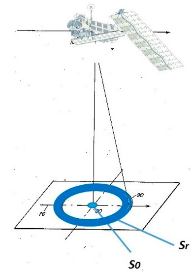
Figure 1.
Range annuli for a single echo. The pattern moves along the satellite’s nadir track line with each successive radar echo.
The radar nadir point sweeps along a ground track. With Envisat’s PRF this means a ping every 3.8 m along the ground track. The successive series of IEs are designated by echo number n.
Let z(n,r) designate the observed nth complex radar echo in the range bin r, corresponding to range annulus Sr. Here, we describe the model that would exactly match an observed z(n,r) if all model assumptions are satisfied. Our model assumptions are the following.
- -
- There is zero reflectivity from land: all reflectivity is from water surfaces.
- -
- Water surfaces are flat: there is no wind roughening.
- -
- The water surface area is known exactly: location and extent.
In this work, we analyze the electromagnetic behavior of the water surface under the stated strong assumptions and we will show that results from practical cases are in good agreement with the expectations, even under the strongest simplifying hypothesis.
At the nth ech,o the radar altimeter is at location , and the range from altimeter to a location on the Earth rigid surface at is , where is the water level with respect to a reference height, and is the unit vector perpendicular to the geoid. The phase of the round trip echo from one specular elemental scatterer at this location is . The complete complex return z(n,r) is a sum of elemental scatterers within the radar footprint (Kerr, 1951), weighted appropriately by the radar’s range point spread function. The model for z(n,r) is thus:
where, is the radar range bin width; is a map of the Earth surface, having a value of 1 where there is water, and 0 otherwise; and is the radar wavelength.
There are three terms within the area integral. The is the complex radar echo of one elemental surface, with a phase shift due to the round trip distance between radar and surface. The limits the integration to the scatterers within the physical boundaries of water surfaces. The sin(x)/x term is the radar in-range response, weighing each elemental scatterer according to the distance from the range bin center.
The average weight on a scatterer located within the rth annulus is the result of integrating the power in Equation (1) in the interval [−1/2…1/2] about the bin center. For scatterers that physically fall in the adjacent range bin (adjacent annulus) the average weight is lower but not negligible; two bins away it is expected to be even lower, and so forth. In fact, there is a significant echo power leaking into a range bin from outside the Sr annulus. This fact turns out to be surprisingly beneficial, because it enables sub-range bin resolution in the water level assessment, and this is made possible by a simple algorithm. For completeness, Equation (1) should also include the antenna beam response function. In all practical cases that will be considered in the paper, the water body is at or very near nadir, with a maximum off-nadir angle <0.1°. Thus, the beam term has been left out, given that the Envisat beamwidth is 1.29°.
It may be of interest to some readers to compare this model with the well-known Brownian [10] radar altimeter model. The Brown formula has been used for three decades of sea-level measurements. At the core the two models start with the same basic physics, i.e., summing flat elemental scatterers. Neither has wind surface roughening. The Brown model incorporates wind roughening only as a constant sigma-0 for all scatterers. One significant and meaningful difference is that here water is flat,, whereas over ocean has the distribution of wave height (the Brown model, however, can be “dialed” down to a flat ocean). Another difference is that the ocean is boundless (at least for Brown’s theory) whereas here we look at bounded water surfaces such as lakes and rivers. A very important difference is that in our model we retain the phase information, which can be useful if multiple echoes are combined coherently. Brown did not envision coherence between successive echoes. In fact, the PRF of early radar altimeters was specifically chosen to minimize inter-echo coherence [11]. However, on inland waters there is inter-echo coherence even with low PRF (such as Envisat) and the coherence can be exploited. This is a favorable condition for the altimeter Poseidon-4, which will be onboard the Sentinel-6 mission, with its medium PRF of 9200 Hz.
The integration in Equation (1) is implemented with the Earth map M discretized into square dS cells. The computation time goes as 1/dS2. We verified the numerical accuracy of Equation (1) on simple geometric shapes to reproduce the classic and well know RCS patterns, e.g., the thin rectangular plate [12]. With Envisat parameters we found that 1 m × 1 m cells provide sufficient accuracy. There is no discernable change with smaller cells; 2 m × 2 m cells begin showing discernable noise in the second and third sidelobes. The model is computationally intensive but we experienced 10× or more acceleration with GPUs.
2.2. The Spatial Extent of Specular Echoes and Its Implications
The spatial extent of radar echoes can be generally thought as infinite, but, for practical purposes, it is mostly limited to the radiator’s main lobe, where the illuminated target is treated as a radiator. In general, the size of the main lobe first decreases with the increasing size of the water target, in a similar fashion to the law of the radiation pattern of an aperture antenna. Then, at some point, the relationship reverses and the lobe width increases with the size of the target. Given the parameters in Table 1, Equation (1) was exercised for a range of target widths in order to identify where such transition occurs. Figure 2 shows a turning point at about 100 m in size of the target, assuming the main lobe width at 10 dB below peak. Consequently, very narrow rivers can be characterized by main lobes that are much wider than the river itself, and inversely proportional to the river width. Instead, water bodies with a spatial extent (along track) higher than 100 m are expected to produce a strong echo for a duration that coincides with the track crossing the water. A deeper analysis of this behavior falls outside the scope of this paper, and it is the intention of the authors to develop a dedicated work for probing further into this aspect and its implications.

Table 1.
Relevant parameters characterizing the Envisat collection of Individual Echoes.
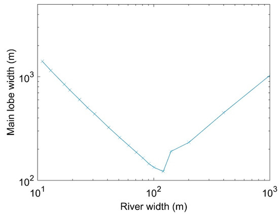
Figure 2.
Main lobe width (at 10 dB below peak) as a function of river width.
The examples discussed in the next two sections hint at the said two conditions. In Section 2.3, we discuss the behavior of water bodies smaller than 100 m. It is shown that the width of the main lobe is inversely proportional to the physical size of the water surface. In Section 2.4, we discuss larger water bodies, where the spatial scale is proportional to the size of the water body. A possible practical implication for the analysis of a wide range of inland waters is to assume a main lobe width of at least 100 m, or 26 IEs, which will fit the true behavior of the radiator, in most cases.
2.3. Very Small Water Bodies
The smallest possible target is a point specular target. The integral in Equation (1) is eliminated since the radar echo is from only one elemental scatterer. The echo power is constant for the duration the target is within the antenna beamwidth. The target does not even have to be near nadir. In the (n,r) plane, all the energy falls on a hyperbola manifold [13,14,15]. It is not uncommon to see such hyperbolic patterns in radar altimeter data, especially from small vessels near coast. Egido and Smith [16] give a further example of the CryoSat-2 radar pass over the Svalbard transponder, which was designed as a point scatterer calibration for radar altimeters. Figure 3 in the Egido and Smith paper is the for a point specular target.
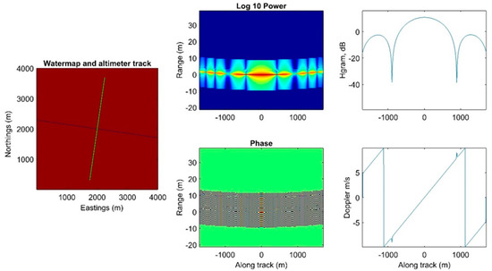
Figure 3.
Model for the narrow river example (dimension is approximately 10 m).
Figure 3 shows the results from the model calculated for a 10 m river. The river is orthogonal to the satellite ground track, straight and 10 m wide (blue line in the left panel). The white line is the nadir track. The center panel shows the power and phase of a complex radar echo obtained by the model. Here and elsewhere in this paper, the echo number n is replaced with the equivalent distance of the satellite nadir from the water centerline (along track distance); to convert to echo number, simply divide the distance by 3.8 m. This makes more apparent the relatively short distance at which water can be detected before or after the satellite nadir passes over the water surface. The range dimension is plotted as range in meters relative to local Earth ellipsoid, after de-spinning the phase of z(n,r) for the component of the satellite velocity perpendicular to the ellipsoid.
The 10 m river is very similar to a point specular target, except that the echo power is lobed and extends ±1000 m centered on the closest point of approach (CPA). Figure 3, right panel upper plot, shows the maximum power for each received waveform. For a point specular the main lobe extends to infinity. The bottom right panel is the scaled to Doppler velocity in units of m/s. As expected, the Doppler velocity is negative on approaching the first river shoreline. It is positive on receding from the farther shoreline.
2.4. Model Examples for Larger Water Bodies
Figure 4 illustrates the results from the model calculated for the “square lake” case. The left panel is the Earth map, with an isolated 200 m × 200 m lake in the center (blue square). The central panel shows that the model output is not a hyperbola. There is a 200 m stretch over the water surface where the range is constant. The hyperbola-like range migration exists only when the nadir point is either approaching or receding the lake shoreline. In essence the hyperbola is flattened at the center.
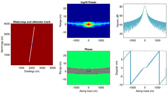
Figure 4.
Model for the square lake example (dimensions are approximately 200 m × 200 m).
The top central panel is echo power with respect to the along track nadir. The complex echoes are coherently summed over range. It can be seen that the echo power is near constant for the over-water duration and drops precipitously when the radar nadir is just beyond the shorelines. More importantly, the Doppler rests at zero for the over-water duration.
Figure 5 shows the model results for a “peanut-shaped” lake, which has similar size to the square lake, but with an irregular shape. In addition, the lake center has been displaced from the nadir track. The point of this example is to illustrate the important characteristics that are peculiar to realistic water surfaces, i.e., the flat topped amplitude and the zero Doppler velocity during an interval around the CPA, as it is obtained also in this case.
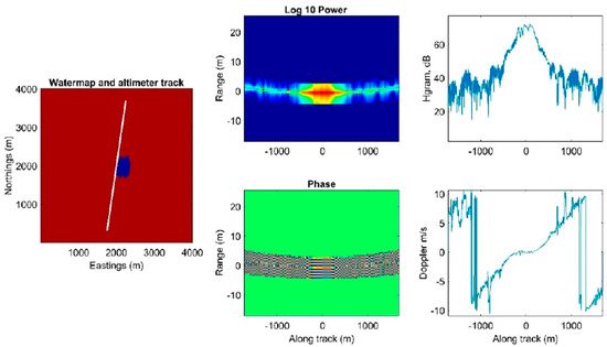
Figure 5.
Model for the peanut-shaped lake example. Power at CPA is about 70 dB.
3. Range Determination for a Specular Target
The purpose of this section is to define algorithms for inland water ranging and level measurements. There will be a rigorous but computationally expensive algorithm (Section 3.1) and another greatly simplified method (Section 3.2) that performs almost as well. In Section 4, the theoretical prediction is compared with real world data to investigate the possibility to identify and range real inland water bodies according to our approach.
3.1. Phase-Focused Method
Egido and Smith [16] discussed the SAR focused on point targets. Here we extend the idea to a generic water body of any shape and size by defining the following cost function (CF1):
where the variable is again the water level. There are two possible ways to describe this equation: one way is to see it as a phase unwinding function, which rotates each vector z to zero phase, before stacking them; another way is to describe it as a matched filter of data z with model. The water level is solved by finding the value of that maximizes the match.
The upper plot in Figure 6 is the CF1 for the peanut lake example. The data were simulated for a lake level of 17 cm. CF1 was computed for a range of levels from −25 cm to +65 cm. The cost function peaks sharply at the correct level, which was simulated as 17 cm.
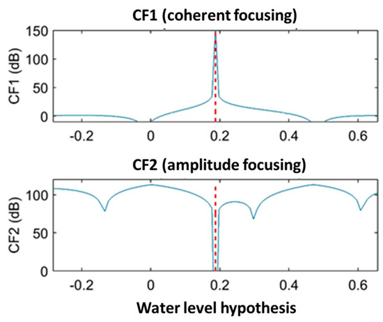
Figure 6.
Calculation of the two cost functions described in Section 3.1 for the peanut-shaped lake example.
It is not yet known if the computation required by CF1 is justifiable given the assumptions in the modeling. For example, the model needs map M as an input. Conceivably the map may come from water mapping with optical images. The Sentinel 2A/B constellation, for example, can provide in theory a worldwide water map at five-day intervals (excluding clouds). However, the water boundaries may not be known as precisely if optical and altimeter passages are not simultaneous.
Another suitable cost function (CF2) may be defined as follows:
CF2 discards the phase information, relying only on the echo amplitudes. The optimum water level is the one that minimizes the amplitude difference. The cost function is shown in the bottom panel of Figure 6. The absolute minimum finds the correct water level, 17 cm. The solution is only slightly less peaked than the coherent focus.
There is no appreciable saving in computational time. The main advantage of CF2 is that it leads to a much simplified algorithm, which needs much less reliance on accurate water maps. In the next section a simple algorithm that mimic CF2 with very few computations is described.
3.2. Simplified Algorithm
Our simplified approach begins with the recognition that significant echo power is limited to an optimum duration. For a narrow water body (<100 m), the duration is half the main lobe. For a wide water body (>100 m), the duration is the width of the water body. The 100 m breakpoint was explained in Section 2.2. There is little value in including data beyond the recommended duration, because the echo has likely fallen into the noise. In addition, going further from the intended water center, the chance of encountering interference from another scatterer or another water body increases.
It will be shown in Section 3.2.3 that, in our proposed approach, the water level is estimated by a least-squares fitting to the echo power in two or three range bins. However, before this fitting a burst of echoes are coherently summed. Coherent summing increases the SNR with respect to background noise and possible interference. Interference could be from a nearby water body, a natural land feature or even some artificial structure. Interference rejection was introduced in our earlier paper [8] as the “zero Doppler algorithm” (zero Doppler means that the echoes were de-spun for the expected Doppler and summed).
The coherent summing is performed on a moving window of 25 echoes, which is approximately 100 m track length over the Earth surface. This is because all water bodies, narrow and wide, have significant echoes strength for an equivalent length of at least 100 m, as discussed in Section 2.2. This alleviates the need to know exactly the water body size and location.
The coherent sum is defined as:
where is the phase shift on the k-th sample required to align it in phase with the other echoes. The sum is over a burst centered on echo n, k = n − 12, …, n + 12. Over the relatively short time of a burst, we can assume a constant Doppler frequency, and use the following equation:
The optimum coherent burst is centered on the midpoint in the lake or river. The midpoint may be established from overlaying the nadir track on a map or a satellite image. In addition to, or as an alternative, the midpoint can be identified by the zero crossing of the Doppler velocity.
For comparison, the incoherent sum, which is defined as follows:
is also useful for analysis. The standard processing approach (that is generally called “Low Resolution Mode” or LRM) for inland waters uses incoherent summing, as mentioned in Section 1.
3.2.1. Doppler Velocity Estimation
There are several options for the Doppler velocity estimation needed in coherent summing. The simplest, as previously discussed, is based on the fact that the Doppler is very close to zero in the optimum duration, and in fact exactly zero over a wide river. In this case, it is possible to sum the echoes, eliminating the term. A second option is by geometrical consideration of the satellite’s location at each echo with respect to the water centerline. If neither of the above is applicable, the third option is estimating the Doppler from the same data. Here, we propose the usage of the Fitz [17] algorithm:
with the same 2K + 1 burst sum as before. J is the number of lags used in the estimate. For J = 1, Fitz is identical to the well-known frequency estimator based on the phase change between consecutive complex samples [18,19]. The Fitz formula with more lags provides more accurate Doppler estimation. Figure 7 shows examples of altimeter passes over a small river in Peru (Rio Nahuapa), discussed later in Section 4. The picture shows the Doppler estimate with J = 1 compared with J = 5. The plot points represent the Doppler velocities obtained by a moving window comprising 25 echoes. The Doppler velocity varies gradually, with Doppler = 0 corresponding to the river centerline (as it is confirmed by the overlay of the data on Google Earth images). Further details on the Fitz method are in Appendix A. Five-lag Fitz (panel b in Figure 7) is significantly better than its 1-lag counterpart (panel a). The improvement is most noticeable further from the river centerline, where the echo power has dropped 15–20 dB from the central peak.
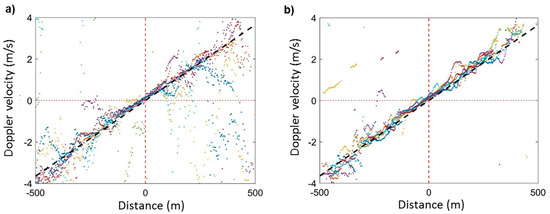
Figure 7.
(a) Doppler velocity estimation for J = 1 lag; and (b) Doppler velocity estimation for J = 5 lags.
3.2.2. Coherence Estimation
Coherent summing only makes sense if there is significant coherence between echoes. The coherence in the burst of 2K + 1 echoes should be checked as a preliminary step. We employed two types of coherence measurements and found both equally useful. The first one measures coherence between echoes, with a lag of m echoes. This is called the m-lag magnitude squared coherence (MSC) metric and is defined as follows:
where again the sums are over the 2K + 1 burst. The 1-lag is used in subsequent references to the MSC, but higher lags can be used in more demanding tests for coherency.
Another coherence metric is defined between the echo data and the predicted Doppler:
Both metrics result in values between 0 and 1, with values >0.8 indicating very high coherence. In the examples shown in this paper the typical MSC is >0.95 in the main lobe. In near sidelobes we measured still significant levels of 0.7–0.8.
3.2.3. Water Level
In this section, we describe our proposed approach to complete the process for estimating the water level. First, we start with a moving 25-echo coherent summation as described above. Then, we choose a particular echo index, n, corresponding to the CPA. The corresponding range waveform is Pr (the n subscript is now discarded). A first approximation of the water level would be the range bin corresponding to the maximum of the echo power. In terms of mere quantization error, this would provide water level estimations with 14 cm, given the Envisat range gate width (RGW) about 0.47 m (Table 1). However, a much more accurate estimate is made possible by interpolating the peak samples. In particular, later in this paper, we will show rmse < 1 cm with real world data.
The expected range waveform for a specular echo can be approximated with a Gaussian function as follows (modified from Garcia et al. [20], Equation (2)):
with standard deviation where is the effective pulse length.
This approximation is only valid at or near nadir; therefore, it is supposed to be sufficient within the span of the main lobe. The approximation should not be used to range water bodies located very far off the nadir (but that is not likely since the specular echo will not be detected anyway).
In general, the interpolated range and the peak power P0 are found by minimizing the following cost function:
where the sum is intended as limited to those waveform samples having significant power originated by the specular reflection; the rest are either noise or interference and should be avoided. In typical RA-2 signals, a specular echo extends over at most three range bins. In practice, two of the three are so much stronger than the third that the usage of only the two str ongest range bins, and either or , can be sufficient for the assessment of .
With only two bins, the solution for range is simplified to the following:
where and is the corresponding range bin.
It is important to notice that Equation (12) represents an analytical solution in closed form, unlike what commonly happens with altimetry waveforms, generally requiring some form of fitting or “retracking” exercise.
Figure 8 is an example of a specular waveform from Envisat crossing over Rio Nahuapa (further discussed in Section 4.2) with coherent burst summing (Equation (5)) of 25 echoes. The example has been extracted from the dataset described in Section 4.1. The overlaid curve in Figure 8 is the best fit of Equation (10) to the data. There is a near perfect fit to all three top range bins, although only the highest two were used in the fitting. The interpolated range is approximately half way between bins 2 and 3.
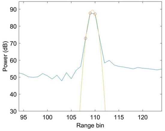
Figure 8.
Example of two-bin range solution.
4. Selected Case Studies
In this section, we describe real-world water bodies from three different locations, and we check their behavior with respect to our model expectations. Specular features are expected to be very common in unaveraged raw waveforms from inland altimetry, and most often associated with small size lakes and rivers. We examined ~30 locations world-wide where the IE data base had multiple altimeter passes over water bodies, usually <300 m in extent. Three locations were chosen as representative cases for this paper, but most of the other cases were similarly specular. Case studies from very different contexts have been chosen, in order to show how this deduction can be generalized.
The first case study is the 45–65 m wide Rio Nahuapa (Peru), which provides 3 crossings of the satellite track within the same IE packet, offering a simple and straightforward proof of specular water reflection in agreement with model calculations. The width of the RCS (radar cross-section) main lobe varies with the width of the river. The relative levels of side lobes with respect to the main lobe also change with the river width. Second is the 150 m wide River Semliki (Congo), useful to extend the proof of the specular model to a wider river. In addition, in this case, data are consistent with the model prediction. Third is the Prek Toal flood area (Cambodia), which approximates an “infinitely” wide reflecting surface. At maximum flood the water extent is >100 km, which for the purpose of the model calculation can be thought as “infinite”. This is the opposite of point specular targets that produce the hyperbola radargram. In the “infinite” case, the theory predicts that all the echo power is in the first contact range bin. The data are consistent with this expectation.
4.1. Description of the Dataset
The Envisat IEs have been reprocessed by ESA, using the RAIES processor [21] and delivered as L1B products. One L1B file is a collection of all IE bursts recorded in one satellite orbit (or pass). One IE record consists of a 2D array of complex values, containing both in-phase (I) and quadrature (Q) components of a complex signal z(n, r) = I + jQ , indexed by (n, r), where n = 1, …,1984 denotes the pulse number along the satellite track and r = 1, …, 128 is the index of the concentric range annuli. A collection of L1B files has been provided by the European Space Agency, and all the data made available by ESA are now catalogued on disk. The available IE data cover all sorts of water targets, including open ocean, coastal zone and inland water. For the purpose of this paper, the attention has been concentrated on inland water targets.
4.2. Rio Nahuapa
The first demonstration is Rio Nahuapa, a tributary of Rio Tigre, Peru. Rio Nahuapa flows south, but meanders back and forth E-W so that an altimeter nadir track is likely to intersect the river at multiple points (Figure 9). In particular, the data that we analyzed are characterized by three crossings. The North-most (upriver) intersection is labeled “Crossing 1” (4.39° S, 74.11° W). The next two at intervals of 4–6 km downstream along the meandering river are named “Crossing 2” and “Crossing 3”.
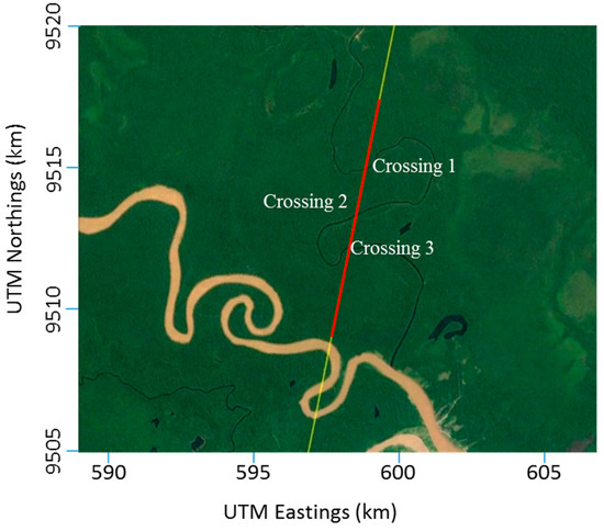
Figure 9.
Rio Nahuapa and Envisat Nominal track (IE coverage highlighted in red).
The river width increases from about 45 m at Crossing 1 to about 65 m at Crossing 3. The altimeter track cuts almost perpendicular to the river direction, simplifying the interpretation of the echo time series. Rio Tigre, which is 300 m wide in this location, is just beyond the point where the tracks terminate after Crossing 3. Envisat tracks repeat every 35 days. We have data from eight passes in the period 2007–2008.
Figure 10 is the radargram from one of the eight passes (they are all very similar). The radargram has three striking flashes of specular returns corresponding to the three river crossings. The altimeter track never quite reaches Rio Tigre but some off-nadir returns from Rio Tigre are presumably seen at the far right.
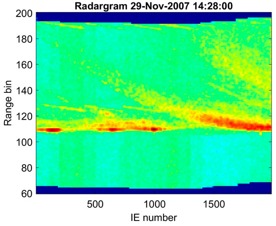
Figure 10.
Radargram for the Rio Nahuapa case.
Preprocessing on the data includes correction for the onboard tracker, which causes the jagged top and bottom edges. AGC adjustments are made so that echo power is on a consistent scale and comparable across all the examples. In L1B data the Doppler includes the satellite vertical velocity. This vertical velocity is known from satellite ephemerids; phases are accordingly adjusted to facilitate comparison with theoretical model expectation that Doppler is zero at CPA. It can be observed that there is only a slight mark of echo power on the hyperbola. This is because the side-lobes quickly drop >30 dB from the peak and into the background noise. Echoes from Rio Tigre begin to be detected further on a quasi-hyperbola (IE numbers > 1300, approximately).
In Figure 11 the eight radargrams have been collapsed to a 1-dimension peak power plot, and mapped on a Google Earth image. Successive radar altimeter passes drift in longitude; interestingly, the effect of many passes over the area is to paint a map of the water surface.
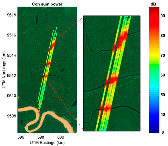
Figure 11.
Amplitude profiles of the 8 passes used in this case study (Rio Nahuapa).
The results presented in Figure 11 show how the main lobes scale with the river width, being narrower the lobes pertaining to the wider river sections. In particular, Figure 12 shows the RCSs for Crossing 2 (left panel) and 3 (right panel). Coherently integrated bursts of 21 echoes were used to produce the plots. Each of the eight passes is a plotted with a different color. The dashed black curve is the theoretical power returned for 45 m and 65 m wide rivers, respectively. The widths were estimated from Google Earth, with an accuracy estimated as ±5 m. The distance is from the river centerline. All passes are remarkably similar. Their power levels cluster in a narrow range 88 ± 2 db. There is excellent agreement in both the width of the main lobe and the level of the first two or three side lobes. Crossing 2 can only be plotted on a distance interval of ±500 m before encountering side lobes of crossing 1 and 3. Crossing 3 can be plotted a bit further out, to 800 m, and shows a remarkable agreement between data and theory up to the 5th side lobe and a power range of 20 dB.
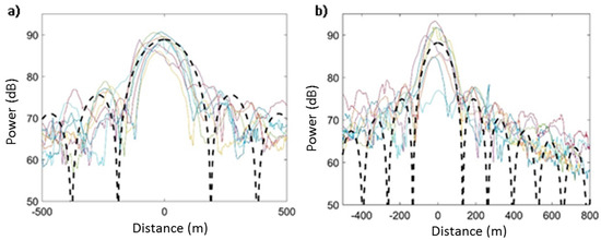
Figure 12.
(a) RCSs and model RCS for Crossing 2, 45-m wide; (b) RCSs and model RCS for Crossing 3, 65-m wide.
Figure 13 illustrates the ranging with the two-range-bins method described in Section 3.2.3 (Equation (12)) for Crossing 2. The abscissa is the same as in Figure 12. The left panel are range solutions with single echoes. The right panel presents the range solutions obtained with coherent burst integrations.
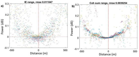
Figure 13.
(a) Range estimates with raw IEs; (b) Range estimates with coherently integrated bursts of IEs.
Coherent integration visibly improved the range estimates. For range estimates within the main lobe, the improvement is from rmse 1.1 cm with Individual Echoes to 0.4 cm with burst integration. Here the rmse is intended as an estimator of the measurement noise, and is inferred from sample to sample difference. It is noteworthy that 0.4 cm is 1/100 of a range bin. More significant improvement is even made in the side lobes.
The sub-cm accuracy can be useful for estimating the river slope. In Figure 14c is the range estimated on the three crossings over Rio Nahuapa, where the range increases with the river flowing down to meet Rio Tigre. Under the hypothesis of constant geoid slope over the three crossings, the level drop from the first to the last crossing would be 16.4 cm (about 0.35 range bins, corresponding to 16.4 cm with RA-2 parameters), over a run length of the river that is approximately measured in 11.3 km by satellite images. The dashed horizontal lines in Figure 14c clarify the level estimation in terms of fraction of range bin, after applying Equation (12). The average river slope is therefore 1.45 cm/km. The slope is in the right direction as it is known that Rio Nahuapa is flowing down to its confluence with Rio Tigre.
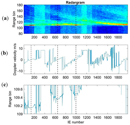
Figure 14.
River slope estimate in: (a) radargram; (b) Doppler velocity; (c) range bins.
4.3. Semliki River
The second demonstration regards the Semliki River (Congo, central Africa). There are seven passes with RA-2 IE data available, over the Semliki River (0.136°S, 29.582°E). The altimeter tracks cross the river just 2 km from its mouth on Lake Edward, close to the Congo, Uganda border. Semliki flushes water out of Lake Edwards, to Lake Albert which is about 150 km north. Figure 15 shows the seven altimeter passes crossing the river. The river is approximately 150 m wide at this point. Despite the much larger size of this river (compared to Rio Nahuapa) the echoes appear to be specular in every pass. The tracks start just before the river, come into the radar view and continue after a brief run over land into Lake Edward, which (interestingly) does not exhibit any specular return, as expected by its dimensions and the resulting surface roughness.
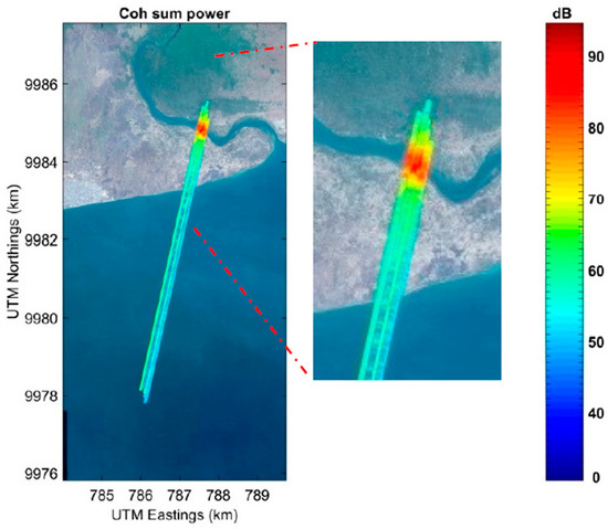
Figure 15.
Seven altimeter passes crossing the river. Color bar indicates the power of the returned echoes (coherently summed).
Figure 16 plots the waveform of echoes over the river, and for comparison an overlay of the lake waveform. The river has a strong specular component with a weak underlying Brownian waveform, while the lake exhibits a classical Brownian waveform. The Brownian waveform implies that the lake surface is rough, which is not surprising since Lake Edward is large enough to produce “ocean-like” wind waves. The small peak on the leading edge of the Brown waveform, at range bin 109, can be presumably due to a small vessel on the lake. In any case, its hyperbolic feature in the radargram (not shown) represents the classical peculiarity of a point-like structure.
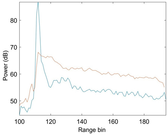
Figure 16.
Specular waveform of Semliki echoes (blue), compared with the Brownian Edward Lake (red).
The theoretical RCS (dashed black) overlaid on the seven altimeter passes is illustrated in Figure 17, highlighting a good agreement between theory and data as expected. Compared to the case study of Nahuapa River, the RCS narrows in Semliki River. In Nahuapa the side lobe at 500 m distance is 20 dB down from the peak. At the same distance in Semliki the side lobe is down 30 dB. This difference is explained by the nature of specular returns as discussed in Section 2.2. In addition, Figure 18 shows a good agreement of the theoretical Doppler velocity with the data. It is especially noteworthy that theory inferred from Equation (1) predicts the Doppler leveling to zero when the altimeter is directly over the water and this is confirmed by the collected data.
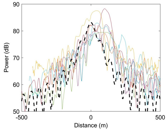
Figure 17.
Theoretical RCS (dashed black) overlaid on the seven altimeter passes. Different colors are used to distinguish between the different satellite passages.
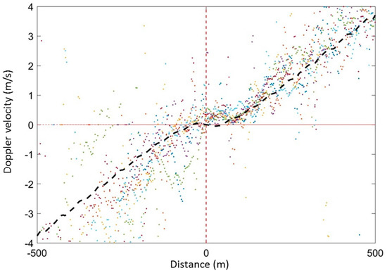
Figure 18.
Doppler velocity from River Semiliki; dashed line is the theoretical Doppler. Different colors are used to distinguish between the different satellite passages.
4.4. Prek Toal Flood Area
Prek Toal (13.1°N, 103.6°E) is on the NW corner of the famous Cambodian lake, Tonle Sap. The area undergoes an annual inundation cycle as the lake rises ~7 m from May to peak flooding in November. There are seven IE recorded passes, spanning May–December 2007, recording water rise from minimum to maximum.
There are also three published works [22,23,24] with extensive in situ, MODIS, and InSAR observations in exactly the same area, and in the same time period. Choi et al. [22] include a graph of 18-Hz Envisat RA-2 water levels (see their Figure 5). They attribute this data coming from EAPRS Laboratory and Jerome Benveniste (personal communication). The quoted measurements corresponding to our seven IE data records are reported in Table 2.

Table 2.
Tonle Sap levels (m) in Choi et al. [22] corresponding to the seven IE passages available for this study.
The IEs behavior shows how the specular features (easily identified by the echo power) are in accordance with the water levels from Table 2. In general, satellite passes show a nearly continuous quasi-specular and flat surface level, but echo amplitudes are very different. In the May, July, and August data, the peak echo power is in the 50–70 dB range, and the peak in MSC is <0.5. There are specular echoes, but intermittent and unremarkable. In the subsequent four passes, September, October, November, and December, the peak echo power increases by 30 dB, and the peak in MSC is >0.8. According to Choi et al. [22], which refers to Benveniste, water level rose from the 6.7 m to 9.1 m level between August and September. That rise appears to have inundated the entire area covered by the IE tracks.
Figure 19 (upper panel) is the radargram related to the pass on September 12, which shows an almost continuous 80 dB echo strength at nadir. The strongest echo is indicated by the dashed vertical line. The waveform for this echo is plotted on the bottom panel of Figure 19. This is the waveform corresponding to the strongest IE over the 128 range bins (here offset by 64). The intent is to show the narrow range of the specular echoes, with peaks of 80 and 100 dB over a background of about 50 dB. The coherent burst integration is 20 dB greater than incoherent integration, proving benefit of coherent integration, applicable in the case of high coherence between IEs. Three variants of the waveform are shown. The waveform of an individual echo peaks at 80 dB with a noisy floor at off nadir ranges. The incoherent burst integrated power is also 80 dB. In the range bins before the first contact the noise floor level is about 50 dB. The coherent burst integration peak is 100 dB, a 20 dB gain from coherent integration. All these results are consistent and expected for specular echoes.
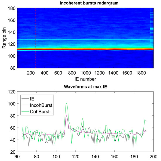
Figure 19.
Radargram related to 12 September (upper plot) and waveforms corresponding to the strongest echo (lower plot) for IE (black), incoherent burst (cyan) and coherent burst (green).
The two-bin range estimation method (described in Section 3.2.3) was applied to the entire length, using coherent bursts of 100 echoes. For each range estimate a corresponding coherence was calculated by Equation (8). A threshold of 0.7 was set on the MSC, in order to select the best measurements and reject noisier measurements. Figure 20 shows the water level (relative to an arbitrary reference level) for the four final dates. The gaps are locations where coherence was below threshold. There is a consistently repeated 1 cm/km trend over the four dates.
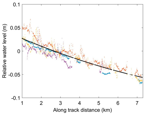
Figure 20.
Along-track relative water level (m) from four IE passes taken over Prek Toal during the flood season.
It was suggested that the trend reflects a geoidal height variation (Walter H. Smith, private communication), estimating a down-slope 3 cm/km based on the EGM2008 and EGM1996 geoidal deformation models. However, our data derived from altimetry indicate 1 cm/km. This suggests the possibility to make use of altimetry on flood plains for cross-validating with geoid assessments.
5. Discussion and Concluding Remarks
Envisat collected 1-s bursts of 1984 × 128 range bins of IE complex echo returns every 3 min. The available IE data cover all sorts of water targets, including open ocean, coastal zone and inland water. A systematic study of global echoes, although not yet exhaustive, shows a generalized specular behavior in most small and medium inland water targets across the world. This paper illustrates the expected electromagnetic behavior of inland water targets by exploiting the classical radar cross-section (RCS) theory for specular surfaces. Results coming from the theory are compared with those from real IE data, collected by the Envisat satellite in three selected different case studies regarding inland water targets chosen in different contexts.
Over the floodplain of Prek Toal, the Envisat altimeter behaved reasonably well. The most interesting result was the capability to identify a gradient during full flood. In fact, the untracked radargrams showed the expected steady sloping valley floor in the northern direction, with a noticeable difference in amplitude between the dry season and the flood season. The Prek Toal case demonstrates the use of specular echoes to measure levels of flood areas as well as appreciate small geoidal corrections as a bonus.
The two case studies (Section 4.2 and Section 4.3) involving rivers demonstrate the potential of specular echoes to measure river levels, but also point out that this is possible only for rivers at or very close to nadir. The waveforms collected in the Lake Edwards vary from weak to moderate Brownian, while the river Semliki is always specular. Rio Nahuapa is a much narrower river than Semliki, and the satellite track makes multiple crossings of the river, providing new insights into the detectability of small rivers. The results are promising because they demonstrate the feasibility of using satellite radar altimetry in rivers much smaller than what was considered possible until now.
The echo power is accurately described by the RCS model. The model very closely matches the data. The width of the main lobe, the position of the side-lobes, and the 20 dB difference between main and side lobes, are all consistent with the data. These findings indicate that most rivers can be modeled with the RCS of a specular surface. The most interesting results of this work can be resumed as follows: (1) specular echoes are coherent for many independent echoes; (2) specular echoes have a well defined Doppler evolution and can be SAR processed for water level estimation, avoiding any classical retracking; and (3) there is a relationship between target size and lobe size, with very interesting implications to the determination of an optimal burst length, which is an important point for further studies.
The advantage of IEs is that the averaging can be precisely centered on narrow water bodies and can be coherently (zero Doppler) averaged. Coherent averaging further increases the accuracy of the level estimation. The Individual Echoes produced by the Envisat RA-2 platform represent the only currently available dataset for the experimentation of continuous coherent processing on real data, making this dataset extremely important and under-exploited until now. Satellite and radar configurations (PRF, orbit parameters, etc.) can exploit positively the peculiarities of specular echoes, and serve as a basis for the development of future missions. The results of this work may also support a more effective use of the currently available data, in the prospect of building a global inland water level monitoring by satellite observations, inclusive of small size water bodies.
Acknowledgments
The analysis of Envisat IE data has been inspired by the ESA funded COASTALT project that was aimed at exploiting Envisat altimeter data in the coastal zone. The help of several individuals is graciously acknowledged. Salvatore Dinardo of Eumetsat and Jérôme Benveniste of the European Space Agency made possible the access to the IE archive. Roberto Cuccu, Giovanni Sabatino and Jose Manuel Delgado Blasco of the European Space Agency helped in downloading data through the GPOD service. The results in this paper were first reported at the 8th Coastal Altimetry Workshop, Lake Constance, Germany, 23–24 October 2014 (www.coastalt.eu). The authors would also like to thank the four anonymous reviewers for their valuable suggestions and comments to improve the quality of this paper.
Author Contributions
All of the authors listed contributed equally to the work presented in this paper.
Conflicts of Interest
The authors declare no conflict of interest. The founding sponsors had no role in the design of the study; in the collection, analyses, or interpretation of data; in the writing of the manuscript, and in the decision to publish the results.
Abbreviations
The following abbreviations are used in this manuscript:
| AGC | Automatic Gain Control |
| CPA | Closest Point of Approach |
| ESA | European Space Agency |
| GPU | Graphics Processing Unit |
| IE | Individual Echo |
| Jason-CS | Jason Continuity of Service (now Sentinel-6) |
| LRM | Low Resolution Mode |
| MSC | Magnitude Squared Coherence |
| OSTST | Ocean Surface Topography Science Team |
| PRF | Pulse Repetition Frequency |
| RA-2 | Radar Altimeter 2 |
| RAIES | RA-2 Individual Echoes and S-band data for new scientific applications for ocean, coastal, land and ice remote sensing |
| RCS | Radar Cross Section |
| RGW | Range Gate Width |
| SAR | Synthetic Aperture Radar |
| SARAL | Satellite with ARgos and ALtiKa |
| SNR | Signal-to-Noise ratio |
| SWOT | Surface Water and Ocean Topography |
Appendix A. Fitz Doppler Algorithm
Fitz [17] gives a detailed derivation for the maximum likelihood frequency estimation. Here, we provide a simplified but adequate derivation.
Given N complex samples, , the algorithm with 1-lag is:
More generally, one can use the m’th lag [18,19]:
A better estimate is a weighted average of J single-lag frequency estimations:
where is the weight assigned to the m’th lag.
The ML weighting is , where is the variance of the m’th lag frequency estimator. Assuming a pure complex sinusoid + Gaussian white noise (GWN):
Plugging Equations (A2) and (A4) into Equation (A3) leads to exactly the Fitz algorithm (Equation (7) in this paper):
The Fitz paper shows that the algorithm converges on the CRLB in the first few lags. However, as stated in the last paragraph of his paper, “in implementing this algorithm one needs to ensure that”:
The reason is obvious: with one lag, frequencies up to can be estimated. With two lags aliasing starts at , with three lags aliasing starts at , etc. Making matters worse, successively higher lags are weighted more (with m2) so the estimates that are most likely to be aliased are weighted the most.
To deal with aliasing, we modify the original Fitz approach with the following recursive estimation process. We start with an estimate based on 1-lag. That estimate is used to heterodyne the time series closer to zero frequency, in order to avoid aliasing in the next recursion. Each successive recursion adds another lag and further heterodyning.
and so on up to lag J. The final estimate is the weighted average:
The algorithm has been tested using simulations with various SNR in the range of 0.1 to 100,000 (−10 to 50 dB). The algorithm breaks down at SNR < 1 because the first lag does not provide sufficient frequency accuracy to initialize the second lag correctly, and so forth. However, for SNR > 1, there can be a dramatic improvement.
References
- Resti, A.; Benveniste, J.; Roca, M.; Levrini, G. The Envisat Radar Altimeter System (RA-2). ESA Bull. 1999, 98, 8. [Google Scholar]
- Roca, M.; Martínez, D.; Reche, M. Preliminary results obtained using the EnviSat RA-2 individual echoes (full-rate waveforms with phase information). In Proceedings of the IEEE International Geoscience and Remote Sensing Symposium, Seoul, Korea, 25–29 July 2005. [Google Scholar] [CrossRef]
- Roca, M.; Martinez, D.; Reche, M. The RA-2 individual echoes processing description and some scientific results. In Proceedings of the IEEE International Geoscience and Remote Sensing Symposium, Barcelona, Spain, 23–27 July 2007; pp. 3541–3546. [Google Scholar] [CrossRef]
- Bramer, S.M.S.; Berry, P.A.M.; Freeman, J.A.; Rommen, B. Global Analysis of Envisat Ku and S Band Sigma0 Over All Surfaces. In Proceedings of the Envisat Symposium, Montreux, Switzerland, 23–27 April 2007. [Google Scholar]
- Quartly, G.D.; Passaro, M. Initial Examination of AltiKa’s Individual Echoes. Mar. Geod. 2015, 38 (Suppl. S1), 73–85. [Google Scholar] [CrossRef]
- Biancamaria, S.; Frappart, F.; Leleu, A.S.; Marieu, V.; Blumstein, D.; Desjonquères, J.-D.; Boyd, F.; Sottolichioc, A.; Valle-Levinson, A. Satellite radar altimetry water elevations performance over a 200 m wide river: Evaluation over the Garonne River. Adv. Space Res. 2016, in press. [Google Scholar] [CrossRef]
- Fu, L.L.; Alsdorf, D.; Morrow, R.; Rodriguez, E.; Mognard, N. SWOT: The Surface Water and Ocean Topography Mission. Wide-Swath Altimetric Measurement of Water Elevation on Earth; NASA JPL Publication: Pasadena, CA, USA, 2012; Volume 5, p. 228. [Google Scholar]
- Abileah, R.; Gómez-Enri, J.; Scozzari, A.; Vignudelli, S. Coherent ranging with Envisat radar altimeter: A new perspective in analyzing altimeter data using Doppler processing. Remote Sens. Environ. 2013, 139, 271–276. [Google Scholar] [CrossRef]
- Li, X.; Zhang, B.; Mouche, A.; He, Y.; Perrie, W. Ku-Band Sea Surface Radar Backscatter at Low Incidence Angles under Extreme Wind Conditions. Remote Sens. 2017, 9, 474. [Google Scholar] [CrossRef]
- Brown, G. The average impulse response of a rough surface and its applications. IEEE Trans. Antennas Propag. 1977, 25, 67–74. [Google Scholar] [CrossRef]
- Walsh, E.J. Pulse-to-pulse correlation in satellite radar altimeters. Radio Sci. 1982, 17, 786–800. [Google Scholar] [CrossRef]
- Harish, A.R.; Sachidananda, M. Antennas and Wave Propagation; Oxford University Press: Oxford, UK, 2007; p. 411. ISBN 978-0-19-568666-1. [Google Scholar]
- Scozzari, A.; Gómez-Enri, J.; Vignudelli, S.; Soldovieri, F. Understanding target-like signals in coastal altimetry: Experimentation of a tomographic imaging technique. Geophys. Res. Lett. 2012, 39, L02602. [Google Scholar] [CrossRef]
- Gómez-Enri, J.; Vignudelli, S.; Quartly, G.D.; Gommenginger, C.P.; Cipollini, P.; Challenor, P.G.; Benveniste, J. Modeling Envisat RA-2 waveforms in the coastal zone: Case-study of calm water contamination. IEEE Geosci. Remote Sens. Lett. 2010, 7, 474–478. [Google Scholar] [CrossRef]
- Tournadre, J. Signature of lighthouses, ships, and small islands in altimeter waveforms. J. Atmos. Ocean. Technol. 2007, 24, 1143–1149. [Google Scholar] [CrossRef]
- Egido, A.; Smith, W.H. Fully Focused SAR Altimetry: Theory and Applications. IEEE Trans. Geosci. Remote Sens. 2017, 55, 392–406. [Google Scholar] [CrossRef]
- Fitz, M.P. Further results in the fast estimation of a single frequency. IEEE Trans. Commun. 1994, 42, 862–864. [Google Scholar] [CrossRef]
- Rummler, W.D. Introduction of a new estimator for velocity spectral parameters. In Technical Memo; MM-684121-5; Bell Telephone Labs: Whippany, NJ, USA, 1968. [Google Scholar]
- Miller, K.; Rochwarger, M. A covariance approach to spectral moment estimation. IEEE Trans. Inf. Theory 1972, 18, 588–596. [Google Scholar] [CrossRef]
- Garcia, E.S.; Sandwell, D.T.; Smith, W.H. Retracking CryoSat-2, Envisat and Jason-1 radar altimetry waveforms for improved gravity field recovery. Geophys. J. Int. 2014, 196, 1402–1422. [Google Scholar] [CrossRef]
- Haynes, S.; Rogers, C.; le Duc, I. RAIES Individual Echoes Processor. In Technical Specification Report; Ref S & D/SPE/002, 31/07/2007; European Space Agency, ESRIN: Rome, Italy, 2007; p. 105. [Google Scholar]
- Choi, J.H.; Lee, C.W.; Won, J.S. Flood Monitoring in Tonle Sap floodplain using SAR Interferometry. In Proceedings of the 30th Asian Conference on Remote Sensing, Beijing, China, 18–23 October 2009; Asian Association on Remote Sensing: Pathumthani, Thailand, 2009. ISBN 9781615679843. [Google Scholar]
- Choi, J.H.; Van Trung, N.; Won, J.S. Inundation mapping using time series satellite images. In Proceedings of the 3rd International Asia-Pacific Conference on Synthetic Aperture Radar (APSAR), Seoul, Korea, 26–30 September 2011; p. 3. [Google Scholar]
- Van Trung, N.; Choi, J.H.; Won, J.S. A Land Cover Variation Model of Water Level for the Floodplain of Tonle Sap, Cambodia, Derived from ALOS PALSAR and MODIS Data. IEEE J. Sel. Top. Appl. Earth Obs. Remote Sens. 2013, 6, 2238–2253. [Google Scholar] [CrossRef]
© 2017 by the authors. Licensee MDPI, Basel, Switzerland. This article is an open access article distributed under the terms and conditions of the Creative Commons Attribution (CC BY) license (http://creativecommons.org/licenses/by/4.0/).