Highlights
What are the main findings?
- A new “SV2D spectrum” was created to accurately model the complex signal behavior of MEO SAR across the entire scene.
- A novel imaging method using azimuth resampling (NUFFT) and a new focus kernel was proven effective in handling these complex signals.
What are the implications of the main findings?
- This enables high-quality imaging for MEO SAR, which was previously difficult with traditional algorithms.
- The method makes MEO SAR systems more practical by solving key issues like large data volume and severe signal distortions.
Abstract
Although the elevated orbit and highly squinted observation geometry bring advantages for medium-earth-orbit (MEO) synthetic aperture radar (SAR) in applications, they also complicate signal processing. The severe spatial variability of Doppler parameters and large extended range distribution of echo make it challenging for the traditional imaging algorithms to get the expected results. To quantify the variation, a spatially variable two-dimensional (SV2D) spectrum is established in this paper. The sufficient order and spatially variable terms allow it to preserve the features of targets both in the scene center and at the edge. In addition, the huge data volume and incomplete azimuth signals of edge targets, caused by the large range walk when MEO SAR operates in squinted mode, are alleviated by the variable pulse repetition interval (VPRI) technique. Based on this, a novel data-focusing method for highly squinted MEO SAR is proposed. The azimuth resampling, achieved through the non-uniform fast Fourier transform (NUFFT), eliminates the impact of most Doppler parameter space variation. Then, a novel imaging kernel is applied to accomplish target focusing. The spatially variable range cell migration (RCM) is corrected by a similar idea, with Doppler parameter equalization, and an accurate high-order phase filter derived from the SV2D spectrum guarantees that the targets located in the center range gate and the center Doppler time are well focused. For other targets, inspired by the non-linear chirp scaling algorithm (NCSA), the residual spatially variable mismatch is eliminated by a cubic phase filter during the scaling process to achieve sufficient focusing depth. The simulation results are given at the end of this paper and these validate the effectiveness of the method.
1. Introduction
As a microwave-based remote sensing instrument, the medium-earth-orbit (MEO) synthetic aperture radar (SAR) is gradually becoming the development trend for future SAR systems. Generally, MEO satellites are deployed at altitudes ranging from about 2000 km to 35,768 km [1,2], representing a compromise between low-earth-orbit (LEO) SAR and geosynchronous orbit (GEO) SAR systems. Compared with LEO SAR systems, MEO SAR benefits from its higher orbit and squinted working mode, offering wider coverage [3] and a shorter revisit period [4,5,6]. Meanwhile, compared with GEO SAR systems, MEO SAR has more acceptable launch costs and spatial resolution [7,8,9]. Furthermore, the relatively lower orbit provides a higher signal-to-noise ratio (SNR) to the MEO SAR system than the GEO SAR. These conditions offer great advantages for the MEO SAR system in deformation monitoring, ocean sensing, soil moisture estimation, sea ice monitoring, and other similar applications.
However, the more complex geometry of the MEO SAR system aggravates the difficulty of signal processing. To realize a continuous observation ability, the MEO SAR usually works in the squinted mode. The highly squinted angle results in a large range walk spanning hundreds of kilometers, significantly extending the signal’s range distribution. This significantly increases the data storage burden and reduces processing efficiency. Moreover, excessive range walk causes the echoes of edge targets to fall outside the receiving window, thereby restricting the scene size. Another challenge is the severe spatial variability of Doppler parameters caused by the curved satellite trajectory and earth rotation. The traditional assumption of a linear time-invariant (LTI) system is untenable in this situation, meaning that the space-variant term in the Doppler phase cannot be neglected.
The technology of variable pulse repetition interval (VPRI) [10] is a common approach to reduce the dispersion range of the echo caused by a large range walk. By continuously varying the azimuth sampling interval of the SAR system, the variation of the double distance delay between two echoes is converted into the pulse repetition interval (PRI), allowing each received signal to have the same location in the receiving window. The range cell migration (RCM) of the scene center target is removed entirely, and the energy range distribution of other targets can be reduced substantially in this condition.
A spatially variable two-dimensional (SV2D) spectrum is established at the beginning to quantify the space variance of the Doppler parameters. The high-order terms among the SV2D spectrum ensure sufficient accuracy for the single target with a long integration time, and the spatially variable terms preserve the characteristic of the edge targets in the scene.
Many researchers have been focused on compensating for the impact of the Doppler parameter space variant mentioned above. Blocking [11] is an immediate idea in handling this problem. By assuming that the Doppler parameters in each block are invariable, every block can achieve good focus. However, the energy of a target is distributed in multiple range gates and azimuth times. The blocking operation will raise the data volume and increase the calculation load, which conflicts with the real-time performance. To fulfill the full aperture imaging, the non-linear chirp scaling algorithm (NCSA) [12] is the most widely adopted method and has many extensions [13,14,15] in LEO SAR. These take advantage of the high computation efficiency that is attributed to the only complex multiplication required. However, the derivation process of the perturbation function is complicated and is based on many approximations, which may not hold in the MEO SAR system. Moreover, the extra spatially variable terms introduced by the perturbation function will lead to a Doppler shift and result in additional distortion in the final focused targets. The relatively more accurate method, the joint time and Doppler resampling algorithm (JTDRA) [16,17,18,19], is an alternative way to equalize the Doppler parameters and alleviate the mismatch of the azimuth match filter. Compared with the NCSA, JTDRA can theoretically obtain better results, owing to the reduced approximation and additional entries. However, the resampling is always realized by the interpolation, which means JTDRA must compromise between precision and efficiency. It is worth noting that algorithms from different domains have also been explored for such challenges. The Back-Projection (BP) algorithm [20] can be applied to high-squint SAR imaging, but its low operational efficiency is a significant drawback. On the other hand, the Omega-K algorithm [19] is computationally efficient but cannot handle the spatial variation of Doppler parameters.
In this paper, to handle the aforementioned difficulties more appropriately, a novel data-focusing method is proposed. Because of the large squinted angle, the space variation of the Doppler parameters is heavily range–azimuth coupled. Therefore, we combine the advantages of the last two methods above to realize accurate compensation jointly. A more precisely modified JTDRA is deployed, firstly to remove the bulk variation of the Doppler parameters and reconstruct the azimuth spectrum from the nonperiodic sampled signal. Then, an extended imaging kernel derived from the SV2D spectrum is employed. After the range compression and range cell migration correction (RCMC), the range–azimuth-coupled terms in the spectrum can be decoupled, and the residual Doppler parameters space variation is eliminated by the NCSA. Due to the way in which the residual spatially variable terms are far less than the bulk term, the Doppler shift caused by NCSA is negligible and the well-focused targets, regardless of whether they are in the scene center or edge, can be obtained.
To complete the modified JTDRA and RCMC, a time scaling transform is performed. Usually, this is realized by the sinc interpolation to remap the signal from one grid to another. However, as mentioned above, the interpolation process is fairly time consuming, and its precision is limited by the length of the sinc kernel. Therefore, it is necessary to apply a new method to accomplish the transform. The research of the discrete non-uniform Fourier transform can be traced back to the start of Fourier analysis. To avoid the huge computation of DFT, regular Fourier matrices are implanted to acquire the spectrum of the nonperiodic signal and reduce the error by the least square method [21], something which can be regarded as the earliest nonuniform fast Fourier transform (NUFFT) algorithm. Although the interpolation still exists in the transformation of an irregular field to a regular field, the precision of this method is higher than directly applying the interpolation to the original signal. With the development of the approximation theory, the foundation of the NUFFT algorithm is gradually changed from a gridding method to a Fourier series [22,23]. The commonly used NUFFT algorithm today is roughly based on the following three steps. First is windowing the raw data with a window function compactly supported in both the time and frequency domains. Then, the FFT calculation is performed by oversampling. Finally, we convolute the previous result with the window function to obtain the uniform signal. The feature of high precision and efficiency exactly fit the requirement of the spectrum reconstruction from the nonperiodic sampled data [24,25,26,27].
This paper is organized as follows. In Section 2, the technology of VPRI is theoretically introduced. Then, an SV2D spectrum is established and used as the basis for an analysis of the spatial variation of the Doppler parameters. Section 3 illustrates the details of the novel focusing method. Section 4 presents the simulation results to demonstrate the effectiveness of the proposed method. The computation burden of the method is discussed in Section 5. Finally, the conclusions are drawn in Section 6.
2. Analyzing for VPRI and the Sever Space Variation
2.1. Variable Pulse Repetition Interval
As an extension of [28], the exact SAR satellite range history can be described by a Taylor series, as follows:
where is the azimuth slow time, is the antenna beam center cross time, is the carrier wavelength and is the ith-order Doppler coefficients. For the broadside mode, so that the entire range history emerges as a conic or hyperbola. However, with the increase of the squinted angle, the higher Doppler center frequency makes the linear term dominant in . Meanwhile, a longer azimuth integration time is required to achieve the anticipated resolution due to the small Doppler frequency modulation rate in squinted mode. Both significantly aggravate the range walk and ultimately lead to an abundance of redundant data and fragmentary azimuth signals for edge targets.
The continuously varying pulse repetition interval (CVPRI) is an efficient approach to avoid this problem. As indicated in Figure 1, the PRI contains a transmit pulse duration , two guard intervals and a receiving window. is the time-space between the start of the receiving window and the received pulse , which varies along with the instantaneous slant range in the constant PRI SAR systems, and is represented as RCM in the SAR data. When is larger than the receiving window, the will fall into the ‘blind ranges’ [10] and cannot be received successfully. Therefore, if the previous receiving window changes with the slant range of the current received pulse, the system can remain stationary , and eliminate the tremendous RCM introduced by the highly squinted angle.
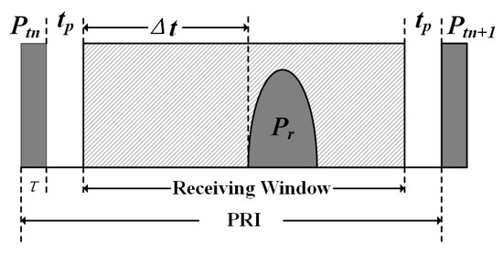
Figure 1.
The time distribution of a PRI.
A rough conceptual diagram of CVPRI is illustrated in Figure 2 for better comprehension. Suppose the first pulse is transmitted at and received at after n pulses are uniformly transmitted, the second pulse is transmitted at and received at which is located at the n + 1th PRI. The time-space in the nth receiving window can be expressed as follows:
where c is the speed of light, and the for is
If , the time shift brought by the difference of ranges can be cleared, and (4) demonstrates that the is scalable through the former interval
By exploiting this idea, the RCM over the entire integration process can be completely removed through iterative calculation. Figure 3a shows the variation of PRI during an integration time from a simulation performed with the parameters listed in Table 1 and Figure 3b gives the result of the received signal. Only a few sampling points are required in the range direction, validating the effectiveness of the method.
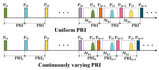
Figure 2.
The concept of CVPRI.
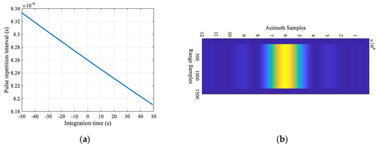
Figure 3.
(a) The variation of PRI in one synthetic aperture. (b) The received signal from the CVPRI system with the parameters listed in Table 1.

Table 1.
Simulation parameters.
2.2. High-Order Spatially Variable Two Dimensional Spectrum
The received MEO SAR signal from a point target, after demodulation to the baseband, can be expressed as follows:
where means the scattering coefficient of the point target; and denote the antenna pattern functions in the range and azimuth directions, respectively; reflects the satellite range history function; is the range phase modulation rate; is the fast time; and represents the reference slant range, which determines the location of the target, together with .
To describe the range history more accurately, the modified equivalent squinted range model (MESRM) was proposed in [29]. This accounts for equivalent acceleration in range calculation and exhibits better performance than the traditional hyperbolic range equation. However, the complex formulation of MESRM increases the computational load for subsequent operations. Therefore, for practical implementation, a Taylor series expansion is applied before performing the azimuth Fourier transform on (6). It is worth noting that the fourth-order approximation of MESRM is similar to the fourth-order Doppler range model (DRM4) [28]. The phase errors introduced by DRM4, MESRM, and the fifth-order approximation of MESRM (MESRM-T5) are shown in Figure 4, with the simulation parameters listed in Table 1. The results indicate that, within an integration time of 60 s, the phase errors of MESRM and MESRM-T5 are nearly identical. Even when the integration time extends to approximately 100 s, the phase error of MESRM-T5 is only about 0.01 radians greater than that of MESRM. Therefore, MESRM-T5 demonstrates a performance comparable to MESRM while offering higher practicality.
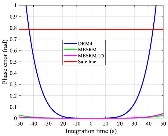
Figure 4.
The phase error introduced by each range model.
The expression of MESRM-T5 is given as follows:
where , , , and represent the first four-order Doppler coefficients.
Substitute the MESRM-T5 into (6), the SV2D spectrum can be obtained through the principle of stationary phase (POSP) and series reversion [30], as shown in (Appendix A):
2.3. Sever Space Variation of Doppler Parameters
According to (9), , which only relates to the Doppler center frequency, , is maintained at a stationary point by the beam steering control in a spaceborne SAR platform [31,32,33] and varies less than in the whole scene. Therefore, the focusing quality of each target corresponds mainly to the coefficient , and regards as a constant in the subsequent analysis. The phase error raised by other spatially variable terms both in range and azimuth directions is elaborated in Figure 5.
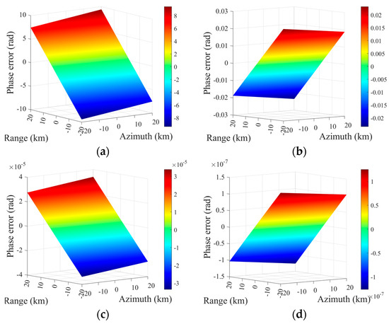
Figure 5.
The phase error raised by the space variation of polynomial coefficients across a 40 km by 40 km scene. (a) Second-order coefficient. (b) Third-order coefficient. (c) Fourth-order coefficient. (d) Fifth-order coefficient.
As presented in Figure 5, the effects of parameter spatial variation, , are much larger than others, which leads primarily to the deterioration of the edge targets and corresponds only to the Doppler frequency modulation rate . Therefore, due to their negligible introduced phase error and to reduce computation, , , are similarly regarded as the constant terms.
Performing the Taylor series expansion on the phase of the SV2D spectrum in the range direction, we find the following:
where
where
These range-independent terms represent the azimuth match filter and target RCM and range frequency modulation rate in the range Doppler (RD) domain. The most intuitive influence caused by the variation of is the mismatch of the match filter in both range and azimuth directions. The degree of mismatch raised in azimuth is already given in Figure 5a, in which it can be seen that the phase error is far greater than π/4. As for (13), due to the azimuth frequency and azimuth position , the impact of space variation on the azimuth direction is less than the range direction, which is shown in Figure 6a and Figure 6b respectively. Unlike with (11), the SAR signal is cross-coupled on range and azimuth, so another range frequency modulation rate scaling operation is required before the range compression in order to avoid range defocusing of the results. Moreover, the variation of causes not only the mismatch but also the azimuth space variation of RCM. Traditional frequency domain imaging algorithms consider the targets in the same range gates experiencing the Doppler history identically, so the RCM in the whole scene is only range correlated and can be eliminated easily through range shift and interpolation. Based on the aforementioned analysis, the azimuth invariant assumption of RCM is no longer suitable and will remain the residual RCM after bulk RCMC. Figure 6c illustrates the variation of residual RCM in the center range gate. The red dotted line points out the safe line of one eighth range gate and the others reflect the residual RCM of each target located in the different azimuth position. This situation indicates that the SAR signals of edge targets are still range–azimuth coupled, and leads to the curved distortion in the focusing results after the azimuth match filter is applied.
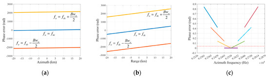
Figure 6.
The effects of the Doppler parameter spatial variation. (a) The phase error introduced in range chirp rate due to the azimuth space variation. (b) The phase error introduced in range chirp rate due to the range space variation. (c) The residual RCM of targets are evenly distributed in the center Doppler gate.
3. Focusing Method for Highly Squinted MEO SAR
A novel focusing method, as per the flowchart displayed in Figure 7, is proposed in this paper to cover the shortage of traditional imaging algorithms for highly squinted MEO SAR. Four different parts contained in this method guarantee high-quality focusing: the azimuth time scaling transform, to reduce the bulk azimuth space variation of the Doppler parameters; the range scaling, to equalize the range chirp rate in the different range gates; the NUFFT-based RCMC, to eliminate the azimuth–range couple of the SAR signal after range compression; and the NCS operation for every range gate, to remove the residual-range-dependent azimuth space variation of the Doppler parameters. The specific steps are described in detail below.
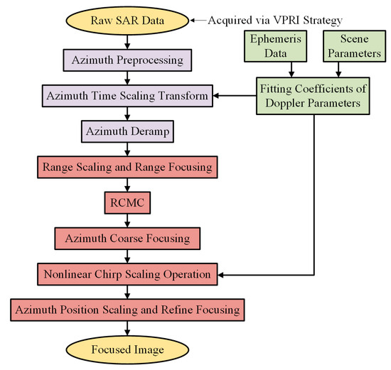
Figure 7.
The flowchart of the proposed focusing method.
3.1. Azimuth Time Scaling Transform and Preprocessing
The highly squinted MEO SAR echo acquired by the VPRI strategy reduces the data volume by removing the RCM of the scene center target in the azimuth time domain. Therefore, before subsequent processing, this missing feature must first be compensated for. Define the original azimuth time on the nonperiodic grid as , the RCM can be re-added through the complex multiplication in the range frequency domain easily as (15).
where represents the RCM of the scene center target. Here, attention should be paid to the phenomenon of range time aliasing due to the limited range sampling points, as this will hinder subsequent range focusing. Then, the modified JTDRA is adopted to alleviate the spatial variability of the Doppler parameters in the azimuth direction. Based on the analysis above, only the variation of is of concern. However, the coupling between the range frequency and range position makes the equalizing challenging for every range gate. In this step, we take the variation rate of the center range gate as the reference and apply it to the whole scene to remove the substantial part of the variation, which is shown in Figure 8. Suppose the resampled azimuth time is , the relationship between and can be modeled as (16).
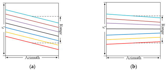
Figure 8.
The space variation of the second-order Doppler parameters. (a) Before the bulk equalization and (b) after the bulk equalization.
Substitute (16) to the MESRM-T5
where is the reference slant range of the center range gate, and the second coefficient of (17) is
where is the constant term and can be excluded from transforming through the Doppler center frequency shift. Therefore, to equalize the Doppler frequency modulation rate in the azimuth direction, (19) must be established.
where represents the location of the scene center target. By solving this differential equation, the expression of can be obtained as (Appendix B)
According to this, the NUFFT is applied to equalize . After inserting (20) back into MESRM-T5, the range model becomes
Another problem is the azimuth spectrum aliasing caused by the sliding spotlight working mode and the large squinted angle. The simulation parameters given in Table 1 indicate that, in order to reach the ideal resolution, the Doppler bandwidth needs to be larger than the PRF, which is limited by the range ambiguities of the MEO SAR system. Additionally, the 2D spectrum of the squinted SAR is tilted along with the range frequency due to the large range walk. The deramp processing [34] is an efficient method to remove the impact of aliasing. It convolutes the signal with a quadratic phase function (23)
where is the frequency modulation rate of the steering point. For the practical strategy, ref. [35] reduced the calculation by splitting the convolution operation into two, a complex multiplication and an FFT. An optimized deramp process is adopted here, which is based on the achievement of [35] but which is more suitable for the resampled signal. The non-linear phase filter contains the linear range walk correction and the first exponential function of deramp, applied before the time scaling transform, is given in (24).
Notice that the different variables of time are adopted in this function. Then, the NUFFT is performed to achieve the time scaling transform and the FFT operation of the optimized deramp. After the zeros padding in the azimuth to supplement the area for the signal shift due to the squinted angle, the signal needs to be converted back to the azimuth time domain again by IFFT to re-add the linear range walk, given in (25), to maintain the squinted feature of the signal.
Here, is uniformly distributed in [, ], while is the integration time. Converting back by the FFT, the PRF is increased as
where represents the azimuth samples, and the second exponential function of deramp is
where is distributed in [, ]
After the second exponential function is multiplied, the azimuth aliasing of the SAR data acquired in the sliding spotlight mode is successfully eliminated and the complete spectrum can be obtained by the azimuth FFT.
3.2. Range Focusing and RCMC
With the improvement in resolution, the impact brought by the high-order term in (10) gradually becomes non-negligible. A quantitative analysis of the phase error raised by each order term for LEO SAR is given in [36] and demonstrates the necessity of the range of high-order compensation in the traditional LEO situation. An analogous simulation for MEO SAR was performed and the result is elaborated in Figure 9. It can be seen that the phase error emerges as an asymmetric shape and is far beyond the tolerance of the processing. This high-order residual phase error will lead the sidelobe of the targets not only be asymmetric but elevated.
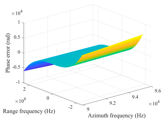
Figure 9.
The asymmetric phase error introduced by the range high-order term.
To prevent the range degradation of the targets caused by this, a high-order term filter based on the SV2D spectrum is utilized. However, due to the coupling of the frequency and position, both in range and azimuth, it is hard to compensate high-order terms accurately for every target. Here, we use the scene center target to approximate others. The high-order phase filter can be described as
The bulk RCMC is also performed in this step to reduce the range crossing of the SAR signal in the RD domain. Based on the analysis in Section 2, the range linear term (12) contains information on RCM in the RD domain. After the Doppler parameters are equalized by the azimuth time scaling transform, it is no longer related to the azimuth position and can be expressed as
where is calculated by the modified Doppler parameters in (22), and the bulk RCMC filter is given as
According to Figure 6b, the range space variation of the range chirp rate in the RD domain must also be examined. Its linear variation trend allows us to use non-linear chirp scaling to eliminate the mismatch of the range focusing filter. However, the severe range time aliasing in the RD domain mentioned above makes it difficult to apply the non-linear cubic phase function directly. Therefore, the re-expansion of the chirp signal is employed to shorten the range duration. The expression of the chirp rate in the RD domain after Doppler parameters equalizing is given by
Then, a chirp rate substitution filter, given in (33), is applied to re-expand the chirp signal.
where is the scale parameter. The range chirp rate of each target is replaced by
and
Because the range bandwidth is limited by the window function of the spectrum, the band limited filter (33) will adjust the pulse duration , as illustrated in Figure 10 and the relationship between the pulse length before and after chirp re-expansion is given in (36).
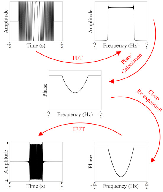
Figure 10.
A rough illustration of the chirp re-expansion.
Thus, the range time aliasing can be eliminated, and we can apply non-linear chirp scaling to equalize the range chirp rate. The variation of the chirp rate is given by
where and represent the reference slant range of the proximal and distal scene, respectively, and the cubic phase function is given as
In the end, a modified range match filter, described as (39), is applied to achieve the range’s high-quality focusing.
A pitfall here is worth noting. The nonlinear cubic function will change the phase center of the chirp signal, where the compressed pulse emerged. If the pulse length scale parameter is set too large, the re-expanded chirp signal will become very short and the phase center may be shifted out of the pulse duration, ultimately causing the energy leakage. Therefore, the re-expansion must ensure that the shifted phase center is still contained in the duration.
The final step of range processing is RCMC based on NUFFT. The accurate range-focused signal after bulk RCMC is presented in Figure 11, which illustrates that the characteristic of the RCM range space variant extends the signal across multiple range gates but cannot be handled through a simple range shift. The Stolt mapping and hybrid correlation are widely used and accurate correction methods, but they each require additional operations. The chirp scaling method only needs complex multiplication; however, it is only preferable for the linear-term-dominated RCM. The RCM space variation of the SAR signal can be considered as the non-uniform sampling at each azimuth frequency . Therefore, if we scale the range time axis along with , the range space variant RCM can be corrected completely. Traditionally, this idea is realized by the sinc interpolation, but as per the aforementioned analysis, the performance of sin interpolation is limited by computation and precision. The ability to directly map the signal from the regular grid to the irregular grid means that the NUFFT is a more practical substitute. The SAR signal after application (39) is distributed in the uniform sampled range frequency domain, and the remaining RCM, which contains two parts, is given as
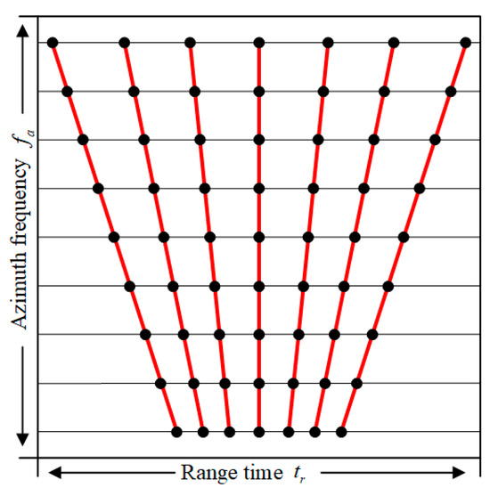
Figure 11.
The range space variant RCM performed in the range time domain.
The first part is the residual RCM remaining after bulk RCMC, and the second part is the phase center shift introduced by the cubic function in non-linear chirp scaling. Based on this, the scaled range time in each azimuth frequency can be derived as
where is the original uniform sampled range time. By adopting the inverse NUFFT to map the SAR signal from the uniform range frequency to the scaled range time , illustrated in Figure 12, the RCMC can be achieved successfully, and all range processing is finished.
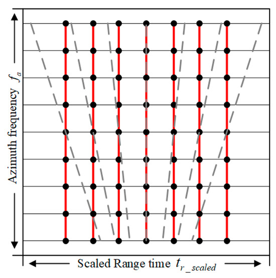
Figure 12.
The range time scale achieved by NUFFT to implement RCMC.
3.3. Azimuth Focusing and Position Scaling
The range and azimuth terms are no longer coupled when the range processing is accomplished. Thus, the range-dependent high-order match filter, which is derived in (44), can be applied for every range gate. The first exponent term in (44) is the conjugation of (11), and the second term is introduced by the deramp operation. For the targets located in the center range gate and center Doppler time, the sufficient order terms ensure adequate focusing depth and symmetrical sidelobe in the azimuth direction by performing the azimuth FFT directly. However, for the other targets, a slight mismatch in azimuth exists because of the residual Doppler parameter space variation after the azimuth time scaling transform, which will be considered in the following steps.
Owing to the deramp operation, the targets obtained by performing FFT directly from the signal, after applying (44), will embody the azimuth gathering. To adjust them to their corresponding positions, azimuth position scaling is employed to extend the image range. The first step is applying a quadratic phase function (45) in the RD domain and taking the azimuth IFFT, which can be regarded as the chirp re-expansion in the azimuth direction. After that, the previously compressed signal is expanded into chirp form, and its phase center is distributed along with the azimuth position again.
where
Considering the residual space variation of the Doppler parameters, for each range gate, an additional quadratic phase term will remain after the azimuth time scaling transform and azimuth course, focusing on the RD domain before the azimuth IFFT as
where
After applying (45), the whole scaling rate will be changed, and the trend that emerges varies along with the range position and azimuth position . The new scaling rate can be described as
Here, the range and azimuth are decoupled, so we can use a cubic phase filter (50) to equalize the for each range gate based on the NCSA after the azimuth IFFT and compensate for the extra introduced cubic term in the 2D frequency domain by applying (51).
Similar to [13], a range-dependent Doppler shift is introduced through (50), and is given by
Fortunately, the variation of is much smaller than the Doppler frequency modulation rate , so its impact is negligible.
After that, the residual range coupled space variation of the Doppler parameters is eliminated completely, and the final scaling filter (53) is applied to clear the quadratic phase term, which is artificially introduced, and the azimuth IFFT is taken to obtain the well-focused image. After employing the position scaling operation, the PRF is changed to (54).
4. Simulation
In order to verify the effectiveness of the proposed imaging method, a full scene simulation based on Table 1 is performed. An array of 25-point targets is uniformly distributed in a parallelogram area of 40 km × 40 km in ground range and azimuth, as described in Figure 13. Meanwhile, for comparison, the results obtained by the NCSA-based method proposed in [13] and the BP-based algorithm from [20] are used. No window function or any other sidelobe control method is applied here, so as to present the intrinsic focusing properties and responses of the targets more intuitively.
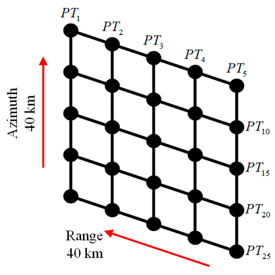
Figure 13.
The target distribution in the ground scene.
The signal-receiving strategy is improved first. According to the analysis in Section 2.1, to handle the severe range walk brought by the elevated orbit and highly squinted angle in MEO SAR, CVPRI is embedded to remove the RCM of the scene center target so as to achieve complete signal reception and data volume reduction. However, as per the equations given above, the CVPRI requires a large amount of complex floating-point arithmetic. For the embedded systems with limited computing resources in the satellite, this is a heavy burden to carry for real-time but highly precise calculation. Therefore, to achieve wider applicability for the current SAR system, an improvement is made based on [10]. The PRF does not vary continuously but with discrete steps. In this situation, the RCM of the scene center target is partially residual but still achieves the goal of complete signal reception and data volume reduction, which can be regarded as a compromise between the CVPRI and traditional SAR system.
Figure 14 gives the result of the scene center target’s signal received through the discretely variable PRF strategy with the step of 0.1 Hz. Compared with the result given in Figure 3b, the edge of the echo is not smooth but emerges as a serrated edge, which donates the residual RCM of the target, and the PRF would vary about every 500 pulses with this configuration. The slightly increased range samples indicate the performance gap between the discretely variable PRF and CVPRI, but, on the whole, the impact brought by the severe range walk is effectively alleviated, and the subsequent operations are not complicated by this technology.
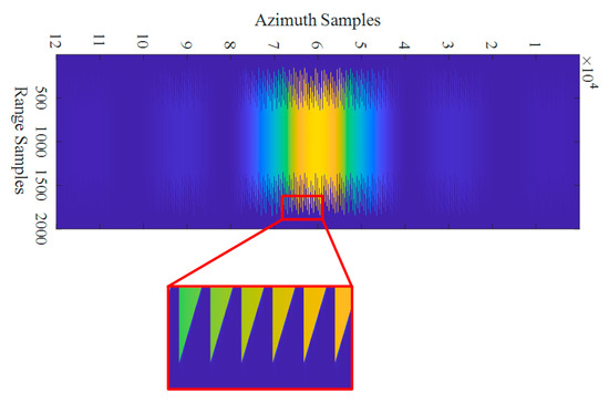
Figure 14.
The echo of the scene center target received through the discretely variable PRF strategy with the step of 0.1 Hz.
The contour plots of , , , and , focused by the proposed method, are given in Figure 15, and their corresponding azimuth profiles are given in Figure 16. For comparison, the results from the NCSA-based method are shown in Figure 17 and Figure 18, and those from the BP-based algorithm are shown in Figure 19 and Figure 20.
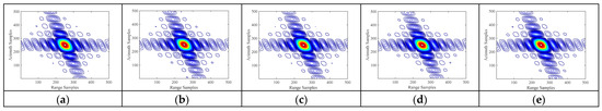
Figure 15.
The 2D contour plots of the chosen targets after applying the proposed method. (a–e) Results of targets , , , and , respectively.
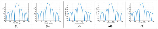
Figure 16.
The azimuth profiles of the chosen targets after applying the proposed method. (a–e) Results of targets , , , and , respectively.
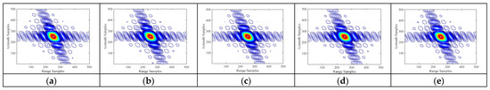
Figure 17.
The 2D contour plots of the chosen targets after applying the NCSA-based method. (a–e) Results of targets , , , and , respectively.
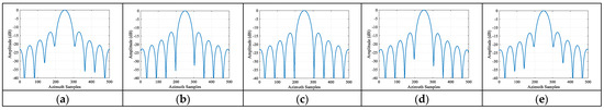
Figure 18.
The azimuth profiles of the chosen targets after applying the NCSA-based method. (a–e) Results of targets , , , and , respectively.
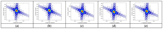
Figure 19.
The 2D contour plots of the chosen targets after applying the BP-based algorithm. (a–e) Results of targets , , , and , respectively.
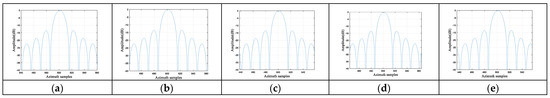
Figure 20.
The azimuth profiles of the chosen targets after applying the BP-based algorithm. (a–e) Results of targets , , , and , respectively.
First, comparing the proposed method with the NCSA-based method, it can be observed that is well-focused by both methods, which proves the high precision of the established SV2D spectrum and its ability to fit the high-order terms in the signal acquired by the long time integration of the MEO SAR. However, for the other targets, a performance gap between the two methods becomes apparent. The NCSA-based method uses an additional cubic perturbation phase function to remove most of the quadratic phase error caused by the spatial variation of Doppler parameters. However, this extra introduced cubic term causes the azimuth sidelobe to be asymmetric for every target. The NCSA-based method compensates for this degradation by applying a cubic phase function in the azimuth frequency domain, but this compensation is based on the assumption of an invariable stationary phase point due to the initially small variation of the Doppler parameters. As the spatial variation increases towards the scene edges, this premise becomes untenable and ultimately leads to further focus degradation. Additionally, the NCSA-based method considers only the variation rate at the center range gate. Therefore, for the edge targets, the residual space-variant quadratic phase error is not completely compensated, preventing the achievement of the expected azimuth resolution due to non-negligible main-lobe broadening. This phenomenon is particularly reflected in Figure 18. While the azimuth profile of the center target in Figure 18c aligns well with the theoretical profile, a slight elevation of the first zero-crossing points is visible for and in Figure 18b,d, respectively, which are located 10 km away from the scene center in both range and azimuth directions. This indicates the existence of residual phase error and presents a bottleneck for the NCSA-based method. For the edge targets, and , severe azimuth broadening is shown in Figure 18a,e. The depth of the first sidelobe nears −20 dB, and most of its energy is incorporated into the main lobe, manifesting as azimuth blurring in the 2D contour plots in Figure 17a,e.
In contrast to the BP-based algorithm, which achieves excellent yet computationally expensive [37] focusing (as shown in Figure 19 and Figure 20), the proposed method offers a far more efficient alternative while also addressing the core limitations of the BP-based algorithm. Specifically, the proposed method overcomes the defect related to the shift of the stationary phase point by incorporating the Doppler parameter variation—introduced by the azimuth time scaling transform—directly into the SV2D spectrum calculation. This ensures more accurate focusing for the scene-center target. For targets at the range edge, the residual phase error is effectively cleared by the subsequent NCSA step, yielding superior focusing performance compared with the NCSA-based method. The results validate the effectiveness of our approach: all targets are well focused, with the depth of the first zero-crossing point approaching or even exceeding −40 dB (Figure 16), and the 2D contour plots show no geometric distortion (Figure 15).
The evaluation values of , , , and focused by the proposed method are given in Table 2 from a quantitative point to view, while and represent the azimuth and range resolution, respectively. The theoretical peak sidelobe ratio (PSLR) and integral sidelobe ratio (ISLR) are −13.26 dB and −9.68 dB, respectively, when the rectangular window function is applied both in the range and azimuth directions. According to Table 2, the range evaluations of each target are almost approaching the ideal results. The range broadening is less than 1.0%, and the deviation of PSLR and ISLR is less than 0.3 dB and 0.4 dB, respectively. As for the azimuth dimension, the high-quality focusing achieved by the proposed method maintains the evaluation results of the edge targets as the same as the center reference target. The maximum azimuth IRW is 1.874%, and the PSLR deviation is less than 0.4 dB. Due to the zero padding in the azimuth frequency domain, the sidelobe number is less than the range dimension obtained via the ISLR calculation, so it is reduced slightly but does not affect the evaluation results of the targets.
Table 2.
Imaging performance of the chosen targets.
To verify the effectiveness and robustness of the proposed method, we conducted simulation experiments based on a distributed scene. The simulation parameters are listed in Table 1, and the imaging results are shown in Figure 21. The results indicate that the proposed method maintains good focusing performance even when processing more realistic continuous scattering scenarios.
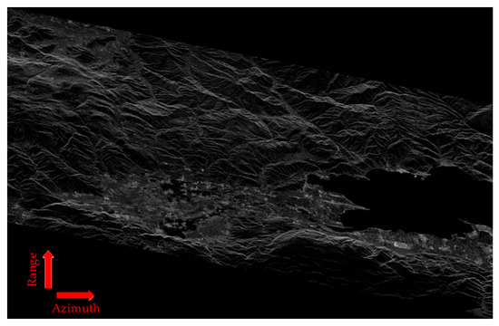
Figure 21.
The distributed scene imaging results obtained by applying the proposed method.
5. The Discussion of the Computation Burden
The computation burden is an important aspect to evaluate the effectiveness of the imaging method. Table 3 gives the comparison results of the proposed and the NCSA-based method. NUFFT is embedded in the proposed method and its calculation complexity must be addressed. According to [22], suppose the oversampling ratio is c and the length of interpolation kernel is K, then, the calculation complexity of a one-dimensional NUFFT performed on a series with length M is given as
Based on this, the total calculation complexity of the proposed method can be obtained by
where represents the azimuth samples of the final image and represents the range samples. To balance the satisfactory accuracy and computation burden, the oversampling ratio c is set as 2 and the interpolation kernel K is set as 6. Then, (56) can be summarized as
Table 3.
The analysis of calculation complexity.
The comparison of the computation burden for the proposed method and the NCSA-based method is given in Figure 22 by assuming . It can be seen that the calculation complexity of the proposed method increased faster than the NCSA-based method along with an increasing in the number of sampling numbers, primarily due to the introduction of NUFFT. As the number of samples is greater than 214, the number of required computation operations of the proposed method is almost twice the reference. However, the application of VPRI can enable the proposed method to image scenes of the same size on half or even fewer sampling points than others. Therefore, a satisfactory calculation efficiency can still be obtained in practical application.
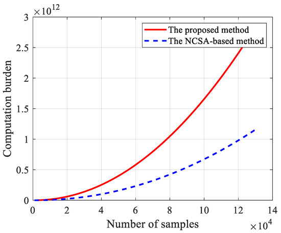
Figure 22.
Comparison of the computation burden for the proposed method and the NCSA-based method.
6. Conclusions
This paper presents a series of analyses for highly squinted MEO SAR data processing. First, the VPRI technique is introduced to address the severe range walk. Then, considering the spatial variation of Doppler parameters caused by the complex imaging geometry and highly squinted operating mode, a high-order spatially variable 2D spectrum is established in Section 2.2 to quantify the impact of this variation. Based on this, the introduced phase errors, both by the mismatch of the match filter and the residual RCM, are given in Section 2.3, which validates the necessity of the followed Doppler equalizing operation.
A novel method for full-scene data processing is subsequently proposed in Section 3. Compared with the conventional wide-swathe algorithms, the spatial variation of the Doppler parameters is alleviated by jointly applying the principle of JDTRA and NCSA. The MEO SAR raw data are firstly acquired through the VPRI strategy, then the modified azimuth time scaling transform is employed to achieve the spectrum reconstruction from the nonperiodic sampled data and most of the Doppler parameter space variation is removed. After range focusing and RCMC, the signal is no longer range–azimuth coupled, and azimuth focusing is subsequently employed. The NCSA is utilized after the coarse azimuth focusing to eliminate the residual space variant quadratic phase error. By accounting for the range variation of the Doppler parameter rates, the proposed method can handle edge target focusing more effectively. In order to process the data more precisely, NUFFT is adopted in this paper to substitute the interpolation operation in both azimuth time scaling transform and RCMC. The scaling results achieved by the NUFFT algorithm are no longer limited by the interpolation kernel length as in traditional operations, but depend on the oversampling ratio and the choice of the compactly supported window function. The simulated results in Section 4 verify the high accuracy of the SV2D spectrum and the effectiveness of the proposed imaging algorithm, while Section 5 discusses the computational burden.
Author Contributions
Conceptualization, H.Y. and T.H.; methodology, H.Y.; validation, P.W. and J.C.; formal analysis, Z.M.; investigation, H.Y.; resources, H.Y.; writing—original draft preparation, H.Y. and T.H.; writing—review and editing, P.W.; visualization, H.Y.; supervision, J.C.; project administration, P.W.; funding acquisition, P.W. All authors have read and agreed to the published version of the manuscript.
Funding
This research was supported by the National Natural Science Foundation of China under grants U2241202 and U23B2007.
Data Availability Statement
The raw data supporting the conclusions of this article will be made available by the authors on request.
Conflicts of Interest
The authors declare no conflicts of interest.
Abbreviations
The following abbreviations are used in this manuscript:
| MEO | Medium-earth orbit |
| SAR | Synthetic aperture radar |
| SV2D | Spatially variable two-dimensional |
| VPRI | Variable pulse repetition interval |
| NUFFT | Non-uniform fast Fourier transform |
| RCM | Range cell migration |
| NCSA | Non-linear chirp scaling algorithm |
| LEO | Low-earth orbit |
| SNR | Signal-to-noise ratio |
| LTI | Linear time invariant |
| PRI | Pulse repetition interval |
| JTDRA | Joint time and Doppler resampling algorithm |
| BP | Back-Projection |
| RCMC | Range cell migration correction |
| CVPRI | Continuously varying pulse repetition interval |
| MESRM | Modified equivalent squinted range model |
| DRM4 | Fourth-order Doppler range model |
| MESRM-T5 | Five-order approximation of MESRM |
| POSP | Principle of stationary phase |
| RD | Range Doppler |
| FFT | Fast Fourier transform |
| IFFT | Inverse fast Fourier transform |
| PSLR | Peak sidelobe ratio |
| ISLR | Integral sidelobe ratio |
Appendix A
Substitute the MESRM-T5 into (6) and employ the range Fourier transform through POSP, the received SAR signal in the azimuth time and range frequency domain is given by
where is the carrier frequency. In order to achieve the series reversion, only the items of second order and above in the last exponential term are considered here as
Then, the POSP is applied to achieve the azimuth Fourier transform . The azimuth slow time can be described by the azimuth frequency through the series reversion as
Based on this, the SV2D spectrum of (6) can be obtained as
Appendix B
Suppose varies as a quadratic curve
a and b represent each order polynomial coefficient, and (19) can be expanded as (A8).
where
so the expression of can be obtained through the integrate as
References
- Chen, C.; Moussessian, A. MEO SAR system concepts and technologies for earth remote sensing. In Proceedings of the AIAA Space Conference, San Diego, CA, USA, 28–30 September 2004; pp. 1483–1485. [Google Scholar]
- Klein, U.; Lin, C.C.; Atkinson, N.; Charlton, J.; Philpot, C. Future microwave radiometers in geostationary and medium earth orbit. In Proceedings of the IGARSS 2003. 2003 IEEE International Geoscience and Remote Sensing Symposium. Proceedings (IEEE Cat. No.03CH37477), Toulouse, France, 21–25 July 2003; pp. 2158–2160. [Google Scholar] [CrossRef]
- Matar, J.; Lopez-Dekker, P.; Krieger, G. Potentials and Limitations of MEO SAR. In Proceedings of the EUSAR 2016: 11th European Conference on Synthetic Aperture Radar, Hamburg, Germany, 6–9 June 2016; pp. 1–5. [Google Scholar]
- Matar, J.; Rodriguez-Cassola, M.; Krieger, G.; López-Dekker, P.; Moreira, A. MEO SAR: System Concepts and Analysis. IEEE Trans. Geosci. Remote Sens. 2020, 58, 1313–1324. [Google Scholar] [CrossRef]
- Monti Guarnieri, A.; Broquetas, A.; Recchia, A.; Rocca, F.; Ruiz-Rodon, J. Advanced Radar Geosynchronous Observation System: ARGOS. IEEE Geosci. Remote Sens. Lett. 2015, 12, 1406–1410. [Google Scholar] [CrossRef]
- Wang, F.; Zhang, B.; Yang, D.; Li, W.; Zhu, Y. Sea-State Observation Using Reflected BeiDou GEO Signals in Frequency Domain. IEEE Geosci. Remote Sens. Lett. 2016, 13, 1656–1660. [Google Scholar] [CrossRef]
- Tomiyasu, K.; Pacelli, J.L. Synthetic Aperture Radar Imaging from an Inclined Geosynchronous Orbit. IEEE Trans. Geosci. Remote Sens. 1983, GE-21, 324–329. [Google Scholar] [CrossRef]
- Xu, H.; Huang, L.; Qiu, X.; Han, B.; Zhong, L.; Meng, D. A New Geosynchronous SAR Constellation and its Signal Characteristics. IEEE Access 2019, 7, 101539–101551. [Google Scholar] [CrossRef]
- Ding, Z.; Yin, W.; Zeng, T.; Long, T. Radar Parameter Design for Geosynchronous SAR in Squint Mode and Elliptical Orbit. IEEE J. Sel. Top. Appl. Earth Obs. Remote Sens. 2016, 9, 2720–2732. [Google Scholar] [CrossRef]
- Men, Z.; Wang, P.; Li, C.; Chen, J.; Liu, W.; Fang, Y. High-Temporal-Resolution High-Spatial-Resolution Spaceborne SAR Based on Continuously Varying PRF. Sensors 2017, 17, 1700. [Google Scholar] [CrossRef]
- Zeng, T.; Li, Y.; Ding, Z.; Long, T.; Yao, D.; Sun, Y. Subaperture Approach Based on Azimuth-Dependent Range Cell Migration Correction and Azimuth Focusing Parameter Equalization for Maneuvering High-Squint-Mode SAR. IEEE Trans. Geosci. Remote Sens. 2015, 53, 6718–6734. [Google Scholar] [CrossRef]
- Wong, F.H.; Cumming, I.G.; Neo, Y.L. Focusing Bistatic SAR Data Using the Nonlinear Chirp Scaling Algorithm. IEEE Trans. Geosci. Remote Sens. 2008, 46, 2493–2505. [Google Scholar] [CrossRef]
- Guo, Y.; Wang, P.; Chen, J.; Men, Z.; Cui, L.; Zhuang, L. A Novel Imaging Algorithm for High-Resolution Wide-Swath Space-Borne SAR Based on a Spatial-Variant Equivalent Squint Range Model. Remote Sens. 2022, 14, 368. [Google Scholar] [CrossRef]
- Chen, J.; Kuang, H.; Yang, W.; Liu, W.; Wang, P. A Novel Imaging Algorithm for Focusing High-Resolution Spaceborne SAR Data in Squinted Sliding-Spotlight Mode. IEEE Geosci. Remote Sens. Lett. 2016, 13, 1577–1581. [Google Scholar] [CrossRef]
- Men, Z.; Wang, P.; Chen, J.; Li, C.; Liu, W.; Yang, W. Advanced high-order nonlinear chirp scaling algorithm for high-resolution wide-swath spaceborne SAR. Chin. J. Aeronaut. 2021, 34, 563–575. [Google Scholar] [CrossRef]
- Liu, W.; Sun, G.-C.; Xia, X.-G.; Chen, J.; Guo, L.; Xing, M. A Modified CSA Based on Joint Time-Doppler Resampling for MEO SAR Stripmap Mode. IEEE Trans. Geosci. Remote Sens. 2018, 56, 3573–3586. [Google Scholar] [CrossRef]
- Li, D.; Wu, M.; Sun, Z.; He, F.; Dong, Z. Modeling and Processing of Two-Dimensional Spatial-Variant Geosynchronous SAR Data. IEEE J. Sel. Top. Appl. Earth Obs. Remote Sens. 2015, 8, 3999–4009. [Google Scholar] [CrossRef]
- Tang, S.; Lin, C.; Zhou, Y.; So, H.C.; Zhang, L.; Liu, Z. Processing of Long Integration Time Spaceborne SAR Data With Curved Orbit. IEEE Trans. Geosci. Remote Sens. 2018, 56, 888–904. [Google Scholar] [CrossRef]
- Liu, W.; Sun, G.-C.; Xia, X.-G.; You, D.; Xing, M.; Bao, Z. Highly Squinted MEO SAR Focusing Based on Extended Omega-K Algorithm and Modified Joint Time and Doppler Resampling. IEEE Trans. Geosci. Remote Sens. 2019, 57, 9188–9200. [Google Scholar] [CrossRef]
- Li, H.; Liu, W.; Sun, G.; Xing, M.; Li, G.; Fei, X. MEO SAR imaging based on imaging coordinate system optimization. J. Radars 2020, 9, 856–864. [Google Scholar] [CrossRef]
- Nguyen, N.; Liu, Q. The regular Fourier matrices and nonuniform fast Fourier transforms. SIAM J. Sci. Comput. 1999, 21, 283–293. [Google Scholar] [CrossRef]
- Dutt, A.; Rokhlin, V. Fast Fourier transforms for nonequispaced data. SIAM J. Sci. Comput. 1993, 14, 1368–1393. [Google Scholar] [CrossRef]
- Keiner, J.; Kunis, S.; Potts, D. Using NFFT 3-a software library for various non-equispaced fast Fourier transforms. ACM Trans. Math. Softw. 2009, 36, 19–30. [Google Scholar] [CrossRef]
- Xu, H.; Gao, J.; Li, J. A variable PRF imaging method for high squint diving SAR. Prog. Electromagn. Res. 2013, 135, 215–229. [Google Scholar] [CrossRef]
- Chen, S.; Huang, L.; Qiu, X.; Shang, M.; Han, B. An improved imaging algorithm for high-resolution spotlight SAR with continuous PRI variation based on modified sinc interpolation. Sensors 2019, 19, 389. [Google Scholar] [CrossRef]
- Zhou, Z.-X.; Deng, Y.; Wang, W.; Jia, X.; Wang, R. Analysis of Varying-PRI Spotlight SAR Data. IEEE Trans. Geosci. Remote Sens. 2022, 60, 5221020. [Google Scholar] [CrossRef]
- Zhao, S.; Deng, Y.; Wang, R. Imaging for High-Resolution Wide-Swath Spaceborne SAR Using Cubic Filtering and NUFFT Based on Circular Orbit Approximation. IEEE Trans. Geosci. Remote Sens. 2017, 55, 787–800. [Google Scholar] [CrossRef]
- Eldhuset, K. A new fourth-order processing algorithm for spaceborne SAR. IEEE Trans. Aerosp. Electron. Syst. 1998, 34, 824–835. [Google Scholar] [CrossRef]
- Wang, P.; Liu, W.; Chen, J.; Niu, M.; Yang, W. A High-Order Imaging Algorithm for High-Resolution Spaceborne SAR Based on a Modified Equivalent Squint Range Model. IEEE Trans. Geosci. Remote Sens. 2015, 53, 1225–1235. [Google Scholar] [CrossRef]
- He, T.; Cui, L.; Wang, P.; Guo, Y.; Zhuang, L. A Novel Ultra-High Resolution Imaging Algorithm Based on the Accurate High-Order 2-D Spectrum for Space-Borne SAR. Remote Sens. 2022, 14, 2284. [Google Scholar] [CrossRef]
- Fiedler, H.; Boerner, E.; Mittermayer, J.; Krieger, G. Total zero Doppler steering—A new method for minimizing the Doppler centroid. IEEE Geosci. Remote Sens. Lett. 2005, 2, 141–145. [Google Scholar] [CrossRef]
- Scharf, D.P. Analytic yaw–pitch steering for side-looking SAR with numerical roll algorithm for incidence angle. IEEE Trans. Geosci. Remote Sens. 2012, 50, 3587–3594. [Google Scholar] [CrossRef]
- Davidson, G.W.; Cumming, I. Signal properties of spaceborne squint-mode SAR. IEEE Trans. Geosci. Remote Sens. 1997, 35, 611–617. [Google Scholar] [CrossRef]
- Lanari, R.; Tesauro, M.; Sansosti, E.; Fornaro, G. Spotlight SAR data focusing based on a two-step processing approach. IEEE Trans. Geosci. Remote Sens. 2001, 39, 1993–2004. [Google Scholar] [CrossRef]
- Wang, P.; Zhou, Y.; Chen, J.; Li, C.; Yu, Z.; Min, H. A Deramp Frequency Scaling Algorithm for Processing Space-Borne Spotlight SAR Data. In Proceedings of the 2006 IEEE International Symposium on Geoscience and Remote Sensing, Denver, CO, USA, 31 July–4 August 2006; pp. 3148–3151. [Google Scholar] [CrossRef]
- Chen, X.; Yi, T.; He, F.; He, Z.; Dong, Z. An Improved Generalized Chirp Scaling Algorithm Based on Lagrange Inversion Theorem for High-Resolution Low Frequency Synthetic Aperture Radar Imaging. Remote Sens. 2019, 11, 1874. [Google Scholar] [CrossRef]
- He, T.; Wang, P.; Men, Z.; Yu, L.; Liu, W.; Chen, J. A Novel Nonplanar Grid Based Fast Back Projection Algorithm for ConGaL-Borne Terrain Matching SAR. IEEE J. Sel. Top. Appl. Earth Obs. Remote Sens. 2025, 18, 28873–28891. [Google Scholar] [CrossRef]


Disclaimer/Publisher’s Note: The statements, opinions and data contained in all publications are solely those of the individual author(s) and contributor(s) and not of MDPI and/or the editor(s). MDPI and/or the editor(s) disclaim responsibility for any injury to people or property resulting from any ideas, methods, instructions or products referred to in the content. |
© 2025 by the authors. Licensee MDPI, Basel, Switzerland. This article is an open access article distributed under the terms and conditions of the Creative Commons Attribution (CC BY) license.