Abstract
Tidal flats are some of the most dynamic coastal environments in the world, where traditional coastal mapping and monitoring provide insufficient temporal resolution to reliably map channels and sand flats. Satellite-based Synthetic Aperture Radar (SAR) enables regular cloud-penetrating detection of water flowing through channels within the tidal flats, referred to as tidal channels. This paper presents a method for detecting a path through tidal channels, using satellite imagery, that supports our understanding and safe exploitation of this valuable coastal environment. This approach is the first proposed to identify navigable paths in all conditions, with SAR images susceptible to variation due to weather and tidal conditions. Tidal channels are known to vary in SAR presentation, and we find that tidal flat presentation is also influenced by conditions. The most influential factor is the wind, with high winds causing an inversion in how both tidal flats and tidal channels present in SAR images. The presented method for the automatic detection of tidal channels accounts for this variability by using previous channel paths as a reference to reliably correct imagery and detect the latest path. The final algorithm produces paths with minor errors in 17.6% of images; the error rate increases to 71.7%, with an almost tenfold increase in errors, when the SAR image and paths are not adjusted to account for conditions. This capability has been used to support the Nith Inshore Rescue in attending call-outs from their base in Glencaple, UK, while the insights from monitoring tidal channels for a year demonstrate how periods of high river flow preceded major changes in the channel path.
1. Introduction
Tidal estuaries/zones, like the Solway Firth on the West Coast of Great Britain, are some of the most dynamic coastal environments in the world. The rapidly changing conditions, driven by tides and currents, create an unpredictable environment that present a range of hazards such as strong currents, rapidly changing water levels, and quicksand. Consequently, they remain uncharted or inaccurate in traditional marine charts (Figure 1). In lieu of charts, rescue services operating in these regions rely on specialised vehicles, local knowledge, and regular depth readings to navigate safely amidst the dynamic shifting sands. This experience is enhanced by coordination and communication with neighbouring rescue services and coast guards. This paper aims to chart the uncharted by providing a technique to map the latest location of navigable channels of water—referred to as tidal channels—supporting rescue services and enhancing our understanding of these unique environments.
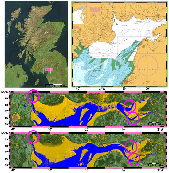
Figure 1.
(Top Left) Location of the Solway Firth marked on satellite imagery of Great Britain [1]. (Top Right) Solway Firth navigational chart showing uncharted region with River Nith labelled [2] © British Crown and OceanWise, 2020. All rights reserved. Licence No. EK001-20180802. Not to be used for navigation. (Middle and Bottom) Images of Solway Firth taken by Sentinel-2 satellite on 5 March 2020 (Middle) and 17 April 2020 (Bottom) coloured according to Normalised Difference Water Index (NDWI) to show the shifting of channels due to the strong tides and currents in the region (circled in pink). Copernicus Sentinel data 2020.
Remote sensing, specifically satellite Earth observation (EO), provides the ability to access recent imagery of tidal zones. When these images are acquired in close proximity to low tide, it is possible to identify the deepest channels that cut through the sand, rock, and mud that form tidal flats [3]. Visual imagery can clearly identify these tidal channels through the use of the Normalised Difference Water Index (NDWI) [4,5]. However, optical imagery can be obscured by clouds where, for an area like Great Britain, this can result in a significant proportion of images being unusable [6]. This becomes a prohibitive restriction for a task that is already constrained by the need to use low-tide optical imagery. Satellite-based Synthetic Aperture Radar (SAR) imagery is not obscured by cloud or fog and can be effective in detecting tidal channels by using the surface differences detected in the radar signal [5,7]. There is still often a need to use low-tide imagery to clearly distinguish tidal channels, although evidence does exist for the ability of SAR to identify tidal channels during both ebb and flood [7]. SAR has been shown to distinguish sediment type and vegetation in tidal environments [8,9], as well as support optical imagery, in monitoring tidal flats by correcting occluded regions [10], and in combination with optical imagery and deep learning, to classify of intertidal zones—in terms of tidal flat and ocean water [11]. Satellite-acquired SAR imagery has been highlighted as one of the most effective and suitable technologies for monitoring tidal zones [12]. We aim to demonstrate the ability of SAR to independently detect tidal waters flowing through tidal flats by understanding the different SAR representations of water and sediment in intertidal zones.
Satellite-based SAR penetrates through clouds but is still susceptible to the influence of the weather. The data generated from SAR signals contain both the backscatter coefficient— a measure of the amount of radar energy reflected back to the sensor—and polarimetric data—a measure detailing the polarisation of the returning radar waves. Ideal conditions, for the SAR monitoring of tidal flats, are characterised by a smooth water surface resulting in a lower backscatter coefficient compared to the surrounding land surfaces. As a result, ideal conditions are likely associated with calm weather conditions, because high winds disturb the water surface and can significantly alter the backscatter signal to such an extent that water is no longer readily distinguishable from land [13]. The influence of wind and tide is implicitly acknowledged in [11] where they are provided as inputs to the deep learning model, while in [14], the direction of wind has been explicitly used to identify submerged tidal features. Other studies choose to discard SAR images that are acquired in high wind conditions to avoid consideration of these disturbances [15]. However, discarding imagery is impractical for the purposes of detecting safe-to-navigate channels as the data available are already limited by the requirement that they must be collected in close proximity to low tide. Furthermore, timeliness of data is important. In our work, we must understand and account for the impacts of weather conditions in the acquired SAR imagery to enable the detection of safe-to-navigate channels in all weather conditions.
Identifying paths that safely navigate tidal channels from SAR imagery is part of this paper’s contribution. Ship routing algorithms often consider safe navigation, including obstacle and ship avoidance, where bounding box cells that define an area around a ship or obstacle are frequently employed [16,17]. Cells in our work are defined by the pixel resolution of the satellite imagery, where a breadth-first search (BFS) is applied to solve the maze-like problem of finding a route through the tidal flats. BFS treats the maze of adjacent cells as a graph, where this approach is among the most robust and effective graph-based maze solving methods for larger mazes [18]. The task of solving the tidal channel maze in ideal conditions with BFS is relatively trivial, with the focus of research on path identification with known obstacles focused on optimised and efficient variants of BFS [19]. The contribution of this work lies in the identification of tidal channel water and hence the avoidance of obstacles (i.e., tidal flats) that restrict the routes open to BFS exploration. The task is made more difficult due to the variation in SAR imagery seen during this study. The study of SAR variation contributes to an improved understanding of how SAR imagery can vary over tidal zones depending on weather and tidal conditions, resulting in new insights into tidal flat variation.
2. Methods—SAR Data
In this work, we focus on the use of the backscatter coefficient from the SAR signal to distinguish water channels from surrounding mud and sand. Specifically, the VV polarisation (vertical transmit and vertical receive) data from Sentinel-1 is sensitive to surface roughness, and hence can be used to readily distinguish water from mud and sand in ideal conditions to provide detailed maps of the tidal zone around low tide. The SAR images used in this work are provided by Copernicus within the Google Earth Engine (GEE) data catalogue [20]. This dataset underwent various preprocessing steps, such as orbital metadata updates, ground-range-detected boundary noise and thermal noise detection, radiometric calibration, and terrain correction to generate geocoded backscattering intensity images. These images are then converted to decibels (dB) and uploaded to the Google cloud, where they can be accessed in near-real-time by users. Using GEE’s platform, we applied a clipping to the images to only select relevant pixels within our region of interest, which encompasses parts of the river Nith and its outflow into the Solway Firth. The GEE script is available at [21]. Finally, a median filter is applied to the image to mitigate against the impact of speckle.
The SAR incidence angle is reported by GEE and varies over the region of interest; the incidence angle recorded for analysis is taken as the mean of all angles covering the region of interest.
2.1. VH Polarisation Mask
VH polarisation (vertical transmit and horizontal receive) data are also available from Sentinel-1. VH data are sensitive to the dielectric constant (relative permittivity)—a measure of the ground’s ability to store electrical energy in an electric field. The VH signal can be used to distinguish permanent coastal land from the tidal zone such that the land can be masked from the VV backscatter image. A land mask is a necessary step when detecting channel paths in certain weather conditions, as described in Section 3.2, where the tidal channel and permanent land can present similar VV polarisation intensities. VH data provide a simple and reliable mask for removing prominent dry areas of land. Standard land masks are available but, due to the resolution and accuracy of these, they can overlap with the tidal zone. For instance, applying the land/water mask algorithm [22] from the SNAP toolbox [23] produces overlap with the tidal zone and masking of the tidal channel at points of close approach to the land/tidal zone boundary. It is possible for the VH polarisation intensity mask to cover small areas of the tidal zone. These areas of high VH intensity appear to correspond with areas of high VV intensity, likely attributed to areas of sand/mud with increased surface roughness due to strong hydro-dynamic forces in that area [24]. These masked areas therefore do not represent tidal channels and instead contribute to the channel path’s avoidance of tidal flats.
2.2. Satellite Data Availability
The Sentinel-1 mission consisted of two identical satellites in near-polar sun-synchronous orbits with a 180 deg orbital phase difference. They were equipped with C-band SAR capable of collecting data at a variety of resolutions. For our purposes, the Interferometric Wide swath (IW) mode, which has a resolution of 5 m (range) × 20 m (azimuth), is used [25]. The two-satellite constellation offered a 6-day exact repeat cycle at the equator. Since the orbit track spacing varies with latitude, the revisit rate is greater at higher latitudes than at the equator. On 23 December 2021, one of the spacecraft, Sentinel-1B, suffered an anomaly and has not returned data since this date [26]. Sentinel-1C, which should replace this lost service, is due to be launched soon [27].
The area selected for investigation in this paper is a portion of the Solway Firth on the West Coast of Great Britain. The region selected extends from 55.01°N, 3.60°W (top left) to 54.92°N, 3.49°W (bottom right) as shown in Figure 2.
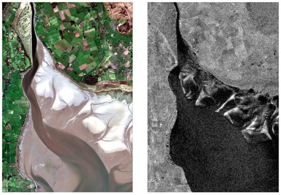
Figure 2.
Images of the area of interest where the River Nith flows into the Solway Firth on 5 March 2020, (Left) true-colour image taken by Sentinel-2 satellite and (Right) SAR image taken by Sentinel-1.
To assess the availability of suitable satellite imagery for coastal monitoring, the data available from Sentinel-1 are investigated for a 12-month period from 01/01/2021 to 31/12/2021. It is necessary to select images at sufficiently low tide height to accurately identify the location of tidal channels. When the tide height increases, areas of sand and mud become submerged to the point that an SAR image cannot clearly discern the tidal channels. For the year 2021, 111 images were collected that were visually determined to provide sufficient clarity on the location of tidal channels. Sufficient clarity is a subjective measure based on the ability to identify a clear, narrow, channel throughout the image. This assessment will be affected by weather conditions at the time of the image, but the following analysis reveals that it is predominantly a consequence of tidal conditions.
The 111 images of sufficient clarity were compared with tide heights recorded at the time of image collection. The tide height recorded around 30 km south of the tidal channel at Workington Station (54.65°N, 3.57°W) was obtained from the British Oceanographic Data Centre (BODC) [28]. For 2021, the mean tide height was 4.5 m where the highest tide height recording for the 111 images, deemed to be suitable for channel identification, was 4.46 m. A similar review of tidal heights in the same area of the Solway Firth for February–August 2022 identified 4.2 m as the maximum tide height for usable imagery [12]. While this does indicate that all usable images were acquired below mean tide, it is a misleading measure given the displacement from Workington station and the geography of the Solway Firth, both of which delay the arrival of tides. For tides that were ebbing at the time of image collection, the maximum tide height was recorded at 2.95 m, which is likely to be a more representative maximum for tide height for the area shown in Figure 2.
The Sentinel-1 satellites each provide four observation opportunities of the area of interest every 12 days. Each pass occurs at approximately 6:30UTC or 18:00UTC and the 12-day pattern repeats predictably such that, until the failure of Sentinel-1B, the two spacecraft combined provided a 6-day repeat cycle. Manually filtering the images according to sufficient-clarity criteria results in 111 images with a median coverage separation of 1 day and a maximum separation of 15 days; 10% of sufficient clarity images were separated by 10 days or greater while 67% of sufficient-clarity images fell within 2 days of the previous sufficient-clarity pass.
2.3. SAR Tidal Channel Dataset
The tidal channel detection algorithm only requires a subset of the available 111 sufficient-clarity images to generate channel paths throughout 2021. This subset of images were not selected primarily on quality but prioritised on providing a weekly coverage, where possible, of the tidal channel. While some images recorded on consecutive days remain, the majority were removed to produce a subset of 60 images that maintain a median time between images of 3 days and a maximum of 20 days; 17% of the 60 images were separated by 10 days or greater while only 25% fell within 2 days of the previous chosen image. These results suggest a clustering of images, with a similar observation for this area observed during February–August 2022 with, on average, two usable images per cluster separated by a gap of approximately 10 days, resulting in 5–8 low-tide images per month [12].
3. Methods—Detecting Tidal Channel Paths
Tidal channels form within a tidal flat as a product of the rise and fall in the tide, as well as the influence of continuous flow from rivers entering a tidal flat. The main tidal channels connecting river outlets to the sea provide important routes between well-established rivers and the consistent deep waters of the sea. In relation to the region of interest in this work, detecting the tidal channel is vital for the Nith Inshore Rescue as it connects their lifeboat station on the River Nith to the Solway Firth. Every deployment from their base in Glencaple requires the navigation of this channel to safely attend incidents in the Solway Firth and beyond.
The navigable tidal channel is visible on SAR imagery for suitably low-tide images (see Section 2.2). Both of the examples in Figure 3 provide sufficient clarity for the tidal channels, but the presentation of the tidal channel varies notably. Figure 3a presents a typical representation of tidal channels near low tide during ideal conditions. Figure 3b captures how the SAR presentation varies in other conditions, such as high winds that are known to increase water surface roughness.
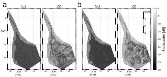
Figure 3.
VH and VV SAR images of tidal flats, with the latter with a VH polarisation intensity mask applied for (a) ideal conditions on 14 January 2021 and (b) non-ideal conditions on 12 March 2021. Copernicus Sentinel data 2021.
Section 3.1 and Section 3.2 introduce a procedure for identifying tidal channels, irrespective of weather conditions, by using knowledge of previous channel paths. The implementation of the algorithms described here are available at [29], alongside the identified channel paths for the 2021 dataset.
3.1. Ideal Conditions
In this work, ideal conditions are defined as those whereby the tidal channel comprises the lowest-intensity pixels in the VV image, as seen in Figure 3a. An image in ideal conditions presents as the simplest scenario for identifying a channel path. Here, we describe a simple approach for generating a reference path from an image in ideal conditions. This path also acts as a reference for a more robust approach in detecting the channel path in all conditions; this more robust approach is presented in the following section.
To detect a reference path, an SAR image must meet the following two requirements: (1) there exists a tidal channel that connects the start and end coordinates; (2) the lowest-intensity pixels in the image are those that represent a navigable tidal channel. The reference path is identified, as described in Figure 4, by finding the minimum threshold range that enables a path of contiguous traversable pixels to connect the start and end coordinates. This path detection relies on a breadth-first search (BFS) [18] where a network of contiguous pixels (vertically or horizontally adjacent), below the defined threshold, are identified for a specified start point. The BFS therefore defines a reachable set of pixels, from which it is possible to check if the end point can be reached. When a path is found by the BFS, the search ends and that path is returned as the reference path for use in the following All conditions algorithm.
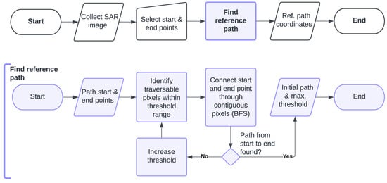
Figure 4.
Flowchart of reference path identification for application in ideal conditions. (Top) High-level flowchart for detection. (Bottom) Detailed flowchart showing Find reference path process.
3.2. All Conditions
In reference to the 2021 dataset of 60 SAR images, less than half of these would be suitable for the assumptions described for ideal conditions. This necessitates a robust channel detection algorithm for all conditions, presented in Figure 5, which relies on a memory of the previous channel path and knowledge of historic sand/mud locations. This algorithm operates with the assumption that the majority of the channel will be similarly located as in the previous image. This assumption is supported by the demonstrated efficacy of the algorithm, where the time between images is a matter of days: the 60 images in the 2021 dataset have a median separation of 3 days and a maximum of 20 days (see Section 2.3).
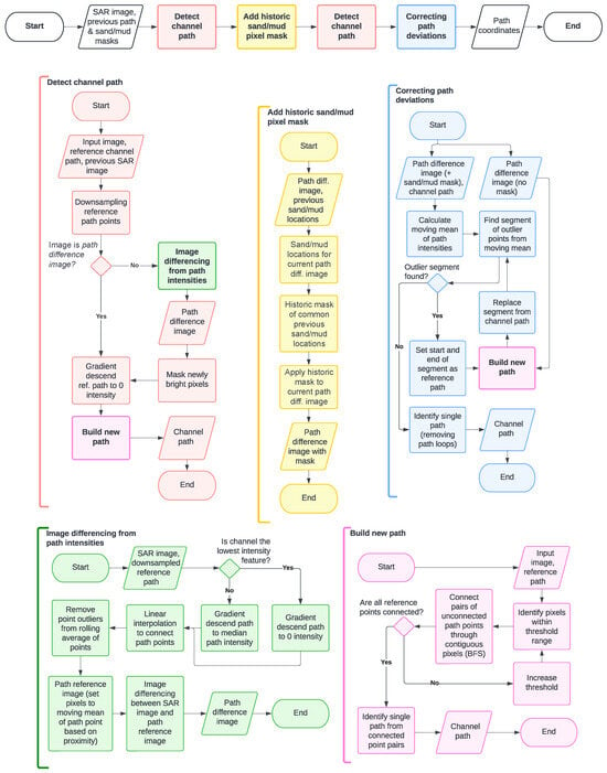
Figure 5.
Flowchart of channel path identification for application in all conditions.
An overview of the algorithm is displayed in the top of Figure 5 and summarised as follows:
- A channel path is detected (Detect channel path—Section 3.2.2) based on the previous path and a manipulated SAR image, referred to as a path difference image (Section 3.2.1).
- This initial channel path is then updated to account for historic sand/mud locations (Add historic sand/mud pixel mask—Section 3.2.4) such that the path avoids high-risk locations that have frequently been sand or mud.
- This updated channel path is edited to reroute any segments that overlay sand or mud in the current image (Correcting path deviations—Section 3.2.5).
The final step enables newly formed channels to be detected that traverse historical sand/mud areas. Again, we note that this approach requires knowledge of recent channel path locations. In the absence of previous path information, a reference path can either be defined for the current SAR image if it has been taken in ideal conditions using the algorithm in Section 3.1, or manually defined with a set of coordinates.
3.2.1. Path Difference Image
Due to the variation in tidal channel presentation in SAR images, based on conditions at the time of capture (see Figure 3), the creation of a path difference image, where the lowest-intensity pixels characterise the tidal channel, attempts to standardise the presentation of the tidal channel. This manipulated version of the SAR image is created by identifying the points from a reference path that likely represent the current channel and adjusting the image pixel intensities such that these channel points are the lowest-intensity pixels (i.e., emulating the appearance of the tidal channel in ideal conditions).
The first step when creating a path difference image is to identify whether the channel is the lowest-intensity feature in the image. In ideal conditions, the low-intensity pixels that form the tidal channel can be identified as the lowest-intensity peak in the pixel intensity distribution. In non-ideal conditions, the pixel intensities of the tidal channel can be notably higher than the lowest peak that is instead associated with the surrounding sand/mud. Such an example is shown in Figure 6, where the mean reference path intensity is notably higher than the lowest-pixel-intensity peak, which is associated with areas of sand/mud either side of the channel.
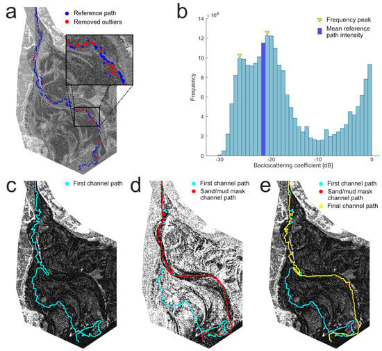
Figure 6.
Example of the channel path creation process for an SAR image on 04/12/2021. (a) Outlier points are removed from the reference path. (b) The mean reference path intensity is checked to see if it belongs to the lowest-intensity feature (i.e., in closest proximity to the lowest-intensity peak in the distribution). In this example, the peak that is closest to the mean ref. path intensity is not the lowest peak. (c) A path difference image is created, such that the lowest-intensity values are associated with the channel, and the first channel path is created. (d) The first channel path is updated after applying a sand/mud pixel mask. (e) A final channel path is created by correcting path deviations into high-intensity pixels in the path difference image. Copernicus Sentinel data 2021.
An important step in characterising the tidal channel is to check if the channel—as identified by the reference path—is associated with the lowest-intensity feature of the SAR image. This decision determines how the gradient descent is applied to the reference path. Gradient descent—an iterative optimisation algorithm used for finding the minimum of a function [30]—moves all reference path points towards either the lowest-intensity local minima for an ideal-conditions image or towards the median path intensity value when non-ideal conditions have been detected. For both cases, image smoothing and gradient descent are applied to move reference path points away from high-intensity features (e.g., sand banks) and towards the centre of low-intensity areas.
Following the gradient descent step, the downsampled reference path is upsampled by connecting each pair of path points with a straight line of evenly spaced points. This new reference path is then filtered to remove pixel intensity outliers as displayed in Figure 6. These outliers are identified as points outside of the standard deviation for the rolling average of the intensity. The rolling average varies with the length of the reference path, beginning at the start point and including previous points up to a quarter the length of the total reference path. The size of the rolling average provides a compromise between stability and allowing for intensity values to vary along the length of the channel. This rolling average also ignores any points with pixel intensities outside of the standard deviation for the previous points considered. In this way, an extended segment of the path overlaying sand/mud will not increase the rolling average. This is only an effective strategy if there is confidence that the initial path points lie on the river/tidal channel. In this paper, the channel path is considered to begin where the river meets the tidal flats; therefore, the initial stretch of channel is not prone to variation.
The remaining reference path points—those that were within one standard deviation of the rolling average—are then used to create a path reference image. This image assigns every pixel an intensity value that is equal to the closest reference path point. The absolute difference between the source SAR image and this path reference image produces a path difference image where the channel is characterised by the lowest-intensity pixels. The absolute difference is used as the sand/mud adjacent to the tidal channel can appear with lower or higher intensity than the channel depending on conditions. A path difference image is displayed in Figure 6c, where the source SAR image is shown in Figure 6a.
3.2.2. Detect Channel Path
The input to detecting the channel path is an input image, reference channel path, and the previous path difference image. The reference path is downsampled such that an evenly spaced subset of points are used to generate a new channel path. The source SAR image has to be manipulated as described in Section 3.2.1 to produce a path difference image.
A comparison with the most recent previous path difference image can reveal areas of notable intensity increase (i.e., newly bright pixels in Figure 5), as pixels representing the channel should be consistently low-intensity regardless of conditions. Areas with a large recent increase in intensity can represent a change from a deep water channel to a sandbank and are therefore masked (setting their pixel values to the highest intensity) to facilitate the route in avoiding emerging hazardous regions.
The final step before building a new channel path is to perform gradient descent on each reference path point, such that the points are moved towards a local pixel intensity minimum. At this stage, the reference path is supplied to Build new path (Section 3.2.3) to produce a channel path that follows a tidal channel from the river out to the estuary.
3.2.3. Build New Path
Building a new path from a reference path requires an input path difference image. A threshold is then applied, such that only pixels with intensity values equal to or less than the threshold value are included as navigable when constructing a path. The threshold is initially minimal, such that only the lowest pixel intensities remain. A new path is constructed by connecting the points on the reference path using navigable pixels. For each unconnected reference path point, an attempt is made to connect it to a downstream point (starting with the closest downstream point) through a contiguous (vertically or horizontally adjacent) set of pixels. If, after attempting to connect all reference path points, there remains unconnected points then the threshold is increased and the process repeats.
After each attempt to connect reference path point pairs with a path segment, the reference points are reviewed for removal. All reference points that lie between the beginning and end of a newly created path segment are removed, as this new section bypasses them. In addition, each fully connected reference point is removed. The definition for a fully connected point is that it is both the origin for a path segment and the destination for a separate path segment. The start and end points of the reference path are exempt from this requirement as they will only ever act as an origin or destination, respectively.
Once all pairs of remaining reference points have been connected through a contiguous pixel path found with a breadth-first search (as in Section 3.1), a single path from the start to end reference points is identified. This single path removes redundant path segments (e.g., loops) and disconnected path segments from the channel path. It is again found using a breadth-first search applied from start to end points.
Note that this is distinct from the creation of a reference path, displayed in Figure 4, where there are only two reference points to connect, namely, the start and end points of the path.
3.2.4. Add Historic Sand/Mud Pixel Mask
Sand/mud locations are identified from the path difference images using a single threshold value, where lower-intensity pixels have a similar backscattering coefficient to the nearest reference channel path point (as defined in Section 3.2.1). The threshold value is empirically defined as 7.8 dB, which is a conservative threshold (see Figure 6b), including pixels that are likely to represent sand or mud in the tidal flat.
The sand/mud locations identified in the current image are considered alongside those detected in previous images to detect common historic sand/mud locations. For this work, the previous four images were used for this process of historic sand/mud identification. Due to the relative regularity of SAR image collection for the target region in the Solway Firth, these four historic images equate to a relatively consistent time window of around one month prior to the current image. If a pixel is more often sand/mud than water in these five images (four historic, one current), then a mask is applied to that pixel. An example path difference image is shown in Figure 6c,d, which shows the same image after applying a historic sand/mud pixel mask. In this example, the first channel path traverses regions that were historically sand/mud. The channel path identification algorithm (see Figure 5) creates this initial channel path, before adding the historic sand/mud pixel mask and recalculating a channel path (sand/mud mask channel path in Figure 6) that avoids historic sand/mud areas.
3.2.5. Correcting Path Deviations
A moving average (mean) of the channel path intensities is calculated [31] for the path difference image with historic sand/mud mask to find path segments of outlier points (i.e., intensities outside of one standard deviation of the moving average). Each outlier segment is replaced by taking the start and end points of the segment as reference points, for building a new path (Build new path—Section 3.2.3) based on the path difference image without the sand/mud mask applied. This process enables new channels to be found that were not historically navigable, due to mud and sand, as identified by the historic sand/mud mask. The example in Figure 6e displays only a minor adjustment when creating the final channel path.
3.3. Validating SAR Images
Channel paths were followed and depth measurements were taken around them by the Nith Inshore Rescue team on the 28 February 2021 and the 26 July 2022. The team took depth measurements at different points along the channel paths, created using the method presented in Section 3.2. These measurements were taken with a Raymarine RV100 sonar transducer with the depths reported on a touchscreen (Axiom MFD) alongside a visualisation of the boat’s position according to GPS. Figure 7 presents the results for the depth tests, superimposed on SAR images acquired on the day of test. Note that each SAR image was taken from the day of the test, but at a lower tide height than when the team performed measurements. The depth recordings support our visual interpretation of the SAR images, where deeper locations match with the channel path and the shallow locations are associated with brighter areas of the image that we associate with raised sand/mud banks.
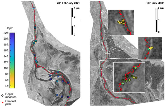
Figure 7.
Depth recordings from two channel path validation exercises, carried out by the Nith Inshore Rescue on (left) the 28 February 2021 and (right) the 26 July 2022. Copernicus Sentinel data 2021 & 2022.
The depth measurement locations on the 28 February 2021 are associated with exact GPS positions, while the locations on the 26 July 2022 were approximated from recordings of the onboard navigation touchscreen.
The results of these tests support the accuracy and relevance of the SAR imagery in determining channel height, where the lowest depths correspond with high-intensity pixels in the SAR image. The depth measurements close to the channel path are generally the deepest, with the channel seen to become deeper the further away from the river feeding into the tidal channel.
4. Methods—Data Analysis
4.1. Supporting Data
A variation in how tidal flats are presented in SAR images is expected since previous studies have suggested that the non-ideal conditions altering tidal zone presentation are a consequence of weather and tidal conditions, in particular high wind speeds and the tidal phase [9,13]. Identifying the most impactful phenomena for the Solway Firth region could help inform future mapping activities and provide information about the reliability of routes generated from SAR imagery based on the conditions at the time of acquisition. For this investigation, weather and tidal data were gathered for the 60 SAR images used to detect channel paths in 2021 (see Section 2.3). These data included wind speed, rainfall, time since high tide, and tide height.
Hourly weather data (wind speed and atmospheric pressure) for the region of interest were obtained via the Meteostat service https://meteostat.net/ (accessed on 10 March 2023), which provides open-source historical weather data from NOAA and other organisations. Data for a chosen location were based on interpolation between available weather stations to provide historical weather information for a given location. The location used herein was Glencaple (54.92°N, 3.54°W).
Rainfall accumulation data are available from the MET office [32], where the accumulation of rainfall was considered for the preceding 6 h prior to image collection for the Dumfries Weather observation site (MET office ID: 957966001).
The tide height considered is recorded at Workington Station (54.65°N, 3.57°W), and acquired from the British Oceanographic Data Centre (BODC) [28]. The historical tide heights as measured against the Admirality Chart Datum are provided by the BODC at 15 min intervals for Workington. Tidal residuals is a metric calculated as the observed sea level value minus the predicted tide, where residuals are dependent on a combination of wind speed, air pressure, and storm surges [33].
The River Nith is the main tributary to the tidal channel considered throughout this paper, with the impact of river flow on tidal channels investigated here. River flow data were acquired for the River Nith at Friars Carse (station ID: 133156) from the API provided by the Scottish Environment Protection Agency (SEPA) [34].
4.2. Data Analysis
To evaluate the impact of weather, river, and tidal variation on the SAR presentation of tidal flats and channels, pixels were monitored for the tidal channel and tidal flat to provide representative values. For the tidal channel, the median intensity—from the points that define the channel path for a given image—was taken as the SAR tidal channel pixel intensity. For the tidal flats, ten points were defined in areas that were consistently sand/mud during 2021 as shown in Figure 8. A 20-by-20 grid of pixels at each of these ten points were sampled for a median-filtered image.
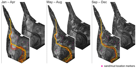
Figure 8.
Channel paths detected during 2021 overlaid on averaged path difference image of the tidal flat for (Left) January–April, (Centre) May–August, and (Right) September–December. Channel paths are coloured chronologically from red to yellow for each time period. Sand/mud location markers are also shown to indicate areas of consistent sand/mud coverage during 2021. Copernicus Sentinel data 2021.
The median value from this set of pixels was used to define the SAR tidal flat pixel intensity.
Correlations were evaluated between SAR tidal channel pixel intensities, SAR tidal flat pixel intensities, weather, river, and tidal data for the images collected in 2021. These data series were investigated with Pearson’s correlation coefficient to provide a measure of their linear independence.
5. Results
5.1. Channel Path Accuracy
The tidal channel path detection algorithm, introduced in Section 3.2, is applied to create a route from the River Nith to the Solway Firth that navigates the tidal flats. The full collection of individual channel paths is included in the supplementary materials, alongside a visual assessment of path errors. A path error denotes a section of the channel path that traverses an area of sand/mud. Errors are identified in 16.7% of the images (83.3% without errors, 50 from the set of 60), with one error found in 9 images and two errors in 1 image. These errors are detailed in the supplementary materials where they can be seen to be largely minor deviations from the channel often in areas of low clarity between a channel and tidal flat.
The channel path detection algorithm presented in Figure 5 includes a historic sand/mud mask and a step for correcting path deviations. Both are found to reduce the error rate on channel paths detected, where excluding the historic sand/mud masks results in more path errors (a total of 34, compared to 11 total errors when the historical data are used) and a greater frequency of errors (errors in 38.3% of images, compared to 16.7% when the historical data are used). If the correcting path deviations step is then removed, the number of errors remains at 34 but the error rate rises further to 43.3% of images. Also note that the historic sand/mud mask is not only influential in reducing the quantity of errors but also in reducing their scale, preventing large deviations such as the example shown in Figure 6.
Existing methods of ship navigation predominantly consider known environments with identified obstacles; applying efficient but similar methodologies to BFS such as Ant Colony optimisation and A* search [19]. For navigation through tidal flats based on SAR imagery, the challenge lies in the recognition of obstacles versus traversable channels. Therefore, directly applying the BFS results without adjusting the image results in 106 errors across 71.7% of the images tested.
A Pearson’s correlation of wind speed and the number of errors demonstrates that the errors from directly applying BFS correspond to high wind speed ( , ). While far fewer errors are present in the full algorithm, a relationship between errors and wind speed is still present (, ).
5.2. Channel Variation over a Year
The 60 channel paths created from 2021 are displayed in Figure 8, where the paths are separated into four-month periods alongside an averaged path difference image of the tidal flats during that time. By monitoring the tidal paths over one year, it is possible to observe triggering events for changes in the path’s route out to the Solway Firth. Figure 8 presents evidence of periods of relative consistency interjected by two major shifts in the channel location. Tidal channels experience continuous change, but Figure 9 provides evidence that periods of exceptionally high river flow can trigger sudden major changes.
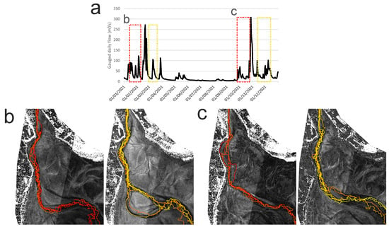
Figure 9.
Changes in tidal channels are observed after periods of high river flow. (a) Two periods of high river flow (gauged daily flow) are identified with peaks on 20 February and 28 October 2021. Either side of these peaks are periods of satellite observation marked by boxes in (a) and displayed in (b,c). (b) Channel path detected (left) from 14/01/21 to 09/02/21 and (right) from 25/02/21 to 17/03/21. (c) Channel path detected (left) from 19/09/21 to 24/10/21 and (right) from 07/11/21 to 07/12/21. Channel paths are coloured chronologically from red to yellow for (b,c). Copernicus Sentinel data 2021.
Figure 9a demonstrates that two of the most obvious changes in the tidal channel in 2021 are associated with the two highest-river-flow periods that year. The channel paths in b and c depict the periods of time before and after periods of high river flow, with the associated time periods shown in a. In Figure 9b, a minor route that was visible before 20/02/21 becomes a main direct path for the channel. In Figure 9c, the shape of the channel has notably altered; after heavy river flow, a wider channel and more consistent path locations are observed for the top half of the image that leads to a change in trajectory for the rest of the channel path.
5.3. Conditions Influencing SAR Images
A variability in SAR imagery was highlighted earlier in Figure 3 and is anticipated for the tidal channel in high-wind conditions [13] and for tidal flat sands for tidal phase (ebb and flood) and water level history, e.g., the time and level of the closest low tide [9]. The partial Pearson’s correlation of these SAR intensity variations, for both the tidal channel and the sand/mud of the tidal flat, with wind speed, time since high tide, tide heights, and SAR incidence angle variables are detailed in Figure 10. Other weather variables, such as rainfall, tidal residuals, and air pressure, were not included, as they were not found to significantly correlate with tidal flat or channel presentation when controlling for the effect of wind speed. It is worth noting that the tidal measurements are spatially (30 km south) and therefore also temporally distant from the area of the Solway Firth investigated, which could reduce the magnitude of correlation coefficients.
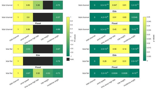
Figure 10.
Partial correlation coefficients R (left) and corresponding p values (right) report the strength/direction and statistical significance of the linear relationship between SAR pixel intensities, which characterise tidal channel and tidal flat, with wind speed, time since high tide, tide height, and SAR incidence angle while controlling for the influence of the other variables. The partial correlations are displayed for all 60 images in 2021 involved in channel path detection. For tidal flat, partial correlations are identified for a subset of 26 images taken as water levels decrease (ebb) and 34 images as water levels increase (flood). Only significant correlation coefficients r are displayed and the colour range is constrained such that values are all yellow.
The SAR incidence angle denotes the angle of the incident microwave radiation and is known to influence the backscattering coefficient; therefore, it is consistently correlated with tidal flat and tidal channel presentation in SAR imagery.
5.3.1. Tidal Channel
The prominent relationship between tidal channel presentation and wind speed is evident in Figure 10, where high winds increase water surface roughness and, hence, the backscattering coefficient. The correlation between tidal channel and time since high tide is only reported for the analysis of all images and even then with a high p value of 0.047. High wind speeds result in a higher backscattering coefficient, while higher incidence angles correspond to a lower backscattering coefficient.
5.3.2. Tidal Flat
Wind speed and SAR incidence angle are also found to have prominent influences on tidal flat presentation, where higher wind speeds and higher incidence angles both correspond to a lower backscattering coefficient for tidal flats. Notably, the tide phase is influential on how other conditions affect tidal flat presentation. There is a stark contrast in wind speed’s influence on tidal flat presentation between ebb and flood phases. During the ebb phase, when waters are receding from sand/mud areas, the wind has no notable relationship with SAR intensities across the tidal flats (), while during the flood phase, as the waters rise, there is a clear correlation (). During the flood phase, the wind speed, time since high tide, tide height, and incidence angle all correlate with tidal flat SAR presentation. Time since high tide indicates the time exposed to air for sand/mud areas, where a longer time since high tide when in the flood phase corresponds to a higher backscattering coefficient. A higher tide height in the flood phase corresponds with a lower backscattering coefficient.
5.3.3. Case Study of Changing Conditions
A case of changing weather conditions over four consecutive days is presented in Figure 11 for an eastern region of the Solway Firth highlighted in Figure 1. The peak wind speeds present in the first image decreases over the four days, with the SAR representation of the intertidal zone appearing to respond to the changing conditions. The images were taken in similar temporal proximity to high tide; hence, sand exposure to air would be similar, with a time since high tide of approximately 6 h 45 min (28/03/21), 7 h (29/03/21), 6 h 15 min (30/03/21), and 5 h 45 min (31/03/21). The typical representation of the sand/mud and tidal channel in ideal conditions is seen in the final image of Figure 11 for 31/03/21 where the sand/mud has higher-intensity values than the low-intensity tidal channel. The incidence angle is seen to be at its highest on 31/03/21, which contributes to the low-intensity tidal channel but, as shown in Figure 10, low-intensity tidal flats would also be expected. Although not detected as a significant and distinct influence on SAR presentation, the rainfall (over 12 h prior to each image) does decrease over the four days with 7.4 mm, 3 mm, 0 mm, and 0 mm recorded, respectively. This series of images highlights how rapidly tidal zone SAR presentation can vary and how susceptible these images are to the conditions at image capture.
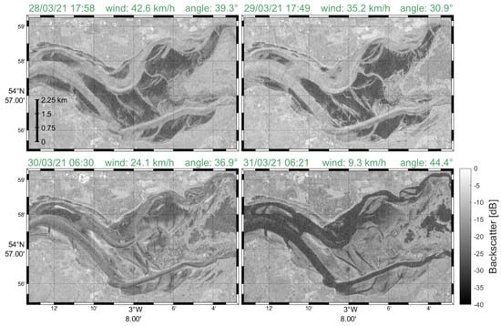
Figure 11.
A series of SAR images from the Solway Firth for the (top left) 28th, (top right) 29th, (bottom left) 30th, and (bottom right) 30st March 2021. Each image is taken during the ebb phase or at low tide. The decreasing wind speed over the four days and the SAR incidence angle are marked on each image, alongside notable changes in the presentation of tidal channels and the surrounding tidal flats. Copernicus Sentinel data 2021.
6. Nith Inshore Rescue Application
Historically, Nith Inshore Rescue would rely on periodic depth measurements along their route from Glencaple out towards the Solway Firth, aided by visual inspection of channel positions at low tide. Their lifeboat is fitted with a Raymarine sonar system and chartplotter; the former provides depth measurements and the latter is able to record previous routes, as well as upload routes in the form of the GPS Exchange Format (GPX).
The presented technique is implemented by Nith Inshore Rescue by first acquiring the latest satellite-based SAR imagery in low-tide conditions. A safe passage channel path is generated using the described technique and overlaid on the image, allowing the team to visually review the proposed path before uploading it to the Raymarine chartplotter in a GPX format. The Raymarine system provides a heading towards each waypoint along a route depicting the best navigational channel that, when following the route, automatically updates upon close approach to provide a heading to the next and subsequent waypoints. To avoid continuous navigation updates, a downsampled set of waypoints are provided with at least 30 times larger spacing than the waypoints in the full channel path. In addition, the sequence of waypoints are visualised on the digital nautical chart to advise on the channel location such that the Nith Inshore Rescue can use this insight in combination with knowledge of the area, current tides, and known hazards to pick and choose which waypoint in the sequence to head to next both for safety and best speed; hence, the waypoints are often not followed in a linear sequence from start to end.
The visual assessment of the channel paths included in the supplementary materials highlights the occurrences of close approaches to the channel banks where the rescue team would likely use their local knowledge and judgement to determine whether they follow the path exactly.
7. Discussion
Detecting visually accurate channel paths over a year demonstrates the efficacy of using readily available SAR imagery to find tidal channel paths, providing sufficiently frequent and unobscured imagery to monitor a dynamic tidal zone environment. There are still challenges associated with using SAR imagery. These include variations between images in different conditions and variations within images that disguise the boundaries between channel and sand, due to factors such as wind, turbulent water flow, and wet sand/mud. The path detection algorithm, presented herein, supports path routing in variable SAR images by relying on previous knowledge of the channel location. As a result, the algorithm is at greatest risk to produce errors following a series of images where there is reduced clarity between tidal zone features, which consequently reduces the reliability of the sand/mud mask used to indicate areas of sand/mud in previous images. This paper demonstrates the efficacy of this approach, where knowledge of previous sand/mud locations enables accurate channel path detection for 60 images separated by a median period of 3 days up to a maximum of 20 days (see Section 2.3). This represents an improvement in the accuracy and the number of images that can be used for path generation, over similar methodologies that do not apply image and path correction steps.
High wind shear is known to affect water’s presentation in SAR imagery [13]. In addition, wind can generate waves of comparable size to the wavelength of the SAR signal, known as Bragg waves, that lead to strong backscatter signals. However, the influence of wind on sand flats has not been similarly acknowledged where previous work found no influence on sand flat presentation with SAR [9]. We found a clear correlation in flood phase (), but no relationship between wind speed and tidal flat presentation in the ebb tidal phase (). It is possible that the wind’s influence on SAR imagery for the region of interest here is due to the transportation of water spray from tidal channels. The lack of correlation in the ebb phase is potentially due to the greater saturation of water in sand/mud areas that, due to recent submersion, diminishes the influence of wind speed.
By identifying channel paths over a year, this work supports our understanding of these channels by demonstrating an expected relationship between periods of high river flow and changes in the tidal channel. Specifically, periods of high river flow are responsible for step changes in the shape of the channel. The role of river flow in shaping tidal channels and transporting sediment has been studied for similarly dynamic tidal environments [35,36]. Tidal channels are continuously shifting, with the risk that the channel path no longer accurately maps the current tidal channel increasing with the time since image collection. But this risk notably increases following a high river flow, which usually follows a period of heavy rainfall or snow melt. These are relationships that are expected, but the work of this paper provides the tools to track these changes and improve the safety of those operating in intertidal zones. This is research of particular importance to our collaborators Nith Inshore Rescue who have provided informal feedback on the channel paths routinely provided to their team as well as completing formal validation exercises as captured in Figure 7.
8. Conclusions
Synthetic Aperture Radar (SAR) imagery is a valuable tool for mapping dynamic natural areas, such as tidal zones. Images taken at low tide can reveal the structure and location of tidal channels; however, the automatic detection of tidal channels is challenging due to variations in SAR imagery. Tidal channel presentation in SAR images is known to be susceptible to wind speed, but we found that the sand/mud in tidal flats is also influenced by wind speed among other tidal conditions. To mitigate against variations of SAR imagery, we developed a path routing algorithm that references previous sand and mud locations to inform the creation of a channel path for a given SAR image. This method has proven effective in mapping channel locations and has provided valuable support to the operation of the Nith Inshore Rescue service in the Solway Firth.
Supplementary Materials
The following supporting information can be downloaded at: https://www.mdpi.com/article/10.3390/rs16061057/s1.
Author Contributions
Conceptualization, R.A.C., C.N.M., G.G. and M.M.; methodology, R.A.C., C.N.M., A.A.W. and M.M.; software, R.A.C. and A.A.W.; validation, R.A.C., C.N.M. and G.G.; formal analysis, R.A.C.; investigation, R.A.C., C.N.M., A.A.W. and M.M.; writing—original draft preparation, R.A.C. and C.N.M.; writing—review and editing, R.A.C., C.N.M., A.A.W., C.J.L., G.G. and M.M.; funding acquisition, R.A.C., C.N.M., G.G. and M.M. All authors have read and agreed to the published version of the manuscript.
Funding
This work was supported in part by an Innovation Voucher from the Scottish Funding Council.
Data Availability Statement
SAR imagery is available from Google Earth Engine, with the specific scripts used herein available at [21]. The implementation of the algorithms described herein are available at [29]. Hourly weather data (wind speed, atmospheric pressure) for the region of interest are obtained via the Meteostat service https://meteostat.net/ (accessed on 10 March 2023). River flow data were therefore acquired for the river Nith at Friars Carse (station ID: 133156) from the API provided by the Scottish Environment Protection Agency (SEPA) [34]. Rainfall accumulation data are available from the MET office [32]. Tide height and residuals considered here are recorded at Workington Station (54.65°N, 3.57°W), from the British Oceanographic Data Centre (BODC) [28].
Acknowledgments
This study uses data from the National Tidal and Sea Level Facility, provided by the British Oceanographic Data Centre and funded by the Environment Agency. Satellite imagery is provided by the European Space Agency via the Copernicus Service.
Conflicts of Interest
The authors declare no conflicts of interest.
References
- NASA Goddard Space Flight Center. MODIS Image of the Day, 2012-06-04. 2012. Available online: https://modis.gsfc.nasa.gov/gallery/individual.php?db_date=2012-06-04. (accessed on 27 March 2023).
- OceanWise, Using: EDINA Marine Digimap Service. Raster CHARTS [TIFF Geospatial Data], Scale 1:50000, Tiles: 1344-0, 2013-1, 2013-2, 2013-3, 2013-4, 2013-5, 2198-1,1320-0, 1346-0, 2013-0, 2093-0, 2094-0, 2198-0, 2199-0, 0002-0, 1121-0, 1411-0, 1826-0, 2182B-0, 2635-0, 2724-0. Downloaded: 2020-08-25 12:34:08.703, Updated: 16 July 2020. Available online: https://digimap.edina.ac.uk (accessed on 1 February 2023).
- Healy, T.; Wang, Y.; Healy, J.A. Muddy Coasts of the World: Processes, Deposits and Function; Elsevier: Amsterdam, The Netherlands, 2002. [Google Scholar]
- McFeeters, S.K. The use of the Normalized Difference Water Index (NDWI) in the delineation of open water features. Int. J. Remote Sens. 1996, 17, 1425–1432. [Google Scholar] [CrossRef]
- McGrath, C.N.; Clark, R.A.; Ilioudis, C.; Gibbons, G.; McKee, D.; Clemente, C.; Macdonald, M. Mapping of shifting tidal estuaries to support inshore rescue. In Proceedings of the Remote Sensing of the Ocean, Sea Ice, Coastal Waters, and Large Water Regions 2020, Online, 21–25 September 2020; SPIE: Bellingham, WA, USA, 2020; Volume 11529, p. 1152903. [Google Scholar]
- McGrath, C.N.; Cowley, D.C.; Hood, S.; Clarke, S.; Macdonald, M. An assessment of high temporal frequency satellite data for historic environment applications. A case study from Scotland. Archaeol. Prospect. 2022, 30, 267–282. [Google Scholar] [CrossRef]
- Donato, T.F.; Lyzenga, D.R.; Yan, X.H. A comparative analysis of Landsat TM and radarsat SAR signatures in restricted tidal channels. In Proceedings of the IEEE International Geoscience and Remote Sensing Symposium, Toronto, ON, Canada, 24–28 June 2002; IEEE: Piscataway, NJ, USA, 2002; Volume 5, pp. 2841–2843. [Google Scholar]
- Van der Wal, D.; Herman, P.M.; Ysebaert, T. Space-borne synthetic aperture radar of intertidal flat surfaces as a basis for predicting benthic macrofauna distribution. EARSeL EProceed. 2004, 3, 69–80. [Google Scholar]
- Gade, M.; Wang, W.; Kemme, L. On the imaging of exposed intertidal flats by single-and dual-co-polarization Synthetic Aperture Radar. Remote Sens. Environ. 2018, 205, 315–328. [Google Scholar] [CrossRef]
- Yang, W.; Sha, J.; Bao, Z.; Dong, J.; Li, X.; Shifaw, E.; Tan, J.; Sodango, T.H. Monitoring tidal flats boundaries through combining Sentinel-1 and Sentinel-2 imagery. Environ. Technol. Innov. 2021, 22, 101401. [Google Scholar] [CrossRef]
- Liu, G.; Liu, B.; Zheng, G.; Li, X. Environment monitoring of Shanghai Nanhui intertidal zone with dual-polarimetric SAR data based on deep learning. IEEE Trans. Geosci. Remote Sens. 2022, 60, 1–18. [Google Scholar] [CrossRef]
- Pardo, B.L.; Clark, R.A.; Gibbons, G.; MacDonald, M.; McGrath, C.N. Tracking shifting estuaries with remote sensing techniques to aid lifeboat rescue services. In Proceedings of the Remote Sensing of the Ocean, Sea Ice, Coastal Waters, and Large Water Regions 2023, Amsterdam, The Netherlands, 3–7 September 2023; SPIE: Bellingham, WA, USA, 2023; Volume 12728, pp. 62–71. [Google Scholar]
- Alsdorf, D.E.; Rodríguez, E.; Lettenmaier, D.P. Measuring surface water from space. Rev. Geophys. 2007, 45. [Google Scholar] [CrossRef]
- Zhang, S.; Xu, Q.; Zheng, Q.; Li, X. Mechanisms of SAR imaging of shallow water topography of the Subei Bank. Remote Sens. 2017, 9, 1203. [Google Scholar] [CrossRef]
- Gulácsi, A.; Kovács, F. Sentinel-1-imagery-based high-resolution water cover detection on wetlands, Aided by Google Earth Engine. Remote Sens. 2020, 12, 1614. [Google Scholar] [CrossRef]
- Chang, K.Y.; Jan, G.E.; Parberry, I. A method for searching optimal routes with collision avoidance on raster charts. J. Navig. 2003, 56, 371–384. [Google Scholar] [CrossRef]
- Szlapczynski, R. A new method of ship routing on raster grids, with turn penalties and collision avoidance. J. Navig. 2005, 59, 27–42. [Google Scholar] [CrossRef]
- Sadik, A.M.; Dhali, M.A.; Farid, H.M.; Rashid, T.U.; Syeed, A. A comprehensive and comparative study of maze-solving techniques by implementing graph theory. In Proceedings of the 2010 International Conference on Artificial Intelligence and Computational Intelligence, Sanya, China, 23–24 October 2010; IEEE: Piscataway, NJ, USA, 2010; Volume 1, pp. 52–56. [Google Scholar]
- Zhang, Y.; Wen, Y.; Tu, H. A Method for Ship Route Planning Fusing the Ant Colony Algorithm and the A* Search Algorithm. IEEE Access 2023, 11, 15109–15118. [Google Scholar] [CrossRef]
- European Union/ESA/Copernicus. Sentinel-1 SAR GRD: C-Band Synthetic Aperture Radar Ground Range Detected, Log Scaling. 2023. Available online: https://developers.google.com/earth-engine/datasets/catalog/COPERNICUS_S1_GRD (accessed on 7 December 2023).
- Clark, R. SAR_tidal_channels (v1.0). 2023. Available online: https://zenodo.org/records/7799365 (accessed on 7 December 2023).
- NASA. Land/Water Mask Algorithm Specification. SeaDAS, n.d. Available online: https://seadas.gsfc.nasa.gov/help-8.2.0/watermask/WatermaskAlgorithmSpecification.html (accessed on 7 December 2023).
- European Space Agency SNAP-Sentinel Application Platform, Version 9.0.0; [Software]; European Space Agency: Paris, France, 2022.
- Gade, M.; Alpers, W.; Melsheimer, C.; Tanck, G. Classification of sediments on exposed tidal flats in the German Bight using multi-frequency radar data. Remote Sens. Environ. 2008, 112, 1603–1613. [Google Scholar] [CrossRef]
- Geudtner, D.; Torres, R.; Snoeij, P.; Davidson, M.; Rommen, B. Sentinel-1 system capabilities and applications. In Proceedings of the 2014 IEEE Geoscience and Remote Sensing Symposium, Quebec City, QC, Canada, 13–18 July 2014; IEEE: Piscataway, NJ, USA, 2014; pp. 1457–1460. [Google Scholar]
- European Space Agency. Mission ends for Copernicus Sentinel-1B Satellite. 2023. Available online: https://www.esa.int/Applications/Observing_the_Earth/Copernicus/Sentinel-1/Mission_ends_for_Copernicus_Sentinel-1B_satellite (accessed on 27 March 2023).
- European Space Agency. Ride into Orbit Secured for Sentinel-1C. 2023. Available online: https://www.esa.int/Applications/Observing_the_Earth/Copernicus/Sentinel-1/Ride_into_orbit_secured_for_Sentinel-1C (accessed on 27 March 2023).
- British Oceanographic Data Centre. UK Tide Gauge Network Data-Processed. 2023. Available online: https://www.bodc.ac.uk/data/hosted_data_systems/sea_level/uk_tide_gauge_network/processed/ (accessed on 27 March 2023).
- Clark, R. Monitoring_Tidal_Channels, Version v1.0; Zenodo: Geneva, Switzerland, 2023. [CrossRef]
- Ruder, S. An overview of gradient descent optimization algorithms. arXiv 2016, arXiv:1609.04747. [Google Scholar]
- MathWorks. Moving Mean. Code Used in Research: MATLAB Code for Moving Mean. 2023. Available online: https://uk.mathworks.com/help/matlab/ref/movmean.html (accessed on 27 March 2023).
- Met Office. Met Office WOW-Weather Observation Website. 2023. Available online: https://wow.metoffice.gov.uk/observations/details?site_id=957966001 (accessed on 27 March 2023).
- National Oceanography Centre. Marine Data Products: Meteorological Effects on Tidal Predictions. 2023. Available online: https://noc.ac.uk/files/documents/business/Tides-and-Meteorological-Effects.pdf (accessed on 27 March 2023).
- Scottish Environment Protection Agency. Scottish Environment Protection Agency API. 2023. Available online: https://timeseriesdoc.sepa.org.uk/api-documentation/ (accessed on 27 March 2023).
- Xie, D.; Pan, C.; Gao, S.; Wang, Z.B. Morphodynamics of the Qiantang Estuary, China: Controls of river flood events and tidal bores. Mar. Geol. 2018, 406, 27–33. [Google Scholar] [CrossRef]
- Xie, D.; Wang, Z.B.; Huang, J.; Zeng, J. River, tide and morphology interaction in a macro-tidal estuary with active morphological evolutions. Catena 2022, 212, 106131. [Google Scholar] [CrossRef]
Disclaimer/Publisher’s Note: The statements, opinions and data contained in all publications are solely those of the individual author(s) and contributor(s) and not of MDPI and/or the editor(s). MDPI and/or the editor(s) disclaim responsibility for any injury to people or property resulting from any ideas, methods, instructions or products referred to in the content. |
© 2024 by the authors. Licensee MDPI, Basel, Switzerland. This article is an open access article distributed under the terms and conditions of the Creative Commons Attribution (CC BY) license (https://creativecommons.org/licenses/by/4.0/).