Abstract
2D-3D registration is increasingly being applied in various scientific and engineering scenarios. However, due to appearance differences and cross-modal discrepancies, it is demanding for image and point cloud registration methods to establish correspondences, making 2D-3D registration highly challenging. To handle these problems, we propose a novel and automatic solution for 2D-3D registration in Manhattan world based on line primitives, which we denote as VPPnL. Firstly, we derive the rotation matrix candidates by establishing the vanishing point coordinate system as the link of point cloud principal directions to camera coordinate system. Subsequently, the RANSAC algorithm, which accounts for the clustering of parallel lines, is employed in conjunction with the least-squares method for translation vectors estimation and optimization. Finally, a nonlinear least-squares graph optimization method is carried out to optimize the camera pose and realize the 2D-3D registration and point colorization. Experiments on synthetic data and real-world data illustrate that our proposed algorithm can address the problem of 2D-3D direct registration in the case of Manhattan scenes where images are limited and sparse.
1. Introduction
Laser-scanning point clouds have been widely utilized in fields such as deformation monitoring [1,2,3], disaster management assessment [4,5,6], smart city construction [7,8,9], and others. Three-dimensional point cloud data offer advantages of large scale and high precision, but they lack sufficient texture information. By integrating complementary information from different sensors, it is possible to obtain spatial scene data with richer details, providing better representations of target structures [10,11]. For instance, combining point clouds with optical images can create 3D models with color textures [12,13]. Similarly, merging point clouds with thermal images can produce 3D thermal texture models, which facilitates the rapid spatial localization of heat leakage areas [14,15]. Consequently, 2D-3D registration can provide richer multi-dimensional information for 3D spatial structures and is widely used in various scientific and engineering scenarios.
However, due to appearance and cross-modal differences, it is difficult to obtain correspondences in images and point clouds, making 2D-3D registration extremely challenging [16]. Extensive research has been conducted on the issue of 2D-3D registration, and the current relevant research results can be divided into three schemes.
The first scheme involves generating dense point clouds based on dense image matching with large overlap, and then using the iterative closest point (ICP) algorithm [17] or its improved versions [18,19] to match the dense point cloud with the original point cloud. Essentially, this scheme converts the 2D-3D data fusion problem into a point cloud registration problem, which is widely used for registration between aerial photographs and point clouds [20,21,22]. The dense image point clouds derived from aerial photographs provide large-scale 3D data for geographic information systems and smart city construction. However, there are some challenges with this scheme. Firstly, when processing point clouds in large-scale complex scenes, the ICP algorithm is inefficient and sensitive to the iteration’s initial values, which may result in a local optimal solution. In addition, this 2D-3D registration scheme requires a large amount of dense images with high overlap to generate dense image point clouds, not suiting for registration between single or sparse images and point clouds.
The second scheme is transforming 3D laser point clouds into 2D images with the intensity value or elevation value, and then achieve registration between point clouds and images by finding the same kind of descriptors [23,24], e.g., Scale-Invariant Feature Transform (SIFT) [25], Speeded-Up Robust Features (SURF) [26], oriented FAST and rotated BRIEF (ORB) [27], Harris corner descriptor [28], etc. This scheme achieves registration by converting point clouds into images, while some information of point clouds will be lost during the conversion process. Meanwhile, due to the sensitivity of image feature descriptors to changes in lighting and weather, it is difficult to remain stable and reliable for 2D-3D registration methods based on image descriptors.
The third scheme is directly establishing 2D-3D registration with cross-modal geometric feature primitives, since there are several 2D features that are consistent with 3D geometric structures, such as corner points, edge lines, planes, and so on [29]. Therefore, the consistent properties of cross-modal geometric features can be exploited to find correspondences. This scheme avoids the process of 3D image reconstruction or finding the same descriptors, achieving 2D-3D registration through only one single image, while it is less automated. Moreover, simple geometric features, such as point features, need careful design to maintain the ability to co-occur across modalities.
Given the challenges in achieving automatic and robust registration based on single image and point cloud data, an automatic solution for 2D-3D registration in Manhattan world using line primitives (which we refer to as VPPnL) is presented. We first calculate the rotation candidates between the point cloud coordinate system and the camera coordinate system. This calculation leverages the characteristic that the direction of the line connecting the camera’s optical center to the vanishing point aligns with the direction of parallel lines in 3D scenes, under the Manhattan hypothesis. Subsequently, we apply the Random Sample Consensus (RANSAC) [30] algorithm, considering groups of line segments clustered by vanishing points, to obtain the optimal translation vector for each rotation candidate. This process enables the automatic calculation of a rough camera pose. Finally, we determine the 2D-3D corresponding lines from the rough camera pose and optimize the camera pose using nonlinear least-squares graph optimization, mapping the pixel colors into 3D points and generating the texture 3D models.
The contributions of this study are as follows:
- A robust and automatic workflow is provided for calculating rotation matrix candidates between the camera coordinate system and the point cloud coordinate system, leveraging vanishing point directions under the Manhattan hypothesis.
- A novel strategy for determining translation vectors is proposed by fusing the clustering of parallel line segments into the least squares and the RANSAC algorithms, which significantly reduces the computational cost required for iterations.
- Considering the distance from 3D endpoints to the plane composed of the camera optical center and 2D line segments, a precise, efficient and globally optimal solution for the perspective-n-line (PnL) problem is carried out.
2. Related Works
The problem of 2D-3D registration with geometric primitive correspondences has been extensively studied in the literature; the fundamental solution condition requires at least three 2D-3D correspondences to estimate the camera poses. According to geometric feature type, existing related techniques can be roughly divided into two broad categories: (i) point-based 2D-3D registration; (ii) line-based 2D-3D registration.
2.1. Point-Based 2D-3D Registration
Point-based 2D-3D registration methods solve the problem by determining the position and orientation (pose) of a camera given a set of 3D points in the world (point cloud) coordinate system and their corresponding 2D projections in the image plane. Fischler and Bolles coined the term “perspective-n-point (PnP)” in the first place [30]. The crucial components of the PnP problem include: (i) correspondence matching between 3D points and their 2D projections (image pixels); (ii) pose estimation based on perspective projection transformation between image and entity; (iii) non-linear optimization formulation, aiming to minimize the re-projection error which represents the difference between the observed 2D points and the projected 2D points computed from the estimated pose.
The perspective-three-point (P3P) problem, namely the smallest subset of PnP problem, attracts many researchers, and has been systematically investigated [31]. P3P offers a closed-form solution, ensuring that the computation is deterministic and does not require iterative convergence [32]. Since the algorithm only requires three 2D-3D correspondences, it is computationally efficient and easy to reproduce. On the other hand, the P3P algorithm yields up to four possible solutions for the camera pose, necessitating additional steps to disambiguate the correct pose and adding complexity to the solution process. Additionally, due to the small amount of corresponding points, the P3P method is sensitive to noise and dependent on accurate correspondences.
To overcome the ambiguity and instability of P3P, numerous methods have been proposed to solve the PnP problem for n > 3, which could be classified into iterative and non-iterative methods. The iterative methods establish an optimization objective function through the relationship between 3D points and 2D projection points, and then apply iterative optimization methods, such as the Gauss–Newton method and the Levenberg–Marquardt method [33], to solve the camera pose. Although iterative methods are relatively precise and robust, they require substantial computational cost, resulting in challenging non-convex fractional programming problems. With respect to non-iterative methods, efficient PnP (EPnP) [34] and robust PnP (RPnP) [35] are the most typical ones, whose core innovations lie in their use of control points and barycentric coordinates to convert the PnP problem into a linear one, solving it efficiently without iterative optimization. This makes it a robust and fast solution for camera pose estimation, balancing computational efficiency with accuracy. However, the cross-modal point correspondences need rigorous selection to maintain the geometric regular structure of the entities. Meanwhile, the point detection algorithms for both images and point clouds will obtain a large number of point features, which makes it difficult to identify and confirm corresponding points.
With the rapid development of point cloud deep learning, some studies have explored training neural networks to compute 2D-3D pose estimation. Ref. [36] proposed an end-to-end deep network architecture, 2D3D-MatchNet, which selects key points from images and point clouds using SIFT and ISS, respectively. The surrounding patches of these pixels and points are then fed into PointNet to extract features, which are subsequently used to estimate the relative pose between 2D and 3D data. Ref. [37] proposed a learning paradigm, CorrI2P, which adopts the same architecture as 2D3D-MatchNet, aiming to learn discriminative descriptors for all pixels and points while predicting the symmetric overlapping region between images and point clouds. However, the independent keypoint detection across different modalities reduces the proportion of inliers and registration precision. Ref. [38] proposed DeepI2P, which utilizes a featureless technique. In this approach, the network is trained to classify whether each point in the point cloud falls within the visual frustum. Subsequently, inverse camera projection is employed to optimize the camera pose until the identified points in the image are located within the frustum. However, points near the frustum boundaries are prone to misclassification, which limits the network to achieving lower registration accuracy.
Compared with point features, line features are more suitable for 2D-3D registration due to their structural stability, reduced ambiguity, and strong co-occurrence in images and point clouds, improving the robustness and accuracy of registration. Therefore, many studies have resorted to 2D-3D registration methods using cross-modal line features.
2.2. Line-Based 2D-3D Registration
Similar to the PnP problem, the problem of estimating camera pose using the projection correspondences between a set of 2D lines of images and 3D lines of space is called the perspective-n-line (PnL) problem. The main difference between PnP and PnL is that the PnL problem aims at eliminating the reprojection error of lines, i.e., the sum of the squared distances from the two endpoints of the 2D line to the projected line of the 3D line [39]. Considering the nonlinear and complex expression of line reprojection error, most proposed methods avoid directly minimizing the reprojection error but instead optimize the camera pose using the relationship that the 3D lines must lie on the plane formed by the corresponding 2D lines and the camera optical center [40]. The PnL problem can also be divided into non-iterative and iterative methods.
Generally, iterative methods cast the PnL problem as a nonlinear least-squares problem and exploit iterative optimization methods to solve the problem [40]. These algorithms could obtain the accurate camera poses during the iterations, while the expensive computational cost and the sensitivity to initial values restrain the employment in real-time applications. In contrast, non-iterative methods minimize the algebraic error directly to reduce computational cost and eliminate the initialization process. The direct linear transformation (DLT) algorithm is the most straightforward method to solve the PnL problem [41]. Given n pairs of corresponding lines (n ≥ 6) in homogeneous coordinates, the transformation can be expressed as a set of linear equations, and the solution to this homogeneous system is obtained using techniques such as singular value decomposition (SVD). The DLT method has high computational efficiency and is easy to reproduce, while the process requires a lot of manual assistance and the result is less accurate. [42] integrates points and lines to estimate the projection matrix, demonstrating promising performance in both simulated and real-world scenarios. However, it lacks testing in large-scale architectural structures and cases where there is a significant discrepancy in the initial pose estimation. To address the limitations of linear methods, non-linear methods have been employed. Zhang [43] proposed the robust PnL (RPnL) algorithm, which transforms the PnL problem into a suboptimal problem by solving a sixteenth order polynomial in a single variable. Xu [44] modified RPnL into accurate subset-based PnL (ASPnL) by adding global refinement. The RPnL method and its derived algorithms perform well in cases of weak redundancy and overdetermination. To address the impact of singularities on the accuracy of rotational angle calculations, Yu [45] rotated the 3D line into a new, randomly generated coordinate system to find the optimal solution, and then rotated it back to the original coordinate system. This approach provides a more compact formulation for the PnL problem, referred to as OPnL. Zhou [46] conducted a detailed analysis of the reprojection error function for 2D/3D line correspondences in the PnL problem, and proposed the MinPnL method and devised an algebraic error to approximate the reprojection error. Yu [47] further extended their previous work, ASPnP, by representing the rotation matrix using a novel quaternion parameterization, improving the ability of handling weakly redundant and over-constrained problems. These non-linear estimation methods greatly reduce the computational cost while ensuring calculation accuracy and have become widely adopted for camera pose estimation.
Nevertheless, these methods cannot achieve automated selection of correspondences and rely on manual extraction, making line-based pose estimation and 2D-3D registration methods still confront the difficulty in determining corresponding lines automatically. It is challenging to solve PnL or PnP problems when both the camera pose and the correspondences are unknown, which can be compared to the chicken and egg conundrum. Hence, concerning the parallelism between 3D parallel lines and lines from the camera optical center to vanishing points under Manhattan scenes, we estimate the corresponding cross-modal lines and the candidates of camera poses, then detect the optimal solution through fully automated processing of nonlinear least-squares graph optimization, realizing the 2D-3D registration and point cloud colorization.
3. Methodology
This section presents an innovative workflow of automatic 2D-3D registration in Manhattan world using line primitives. This method could be applied to camera pose estimation, which enables various applications such as point cloud coloring and texture modeling based on the estimated camera pose. The proposed algorithm VPPnL (vanishing point-based perspective-n-lines) assumes that the target scenarios belong to the Manhattan scenes, which ensures the automatic extraction of correspondences between 2D and 3D lines. As depicted in Figure 1, the workflow of the proposed registration solution contains three steps: (i) line segment and vanishing point detection; (ii) camera pose and corresponding lines estimation; (iii) camera pose optimization and 2D-3D registration.
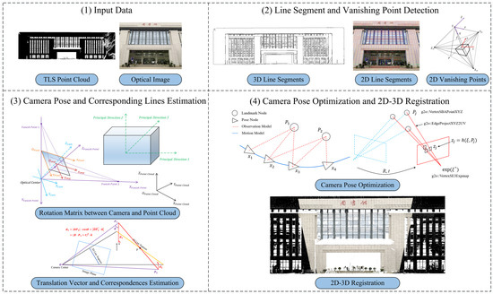
Figure 1.
The overall workflow of proposed automatic 2D-3D registration algorithm VPPnL. (The three Chinese characters depicted on the building facade in the image and point cloud data signify “Library”).
To begin with, we detect 2D and 3D parallel line segment clusters from images and point clouds respectively, along with the coordinates of vanishing points in the pixel coordinate system. Afterwards, due to the basis that the 3D cluster lines are parallel to those lines connecting the camera optical center and corresponding vanishing points [48], we compute the rotation matrix candidates by establishing a vanishing point coordinate system as the link of point cloud principal directions to camera coordinate system. Subsequently, the optimal translation vectors corresponding to each rotation matrix candidate can be calculated by the least squares and the RANSAC algorithm, accounting for the clustering of parallel line segments. Moreover, through the contrast of the number of correspondences obtained by transformation from each pose candidate, we can derive the optimal pose and eliminate line segments without correspondences. Finally, a nonlinear least-squares graph optimization method is carried out to optimize the camera pose and realize the 2D-3D registration and point colorization.
3.1. Line Segment and Vanishing Point Detection
Figure 2 depicts the results of 2D and 3D line segments and vanishing points detection. As for 2D line segment detection, to address the accurate and efficient detection of 2D line segments, we adopt the Line Segment Detector (LSD) algorithm [49], which is computational efficiency and does not require parameter adjustment. The detection result is depicted in Figure 2a. Nevertheless, the weakness of the LSD algorithm lies in the case of when line segments intersect, they will be truncated. Fortunately, the truncation will not affect the direction of line extraction, which can maintain the accuracy of the vanishing point detection and the 2D-3D rotation estimation.
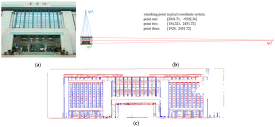
Figure 2.
The results of 3D and 2D line segments and vanishing points detection. (a) 2D line segments detection; (b) 2D vanishing points detection; (c) 3D line segments detection.
With respect to the detection of vanishing points, we exploit an efficient and robust algorithm using 2-line exhaustive searching [50]. After the line segment extraction from LSD, the first vanishing point coordinate is generated by constructing a polar coordinate grid and formulating the 2-line minimal solution set (2-line MSS) hypothesis. Afterwards, the second vanishing point is obtained through exhaustive sampling while the third one is calculated through cross product. The vanishing point detection result is shown in Figure 2b.
Regarding the 3D line segment detection, we select an efficient 3D line detection strategy based on point cloud segmentation and 2D line detection [51]. The pipeline of this algorithm consists of three steps: (i) Region growing and region merging. According to the geometric features (curvature and normal vector) related to the plane properties and the region growing threshold conditions, the point cloud is divided into multiple homogeneous clustering planes. (ii) Plane-based 3D line detection. Using the centroid of the clustered patches as the origin and taking the eigenvectors corresponding to the two largest eigenvalues obtained from the SVD of the fitted plane as the x-axis and y-axis, a local 2D coordinate system is established. The 3D plane is then projected along its normal vector onto this 2D coordinate system. Afterwards, 2D line segments are detected through the LSD algorithm and re-projected to 3D space to derive 3D line segments. (iii) Outlier removal and line merging. Filter the unstructured line segments with local structural information, e.g., parallelism, orthogonality, etc. Subsequently, the line merging process is exploited to merge the 3D line segments that are close together, regularizing the output line segments. Afterwards, we further improve the method by deriving three clusters of line segments using the principal components analysis (PCA) algorithm and removing line segments that did not correspond to the principal direction. As shown in Figure 2c, the 3D lines in the Manhattan scene are grouped into different clusters based on their parallel relationships. This classification of line segments provides constraints for the process of 2D-3D line correspondence, reducing the scope of random sampling, thereby improving both the computational efficiency and the accuracy in identifying corresponding lines.
3.2. Camera Pose and Line Segment Correspondences Estimation
Figure 3 depicts the schematic diagram of rotation between different coordinate systems. Suppose the vanishing point coordinates in pixel coordinate system are . According to the property that the direction from the camera center to the principal point is perpendicular to the image plane, and that the distance from the camera center to the principal point is equal to the focal length, the coordinates of the vanishing points in the camera coordinate system are , where are denoted as camera intrinsic parameters.
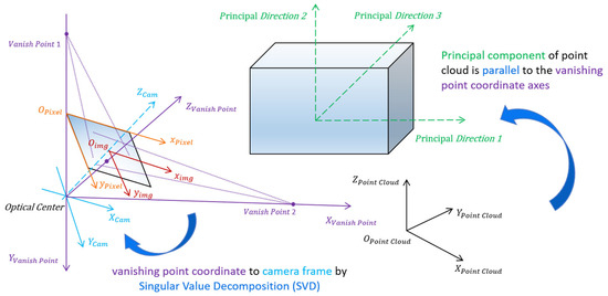
Figure 3.
The schematic diagram of rotation between different coordinate systems.
Due to the fact that the direction from the camera center to the vanishing points corresponding to the three sets of orthogonal lines in space are mutually orthogonal, by calculating the three directional vectors from the camera center S to the vanishing points , a spatial Cartesian coordinate system S-XYZ is formed, which we refer to as the vanishing point coordinate system, as illustrated in Figure 4. Afterwards, the right triangles (which are denoted as ) can be derived. Meanwhile, the image coordinate system is denoted as o-xy, where the direction from camera center S to principal point o is perpendicular to the image plane. The three vanishing points also lie within the image plane. Consequently, an additional set of three right triangles can be obtained. According to the rectangular features in right-angled triangles, some equations can be formulated as follows:
hence, the coordinates of vanishing points in the vanishing point coordinate system can be calculated as , accomplishing the transformation between vanishing point and camera coordinate system.
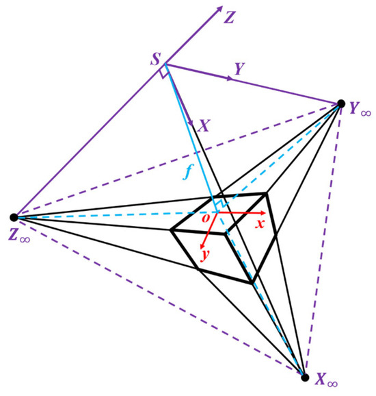
Figure 4.
The schematic diagram of vanishing points in the vanishing point coordinate system.
Meanwhile, the principal directions of point cloud are parallel to the vanishing point coordinate axis directions. However, the direction of a line is bidirectional, leading to two possibilities when rotating one direction to align with a line. Similarly, a 3D coordinate system consisting of three axes possesses possible combinations of arrangements under the condition that each axis corresponds sequentially. For any given axis, such as the x-axis, there are theoretically possible permutations where it could incorrectly correspond to the y-axis or z-axis. However, considering the right-hand rule of the coordinate system, only three permutations are valid. Hence, considering the ambiguity of 3D orientations and the right-hand system criterion, there will be rotation matrix candidates between the principal directions of point cloud and the vanishing point coordinate system. Since building façades in Manhattan world primarily exhibit planar features, the feature intensities in the first two principal component directions are significantly higher than in the third principal direction. Additionally, the clustering orientation of building façades in images predominantly aligns with the two orthogonal principal directions of the fitted façade plane. Therefore, in most 2D-3D registration tasks for Manhattan-style building façades, the number of candidate rotation matrices can be reduced from 24 to 8 by considering only the correspondence of the two dominant directions and excluding the weakest direction evident in both the point cloud and the image.
To identify the rotation from the point cloud coordinate system to the primary directions of the point cloud, the extracted 3D lines are clustered through the k-means algorithm firstly. The average directional vector for each cluster is then calculated, resulting in three principal directions of the target point cloud. The direction vectors of the first two principal directions are rotated to align with the x-axis and y-axis, respectively, allowing for the computation of the rotation matrix from the point cloud coordinate system to the principal directions of the point cloud. Combining the three rotation matrices between different coordinate systems, the rotation matrix from the point cloud coordinate system to the camera coordinate system can be obtained. The flowchart for estimating the rotation matrix candidates is described in Figure 5, and the pseudocode of the rotation matrix candidates’ estimation is summarized in Algorithm 1.
| Algorithm 1: Rotation matrix candidates’ estimation |
| Input: 2D line segments {}, 3D line segments {}, camera intrinsic matrix ; |
Output: 24 rotation matrix candidates
|
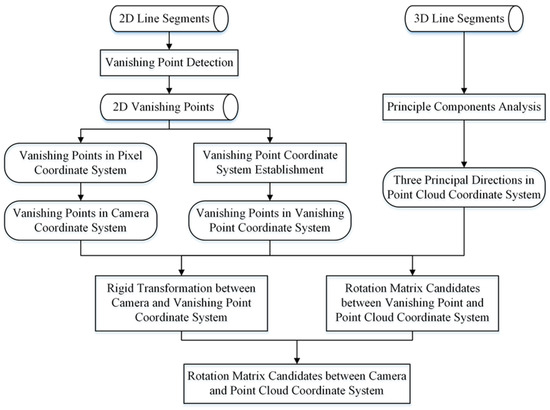
Figure 5.
The flowchart of rotation matrix candidates’ estimation.
To estimate the optimal translation vector from the derived rotation matrix candidates automatically, a traditional method is to use the RANSAC algorithm. This algorithm determines the correct correspondences by randomly selecting sample correspondences during the iterative process, while simultaneously calculating the corresponding pose for each set of correspondences. The transformation result with the largest number of nearest neighbor correspondences is considered as the optimal solution. However, this method includes all features in the sampling process, resulting in a very low probability of obtaining the correct matches, which necessitates a large number of iterations to determine the correct correspondences.
To address the issue of the traditional RANSAC algorithm requiring extensive iterations to achieve correct correspondences, a novel clustering sampling strategy based on the least squares and the RANSAC algorithm is proposed, which takes into account both 2D and 3D line orientations. The strategy is put forward on the basis that the camera optical center, 2D line segment, and the corresponding 3D line segment are located on the same plane [52], and tends to minimize , the distance from the endpoint of the transformed 3D line segment to the plane composed of the camera optical center and the corresponding 2D line segment. As shown in Figure 6, the blue rectangle represents the image plane, within which the blue line corresponds to the 2D line segment feature. The yellow line depicts the 3D line corresponding to the 2D line under accurate pose, theoretically lying on the plane Π formed by the camera center and the 2D line. P1P2 represents the 3D line segments extracted from the point cloud after undergoing estimated pose transformation, with the distances d1 and d2 from the endpoints to the plane Π reflecting the accuracy of the estimation results. The observation equation of the least squares can be established as follows:
where is the normal vector of the plane Π in the camera coordinate system, is the 3D endpoint coordinate in the camera coordinate system, is the 3D endpoint coordinate in the point cloud coordinate system, is the angle between the and vector , and R, t represent the camera pose.
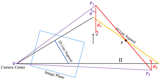
Figure 6.
The schematic diagram of translation vectors determination based on least squares.
Since the 2D-3D correspondences are unknown, the improved RANSAC algorithm is applied, incorporating the clustering of parallel line segments. Specifically, for each candidate R, the corresponding rotation is applied, and the transformed 3D lines are clustered in 2–3 groups of 3D lines (when the scanned data predominantly represent planar structures such as building façades, only the two groups with the most lines are selected). Similarly, when calculating vanishing points in the image, the 2D lines are clustered based on their vanishing points. Samples are then drawn from both the 2D and 3D line clusters to estimate the translation vector t. Compared to the traditional RANSAC algorithm, this method takes into account line orientations and categorizes them into different groups, significantly increasing the probability of selecting the optimal correspondence within the same number of iterations, which greatly improves the computational efficiency and the robustness in automatically identifying 2D-3D correspondences.
After deriving the camera pose candidates, the number of corresponding 2D-3D line segments can be counted. Through the iteration of sampling and the update in the corresponding number, the camera pose possessing the most number of correspondences is regarded as the optimal result among camera pose candidates. Denote the endpoint of 3D line segments in point cloud data as , the normal vector of the plane composed of the camera center and the 2D line segments as . Since the R matrix and the coordinates of are both known, the product between R and can be expressed as :
combine the error equations generated from three 2D-3D correspondences and write in matrix form as shown below:
Combining the K equations in the form of Equation (4) into a matrix formulation yields Equation (5) as follows:
where N is a matrix composed of K sets of normal vectors n, and is a column vector containing the diagonal elements of matrix . Thus, the translation vector t can be calculated according to least squares:
where matrix W is the weight matrix, whose weights are assigned based on the lengths of the 2D lines. With the optimal camera pose, the point cloud data can be transformed into the camera coordinate system, which provides a channel to determine 2D-3D line segment correspondences. The pseudocode of the determination of the translation vector is shown in Algorithm 2.
| Algorithm 2: Optimal translation vector with corresponding rotation matrix determination, and 2D-3D correspondences estimation |
| Input: 2D line segments , 3D line segments , rotation matrix candidates ; |
Output: Optimal translation vector , rotation matrix , correspondences
|
3.3. Camera Pose Optimization and 2D-3D Registration
Unlike the usual PnL algorithms optimizing the camera pose through minimizing the projection error of all correspondences, a novel, efficient, and globally optimal solution for the PnL problem is carried out. Due to the rules of camera imaging, 2D-3D line segment correspondences are located on the same plane. Hence, the proposed strategy aims at minimizing the distance from 3D endpoints of line segments to the plane composed of the camera center and 2D line segments directly, which is defined as in Figure 6. In order to make the camera pose differentiable, the estimated R, t at the former stage are transformed into Lie algebra form . Thus, the distance can be written as follows:
Taking all 2D-3D correspondences into consideration, the minimization function can be described as follows:
where is the number of 3D lines, is the mapping from , and is the exponential map on the special Euclidean group .
To solve the problem of camera pose optimization, a nonlinear least-squares graph optimization strategy is put forward. According to the rough-estimated camera pose R, t along with the intrinsic matrix of the camera, 3D line segments extracted from point cloud can be transformed and projected into the pixel coordinate system. Afterwards, find the similar 2D line segments of each projected line segment concerning the minimal differences between angles and lengths, which are considered as line segments correspondences.
The general graphic optimization (g2o) library [53] is adopted in the process of graph optimization. The rough estimate of the camera pose and the 2D-3D correspondences are imported as the vertexes in the graph, and the set of , the distances from the 3D endpoints of line segments to the plane composed of the camera center and 2D line segments are defined as the edges in the graph. Furthermore, the Levenberg–Marquardt optimization algorithm is employed during the iteration, and the robust Huber kernel is applied to limit the impact of edges with large errors in the final optimization results.
4. Experiments and Results
In this section, we test the proposed algorithm, which is called VPPnL, on synthetic data firstly to verify the feasibility and accuracy of the registration. Subsequently, the VPPnL algorithm is implemented on real data and achieves the colorization of scanned point cloud data from image textures. It is worth noticing that both synthetic data and real data are obtained in scenarios based on the Manhattan hypothesis; i.e., the three principal directions of the data are orthogonal to each other.
4.1. Experiments with Synthetic Data
Considering the difficulty in obtaining 2D images, 3D point clouds, and the actual camera pose simultaneously, this paper employs 3D line data from a public benchmark dataset on multi-sensorial indoor mapping and positioning (MiMAP) [54], as shown in Figure 7a,c,e. The study then simulates camera intrinsic and extrinsic parameters and constructs a camera projection model. The resolution of the virtual camera is pixels, and the focal length is 2000 pixels. The pose of the camera is randomly generated in the world frame. The transformation relationship between the 2D and 3D coordinate system can be formulated as follows:
where fx and fy are set to 2000 pixels representing the focal length, (u0, v0) are set to 960, 500 pixels respectively, representing the coordinate of principal point. The camera pose R, t forms the camera extrinsic matrix. (XWi, YWi, ZWi) denotes the point coordinates in the world (point cloud) coordinate system, (ui, vi) refers to points in pixel coordinate system, and ZC is the scale factor.
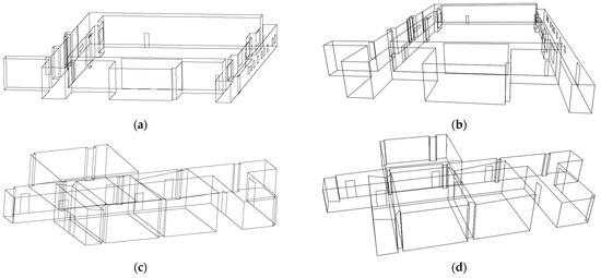
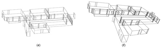
Figure 7.
The 3D/2D lines generated from the MiMAP dataset and the projection model, respectively. (a,c,e) 3D lines from the MiMAP dataset scene1, scene2, scene3, respectively; (b,d,f) 2D lines from the projection model of scene1, scene2, scene3, respectively.
According to Equation (9), the simulated projection model can generate 2D simulated lines of the target object, which is depicted in Figure 7b,d,f.
- A.
- Extraction of 2D and 3D geometric primitives
To achieve cross-modal direct registration between 2D and 3D data, it is first necessary to extract geometric primitive features from the different datasets. This study focuses on the extraction of point and line features for algorithm comparison. The automatic extraction of point primitives employs the SIFT algorithm [25] and Harris 3D algorithm [55] for 2D and 3D point feature extraction, respectively. As for the automatic extraction of line primitives, the strategy involves using the LSD algorithm [49] for 2D line segments and the 3D line extraction algorithm proposed in [51]. The extracted 3D line segments are clustered based on their directional vectors and categorized for storage. After deriving the 2D line segments, the vanishing points detection algorithm proposed in [49] is employed to determine the vanishing point coordinates and cluster the 2D lines. The visualization results of the automatically extracted geometric primitives for the MiMAP dataset scene1 are shown in Figure 8.
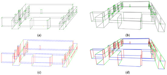
Figure 8.
The visualization results of the automatically extracted geometric primitives for MiMAP dataset scene1. (a) 3D point features detected by Harris 3D; (b) 2D point features detected by SIFT; (c) 3D line extraction with directional vectors based clustering; (d) 2D line extraction and clustering through vanishing point directions. Lines in different colors represent their respective clusters.
By analyzing the geometric primitive features in dataset Scene 1, it can be observed that data in Scene 1 contain 338 line primitives and 214 point primitives in ground truth. Specifically, the automatic point feature extraction method identifies 165 2D points and 148 3D points, accounting for 77.1% and 69.2%, respectively. The automatic line feature extraction method identifies 308 3D lines and 213 2D lines, representing 91.1% and 63%, respectively. It is worth noting that the 2D point feature extraction results contain a significant number of points that do not correspond to actual corner points, with only 64 correct points identified, accounting for 43.2% of the extracted 2D points, which indicates a considerable likelihood of incorrect correspondences when establishing 2D-3D point matches. In contrast, line feature extraction does not suffer from the erroneous extraction of 2D lines. Each 2D line can be accurately matched to a corresponding 3D line, resulting in a more robust extraction process.
- B.
- Establishment of correspondences
After extracting geometric primitive features, a certain number of correspondences must be established to estimate and . The traditional method for finding correspondences involves manual selection, which ensures accurate identification of correct correspondences but requires significant time to complete and incurs high labor costs. The common method for automatically establishing correspondences is RANSAC. However, this approach requires extensive iterations, negatively impacting computational efficiency. The VPPnL algorithm proposed in this study effectively addresses the issue of excessive RANSAC iterations, significantly reducing computation time.
To verify the efficiency and robustness of algorithm VPPnL, comparative experiments are conducted against the traditional RANSAC algorithm. In the experiment, different quantities of 2D and 3D lines, as well as varying outlier rates, are set. The computational time and success rate of correspondence detection for both the VPPnL and RANSAC algorithms are recorded and analyzed. To more accurately reflect the computational efficiency and success rate of the two automated correspondence methods, the experiment was conducted 100 times independently under each set of parameter conditions. As shown in Figure 9, during the process of increasing the number of 2D-3D line pairs from 10 to 80, the VPPnL algorithm consistently maintains a success rate of over 98% in finding correct correspondences. In contrast, the success rate of the RANSAC algorithm shows a significant downward trend, dropping to only 84% when 80 sets of lines are used for correspondence establishment. When it comes to the average computation time per iteration for two algorithms, it is evident that the computational time of the RANSAC algorithm exhibits an approximately exponential increase as the number of line pairs grows. In contrast, the computational time of the VPPnL algorithm remains relatively stable, with the time required to establish correspondences in a single iteration remaining under 2 s even when 80 line pairs are involved in the computation. This demonstrates that in environments with a higher number of line correspondences, the use of the VPPnL algorithm for establishing correspondences is significantly more efficient and robust compared to the RANSAC algorithm.
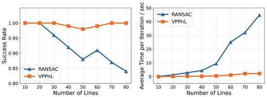
Figure 9.
The success rate and average computation time per iteration of RANSAC and VPPnL for establishing correspondences in a different number of line correspondences.
This study also conducts experiments to evaluate the impact of different proportions of outlier lines on the accuracy and robustness of two algorithms. By progressively replacing 5% to 40% of the lines with incorrect correspondences out of a set of 60 true corresponding lines, the computational time and success rate of both algorithms are compared and analyzed, which are depicted in Figure 10. It can be observed that when the outlier rate exceeds 15%, the success rate of the traditional RANSAC algorithm declines significantly, achieving only a 44% success rate in correct correspondences when the outlier rate reaches 40%. Additionally, as the outlier rate progressively increases, the computational time of the RANSAC algorithm rises sharply. This indicates that the traditional RANSAC algorithm demonstrates limited robustness when dealing with extracted features with high numbers of incorrect correspondences. In contrast, the proposed VPPnL algorithm maintains a success rate exceeding 98% when the outlier rate is below 35% and requires less than 3 s of computation time, demonstrating high robustness and reduced sensitivity to the presence of incorrect correspondences in the extracted features.
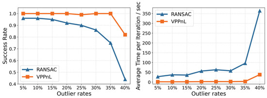
Figure 10.
The success rate and average computation time per iteration of RANSAC and VPPnL for establishing correspondences in different outlier rates of line correspondences.
- C.
- Determination of optimal and
As the strategy described in Section 3.2, the initial estimate of rotation matrix is obtained by relating the principal directions of the point cloud to the camera coordinate system, with the connection facilitated through the vanishing point coordinate system. Subsequently, the initial estimate of the translation vector is determined through cluster-based RANSAC and least-squares optimization. The preliminary results of projecting the 3D point cloud onto the image, using the estimated camera pose and known camera intrinsic parameters, are shown in Figure 11a,c,e. After the process of graph optimization, the optimal camera pose is acquired, and the optimal registration result is shown in Figure 11b,d,f. It is evident that the proposed VPPnL algorithm yields precise registration results in three different scenarios.
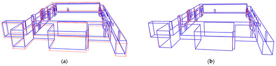
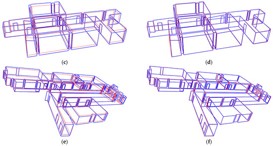
Figure 11.
The 3D/2D lines generated from the MiMAP dataset and projection model, respectively. (a,c,e) Rough projection estimates of scene1, scene2, scene3, respectively; (b,d,f) optimal projection estimates of scene1, scene2, scene3, respectively.
To evaluate the accuracy of the estimated camera pose, the rotation error erot and absolute translation error etrans are denoted as follows:
where and are the j-th columns of the ground truth and estimated rotation matrices and translation vectors, respectively.
To validate the effectiveness of the proposed method, we further conducted a comparative analysis with methods P3P [31], DLT_Points [56], EPnP [33], P3L [57], and DLT_Lines [40]. Considering the insufficient automation of these algorithms in determining matching pairs, feature correspondences are obtained through manual processing, which allows for the computation and comparison of camera pose errors. The quantitative results of the camera pose error are depicted in Figure 12. It can be observed that the VPPnL algorithm has the highest consistency with the ground truth in camera pose estimation and demonstrates robustness across different scenarios, which is probably due to the largest amount of correspondences detected in our strategy. Meanwhile, the comparison between DLT_Point and DLT_Lines reveals that the line-based approach performs better due to the greater robustness and higher repeatability of line primitives across modalities, which further demonstrates the advantages of using vanishing points coupled with 2D-3D lines for registration. Furthermore, the accuracy of EPnP is comparable to that of the VPPnL algorithm, though slightly inferior to ours. This is primarily because the VPPnL algorithm employs orthogonal constraints, effectively suppressing the occurrence of wrong correspondences in complex non-Manhattan structured scenes.
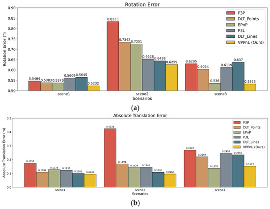
Figure 12.
Camera pose errors with respect to different registration algorithms in three scenarios. (a) Rotation errors ; (b) absolute translation errors .
To evaluate the estimation of camera poses in an intuitive perspective, the distances from the projected lines to the original 2D line segments are calculated. Table 1 presents the distances of 2D-3D registration using the six methods mentioned above. It is noticeable that the VPPnL algorithm achieves the best registration results, with the maximum, mean, and RMSE of the distances between lines being less than 4 pixels, 0.6 pixels, and 1 pixel, respectively. After obtaining the distances between the projected lines and the corresponding 2D lines calculated by six different algorithms, varying distance thresholds are set to evaluate the successful correspondence rates of six algorithms across three scenes. This analysis aims to validate the accuracy and robustness of the proposed VPPnL algorithm. Specifically, as the distance threshold increases incrementally from 0.1 pixels to 3 pixels with a step size of 0.1 pixels, the resulting successful correspondence rate curves for six algorithms across three scenes are depicted, as shown in Figure 13. It is evident that in the experiments for Scene 1 and Scene 2, VPPnL consistently achieved the highest successful correspondence rate across nearly all thresholds. In the experiments for Scene 3, VPPnL exhibited a success rate comparable to that of EPnP. Therefore, the proposed VPPnL algorithm can be applied to practical applications.

Table 1.
Results of competing approaches on synthetic scenes regarding distances from projected lines to 2D line segments in images.
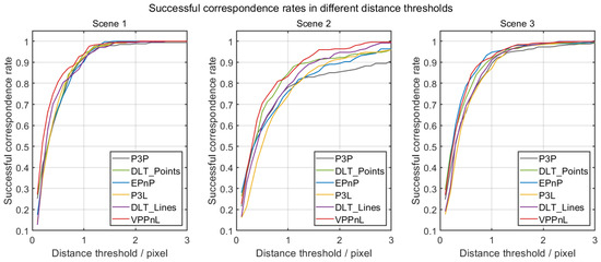
Figure 13.
The successful correspondence rates in different thresholds for six algorithms across three scenes.
4.2. Experiments with Real-World Data
In experiments with real-world data, building upon the publicly available dataset WHU-TLS [58] released by Wuhan University, we further update the scanned point cloud data by autonomously collecting point cloud data for four types of buildings as follows: library, technology building, dormitory, and office building façades. Simultaneously, images of the building façades are captured using a camera to construct a cross-modal registration dataset of point clouds and images. The images of the selected four groups of building façade data are illustrated in Figure 14. The 3D point cloud was obtained using a Leica RTC 360 laser scanner, with a scanning point accuracy of 2.9 mm at 20 m. The 2D images were captured with an iPhone 14 Pro Max camera (Apple Inc., Cupertino, CA, USA), and each image has a resolution of 4032 × 3024 pixels. Prior to image capture, the intrinsic calibration including a lens distortion correction was conducted. The illustrations of the acquisition of 3D point cloud and 2D image data using RTC360 laser scanner and mobile phone are shown in Figure 15.
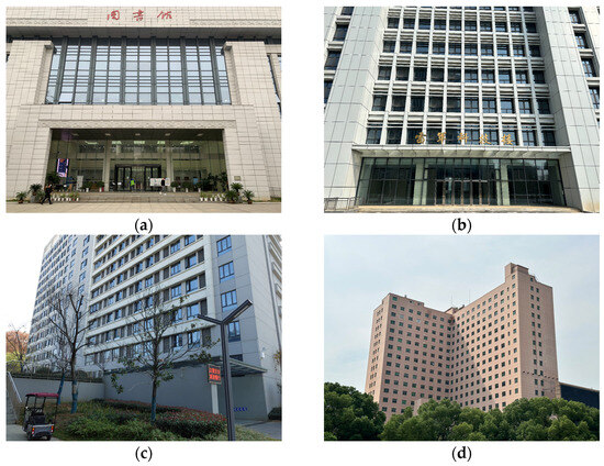
Figure 14.
Images of four groups of building façades: (a) library; (b) technology building; (c) dormitory; (d) office building. (The Chinese characters depicted on the building facade in (a) represent “Library”, while in (b) denote “Lei Jun Technology Building”).
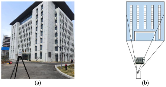
Figure 15.
The illustrations of the acquisition of 3D point cloud and 2D image data. (a) Acquisition of 3D point cloud using RTC360. (b) Acquisition of 2D image using mobile phone.
The qualitative results of the 3D line segments’ projection after 2D-3D registration are shown in Figure 16 for four different scenes. The line segments in blue are 2D lines detected from images, and red line segments are 3D lines from point cloud data. It is evident that the geometric structures of the buildings exhibit a satisfying overall matching result. Meanwhile, it is also apparent that a certain number of line segments still lack correspondences, which is due to the inconsistency in the data collection range of the images and point clouds, as well as the differing line extraction strategies for the two types of data. Line segments from images are primarily extracted based on color and texture differences between adjacent pixels, while line segment extraction in point cloud data considers the spatial geometric relationships between neighboring points.
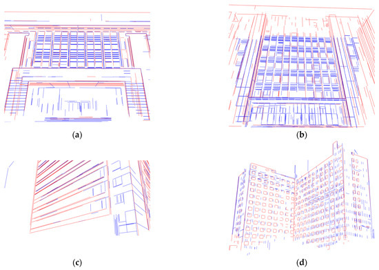
Figure 16.
The 2D and projected 3D line segments after registration (red: projected 3D lines, blue: 2D lines). (a) Library; (b) technology building; (c) dormitory; (d) office building.
To evaluate the registration results quantitatively, several 2D-3D correspondences are selected to calculate the distance between 2D line segments and projected 3D line segments, which are depicted in Figure 17. The results of the maximum, mean, and the RMSE of the distances derived from six different methods are listed in Table 2. It is evident that the proposed VPPnL algorithm achieves optimal results on four sets of real-world data, with the minimal distance between corresponding lines. This superior performance is primarily attributed to the automatic correspondence recognition strategy of the VPPnL algorithm, which identified 98, 45, 45, and 57 correct 2D-3D correspondences in data tests across four different scenarios, significantly surpassing the number of matches achieved by the manual selection method. Additionally, the registration using line primitives outperforms point-based methods, providing additional evidence that line-based registration algorithms exhibit superior robustness, since the data noise and incompleteness in real-world scenarios have minimal impact on their performance. Besides, it should be noticed that the image size in real-world data is pixels, which will result in an increase in the distances between the line segment correspondences.
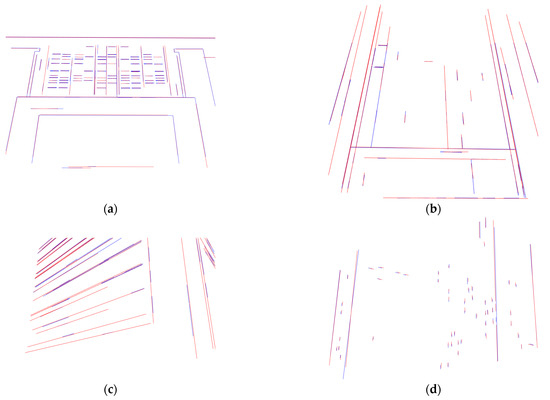
Figure 17.
The 2D-3D line segment correspondences after registration. (a) Library; (b) technology building; (c) dormitory; (d) office building.
Table 2.
Results of distances from projected 3D line segments to 2D line segments in image in real-world data.
Furthermore, after determining the camera pose using the VPPnL algorithm proposed in this paper, the coordinate transformation is utilized to re-project the RGB information of the image points onto the 3D point cloud, achieving point cloud colorization. The visualization results of four different scenes are depicted in Figure 18, where it can be observed that the window frames, window glass, and textures of building surfaces are accurately mapped without visible displacement, further demonstrating the high precision of the proposed registration method.
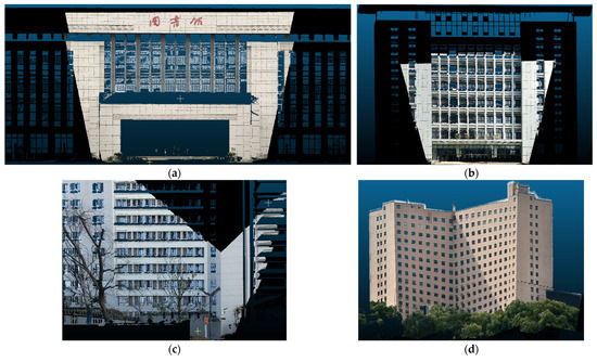
Figure 18.
Colorization of the point clouds through VPPnL algorithm. (a) Library; (b) technology building; (c) dormitory; (d) office building. (The Chinese characters depicted on the building facade in (a) represent “Library”, while in (b) denote “Lei Jun Technology Building”).
5. Discussion and Conclusions
In this paper, we present a novel and automatic solution for 2D-3D registration in Manhattan world based on line primitives. We first extract 2D line segments, 2D vanishing points, and 3D line segments through the LSD algorithm, the 2-line exhaustive searching algorithm and the 3D contour extraction algorithm from point cloud segments, respectively. Subsequently, we derive the rotation matrix candidates by establishing the vanishing point coordinate system as the link of point cloud principal directions to the camera coordinate system. Afterwards, we apply the least squares and the RANSAC, accounting for the clustering of parallel line segments, which is oriented to address the problem of translation vectors estimation and optimization. Furthermore, aiming at minimizing the distance from the 3D endpoints to the plane composed of the camera optical center and 2D line segments, we implement a precise, efficient, and globally optimal solution for the perspective-n-line problem under the nonlinear least-squares graph optimization. Lastly, experiments on synthetic data and real-world data illustrate that our proposed algorithm can address the problem of 2D-3D direct registration in the case of Manhattan scenes where images are limited and sparse.
However, there are limitations in this study which need to be addressed in future work. For instance, the proposed VPPnL algorithm relies on the extraction of the principal direction for implementation, which leads to poor performance in scenarios where there are no significant orthogonal line segments or where vanishing points cannot be generated. Additionally, the present 2D line detection method will detect several line segments that do not exist in the geometric structure due to surface texture differences. These segments cannot be correspondingly identified in point cloud data, resulting in a significant increase in the computation time required to find corresponding lines. Addressing these limitations can generate more robust, high-efficiency, and automatic solutions for 2D-3D data fusion and registration.
Author Contributions
All authors contributed in a substantial way to the manuscript. Conceptualization, J.Z. and Y.H.; methodology, Y.H., R.Z. and L.M.; software, Y.H.; validation, D.Y., Y.Z. and N.W.; data curation, Y.H.; writing—original draft preparation, Y.H.; writing—review and editing, J.Z. and R.Z.; funding acquisition, Y.Z., L.M. and D.Y. All authors have read and agreed to the published version of the manuscript.
Funding
This research was funded by National Natural Science Foundation of China (Grant No. 41871373), Hubei Provincial Natural Science Foundation of China (Grant No. 2024AFB166), and Suqian Sci&Tech Program (Grant No. K202335, K202142).
Data Availability Statement
The data are not publicly available due to privacy.
Conflicts of Interest
The authors declare no conflicts of interest.
References
- Jia, D.; Zhang, W.; Liu, Y. Systematic Approach for Tunnel Deformation Monitoring with Terrestrial Laser Scanning. Remote Sens. 2021, 13, 3519. [Google Scholar] [CrossRef]
- Luo, R.; Zhou, Z.; Chu, X.; Ma, W.; Meng, J. 3D Deformation Monitoring Method for Temporary Structures Based on Multi-Thread LiDAR Point Cloud. Measurement 2022, 200, 111545. [Google Scholar] [CrossRef]
- Hu, D.; Li, Y.; Yang, X.; Liang, X.; Zhang, K.; Liang, X. Experiment and Application of NATM Tunnel Deformation Monitoring Based on 3D Laser Scanning. Struct. Control. Health Monit. 2023, 2023, 3341788. [Google Scholar] [CrossRef]
- He, H.; Ming, Z.; Zhang, J.; Wang, L.; Yang, R.; Chen, T.; Zhou, F. Robust Estimation of Landslide Displacement From Multitemporal UAV Photogrammetry-Derived Point Clouds. IEEE J. Sel. Top. Appl. Earth Obs. Remote Sens. 2024, 17, 6627–6641. [Google Scholar] [CrossRef]
- Gomez, C.; Setiawan, M.A.; Listyaningrum, N.; Wibowo, S.B.; Hadmoko, D.S.; Suryanto, W.; Darmawan, H.; Bradak, B.; Daikai, R.; Sunardi, S.; et al. LiDAR and UAV SfM-MVS of Merapi Volcanic Dome and Crater Rim Change from 2012 to 2014. Remote Sens. 2022, 14, 5193. [Google Scholar] [CrossRef]
- Marmol, U.; Borowiec, N. Analysis and Verification of Building Changes Based on Point Clouds from Different Sources and Time Periods. Remote Sens. 2023, 15, 1414. [Google Scholar] [CrossRef]
- Xue, F.; Lu, W.; Chen, Z.; Webster, C.J. From LiDAR Point Cloud towards Digital Twin City: Clustering City Objects Based on Gestalt Principles. ISPRS J. Photogramm. Remote Sens. 2020, 167, 418–431. [Google Scholar] [CrossRef]
- Li, Y.; Wu, B. Relation-Constrained 3D Reconstruction of Buildings in Metropolitan Areas from Photogrammetric Point Clouds. Remote Sens. 2021, 13, 129. [Google Scholar] [CrossRef]
- Waqas, H.; Jiang, Y.; Shang, J.; Munir, I.; Khan, F.U. An Integrated Approach for 3D Solar Potential Assessment at the City Scale. Remote Sens. 2023, 15, 5616. [Google Scholar] [CrossRef]
- Dong, J.; Zhuang, D.; Huang, Y.; Fu, J. Advances in Multi-Sensor Data Fusion: Algorithms and Applications. Sensors 2009, 9, 7771–7784. [Google Scholar] [CrossRef]
- Khaleghi, B.; Khamis, A.; Karray, F.O.; Razavi, S.N. Multisensor Data Fusion: A Review of the State-of-the-Art. Inf. Fusion 2013, 14, 28–44. [Google Scholar] [CrossRef]
- Xu, J.; Yao, C.; Ma, H.; Qian, C.; Wang, J. Automatic Point Cloud Colorization of Ground-Based LiDAR Data Using Video Imagery without Position and Orientation System. Remote Sens. 2023, 15, 2658. [Google Scholar] [CrossRef]
- Zhang, R.; Li, G.; Li, M.; Wang, L. Fusion of Images and Point Clouds for the Semantic Segmentation of Large-Scale 3D Scenes Based on Deep Learning. ISPRS J. Photogramm. Remote Sens. 2018, 143, 85–96. [Google Scholar] [CrossRef]
- Lin, D.; Jarzabek-Rychard, M.; Tong, X.; Maas, H.-G. Fusion of Thermal Imagery with Point Clouds for Building Façade Thermal Attribute Mapping. ISPRS J. Photogramm. Remote Sens. 2019, 151, 162–175. [Google Scholar] [CrossRef]
- Zhu, J.; Xu, Y.; Ye, Z.; Hoegner, L.; Stilla, U. Fusion of Urban 3D Point Clouds with Thermal Attributes Using MLS Data and TIR Image Sequences. Infrared Phys. Technol. 2021, 113, 103622. [Google Scholar] [CrossRef]
- Castanedo, F. A Review of Data Fusion Techniques. Sci. World J. 2013, 2013, 704504. [Google Scholar] [CrossRef]
- Besl, P.J.; McKay, N.D. Method for Registration of 3-D Shapes. In Proceedings of the Sensor Fusion IV: Control Paradigms and Data Structures, Boston, MA, USA, 30 April 1992; Volume 1611, pp. 586–606. [Google Scholar]
- Segal, A.V.; Haehnel, D.; Thrun, S. Generalized-ICP. In Robotics: Science and Systems; The MIT Press: Cambridge, MA, USA, 2010. [Google Scholar] [CrossRef]
- Yang, J.; Li, H.; Jia, Y. Go-ICP: Solving 3D Registration Efficiently and Globally Optimally. In Proceedings of the IEEE International Conference on Computer Vision (ICCV), Sydney, Australia, 1–8 December 2013; pp. 1457–1464. [Google Scholar]
- Zhao, L.; Zhang, H.; Mbachu, J. Multi-Sensor Data Fusion for 3D Reconstruction of Complex Structures: A Case Study on a Real High Formwork Project. Remote Sens. 2023, 15, 1264. [Google Scholar] [CrossRef]
- Zang, Y.; Yang, B.; Li, J.; Guan, H. An Accurate TLS and UAV Image Point Clouds Registration Method for Deformation Detection of Chaotic Hillside Areas. Remote Sens. 2019, 11, 647. [Google Scholar] [CrossRef]
- Jiang, S.; Ma, Y.; Liu, J.; Li, Q.; Jiang, W.; Guo, B.; Li, L.; Wang, L. Efficient Match Pair Retrieval for Large-Scale UAV Images via Graph Indexed Global Descriptor. IEEE J. Sel. Top. Appl. Earth Obs. Remote Sens. 2023, 16, 9874–9887. [Google Scholar] [CrossRef]
- Tao, W.; Xiao, Y.; Wang, R.; Lu, T.; Xu, S. A Fast Registration Method for Building Point Clouds Obtained by Terrestrial Laser Scanner via 2-D Feature Points. IEEE J. Sel. Top. Appl. Earth Obs. Remote Sens. 2024, 17, 9324–9336. [Google Scholar] [CrossRef]
- Zhu, B.; Ye, Y.; Zhou, L.; Li, Z.; Yin, G. Robust Registration of Aerial Images and LiDAR Data Using Spatial Constraints and Gabor Structural Features. ISPRS J. Photogramm. Remote Sens. 2021, 181, 129–147. [Google Scholar] [CrossRef]
- Brown, M.; Lowe, D.G. Automatic Panoramic Image Stitching Using Invariant Features. Int. J. Comput. Vis. 2007, 74, 59–73. [Google Scholar] [CrossRef]
- Bay, H.; Tuytelaars, T.; Van Gool, L. SURF: Speeded Up Robust Features. In Proceedings of the Computer Vision—European Conference on Computer Vision 2006, Graz, Austria, 7–13 May 2006; Leonardis, A., Bischof, H., Pinz, A., Eds.; Springer: Berlin/Heidelberg, Germany, 2006; pp. 404–417. [Google Scholar]
- Rublee, E.; Rabaud, V.; Konolige, K.; Bradski, G. ORB: An Efficient Alternative to SIFT or SURF. In Proceedings of the 2011 International Conference on Computer Vision, Barcelona, Spain, 6–13 November 2011; pp. 2564–2571. [Google Scholar]
- Harris, C.; Stephens, M. A COMBINED CORNER AND EDGE DETECTOR. In Alvey Vision Conference; Plessey: London, UK, 1988; pp. 23.1–23.6. [Google Scholar] [CrossRef]
- Huang, T.S.; Netravali, A.N. Motion and Structure from Feature Correspondences: A Review. Proc. IEEE 1994, 82, 252–268. [Google Scholar] [CrossRef]
- Fischler, M.A.; Bolles, R.C. Random Sample Consensus: A Paradigm for Model Fitting with Applications to Image Analysis and Automated Cartography. Commun. ACM 1981, 24, 381–395. [Google Scholar] [CrossRef]
- Gao, X.-S.; Hou, X.-R.; Tang, J.; Cheng, H.-F. Complete Solution Classification for the Perspective-Three-Point Problem. IEEE Trans. Pattern Anal. Mach. Intell. 2003, 25, 930–943. [Google Scholar] [CrossRef]
- Persson, M.; Nordberg, K. Lambda Twist: An Accurate Fast Robust Perspective Three Point (P3P) Solver. In Proceedings of the European Conference on Computer Vision (ECCV), Munich, Germany, 8–14 September 2018; pp. 318–332. [Google Scholar]
- Chong, E.K.P.; Zak, S.H. An Introduction to Optimization; John Wiley & Sons, Ltd.: Hoboken, NJ, USA, 2013; ISBN 978-1-118-03334-0. [Google Scholar]
- Lepetit, V.; Moreno-Noguer, F.; Fua, P. EPnP: An Accurate O(n) Solution to the PnP Problem. Int. J. Comput. Vis. 2009, 81, 155–166. [Google Scholar] [CrossRef]
- Li, S.; Xu, C.; Xie, M. A Robust O(n) Solution to the Perspective-n-Point Problem. IEEE Trans. Pattern Anal. Mach. Intell. 2012, 34, 1444–1450. [Google Scholar] [CrossRef]
- Feng, M.; Hu, S.; Ang, M.H.; Lee, G.H. 2D3D-Matchnet: Learning To Match Keypoints Across 2D Image And 3D Point Cloud. In Proceedings of the 2019 International Conference on Robotics and Automation (ICRA), Montreal, QC, Canada, 20–24 May 2019; pp. 4790–4796. [Google Scholar]
- Ren, S.; Zeng, Y.; Hou, J.; Chen, X. CorrI2P: Deep Image-to-Point Cloud Registration via Dense Correspondence. IEEE Trans. Circuits Syst. Video Technol. 2023, 33, 1198–1208. [Google Scholar] [CrossRef]
- Li, J.; Lee, G.H. DeepI2P: Image-to-Point Cloud Registration via Deep Classification. In Proceedings of the IEEE/CVF Conference on Computer Vision and Pattern Recognition (CVPR), Nashville, TN, USA, 20–25 June 2021; pp. 15960–15969. [Google Scholar]
- Hartley, R.; Zisserman, A. Multiple View Geometry in Computer Vision; Cambridge University Press: Cambridge, UK, 2004; ISBN 978-0-521-54051-3. [Google Scholar]
- Xie, Z.; Hu, J.; Peng, D.; Zhu, G. An Accurate Method for Solving the PnL Problem Based on the Reprojection Error. In Proceedings of the 2023 29th International Conference on Mechatronics and Machine Vision in Practice (M2VIP), Queenstown, New Zealand, 21–24 November 2023; pp. 1–6. [Google Scholar]
- Silva, M.; Ferreira, R.; Gaspar, J. Camera Calibration Using a Color-Depth Camera: Points and Lines Based DLT Including Radial Distortion. In Proceedings of the Workshop Color-Depth Camera Fusion in Robotics, Held with IROS, Algarve, Portugal, 7–21 October 2012. [Google Scholar]
- Luxen, M.; Förstner, W. Optimal Camera Orientation from Points and Straight Lines. In Pattern Recognition; Radig, B., Florczyk, S., Eds.; Lecture Notes in Computer Science; Springer: Berlin/Heidelberg, Germany, 2001; Volume 2191, pp. 84–91. ISBN 978-3-540-42596-0. [Google Scholar]
- Zhang, L.; Xu, C.; Lee, K.-M.; Koch, R. Robust and Efficient Pose Estimation from Line Correspondences. In Proceedings of the Computer Vision—Asian Conference on Computer Vision 2012, Daejeon, Republic of Korea, 5–9 November 2012; Lee, K.M., Matsushita, Y., Rehg, J.M., Hu, Z., Eds.; Springer: Berlin/Heidelberg, Germany, 2013; pp. 217–230. [Google Scholar]
- Xu, C.; Zhang, L.; Cheng, L.; Koch, R. Pose Estimation from Line Correspondences: A Complete Analysis and a Series of Solutions. IEEE Trans. Pattern Anal. Mach. Intell. 2017, 39, 1209–1222. [Google Scholar] [CrossRef]
- Yu, Q.; Xu, G.; Cheng, Y. An Efficient and Globally Optimal Method for Camera Pose Estimation Using Line Features. Mach. Vis. Appl. 2020, 31, 48. [Google Scholar] [CrossRef]
- Zhou, L.; Koppel, D.; Kaess, M. A Complete, Accurate and Efficient Solution for the Perspective-N-Line Problem. IEEE Robot. Autom. Lett. 2021, 6, 699–706. [Google Scholar] [CrossRef]
- Yu, Q.; Xu, G.; Wang, Z.; Li, Z. An Efficient and Globally Optimal Solution to Perspective-n-Line Problem. Chin. J. Aeronaut. 2022, 35, 400–407. [Google Scholar] [CrossRef]
- Liu, Y.; Wu, Y.; Wu, M.; Hu, X. Planar Vanishing Points Based Camera Calibration. In Proceedings of the Third International Conference on Image and Graphics (ICIG’04), Hong Kong, China, 18–20 December 2004; pp. 460–463. [Google Scholar]
- Grompone von Gioi, R.; Jakubowicz, J.; Morel, J.-M.; Randall, G. LSD: A Fast Line Segment Detector with a False Detection Control. IEEE Trans. Pattern Anal. Mach. Intell. 2010, 32, 722–732. [Google Scholar] [CrossRef] [PubMed]
- Lu, X.; Yaoy, J.; Li, H.; Liu, Y.; Zhang, X. 2-Line Exhaustive Searching for Real-Time Vanishing Point Estimation in Manhattan World. In Proceedings of the 2017 IEEE Winter Conference on Applications of Computer Vision (WACV), Santa Rosa, CA, USA, 24–31 March 2017; pp. 345–353. [Google Scholar]
- Lu, X.; Liu, Y.; Li, K. Fast 3D Line Segment Detection From Unorganized Point Cloud. arXiv 2019, arXiv:1901.02532. [Google Scholar]
- Brown, M.; Windridge, D.; Guillemaut, J.-Y. Globally Optimal 2D-3D Registration From Points or Lines Without Correspondences. In Proceedings of the IEEE International Conference on Computer Vision (ICCV), Santiago, Chile, 7–13 December 2015; pp. 2111–2119. [Google Scholar]
- Kümmerle, R.; Grisetti, G.; Strasdat, H.; Konolige, K.; Burgard, W. G2o: A General Framework for Graph Optimization. In Proceedings of the 2011 IEEE International Conference on Robotics and Automation, Shanghai, China, 9–13 May 2011; pp. 3607–3613. [Google Scholar]
- Wang, C.; Dai, Y.; Elsheimy, N.; Wen, C.; Retscher, G.; Kang, Z.; Lingua, A. ISPRS BENCHMARK ON MULTISENSORY INDOOR MAPPING AND POSITIONING. ISPRS Ann. Photogramm. Remote Sens. Spat. Inf. Sci. 2020, 5, 117–123. [Google Scholar] [CrossRef]
- Sipiran, I.; Bustos, B. Harris 3D: A Robust Extension of the Harris Operator for Interest Point Detection on 3D Meshes. Vis. Comput. 2011, 27, 963–976. [Google Scholar] [CrossRef]
- Abdel-Aziz, Y.I.; Karara, H.M.; Hauck, M. Direct Linear Transformation from Comparator Coordinates into Object Space Coordinates in Close-Range Photogrammetry. Photogramm. Eng. Remote Sens. 2015, 81, 103–107. [Google Scholar] [CrossRef]
- Dhome, M.; Richetin, M.; Lapreste, J.-T.; Rives, G. Determination of the Attitude of 3D Objects from a Single Perspective View. IEEE Trans. Pattern Anal. Mach. Intell. 1989, 11, 1265–1278. [Google Scholar] [CrossRef]
- Dong, Z.; Liang, F.; Yang, B.; Xu, Y.; Zang, Y.; Li, J.; Wang, Y.; Dai, W.; Fan, H.; Hyyppä, J.; et al. Registration of Large-Scale Terrestrial Laser Scanner Point Clouds: A Review and Benchmark. ISPRS J. Photogramm. Remote Sens. 2020, 163, 327–342. [Google Scholar] [CrossRef]
Disclaimer/Publisher’s Note: The statements, opinions and data contained in all publications are solely those of the individual author(s) and contributor(s) and not of MDPI and/or the editor(s). MDPI and/or the editor(s) disclaim responsibility for any injury to people or property resulting from any ideas, methods, instructions or products referred to in the content. |
© 2024 by the authors. Licensee MDPI, Basel, Switzerland. This article is an open access article distributed under the terms and conditions of the Creative Commons Attribution (CC BY) license (https://creativecommons.org/licenses/by/4.0/).