Abstract
Synthetic aperture radar (SAR) can detect moving targets on the ground/sea, and high-resolution imaging on the ground/sea has critical applications in both military and civilian fields. This paper attempts to use a spaceborne SAR system to detect and image moving targets in the air for the first time. Due to the high velocity of aerial targets, they usually appear as two-dimensional range and azimuth direction defocus in SAR images, and clutter will also have a profound impact on target detection. To solve the above problems, a method of detecting and focusing on a spaceborne SAR target based on a two-dimensional velocity search is proposed by combining the BP algorithm. According to the current environment of the aerial target and the number of system channels, the clutter suppression methods are set and combined with two-dimensional velocity search with different precision, the Shannon entropy under different search velocity groups is used to obtain the search velocity group closest to the actual velocity and realize the integrated processing of moving target detection–focused imaging parameter estimation. Combined with simulation data, the effectiveness of the proposed method is verified.
1. Introduction
As an imaging radar, synthetic aperture radar (SAR) is becoming more and more perfect for target imaging technology. At present, the imaging of stationary targets has been unable to meet the application requirements of SAR in military and civil fields. In modern warfare, moving targets are usually targets with more reconnaissance significance, such as aircraft flying at high velocity in the air, vehicles traveling on the ground, and ships on the sea surface. However, when SAR is used to detect the above targets, the radar echo data are often mixed with land/sea clutter, which needs to be suppressed. Compared with airborne SAR, spaceborne SAR has a more extensive observation range, can obtain higher-resolution images in a larger area, and can obtain global moving target information, which has more important military and civil value. Therefore, using the spaceborne SAR system to effectively monitor moving targets is worthy of further study. At present, the technology of space-borne SAR for ground/sea moving target detection has been effectively applied in the TerraSAR system and the Radarsat2 system [1].
Effective suppression of clutter is required to detect ground moving targets with the help of spaceborne synthetic aperture radar (SAR) systems. Conventional clutter suppression methods can be divided into single-channel and multi-channel processing methods according to the number of channels. Single-channel SAR-GMTI clutter suppression methods mainly include a filtering method, reflection characteristic displacement method, Wiener–Ville distribution method, and so on [2,3]. Limited by the number of channels, the clutter suppression ability of the single-channel correlation method is limited. In practical applications, multi-channel systems are often used to achieve clutter suppression. The traditional multi-channel SAR-GMTI processing schemes mainly include displaced phase center antenna (DPCA), along-track interferometry (ATI) technology, clutter suppression interferometry (CSI) technology, space-time adaptive processing (STAP) technology, etc. Among them, the TerraSAR system uses DPCA technology and ATI technology to realize the detection of moving targets. TerraSAR-X, Tandem-X binary star systems are adopted to enhance the detection performance, and DPCA technology is used for clutter suppression [4]. The Radarsat2 system has two working modes: GMTI and MODEX. Among them, GMTI adopts DPCA technology and ATI technology to realize moving target detection. The MODEX mode uses time-division technology, which can provide up to four channel data, and uses extended DPCA (EDPCA) technology and ISTAP (STAP) technology for moving target detection [5]. In addition, with the development of artificial intelligence technology, researchers have tried to introduce deep learning methods into SAR-GMTI signal processing and proposed corresponding processing schemes, which may also achieve results in more application scenarios in the future [6].
For detecting sea surface targets based on spaceborne SAR, it is often not necessary to suppress sea clutter because of the fine division of sea clutter brought by high resolution. The sea surface moving target detection methods of spaceborne SAR can be divided into traditional and deep learning-based methods. Conventional detection methods are mainly based on the differences in imaging characteristics of SAR images. Among them, the CFAR detection method has been studied by many scholars for its simple principle of high detection efficiency, and strategic improvement methods such as SO-CFAR and GO-CFAR have been formed [7]. Unlike traditional detection algorithms, deep learning-based detection algorithms can automatically learn essential features from a large number of image data, and often have higher accuracy and better robustness in target detection [8,9,10,11].
The above analysis shows that the detection technology of spaceborne SAR for ground/sea surface targets is becoming increasingly mature, and the use of the spaceborne SAR system to detect aerial targets has yet to be reported. A spaceborne SAR system often has the characteristics of comprehensive imaging, which can realize an extensive range of scene imaging, and the aerial target located in the scene will also exist in the echo, so it is feasible to use the spaceborne SAR system to detect the aerial target. The difficulties of high-velocity target detection in spaceborne SAR are as follows: first, it will be affected by high-intensity ground clutter when looking down; second, the blur and defocus caused by the high-velocity movement of the target. Usually, the aerial target is sparse, mainly in the form of a single target and formation target. The formation target can be regarded as a single target because of the consistent motion law. Therefore, based on the research of the spaceborne SAR system under the background of a single aerial target, this paper proposes a novel integrated processing scheme of aerial target detection–focused imaging parameter estimation. The scheme is based on a two-dimensional velocity search combined with the classical radar imaging algorithm, and it realizes the parameter estimation of aerial targets through the focusing results of different search velocities.
2. Spaceborne SAR Aerial Target Detection and Focused Imaging Based on Two-Dimensional Velocity Search
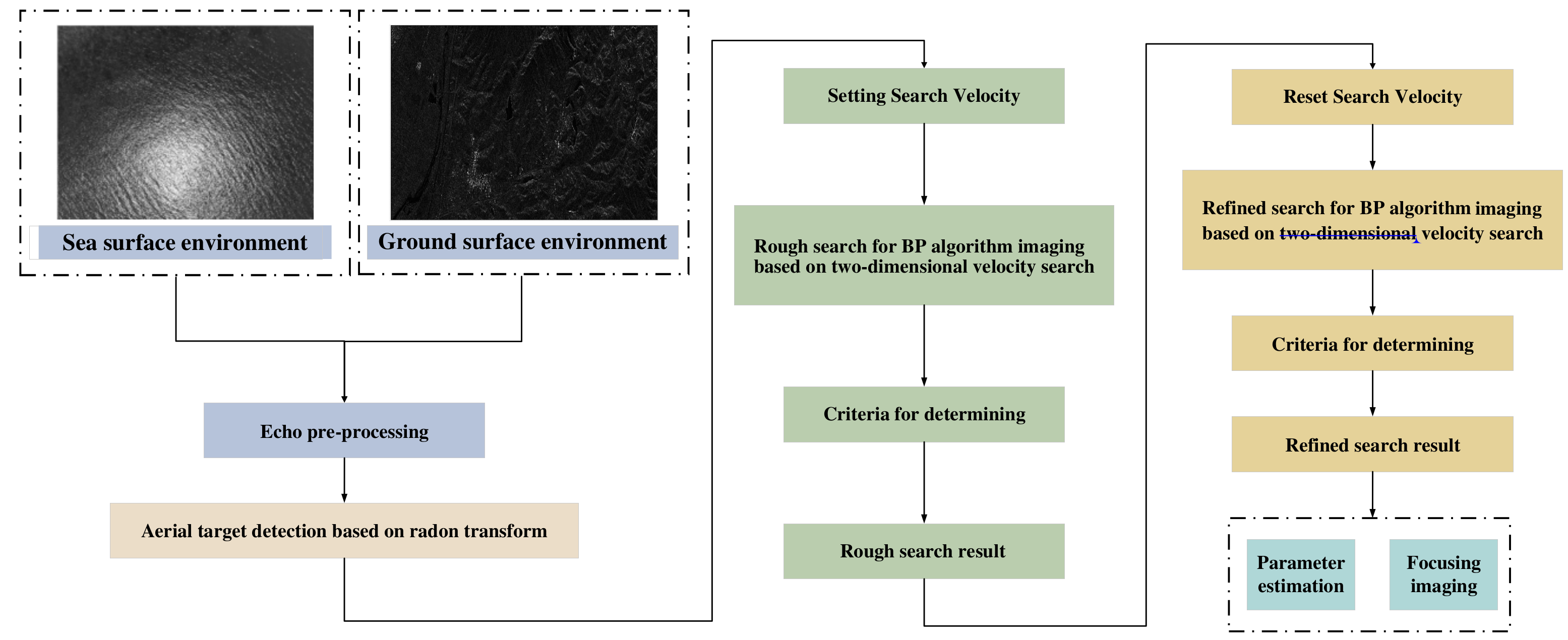
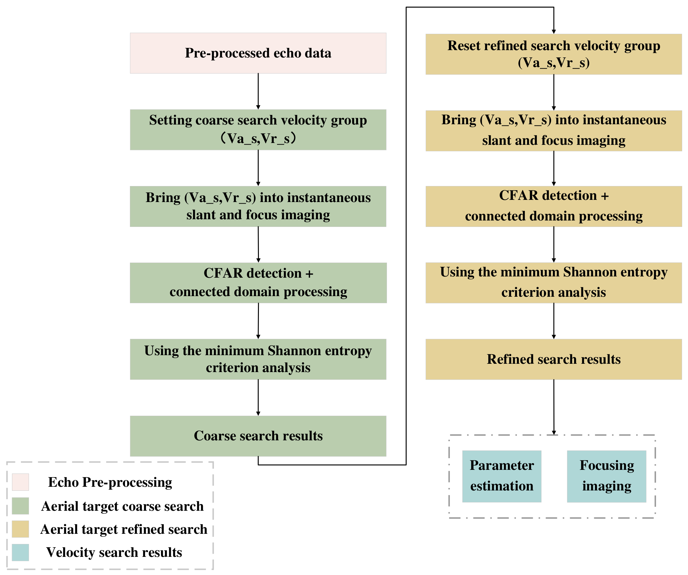
The integrated processing scheme of the aerial target detection–focused imaging parameter estimation based on two-dimensional velocity search is as follows (Figure 1).

Figure 1.
Flow chart of integrated processing scheme of the aerial target detection–focused imaging parameter estimation based on two-dimensional velocity search.
The back projection algorithm (BP algorithm) is a classical algorithm for image processing of time domain echo data, which can accurately construct the target image of the received echo signal in any imaging scene. The imaging algorithm is simple, robust, high-resolution, and suitable for any orbit or flight path model, and the motion compensation is easy. It is especially suitable for double-base and multi-base SAR imaging.
The above processing scheme takes the BP algorithm as the overall framework, combines the two-dimensional velocity search concept, sets a reasonable rough search velocity group, and realizes the focused imaging. The Shannon entropy is calculated for each group of focusing results, and the rough search results are obtained according to the minimum Shannon entropy criterion. Based on the rough search results, the refined search velocity group with higher precision is reset to focus again, and the Shannon entropy is calculated according to the minimum Shannon entropy criterion. The refined search results are obtained by analyzing and comparing them. The refined search results are focused and imaged to realize the integrated processing of the aerial target detection–focused imaging parameter estimation. The Algorithm 1 flow is as follows.
| Algorithm 1: Two-dimensional velocity search-based aerial motion target |
Step 1: Echo preprocessing: range compression + clutter suppression to the ground/range compression to the sea. Step 2: Aerial target detection based on Radon transform: detect and extract the moving target in the preprocessed echo data using the Radon transform; and determine the center position of the target using CFAR detection. Step 3: Rough search of aerial target motion parameters: set a reasonable rough search velocity group to realize the rough search using the BP algorithm. Step 4: Rough locking of aerial target motion parameters: take the minimum Shannon entropy criterion as the index. Step 5: Refined search of aerial target motion parameters: based on the rough search results to narrow the search range and improve the search accuracy, use the BP algorithm to realize the refined search. Step 6: Refined locking of aerial target motion parameters: take the minimum Shannon entropy criterion as the index. Step 7: Output: Output aerial target parameter estimation and focused imaging results. |
2.1. Echo Preprocessing
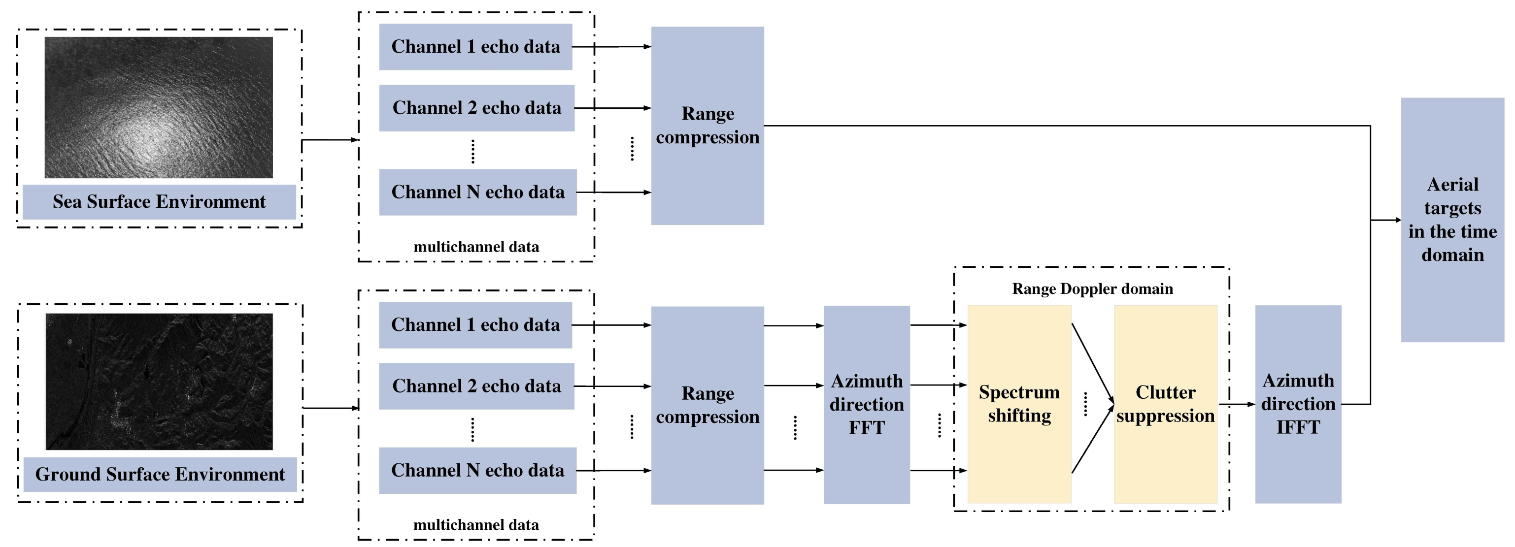
To detect aerial targets effectively, the echoes received by spaceborne SAR need to be preprocessed. When the spaceborne SAR detection background is a land area, it needs to carry out effective ground clutter suppression. Still, it is usually unnecessary to carry out sea clutter suppression when detecting sea areas. Therefore, the echo preprocessing flow chart designed in this scheme is as follows (Figure 2).
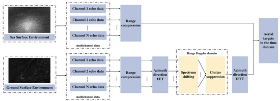
Figure 2.
Flowchart of echo pre-processing.
2.1.1. Echo Preprocessing for Ground Detection
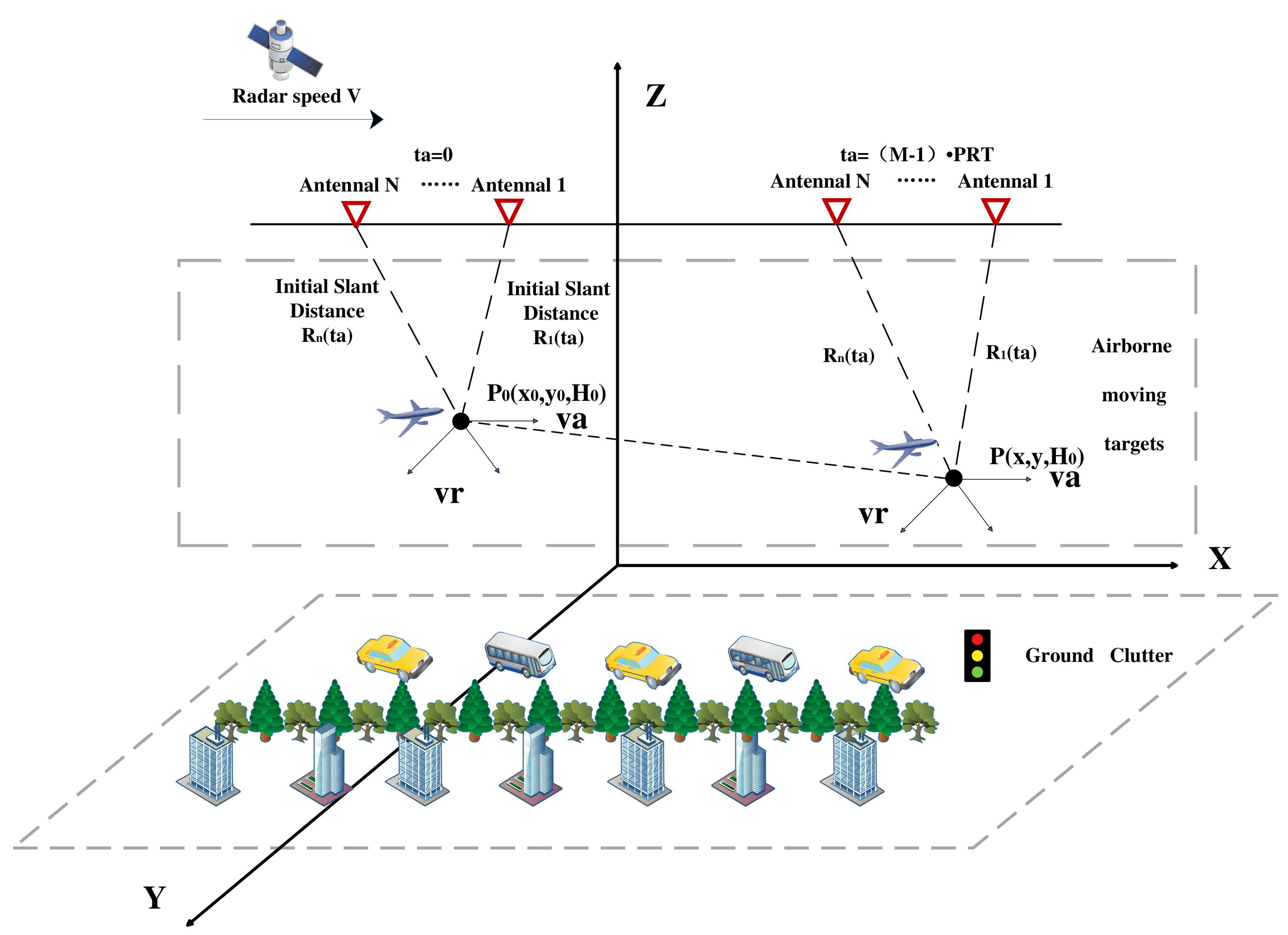
The primary purpose of ground detection echo preprocessing is to suppress the influence of ground clutter on aerial target detection. The geometric configuration of the spaceborne SAR for ground detection is shown as follows [12].
In Figure 3, it is assumed that in a synthetic aperture time, spaceborne SAR transmits M pulses, the total number of receiving channels is N, the pulse repetition time is , the channel spacing is evenly arranged is D, and the antenna adopts the operation mode of one-shot and multiple-receive. The signal is transmitted by channel 1 [13]. The axis perpendicular to the radar track in the horizontal plane is set as the range axis, and the axis parallel to the radar track is set as the azimuth axis. The platform moves from position to position with velocity v. In this synthetic aperture time, the aerial target moves uniformly from point in a straight line to P point, the radial velocity (radar track radial velocity) of the aerial target is , and the tangential velocity (radar track tangential velocity) is , then the instantaneous oblique distance of the channel n of the radar platform can be expressed as
A Taylor expansion of expression (1) and neglecting cubic and higher terms, we obtain
Since spaceborne SAR operates at a long distance and the target velocity is often much smaller than the platform velocity, the instantaneous oblique distance can be simplified as follows:
where , assuming that the transmitted signal is a linear frequency modulation (LFM) signal, the received echo signal can be expressed as follows:
is the range time, is the complex constant, is the azimuth envelope (sinc square window function), is the distance envelope (rectangular window function), is the wavelength, and is the range modulation frequency.
Expression (3) is brought into expression (4) to obtain
The phase of expression (5) is analyzed: the first term is the inherent constant phase of the system, which does not affect the moving target; the second term is the phase shift generated by the velocity information of the moving target; the third term is the interference phase of the moving target, which is related to the number of channels and this term is the key to realizing the detection of moving targets in multi-channel SAR systems; the fourth term is associated with the azimuthal direction, and due to the existence of the target’s radial velocity, an azimuthal positional shift occurs on the image.
Distance compression is applied to the echo signal, and the result is as follows:
Combined with the principle of stationary phase (POSP) [14], the data on each range unit of expression (6) are transformed to the distance Doppler frequency domain by an azimuthal FFT:
is the frequency domain form of the directional pattern of the azimuth antenna. The above expression contains four exponential terms: the first term is the intrinsic phase information of the target; the second is the interference phase information of the moving target; the third and fourth terms are frequency-domain azimuth modulation with linear frequency modulation characteristics.
The following ground clutter suppression processing can be carried out by conventional multi-channel clutter suppression algorithms, such as DPCA, STAP, and so on [15]. In this paper, we take the two-channel spaceborne SAR system for ground detection as an example and carry out the clutter suppression with the help of the DPCA technique [16,17,18]. According to expression (7), the echo signals of channel 1 and channel 2 in the range Doppler domain can be obtained, which are assumed to be and , respectively. is multiplied by the interferometric phase in the range Doppler domain to complete the linear phase compensation to realize the time calibration, and the calibration can eliminate the stationary target; the residual signal is the signal of the moving target, denoted as [19]:
One carries out azimuthal IFFT on , and converts it from the range Doppler domain back to the time domain, and is obtained:
Simplifying expression (11) by taking the modulus value yields:
The above expression contains the sin function term, and expression (12) is also 0 when and k is an integer not equal to 0, that is, . Considering SNR and other practical factors, serious leakage occurs when the radial velocity of an aerial target takes on that value and nearby values [20,21].
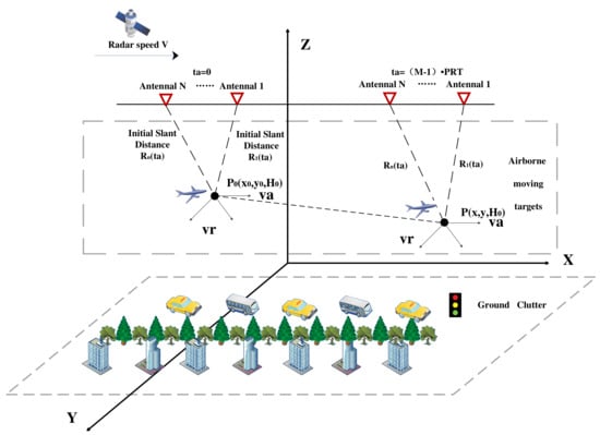
Figure 3.
Geometric configuration of spaceborne SAR for ground detection.
Figure 3.
Geometric configuration of spaceborne SAR for ground detection.
2.1.2. Echo Preprocessing for Sea Detection
The geometric configuration diagram of spaceborne SAR for sea detection is shown as follows (Figure 4).
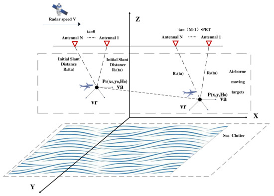
Figure 4.
Geometric configuration of spaceborne SAR for sea detection.
Compared with ground clutter, spaceborne SAR has relatively small sea clutter due to its high-resolution characteristics, and clutter suppression is generally not required. Therefore, the preprocessing of spaceborne SAR echo data is mainly compressed in the range of the echo data.
2.2. Aerial Target Detection Based on Radon Transform
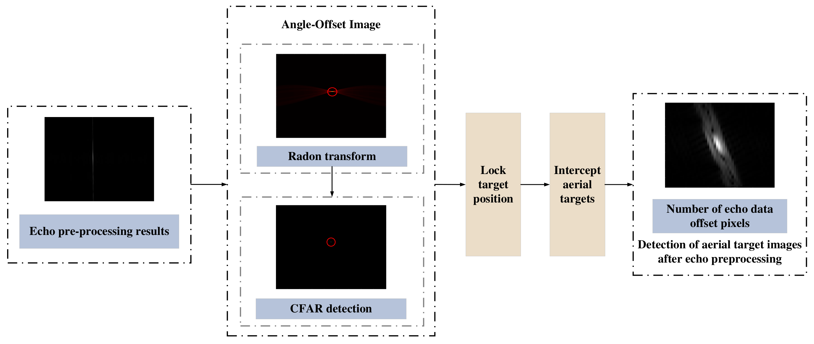
After the preprocessing of the above echo data, the aerial target component with distance compression and clutter suppression is obtained for the ground detection mode, and the aerial target component with distance compression is obtained for sea detection. The aerial target is faster, the phenomenon of cross-range units will be more significant, and it is often approximated as a slanting straight line after distance compression, so the Radon transform can be used to detect the aerial target on the preprocessed echo data. Suppose there is an aerial target in the scene: in that case, its energy will be gathered to a particular pixel or certain pixel points in the image after the Radon transform, and the effective detection of the aerial target can be realized by using CFAR detection and setting a reasonable threshold [22,23]. According to the detection result of the Radon transform, the echo data of the range units where the aerial target is located are intercepted on the preprocessed echo data. At the same time, it can also calculate the number of range units crossed by the aerial target in the observation time, which can be used to estimate the radial velocity initially, narrow the velocity search range, and reduce the calculation amount for the velocity search [24,25,26]. The flowchart is shown as follows (Figure 5).
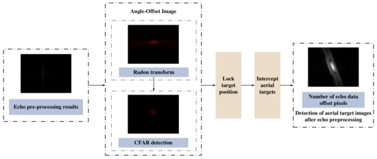
Figure 5.
Flowchart of aerial target detection based on Radon transform.
2.3. Velocity Search
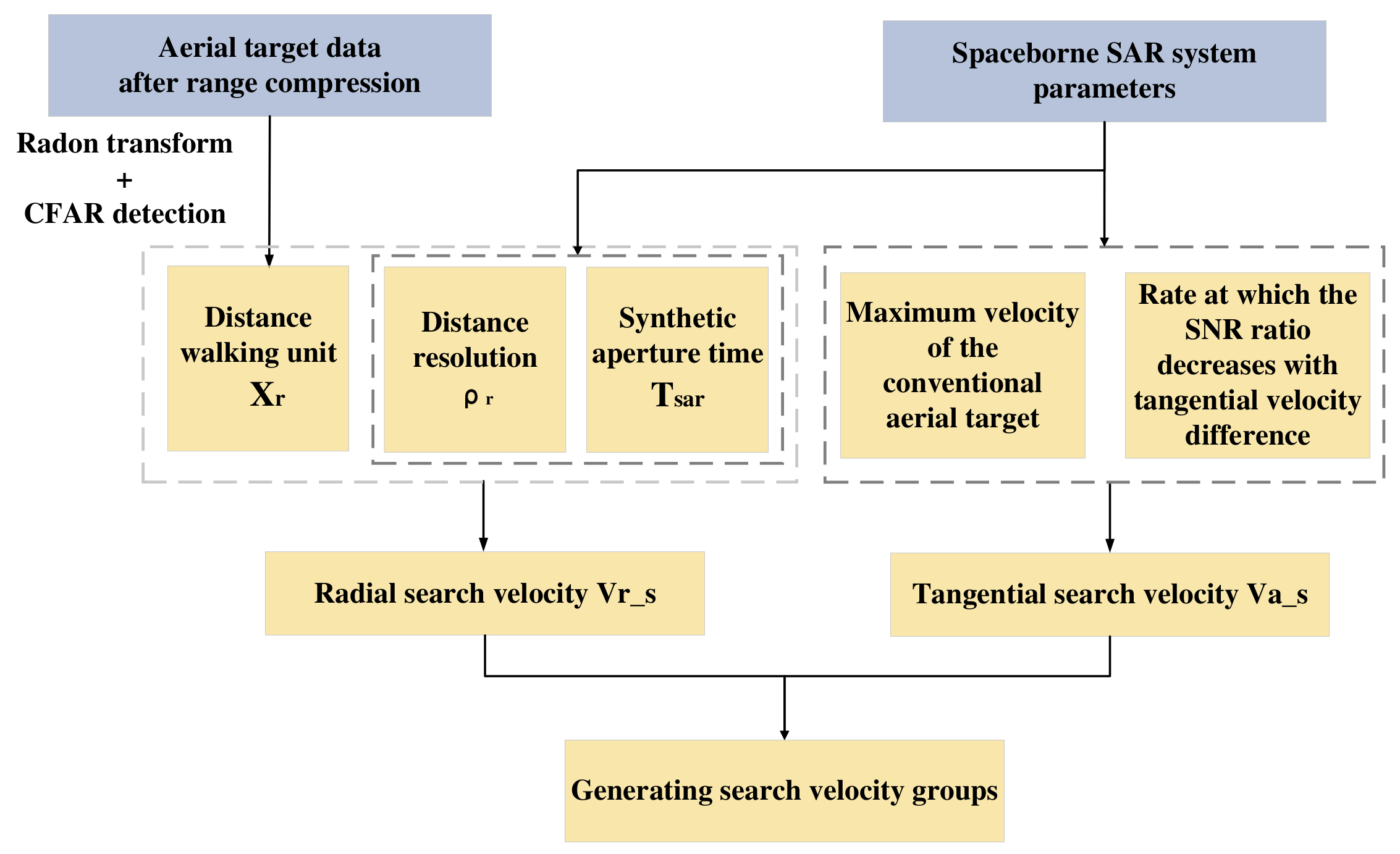
2.3.1. Two-Dimensional Search Velocity Setting
This paper proposes the following scheme to achieve the setting of radial search velocity and tangential search velocity. The distance flow chart is shown in Figure 6.

Figure 6.
Flowchart of two-dimensional search velocity setting scheme.
(1) Radial velocity setting
According to the previous analysis, it can be seen that the radial velocity of the aerial target will bring about a large range walk phenomena, which can be expressed by the following formula:
is the number of pixels in the distance walk of the aerial target, is the distance resolution, and is the synthetic aperture time. Analyzing expression (13), there is an error in calculating the radial velocity by using the distance traveled brought by the high-velocity moving target, and in order to ensure the accuracy of the radial search velocity, a certain margin is set for the radial search velocity:
k is a constant, according to the search environment. In the rough search stage, the estimated radial velocity is taken as the center of the radial search velocity range, the radial rough search velocity range is set from to , and the search range and search interval are set according to the cycle period. In the refined search stage, the rough search results are used as the center of the search scope, and the search interval is reduced to achieve refined search.
(2) Tangential velocity setting
Theoretically speaking, when the searched tangential velocity is inconsistent with the absolute tangential velocity of the aerial target, the aerial target after BP imaging will have a certain degree of defocusing. The more significant difference between the searched value of tangential velocity and the actual value of the aerial target, the more pronounced the defocusing degree of the aerial target. Only when the tangential search velocity is precisely equal to the actual tangential velocity, that is, the difference between the search velocity and the actual tangential velocity is 0 m/s, does the SNR of the aerial target reach the maximum. Therefore, the tangential search velocity interval can be set by referring to the descent degree of SNR of the aerial target. In this paper, the difference between the tangential search velocity and the actual tangential search velocity is set as the tangential search velocity interval in the refined search phase when the SNR of the aerial target decreases by 1 dB compared to its maximum [27].
At the same time, considering the actual situation, this paper assumes that the maximum velocity of the conventional aerial target is about 500 m/s. The range of divergent velocity rough search should include this maximum velocity, and the rough search interval can be set to a larger value to reduce the amount of computation. The range of refined search is set to the same as the search interval of rough search so that no search velocity can be missed during refined search.
2.3.2. Two-Dimensional Velocity Search
After setting the range and interval of the velocity search, two rounds of BP algorithm imaging are carried out with rough search and refined search, and the imaging results of each group of search velocities were analyzed and compared by using the minimum Shannon entropy criterion to achieve parameter estimation and focused imaging of aerial targets [28,29]. The core steps in this process are as follows.
The classical imaging algorithms for radar include the RD algorithm in addition to the BP algorithm used in this paper, which is characterized by high resolution, high robustness, simplicity, and high efficiency. However, the RD algorithm also has certain limitations, for the distance and speed close to the target, there may be a blurring phenomenon, and easy to be affected by strong interference sources. At the same time, the RD algorithm has inherent defects, i.e., the distance unit migration correction needs to be interpolated, which not only increases the computational burden of the algorithm, but also reduces the imaging resolution of the algorithm, and the computational amount of the algorithm increases dramatically with the increase of distance migration. Especially for the strabismic SAR working mode, to achieve high-precision imaging, its imaging quality is significantly reduced. Meanwhile, the BP algorithm is simple, robust, high-resolution, applicable to any orbit or flight trajectory model, has no oblique distance approximation assumption, has easy motion compensation, and especially suitable for dual- and multi-base SAR imaging. Therefore, the BP algorithm is chosen for imaging in this paper.
(1) CFAR detection + connected domain processing
In spaceborne high-resolution SAR images, the aerial target often occupies multiple range units and azimuth units. CFAR detection after the Radon transform has determined the range of radial units where the aerial target is located, and the BP imaging needs to further define the range of divergent units where it is located. Again, CFAR detection is used to pick out the location with a local peak, and then with the help of the idea of the connected domain, the part connected with the local peak is intercepted and identified as the pixels occupied by the aerial target. The rest is considered to be the clutter component or noise component, without further analysis [30].
The image connected domain refers to the connected region of adjacent pixels with the same pixel value (usually black or white) in an image. An image can contain multiple different connected domains, each of which can be represented as an independent object or region. In image processing, through the connected domain analysis of the image, object detection, target tracking, image segmentation, and other operations can be carried out.
(2) Minimum Shannon entropy criterion
Theoretically, the closer the velocity combination in the search velocity group is to the absolute two-dimensional velocity of the aerial target, the better the focusing effect of the aerial target after BP imaging. The focusing effect of BP imaging can be used to determine the velocity parameters of the aerial target, and it is necessary to select indicators to judge the focusing effect of the aerial target. The high-speed movement of the aerial target does not change the total energy of the signal; it will change the transverse energy distribution of the original image, that is, the defocusing phenomenon. Therefore, various image evaluation functions are intuitively used to measure the degree of convergence and dispersion of image energy. In this paper, the minimum Shannon entropy criterion, which is included in the entropy function class of conventional image evaluation function, is selected. Since aerial targets often occupy multiple pixels in high-resolution SAR images, these pixels will affect each other in the focused imaging process (for example, the superposition effect of the main lobe and side lobe). Therefore, it is not reasonable to choose a single peak or average value as an indicator, and a relatively robust indicator that can comprehensively consider the above situations should be selected. The minimum Shannon entropy criterion is more universal, and the result is more accurate. Shannon entropy is an important concept in information theory, proposed by Claude Shannon in 1948, to measure the uncertainty or amount of information in a system. Shannon entropy is often used to describe the degree of uncertainty of a random variable, and can also be used to measure the average information content of an information source. The lower the Shannon entropy, the more stable the system or the image. In this paper, the content to be evaluated is SAR images under different search speed groups, and the Shannon entropy of the current image is calculated and stored according to the order of distance and orientation in different search speed groups. The image is drawn according to the calculated Shannon entropy, and the search speed group with the lowest Shannon entropy is selected as the search result [31,32].
p and q are the number of pixels in the range direction and azimuth direction of the aerial target after focusing, respectively, and is the results of spaceborne SAR focused imaging using the BP algorithm for different groups of search velocities . According to the minimum Shannon entropy criterion, when the minimum value of expression (15) is obtained, the corresponding two-dimensional velocity is considered the actual velocity of the aerial target. The specific flow chart of two-dimensional velocity search is as follows (Figure 7).
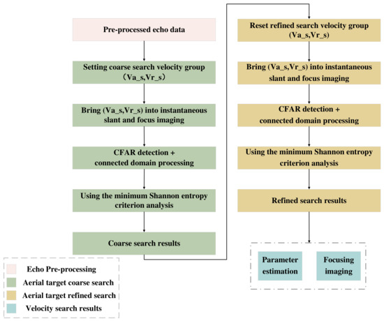
Figure 7.
Flowchart of two-dimensional velocity search based on BP algorithm.
3. Simulation Results and Analysis
3.1. Parameter and Echo Simulation
The effectiveness of the above method is verified through simulation experiments. This part uses Matlab 2021a simulation software to simulate. To conduct a simulation experiment, we will take two-channel spaceborne SAR ground detection as an example to conduct a simulation experiment. The radar system transmits linear frequency modulation signals. The specific radar system parameters and aerial target motion parameters are set as follows (Table 1) [33,34,35].

Table 1.
Parameter setting table related to simulation experiments.
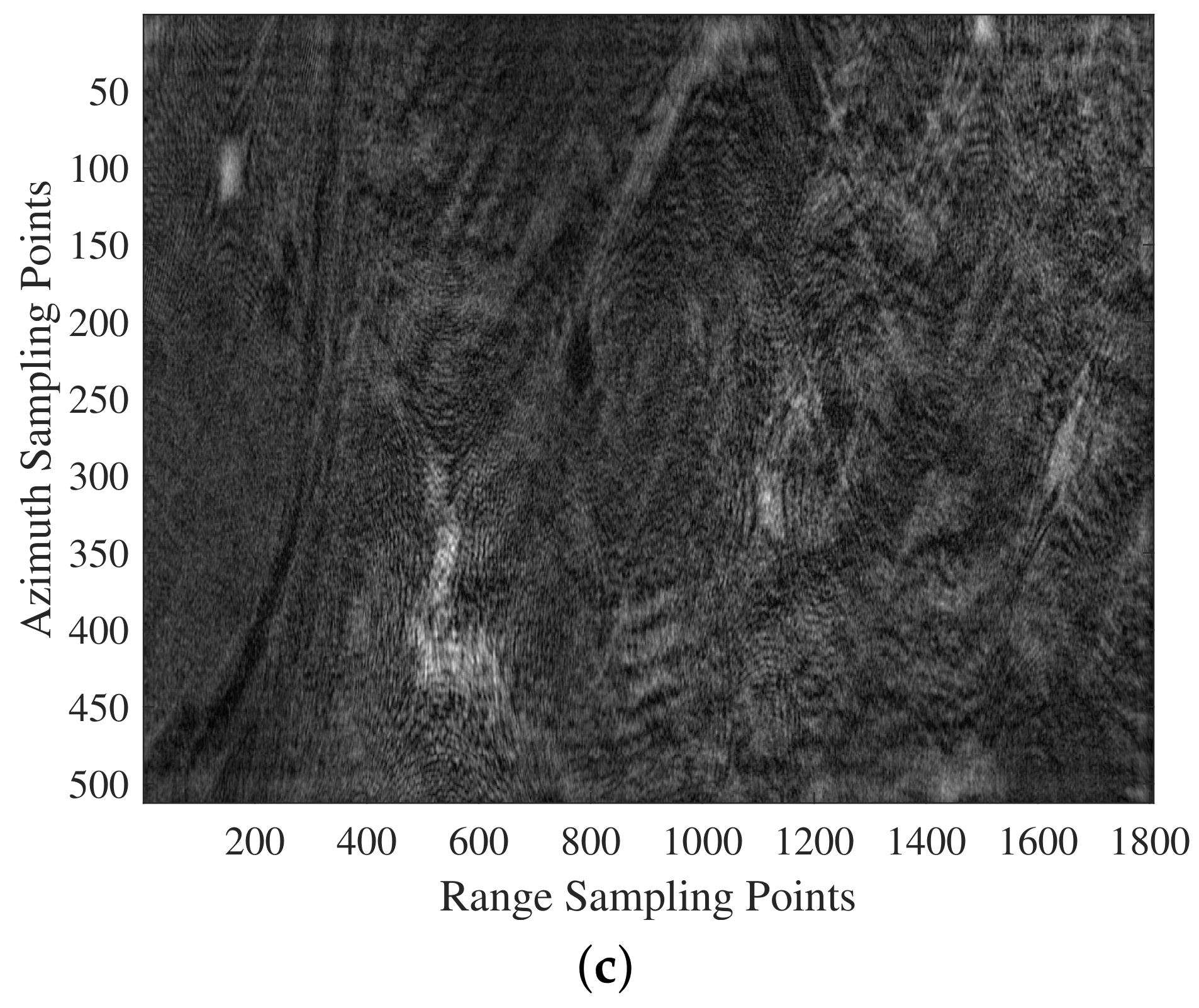
In the experiment, the result of the measured SAR image of a region by Gaofen-3 is selected as the background clutter for echo simulation. In the above echo, the simulated aerial target and noise are added by simulation, assuming that the aerial target occupies 26 pixels and each pixel point has the same amplitude. The aerial target configuration is shown in Figure 8a. Due to the selection of the azimuthal slow time variable, the target is located in the center position within the imaging area, and the measured SAR image of a region with an aerial target is shown in Figure 8b, and the simulation result of the scene echo is shown in Figure 8c. The background clutter and the aerial target cannot be distinguished from the simulated echo in Figure 8c, and further echo processing is required.
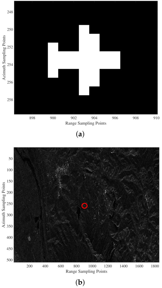

Figure 8.
Echo simulation. (a) Aerial target configuration. (b) Measured SAR images of a region. (c) Scene echo simulation results with aerial targets.
3.2. Spaceborne SAR Aerial Target Detection and Focused Imaging Based on Two-Dimensional Velocity Search
(1) Search velocity settings
Under the current radar parameters, let , and combine with expression (14), the margin is calculated to be 38.52 m/s. Considering various factors such as the amount of computation, the rough search radial search velocity range is set to 80 m/s, the search interval is set to 20 m/s, and the search range center is set according to expression (11). The results of the rough search are set to the search center of the refined search, and the search interval is halved to 10 m/s and the search range is halved to 40 m/s simultaneously.
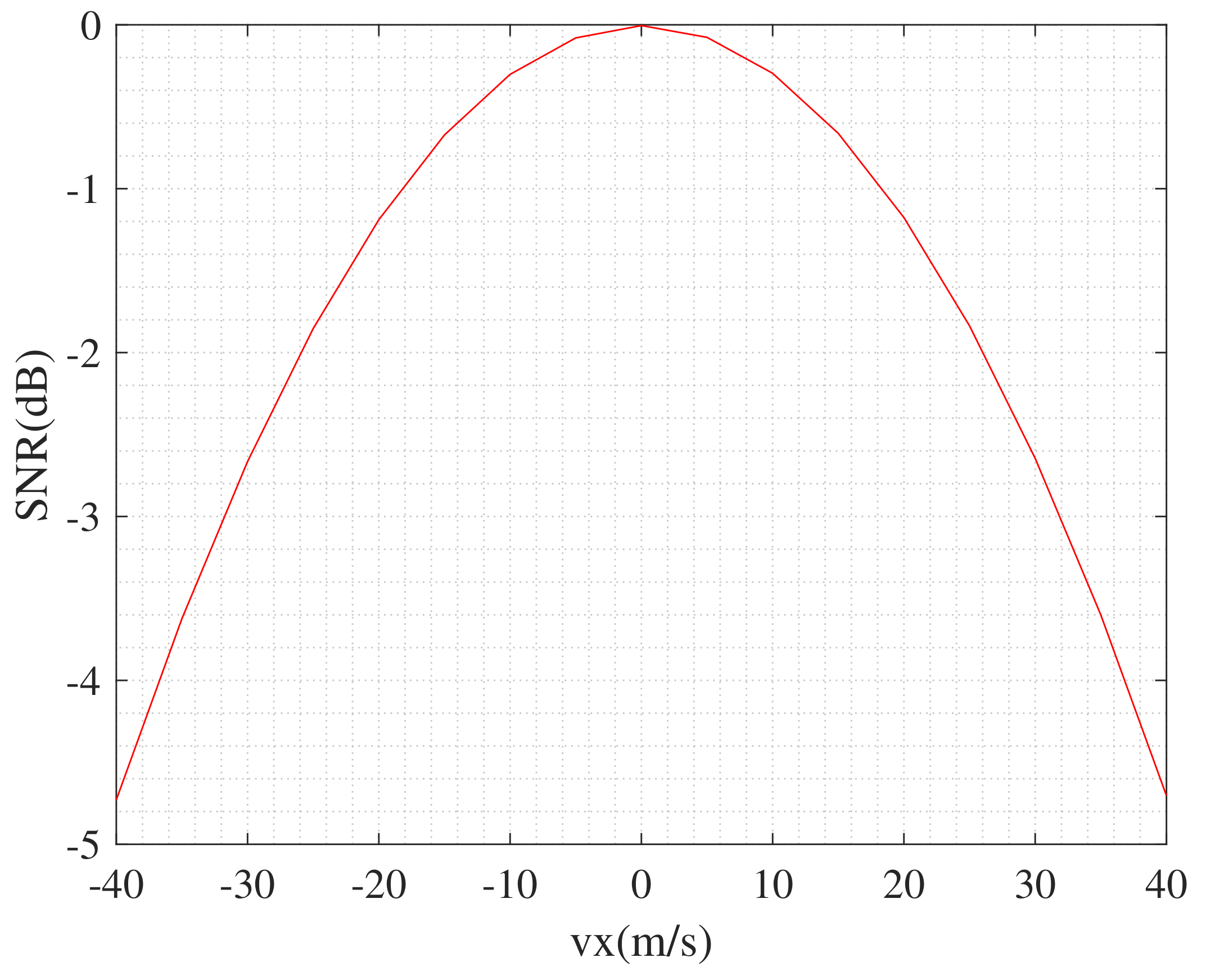
The maximum velocity of conventional aerial targets is about 500 m/s, so the range of rough search tangential velocity is set to 0–640 m/s, and the interval is 80 m/s. The following figure shows the change in signal-to-noise ratio (SNR) at the different tangential search velocity. When the tangential search velocity is precisely equal to the actual tangential motion velocity of 286 m/s, the SNR is maximum; the larger the difference between the tangential search velocity and the actual tangential motion velocity, the smaller the SNR.
Figure 9 is analyzed, where there is a difference between tangential search velocity and actual tangential velocity, that is, the difference between tangential search velocity and actual tangential velocity. For the current radar system, SNR reaches the maximum when the tangential search velocity is gradually away from the actual tangential velocity. When SNR drops 1 dB, and the tangential velocity interval is close to 20 m/s. Therefore, the divergent search velocity interval can be set by referring to 20 m/s. The tangential velocity search range of refined search is set to the same as the search interval of rough search, that is, 80 m/s, to ensure no missing search velocity.
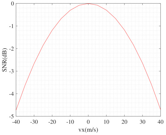
Figure 9.
Tangential search velocity performance curve under the current parameters.
(2) Aerial target detection, parameter estimation, and focused imaging
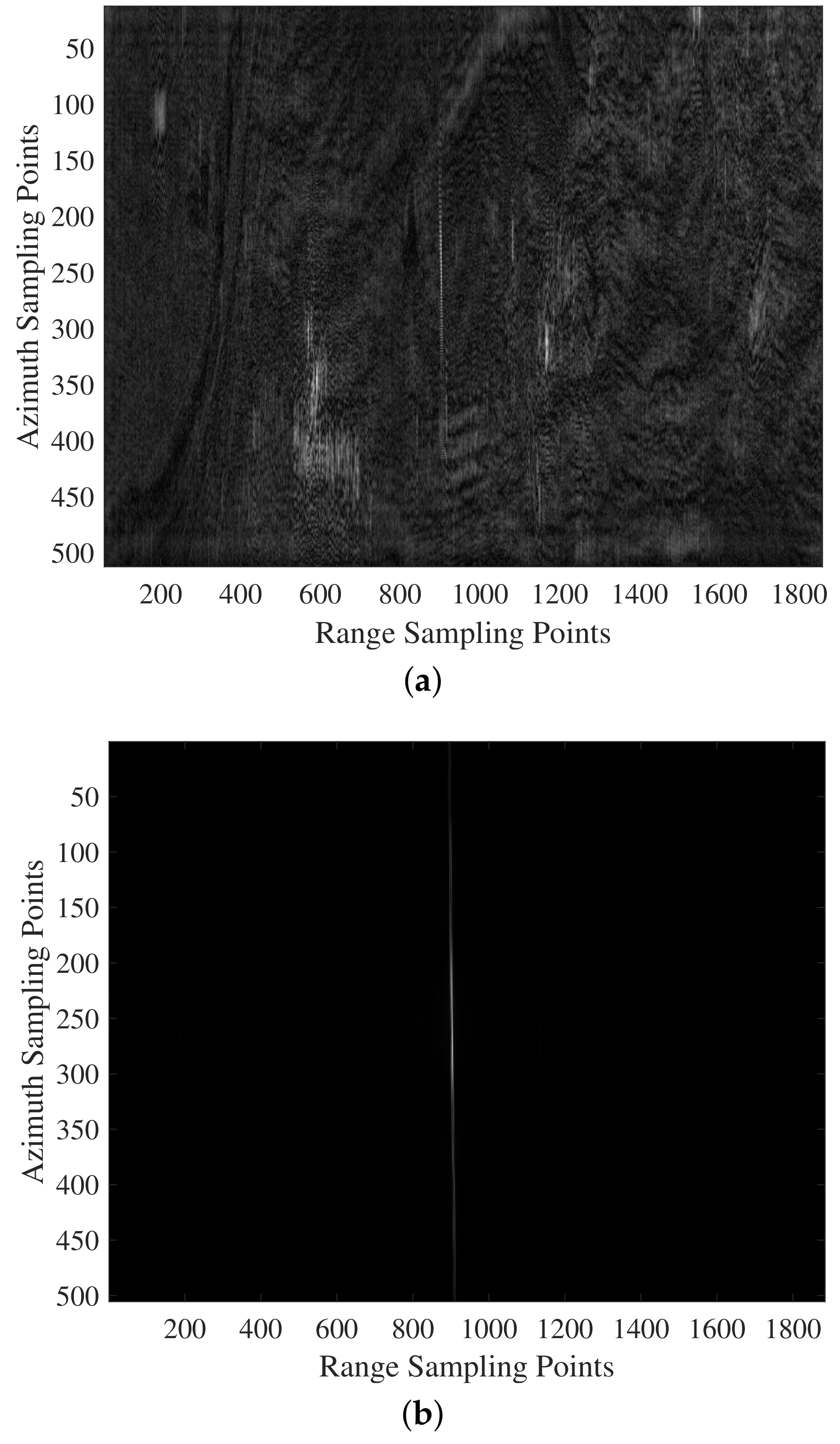
The distance compression is performed on the simulated scene echo signal, and the result is shown in Figure 10a. Then, the echo data are converted from the time domain to the range Doppler domain for clutter suppression to complete the echo preprocessing process. Since the simulation is two-channel echo data, the range Doppler domain DPCA algorithm is used here to realize the clutter suppression. The processed image is shown in Figure 10b. From Figure 10, it can be seen that the background clutter is effectively suppressed.

Figure 10.
Range compressed image. (a) Without clutter suppression. (b) After clutter suppression.
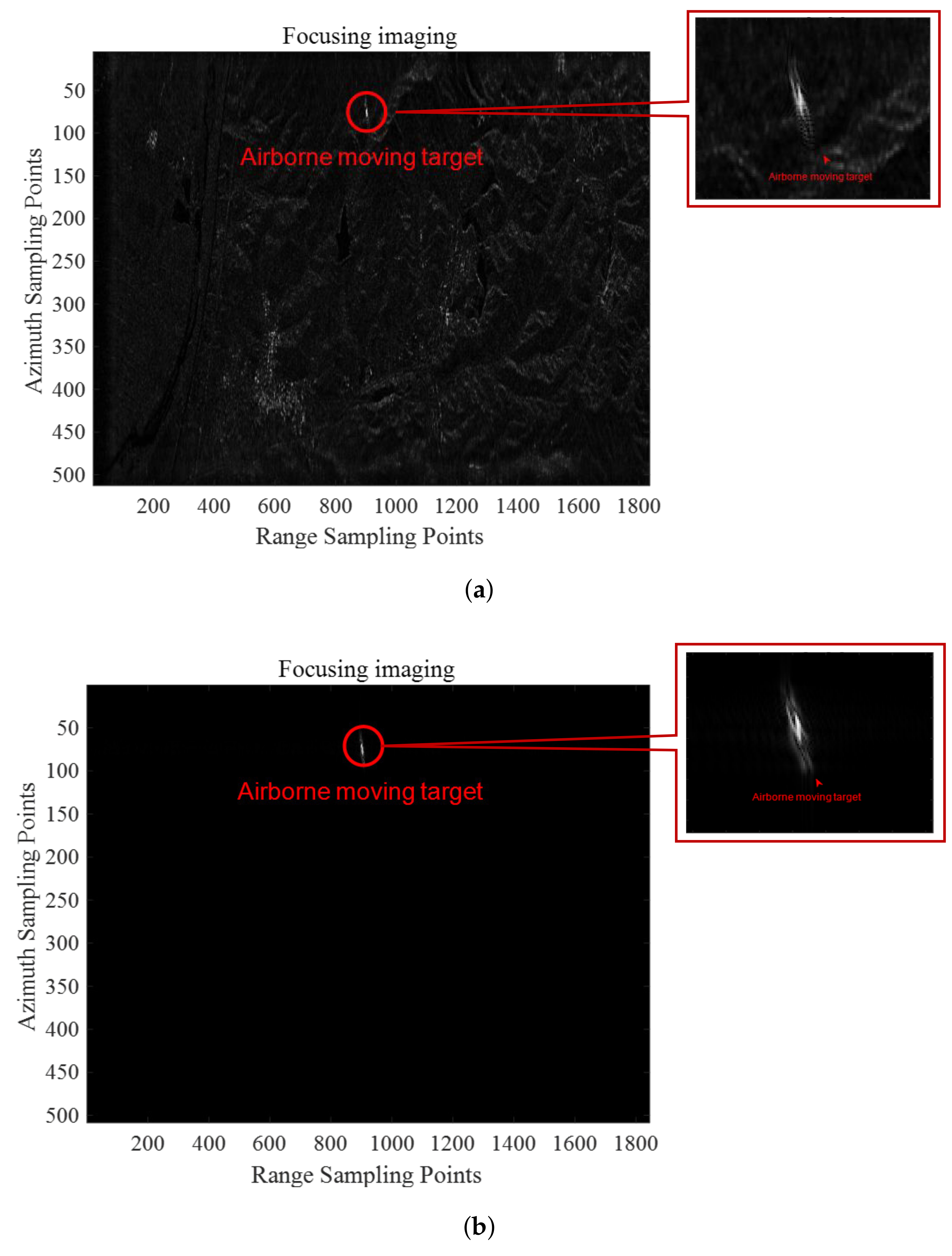
Suppose the simulated scene echo is processed according to the stationary target the BP algorithm. In that case, the presence of the aerial target’s two-dimensional velocity leads to severe scattering phenomenon, as shown in Figure 11a. Due to divergent velocity, the azimuthal linear modulation frequency of the aerial target differs from that of the stationary target, resulting in azimuthal defocusing of the aerial target. Due to radial velocity, the aerial target will have a severe phenomenon of moving across the range units, resulting in distance defocus. In addition, the radial velocity of the aerial target will also bring about the azimuthal shift after imaging, and the degree of the change is proportional to the radial velocity of the aerial target. The clutter suppression process does not affect the defocusing of aerial targets, as shown in Figure 11b. The defocusing phenomenon of the aerial target will cause its energy dispersion, which seriously impacts detection.
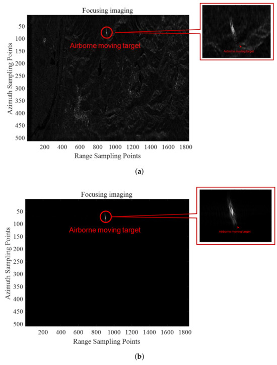
Figure 11.
The results of processing the scene echo according to the stationary target BP algorithm. (a) Focused imaging results before clutter suppression. (b) Focused imaging results after clutter suppression.
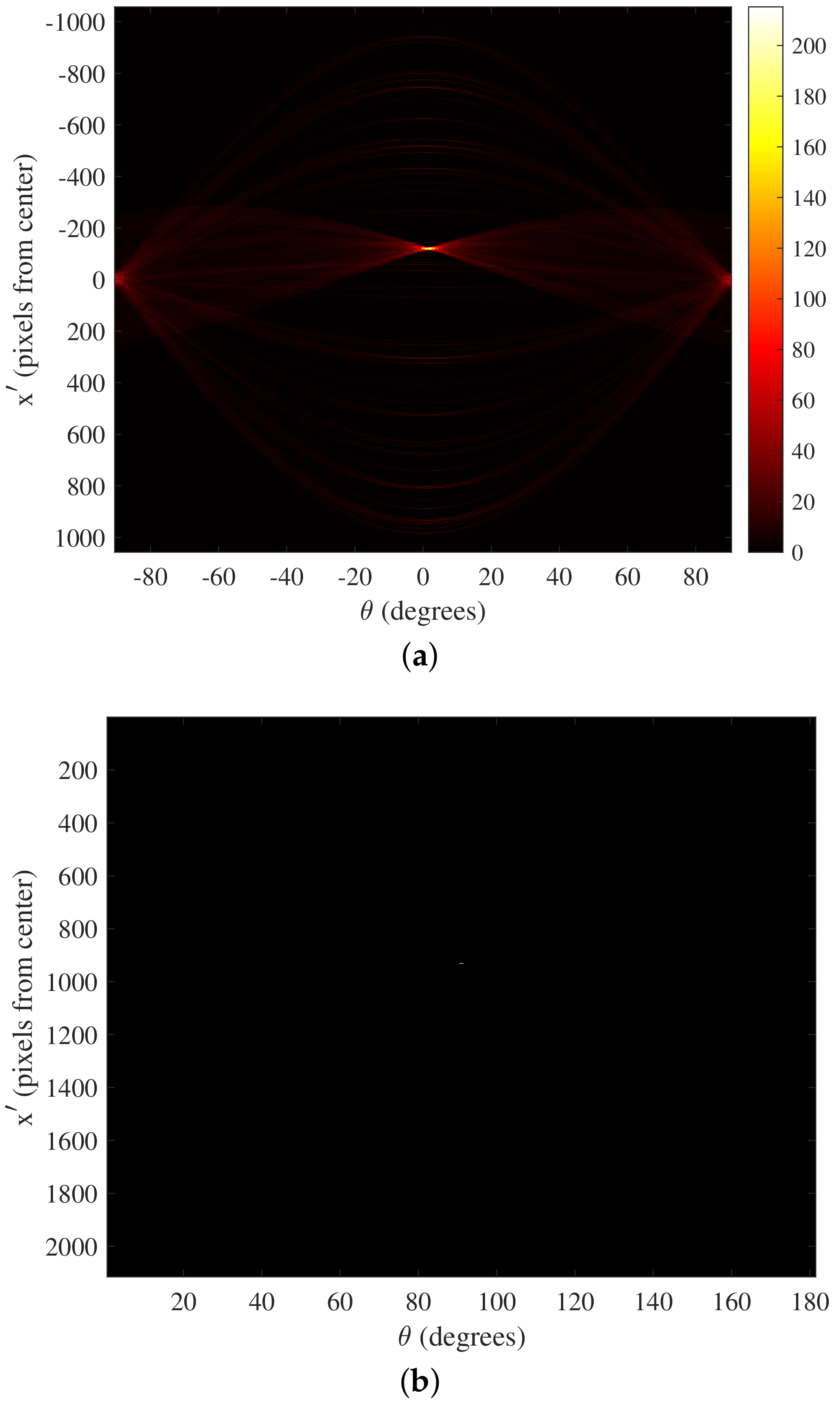
The Radon transform is applied to the result of the echo data preprocessing, as shown in Figure 12a. From the figure, it can be seen that the horizontal axis is the detection angle, and the vertical axis is the offset between the distance image position where the aerial target is located and the center of the distance image in the search range, which is less than 0 for the left offset and greater than 0 for the right offset.
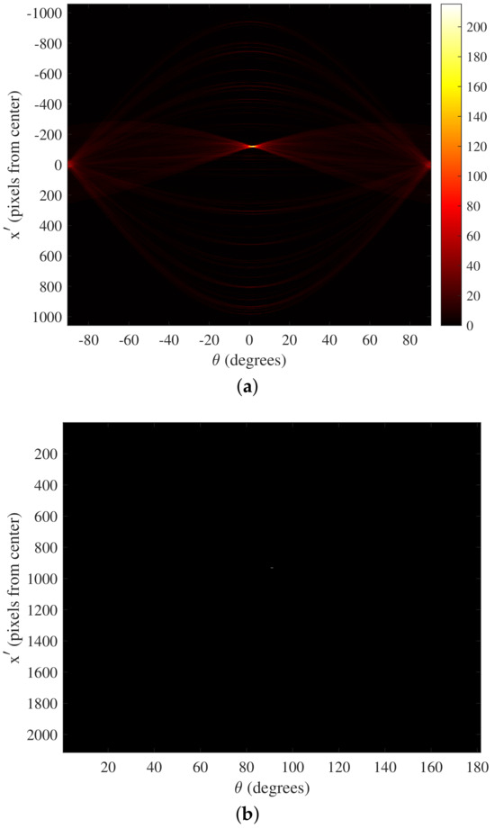

Figure 12.
Determine the search range and target center location. (a) Radon transform results. (b) CFAR detection acquires the target center location. (c) Capture the target image.
The image after the Radon transform is processed with CFAR detection to achieve aerial target detection and center position determination, as shown in Figure 12b. From the figure, it can be seen that an aerial target is included in the image domain after the Radon transform, and based on the position of the target in the image domain after Radon transform, the range of range units where the aerial target can be determined.
Then, the echo data within the range of this range unit are intercepted, as shown in Figure 12c. Subsequent velocity searches are processed for the intercepted echo data, which can effectively reduce the amount of signal processing operations. At the same time, the approximate radial velocity of the target can be calculated by estimating the number of range units that the target has passed across. Figure 12c shows that the aerial target has crossed about 17 range units, and the estimated radial velocity is 328 m/s.
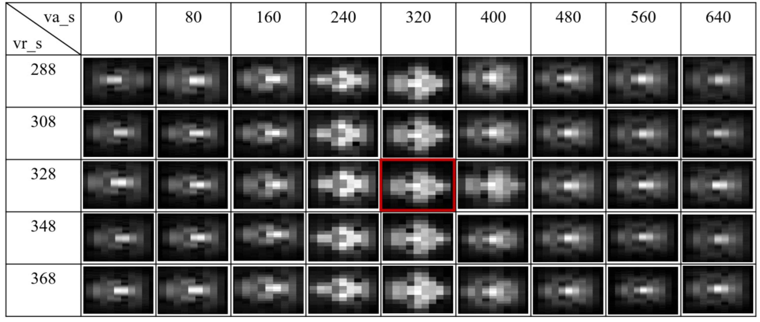
The intercepted echo data containing aerial targets are processed for velocity search. First, the rough search is carried out. Combined with the radial velocity estimated above, the radial search velocity ranges from 288 m/s to 368 m/s, and the search velocity interval is 20 m/s. The tangential search velocity ranges from 0 m/s to 640 m/s, and the search velocity interval is 80 m/s. A rough search is conducted with the above two-dimensional search velocity parameter set, and the results are shown in Figure 13.
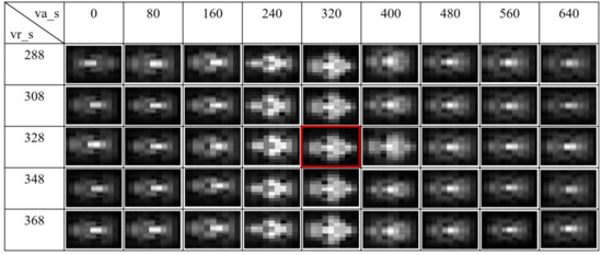
Figure 13.
Focused target imaging for different rough search velocity groups.
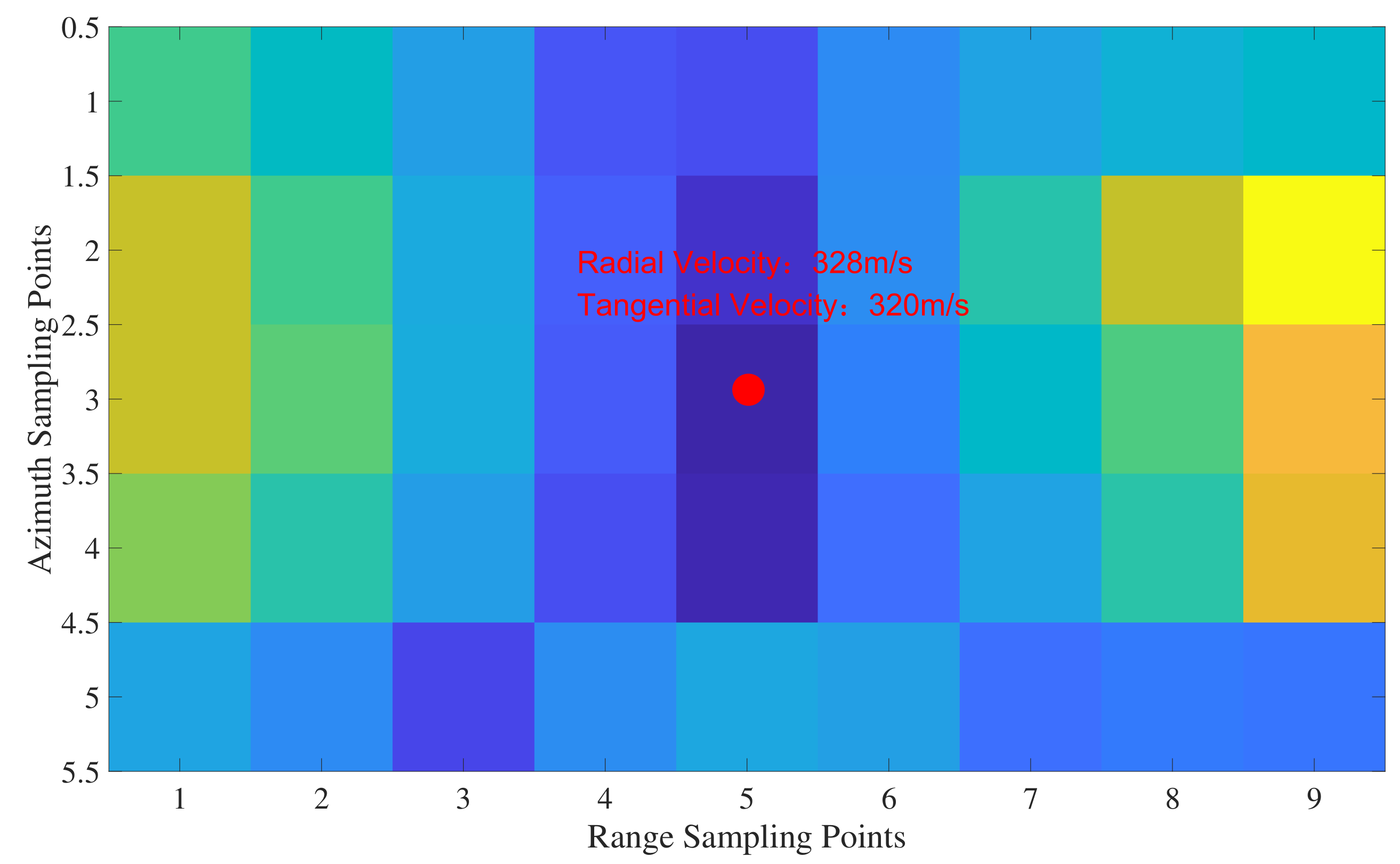
Its corresponding Shannon entropy is calculated for the aerial target focusing imaging results under different rough search velocity groups and stored sequentially according to the search velocity groups, as shown in Figure 14.

Figure 14.
Shannon entropy results for different rough search speed groups.
The rough search results show that the radial velocity of the aerial target is 328 m/s, and the tangential velocity is 320 m/s. Based on the above results, it can be seen that the change of Shannon entropy is continuous and centered on the search velocity group, which is most similar to the actual flight velocity and radially disperses from small to large in all directions. This proves that the larger the deviation between the search velocity and the exact velocity, the more pronounced the defocus, the more unstable the image result, and the worse the effect. It is also verified that the search velocity group closest to the actual motion velocity can be selected by the minimum Shannon entropy criterion, a relatively robust index the provides primary conditions for refined search.
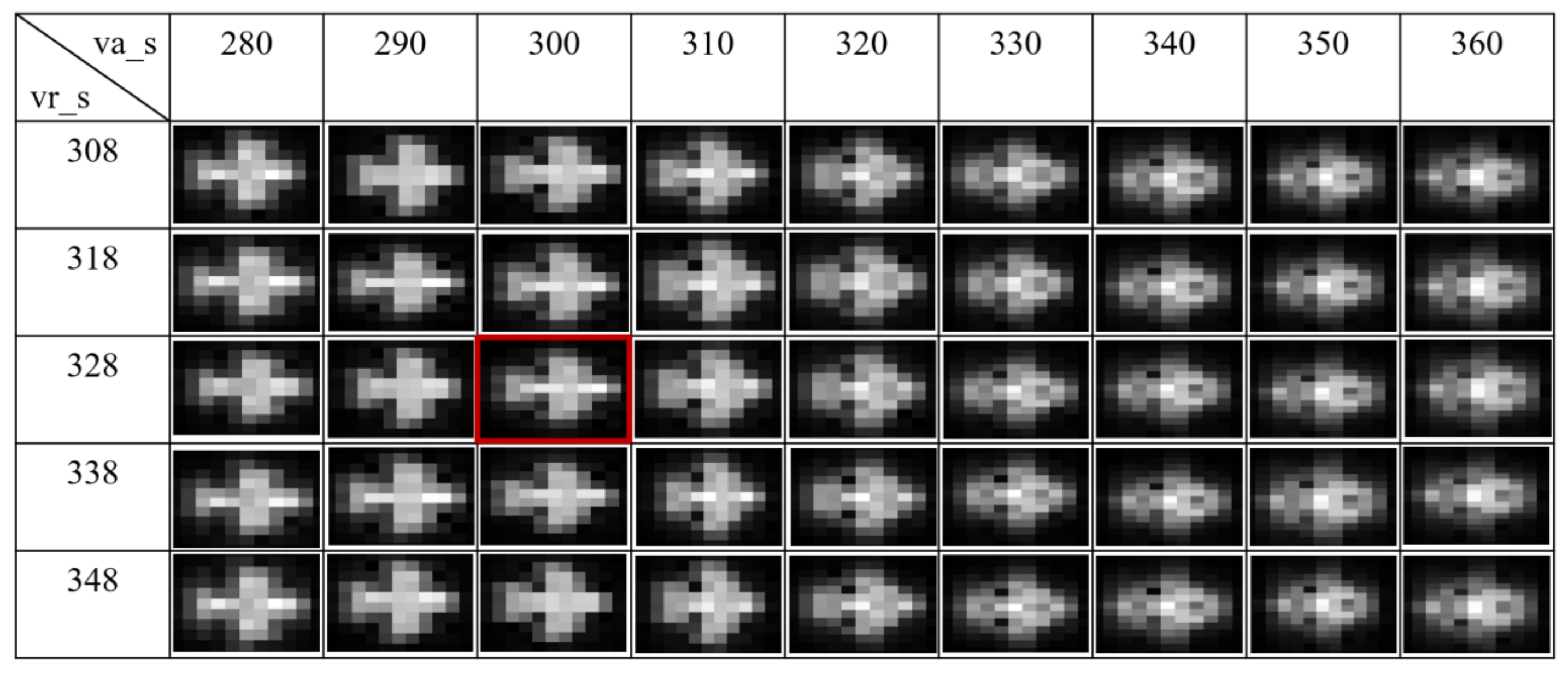
Based on the rough search results, the fine search velocity group is reset. The radial search velocity ranges from 308 m/s to 348 m/s, and the search velocity interval is 10 m/s. The tangential search velocity ranges from 280 m/s to 360 m/s, the search velocity interval is 10 m/s. The above two-dimensional search velocity parameter group is used for the refined search, and the results are shown in Figure 15.

Figure 15.
Focused target imaging for different refined search velocity groups.
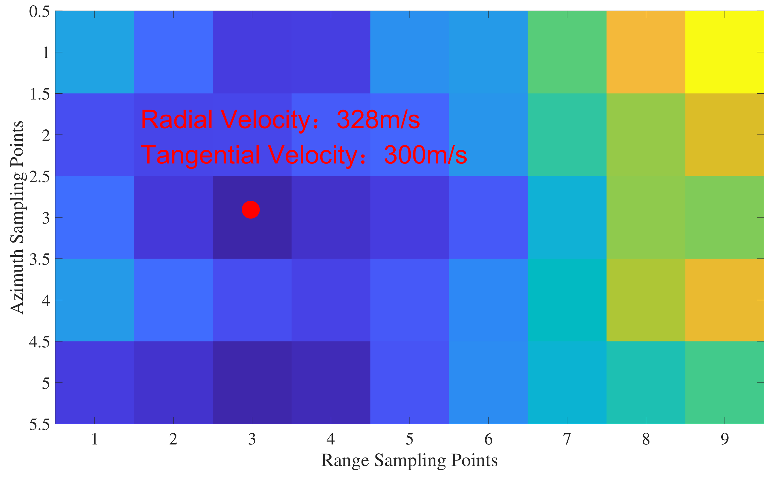
Its corresponding Shannon entropy is calculated for the aerial target focusing imaging results under different refined search velocity groups and stored sequentially according to the search velocity groups, as shown in Figure 16.
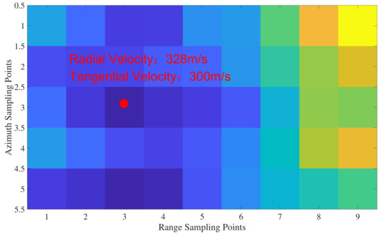
Figure 16.
Shannon entropy results for different refined search speed groups.
The result of the refined search shows that the radial velocity of the aerial target is 328 m/s, and the tangential velocity is 300 m/s. The above results show that the refined search under the premise of rough search results, also using the Shannon entropy as an index, can select the search velocity group closest to the actual velocity of movement, the Shannon entropy in the above results is still in a continuous state, and the index is still robust, which confirms the feasibility of the minimum Shannon entropy criterion in current algorithms.
The trend in Figure 15 is not as apparent as that in Figure 13, which is due to the smaller interval and higher precision of the refined search. However, it can still be seen that when the focused imaging is performed with the refined search results, the imaging profile and focusing effect are both optimal.
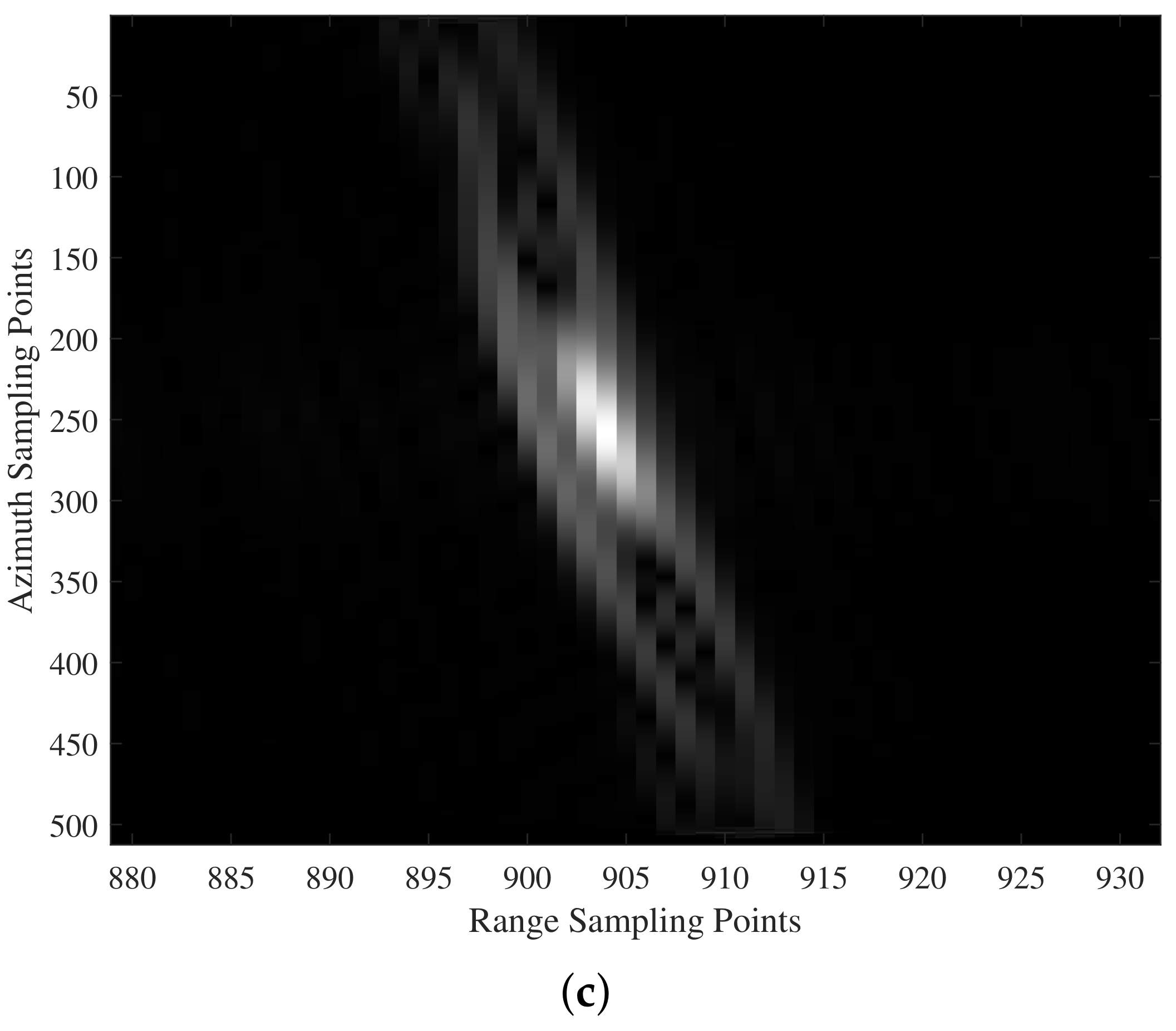
The velocity information obtained by the above two-dimensional velocity search is substituted into the aerial target BP focusing imaging algorithm, and the similarities and differences between the two focusing imaging results are compared by introducing the flight velocity of the actual aerial target, as shown in Figure 17.
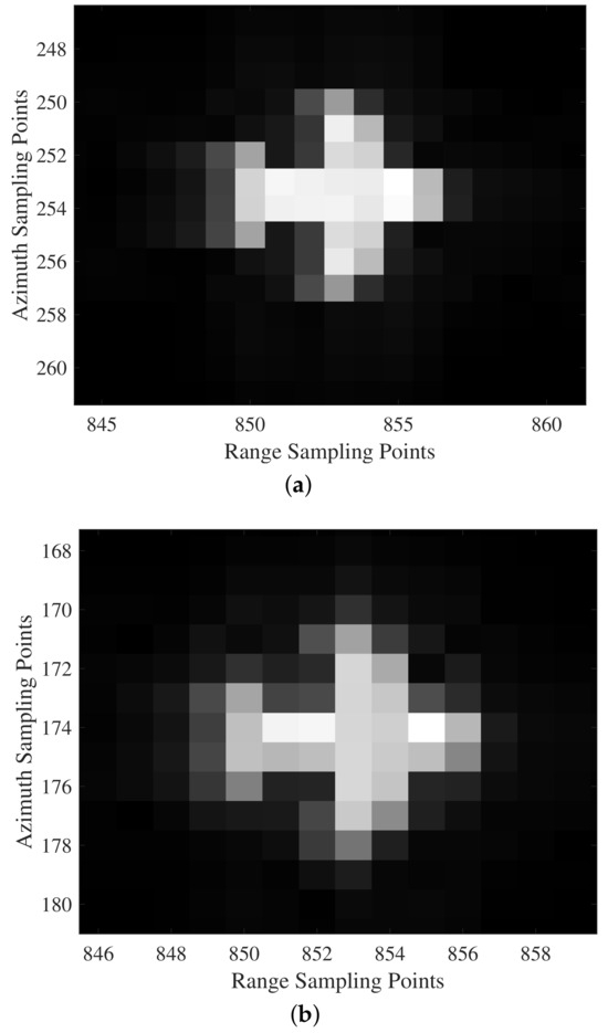
Figure 17.
Comparison of the similarities and differences between the derived search velocity imaging and the preset target imaging. (a) Real aerial target. (b) Bringing in search velocity imaging.
4. Discussion
As can be seen in Figure 17, an aerial moving target is simulated according to the actual flight velocity, and the pixel unit of the target is in the distance upwards from the 250th pixel to the 258th pixel; and in the orientation upwards, from the 848th pixel to the 856th pixel. Using the obtained search velocity group, the target is refocused imaging, and the pixel unit of the target is in the azimuth upward, from the 170th pixel to the 180th pixel, and in the orientation up from the 848th pixel to the 856th pixel. Under the condition of error allowance, the algorithm can satisfy the basic requirements of searching, detecting, and imaging the moving target, and obtain the relatively accurate moving velocity. Analyzed from the perspective of each pixel point amplitude, the average error is 4.1512%. The above results show that the algorithm can meet the basic requirements of imaging and can relatively accurately depict and recognize the shape contour of the moving target.
The above experimental results verify the accuracy of clutter suppression when there is an aerial target. At the same time, provide the primary conditions for velocity search to avoid clutter interference and noise on the aerial target. At the same time, for each point, due to the high-speed movement of each other, there will be an uneven distribution of the upper amplitude, but it does not affect the final results of the discrimination and search.
5. Conclusions
In this paper, based on the spaceborne SAR system, the two-dimensional velocity search is combined with the classical radar imaging algorithm to realize the integrated processing of detection–focused imaging parameter estimation for the moving target. Firstly, the different preprocessing methods for ground/sea detection are analyzed; ground detection requires distance compression followed by clutter suppression, and ground detection only requires distance compression. Secondly, the Radon transform and CFAR detection are carried out on the preprocessed data to determine the position and center of the aerial target and intercept the distance units where the aerial target is located. Thirdly, the two-dimensional search velocity group is set up, and BP focusing imaging is performed. The rough search and refined search are carried out successively. The minimum Shannon entropy criterion is selected as an index to select the two-dimensional velocity group, which is brought in, and focusing imaging is performed. Finally, simulation experiments verify the proposed algorithm’s feasibility and accuracy. The analysis shows that this algorithm can be well used for parameter estimation and focusing imaging of the aerial target detection.
Author Contributions
Conceptualization, H.Y.; methodology, H.Y.; software, J.H.; validation, J.H.; formal analysis, H.L.; investigation, H.L., W.X. and Z.M.; data curation, J.H.; writing—original draft, J.H.; writing—review editing, J.H.; supervision, H.Y.; project administration, H.Y.; funding acquisition, D.Z. All authors have read and agreed to the published version of the manuscript.
Funding
This research was funded by the National Natural Science Foundation of China (grant number 62271252 and 62171220).
Data Availability Statement
The raw data supporting the conclusions of this article will be made available by the authors on request.
Conflicts of Interest
The authors declare no conflict of interest.
References
- Chiu, S.; Dragošević, M. An efficient algorithm for fully capturing a ground moving target’s energy for spaceborne SAR-GMTI. In Proceedings of the 2011 IEEE RadarCon (RADAR), Kansas City, MO, USA, 23–27 May 2011; pp. 288–293. [Google Scholar]
- Xi, L.; Zhang, C. A kind of dual-channel GMTI real-time processing method based on frequency DPCA. In Proceedings of the 2006 CIE International Conference on Radar, Shanghai, China, 16–19 October 2006; pp. 1–4. [Google Scholar]
- Li, Z.; Wu, J.; Li, W.; Huang, Y.; Yang, J. Dual-Channel DPCA technique in Bistatic Forward-looking SAR for moving target detection and imaging. In Proceedings of the 2011 IEEE CIE International Conference on Radar, Chengdu, China, 24–27 October 2011; Volume 1, pp. 942–945. [Google Scholar]
- Liang, Z.; Wang, J.; Li, G. Brief Analysis on SAR Technology and Application of Spaceborne SAR. Geomat. Spat. Inf. Technol. 2021, 44, 29–32. [Google Scholar]
- Mu, H. Research on Ground Moving Target Detection and Inaging in Multichannel SAR System. Ph.D. Thesis, Harbin Institute of Technology, Harbin, China, 2021. [Google Scholar]
- Hong, Z.; Bao, G. Review of radar automatic target recognition based on ensemble learning. J. Comput. Appl. 2024. [Google Scholar]
- Zhang, H.P.; Xu, Y.Q.; Zhang, X.Y.; Deng, Z.R. Dual-channel SAR slow moving target detection method based on multi-look and magnitude-phase joint. In Proceedings of the 2022 2nd International Conference on Computer Science, Electronic Information Engineering and Intelligent Control Technology (CEI), Nanjing, China, 23–25 September 2022; pp. 389–394. [Google Scholar] [CrossRef]
- Zhou, Z.; Ding, Z.; Zhang, T.; Wang, Y. High-Squint SAR Imaging for Noncooperative Moving Ship Target Based on High Velocity Motion Platform. In Proceedings of the 2018 China International SAR Symposium (CISS), Shanghai, China, 10–12 October 2018. [Google Scholar]
- Jin, G.; Zhang, X.; Huang, J.; Zhu, D. High Freedom Parameterized FM (HFPFM) Code: Model, Correlation Function and Advantages. IEEE Trans. Aerosp. Electron. Syst. 2024, 1–15. [Google Scholar] [CrossRef]
- Zhang, R.; Yang, S.; Zhang, Q.; Xu, L.; He, Y.; Zhang, F. Graph-based few-shot learning with transformed feature propagation and optimal class allocation. Neurocomputing 2022, 470, 247–256. [Google Scholar] [CrossRef]
- Zhang, R.; Cao, Z.; Yang, S.; Si, L.; Sun, H.; Xu, L.; Sun, F. Cognition-Driven Structural Prior for Instance-Dependent Label Transition Matrix Estimation. IEEE Trans. Neural Netw. Learn. Syst. 2024. [Google Scholar] [CrossRef] [PubMed]
- Liu, G. Research on Imaging and Detection Metchod of Moving Target in SAR. Master’s Thesis, Electronic Science Research Institute of China Electronics Technology Group Corporation, Beijing, China, 2019. [Google Scholar]
- Gong, Z. Research on the Algorithm of Multichannel SAR-GMTI. Master’s Thesis, China Academy of Space Technology Xi’an Branch, Xi’an, China, 2021. [Google Scholar]
- Wang, Y.; Zong, Z. Moving Target Detection of Airborne SAR Based on Virtual Tri-channel Displaced Phase Center Antenna Approach. In Proceedings of the 2014 Seventh International Symposium on Computational Intelligence and Design, Hangzhou, China, 13–14 December 2014; Volume 1, pp. 347–350. [Google Scholar] [CrossRef]
- Wang, X.; Gao, G.; Zhou, S.; Zhu, Y. Performance comparison and assessment of displaced phase center antenna and along-track interferometry techniques used in synthetic aperture radar-ground moving target indication. J. Appl. Remote Sens. Soc. Photo-Opt. Instrum. Eng. 2014, 8, 083504. [Google Scholar] [CrossRef]
- Zheng, M. Synthetic Aperture Radar Moving Target Detection and Imaging Study. Ph.D. Thesis, Institute of Electrics Chinese Academy of Sciences, Beijing, China, 2003. [Google Scholar]
- Pu, X.; An, H.; Sun, Z.; Wu, J.; Li, Z.; Yang, J. GEO Spaceborne-Airborne Bistatic SAR Clutter Supression Using Improved DPCA Method. In Proceedings of the IGARSS 2022—2022 IEEE International Geoscience and Remote Sensing Symposium, Kuala Lumpur, Malaysia, 17–22 July 2022; pp. 559–562. [Google Scholar]
- Zhang, J.; Cheng, G.; Tang, J.; Xie, Z.; Wu, H. A Novel Imaging Algorithm for Wide-Beam Multiple-Receiver Synthetic Aperture Sonar Systems. Remote Sens. 2023, 15, 3745. [Google Scholar] [CrossRef]
- Zhang, Z.; Yu, W.; Zheng, M.; Zhao, L.; Zhou, Z.X. Phase Mismatch Calibration for Dual-Channel Sliding Spotlight SAR-GMTI. Remote Sens. 2022, 14, 617. [Google Scholar] [CrossRef]
- Yang, J.; Zhang, Y.; Mi, Y.P.; Shi, X. SAR Ground Moving Target Imaging With Adjacent Cross Correlation function. In Proceedings of the 2019 6th Asia-Pacific Conference on Synthetic Aperture Radar (APSAR), Xiamen, China, 26–29 November 2019. [Google Scholar]
- Jiang, Y.; Chen, Y.; Wang, Y.; Wang, W. The GMTI Technology of Spaceborn SAR. Aerosp. Shanghai 2009, 26, 60–64. [Google Scholar]
- Hou, Y.; Wang, J.; Liu, X.; Wang, K.; Gao, Y. An automatic SAR-GMTI algorithm based on DPCA. In Proceedings of the 2014 IEEE Geoscience and Remote Sensing Symposium, Quebec City, QC, Canada, 13–18 July 2014; pp. 592–595. [Google Scholar]
- Kang, Y.; Xiang, C.; Wang, W.; Yu, G. Small Target Detection Based on SAR Image Changes. Fire Control. Radar Technol. 2024, 53, 1–7. [Google Scholar]
- Zhang, R.; Xu, L.; Yu, Z.; Shi, Y.; Mu, C.; Xu, M. Deep-IRTarget: An automatic target detector in infrared imagery using dual-domain feature extraction and allocation. IEEE Trans. Multimed. 2021, 24, 1735–1749. [Google Scholar] [CrossRef]
- Zhang, R.; Tan, J.; Cao, Z.; Xu, L.; Liu, Y.; Si, L.; Sun, F. Part-Aware Correlation Networks for Few-shot Learning. IEEE Trans. Multimed. 2024. [Google Scholar] [CrossRef]
- Zhang, X.; Liu, B.; Lv, Z.; Wang, K.; Dai, Z.; Liu, L.; Liu, M. Efficient radon fractional Fourier transform for efficient motion parameters estimation in SAR-GMTI system. In Proceedings of the 2016 IEEE International Geoscience and Remote Sensing Symposium (IGARSS), Beijing, China, 10–15 July 2016. [Google Scholar]
- Yan, H.; Wang, J.; Huang, J.; WANG, X. A Moving-targets Detection Algorithm for Spaceborne SAR System Based on Two-dimensional Velocity Search Method. J. Electron. Inf. Technol. 2019, 41, 1287–1293. [Google Scholar]
- Li, R.; Yan, H.; Wu, C.; Zhao, R.; Zhang, J.; Zhu, D. Low-Flying Moving Target Detection and Imaging Algorithm of Spaceborne SAR Based on Two-Dimensional Velocity Search. In Proceedings of the 2022 14th International Conference on Signal Processing Systems (ICSPS), Zhenjiang, China, 18–20 November 2022; pp. 437–443. [Google Scholar] [CrossRef]
- Lou, R.; Zhao, L.; He, Q.; Ji, K.; Kuang, G. Intelligent technology for aircraft detection and recognition through SAR imagery: Advancements and prospects. J. Radars 2023, 13, 307–330. [Google Scholar]
- Zhao, X.; Liao, X.; Ding, Z.; Gao, W. A method for moving target detection based on airborne multi-aspect SAR system. In Proceedings of the 2016 IEEE International Conference on Signal Processing, Communications and Computing (ICSPCC), Hong Kong, China, 5–8 August 2016; pp. 1–5. [Google Scholar] [CrossRef]
- Xi, L.; Jinlin, N.; Guosui, L.; Yi, L.; Hong, G.; Weimin, S. Research on SAR/ISAR phase compensation technique based on image criterion. J. Electron. 2000, 22, 279–289. [Google Scholar]
- Wahl, D.E.; Eichel, P.; Ghiglia, D.; Jakowatz, C. Phase gradient autofocus—A robust tool for high resolution SAR phase correction. IEEE Trans. Aerosp. Electron. Syst. 1994, 30, 827–835. [Google Scholar] [CrossRef]
- Chen, J.; Chen, J.; Wang, S. Bistatic Radar DPCA Technique. In Proceedings of the 2006 CIE International Conference on Radar, Shanghai, China, 16–19 October 2006; pp. 1–4. [Google Scholar]
- Chen, C.; Qian, B.; Wang, S. DPCA motion compensation technique based on multiple phase centers. In Proceedings of the 2011 IEEE CIE International Conference on Radar, Chengdu, China, 24–27 October 2011; Volume 1, pp. 711–714. [Google Scholar]
- Jiang, Y.; Wang, L.; Ling, Q.; Ma, J.; Huang, P.; Liu, X.; Fan, J. Spaceborne HRWS-SAR-GMTI System Design Method with Optimal Configuration. Remote Sens. 2024, 16, 2148. [Google Scholar] [CrossRef]


Disclaimer/Publisher’s Note: The statements, opinions and data contained in all publications are solely those of the individual author(s) and contributor(s) and not of MDPI and/or the editor(s). MDPI and/or the editor(s) disclaim responsibility for any injury to people or property resulting from any ideas, methods, instructions or products referred to in the content. |
© 2024 by the authors. Licensee MDPI, Basel, Switzerland. This article is an open access article distributed under the terms and conditions of the Creative Commons Attribution (CC BY) license (https://creativecommons.org/licenses/by/4.0/).