Abstract
The passive estimation of harmonic sound source depth is of great significance for underwater target localization and identification. Passive source depth estimation using a single hydrophone with an unknown seabed geoacoustic property is a crucial challenge. To address this issue, a harmonic sound source depth estimation algorithm, seabed independent depth estimation (SIDE) algorithm, is proposed. This algorithm combines the estimated mode depth functions, modal amplitudes, and the sign of each modal to estimate the sound source depth. The performance of the SIDE algorithm is analyzed by simulations. Results show that the SIDE is insensitive to the initial range of the sound source, the source depth, the hydrophone depth, the source velocity, and the type of the seabed. Finally, the effectiveness of the SIDE algorithm is verified by the SWellEX-96 data.
1. Introduction
Acoustic methods for localizing a source, particularly a submerged source, in an underwater acoustic waveguide is a topic of great interest. As an important part of source localization, the depth estimation has particular difficulties but is of great significance to the identification of underwater targets.
Many methods have been proposed for source depth estimation. One of the most popular methods is the matched field processing (MFP) [1,2], which matches the measured field and the replica field for source depth estimation. The MFP can estimate source depth accurately without considering any environmental mismatches. However, when the sound propagation is not exactly modeled, the performance of depth estimation by the MFP degrades greatly, which is referred to as the environmental mismatch problem (EMP). In the MFP, the depth estimation depends on the range estimation, which indicates that an erroneous estimation of the source range would have serious consequences for the depth estimation. Compared with the MFP, matched mode processing (MMP) [3,4,5] can estimate the source range and depth separately and is less sensitive to environmental mismatches. Noting that source depth determines the amplitudes of excited modes, the MMP can determine the source depth by matching the mode amplitudes extracted from real data with the simulated excitation modal amplitudes of the sound source at different depths. However, the MMP is still bothered by the EMP in applications. Moreover, the resolution in the depth direction is poor when only mode amplitudes are used for depth estimation. To extract the mode amplitudes accurately, a full-depth vertical linear array (VLA) [6,7] or a horizontal linear array (HLA) with a large aperture [8,9] is required. Nevertheless, it is difficult to meet the above conditions in many application scenarios. In order to alleviate the effect of the EMP, machine learning (ML) methods have been introduced for underwater source location in recent years [10,11,12,13,14], and they show better performance than the MFP or the MMP in both ranging and depth estimation. Although the ML methods perform well in terms of positioning accuracy and adaptability to the environment in underwater acoustics, they often require a large number of training samples. It is difficult to meet that in many underwater applications. In addition, the interpretability issue of ML has not been resolved, which also limits its promotion in the field of underwater acoustics. An alternative method for overcoming the EMP is MMP based on data-derived modal parameters (mode depth functions and wavenumbers) [15,16]. Nevertheless, a larger aperture is also required to guarantee accuracy. To solve the problem of insufficient aperture, some research works have tried to use the idea of synthetic aperture [17,18] to obtain long-distance spatial sampling via the source motion, but the speed of a moving source is generally unknown. Although the smooth-averaged cross-correlation function of signals recorded by two horizontally separated hydrophones can be used for depth estimation of a source when the speed of the source in unknown [19], this method requires a broadband signal of the sound source and is not suitable for a harmonic source.
Recently, Hongxu Cui et al. proposed a method called the mode depth function constrained modal Doppler velocity estimation (MDFMD-v) method to estimate the velocity of a harmonic source in shallow water [20]. In this method, the harmonic source radiation signal only needs to contain two different frequencies, and no seabed geoacoustic information is required. Combining the MDFMD-v method, this paper introduces a algorithm for harmonic source depth estimation using a single hydrophone. In our algorithm, only the sound speed profile (SSP) of shallow water needs to be known. To address the problem of low depth direction resolution caused by the traditional MMP using only modal amplitudes for depth estimation, this paper proposes a method called seabed independent depth estimation (SIDE). In the SIDE algorithm, a one-dimensional mode sign search algorithm called depth-sign search (DSS) is introduced to obtain the sign information of each mode. Combining the searched modal signs and the extracted modal amplitudes, the SIDE algorithm can improve the depth estimation accuracy effectively. The performance of the SIDE algorithm is analyzed by numerical simulation in this paper, and the simulation results show that the performance of the SIDE algorithm is insensitive to source depth, hydrophone depth, range between source and hydrophone, source velocity, and type of the seabed. When the time domain signal-to-noise ratio (TSNR) is 0 dB, the average relative error of the source depth estimation by the SIDE algorithm is less than 7%, which is far less than that of the conventional MMP with an average relative error of more than 20% under the same condition. Moreover, the effect of TSNR on the SIDE algorithm is analyzed, and the results show that the average relative error of the depth estimation results is less than 12% when the TSNR is greater than −20 dB. Finally, the effectiveness of the SIDE algorithm is validated by the SwellEx-96 data [21].
The innovations of this paper are as follows:
- The seabed independent depth estimation (SIDE) algorithm is proposed, which can realize the source depth estimation without the information of the seabed parameters and the source velocity.
- The depth-sign search (DSS) method is proposed, which can transform the multi-dimensional mode-sign search problem into a one-dimensional search problem, improving the search efficiency significantly.
- The performance of the SIDE algorithm is analyzed by simulation, and the effectiveness of the SIDE algorithm is verified by the Swell-Ex96 data.
The structure of this paper is as follows. Section 2 is the preliminary, where the necessary preparatory knowledge for the SIDE algorithm will be introduced. The theory of the SIDE algorithm is introduced in Section 3, and the DSS is also introduced in this section. In Section 4, the performance of the SIDE algorithm is analyzed by simulations. The effectiveness of the SIDE algorithm is validated by the date in the Swell-Ex96 in Section 5. Finally, conclusions are given in Section 6.
2. Preliminary
In order to ensure the theoretical integrity of the article, before introducing the SIDE algorithm, we first introduce the modal Doppler effect and briefly describe the MDFMD-v, which utilizes the modal Doppler effect to estimate the velocity and frequency of a moving source.
Consider a range-independent waveguide as shown in Figure 1 and assume that a point source is approaching the hydrophone with radial velocity . The source transmits signal , with being the intrinsic angular frequency of the source. The range between the source and the hydrophone is unknown, and the source depth is assumed to be a constant. According to the normal mode theory, the sound field received by the hydrophone can be expressed as [22]
where M denotes the number of propagating modes; is the range between the source and the hydrophone at time t, with being the initial range; and are the horizontal wavenumber and the mode depth function of mode m, respectively; and and represent the depth of source and hydrophone, respectively. In Equation (1),
which means that the motion of the sound source causes a frequency shift in the received signal. And the frequency shift of different modes is different, which is the modal Doppler effect.
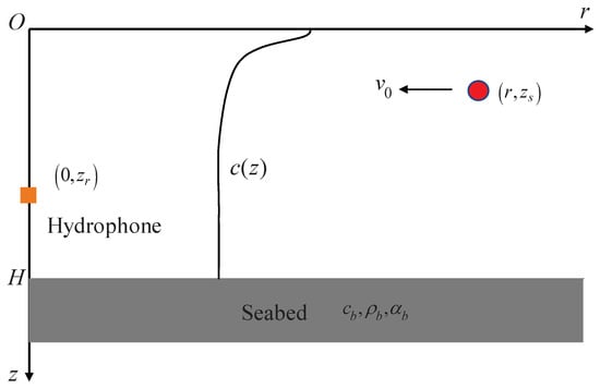
Figure 1.
A harmonic source approaches the hydrophone at velocity in a range-independent waveguide.
The MDFMD-v method can estimate the harmonic sound velocity when seabed parameters are unknown. This method combines the modal Doppler and the homomodal similarity (HS) proposed in [20] to realize the estimation of the source velocity. The HS means that the mode depth functions usually vary slowly with frequency, so the mode depth functions excited by two adjacent frequencies are almost the same with high correlation. From Equation (1), one can find that and are coupled. In the MDFMD-v, the HS is utilized to decouple and , in which the intrinsic relationship between the horizontal wavenumbers and the mode depth functions are needed. Taking the normal mode as an example, the horizontal wavenumber and the corresponding mode depth function are related by the following differential equation:
where
and is the SSP of the water column. According to reference [7], the above equation can be discretized to the following difference equation:
where is the difference step. Therefore, can be calculated when and are known by the following equation:
where , , . Define
where with , , H is the water depth, , and ‘T’ represents the matrix transpose. Then, the HS can be judged by calculating the correlation coefficient of the same mode depth function at two different frequencies, which can be approximated by
where ‘H’ represents the conjugate transpose.
Assume that a moving source emits signals at two adjacent frequencies and . In passive detection, both the velocity and the frequencies of the moving source are unknown. Due to the modal Doppler effect, the frequencies of the received signal consist of and , where and with and . Although it is difficult to accurately obtain the frequencies of the source, an approximate range of the two frequencies can be determined by spectral analysis. From the time–frequency analysis, one can determine the source frequencies search intervals According to experience, one can determine the velocity search interval Then, the mode depth functions corresponding to each and are calculated according to Equations (1) and (5). Let
and
represent the extracted mode depth functions at and respectively, where . Based on the fact that not all modes satisfy the HS when , the loss function for the moving source velocity estimation can be constructed as:
When the loss function is minimal, the correlation between and is the highest:
3. Theory of the SIDE Algorithm
In Section 2, we introduce the MDFMD-v method, which offers an innovative approach to estimating the velocity of a moving harmonic source without seabed information. Combining Equations (2) and (5), we can also calculate the horizontal wavenumbers and the corresponding mode depth functions.
After obtaining the horizontal wavenumbers and the mode depth functions, the MMP can be used to estimate the source range and the source depth at the same time, theoretically. However, considering the fact that target ranging errors will lead to target depth estimation errors, it is not wise to use the MMP method to estimate the target distance at the same time while only the target depth information is focused. Therefore, T. C. Yang proposed a method to estimate the depth independently [4]. This method utilizes only the normal mode amplitudes, and defines the source depth ambiguity function as
where represents the amplitude of the normal mode,
And the depth corresponding to the maximum value of is the estimation of the source depth. When the velocity of a moving source is known, can be estimated by the Hankel transform (HT) [23], and the source depth can be estimated by Equation (10). Due to only the mode amplitudes being used in Equation (10), the depth estimation method proposed by T. C. Yang is sensitive to the estimation results of the amplitude of each mode, which shows a high sidelobe. In addition, when the estimation results of the amplitude of each mode are biased due to seabed attenuation and other factors, the sidelobe peak value may be higher than that of the main lobe. This will lead to the wrong depth estimation.
Different from the method proposed by T. C. Yang, not only the mode amplitudes but also the mode signs are used for source depth estimation in the SIDE algorithm. Actually, the source depth information is modulated simultaneously on the amplitude and sign of each normal mode. Moreover, the sign of each mode is coupled with the propagation phase of each mode, which is difficult to obtain when the distance of the sound source is unknown. A naive method for obtaining modal signs is to try all possible combinations of modal signs by ergodic search. However, the number of all possible combinations of mode signs increases exponentially with the number of modes M. And the efficiency of the ergodic search method is low when the number of modes in the ocean waveguide is large. In addition, in order to obtain the real sign of each mode, it is also necessary to set the sign discrimination standard. Based on the current research, neither the efficient search method of modal signs nor the correctness judgment method of modal signs have been studied. The DSS method, a fast search method for modal sign, which is a component of the SIDE algorithm, is introduced first. And then we give the correctness judgment criteria of the searches’ modal signs.
From Equation (11), it is easy to find that the signs of are only influenced by and , where . Generally, the hydrophone depth is a known parameter. When the mode depth functions have been extracted, are known, and the signs of are only determined by , which means that an ergodic search for all meaningful combinations of modal signs can be achieved by searching only for a single parameter . So, this modal sign search method is named depth-sign search (DSS).
To judge the correctness of the modal signs, we combine the DSS with the source depth estimation process. Firstly, we construct the sign scalar
where , and
can be considered an estimation of the mth modal sign. Based on Equation (10), we define a new source depth ambiguity function by considering :
According to reference [24], closely approximates the Dirichlet kernel function when is the correct modal signs. Leveraging this property, a loss function can be devised to measure the discrepancy between and that of the Dirichlet kernel. The KL divergence is chosen here to measure the difference between and the Dirichlet kernel:
where the integral operation can be approximated by discrete summation,
is the Dirichlet kernel. is a small quantity to avoid being zero. In this paper, we take . Then, the correct modal signs can be determined by
where . When both the modal amplitudes and modal signs are obtained, a joint source depth estimation function can be defined as Equation (16) by considering at least two different frequencies which are needed in the MDFMD-v:
where . Since the aforementioned process of sound source depth estimation does not incorporate any seabed information, we refer to the method of sound source depth estimation as the seabed independent depth estimation method (SIDE) algorithm. The pseudocode implementation of the SIDE algorithm is presented in Algorithm 1. In the following sections, the performance of the SIDE algorithm will be analyzed through simulations in Section 4 and subsequently validated with experimental data presented in Section 5.
| Algorithm 1 SIDE |
|
4. Simulation
In this section, the performance of the SIDE algorithm will be analyzed by simulations. In our analysis, we focus on the effects of hydrophone depth, source depth, source velocity, initial distance between source and hydrophone, signal-to-noise ratio, and seabed type on the SIDE algorithm.
Firstly, consider the waveguide as depicted in Figure 1. The SSP is selected from the SWellEX-96 experiment, illustrated in Figure 2b, with specific seabed information denoted as , , , and the depth of water . The source, whose depth is , approaches the hydrophone from position at a constant velocity , and emits a signal , where , . The time domain waveform (within a 1 s observation window) is shown in Figure 3a. And Figure 3b is the normalized spectrum of the emitted signal. The hydrophone is positioned at a depth of , and the initial distance between the source and the hydrophone is 10 km. The received signal with a 1 s observation window is shown in Figure 3c. In order to simulate the influence of environmental noise, white Gaussian noise has been added to the received signal, and the TSNR is 0 dB. Figure 3d shows the normalized spectrum of the received signal. In order to observe the modal Doppler, the length of the time window of the Fourier transform (FT) is set as 2000 s to ensure adequate frequency resolution. From Figure 3d, one can clearly see the line spectrum splitting phenomenon caused by the mode Doppler effect. In addition, the amplitude of each modal Doppler frequency is approximated as the amplitude of each mode. It is assumed that the source is a non-cooperative source with unknown velocity and frequency during the data processing.
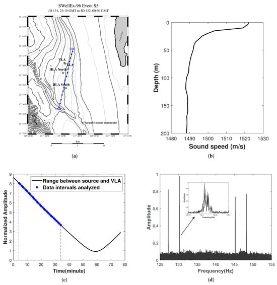
Figure 2.
The SwellEX-96 experiments. (a) Trajectory of the source movement for the S5 event and the locations of hydrophone arrays. (b) Seawater Sound Speed Profile (SSP). (c) The black solid line represents the range of the source relative to the vertical array, while the blue dotted line shows the data for the time period under analysis. (d) Frequency of signals emitted by the source during the S5 event, with the four line spectra of this analysis displayed in the blue box.
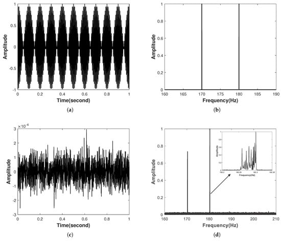
Figure 3.
(a) represents the time−domain waveform (within a 1 s observation window) emitted by the source. (b) The normalized spectrum of the emitted signal. Similarly, (c) represents the signal with noise considered received by the hydrophone (within a 1 s observation window). (d) The normalized spectrum of the received signal. And the window of Fourier transform is set as 2000s in order to observe the modal Doppler.
The velocity and frequencies of the source are estimated using the MDFMD-v method, and the results are shown in Figure 4. Note that the result of Equation (8) is a three-dimensional matrix corresponding to , and v, which will make it difficult to visualize the estimation results. To facilitate the presentation of the results, Figure 4 shows the results for the and the planes at the location of the minimum loss. searches from 160 Hz to 180 Hz at 0.1 Hz intervals, searches from 170 Hz to 190 Hz at 0.1 Hz intervals, and v searches from 0 m/s to 8 m/s at 0.1 m/s intervals. In Figure 4, the white circles represent the locations of the real source velocity and frequencies. And the frequencies and velocity estimation results are , Hz and , which are well matched with the real.
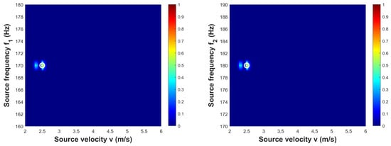
Figure 4.
The source velocity and frequencies results for the and the plane at the location of the minimum loss. And the velocity search interval is 0.01 m/s, and the frequency search interval is 0.1 Hz. The white circles denote the true source velocity and frequencies, and the estimated source frequencies and velocities are , , and , respectively.
Upon determining the source velocity and frequencies, the horizontal wavenumbers and the corresponding mode depth functions can be computed by Equations (2) and (5), and the amplitude of each mode can be estimated using the FT. Figure 5 illustrates the estimated horizontal wavenumbers and mode depth functions for the frequency , and all subsequent results pertain to the frequency unless explicitly specified. In Figure 5a, the red circle and blue cross symbols represent the estimated and the real horizontal wavenumbers, respectively. Similarly, in Figure 5b, the blue line and the red dashed lines represent the estimated and the real mode depth functions, respectively. Almost all of the correlation coefficients are larger than 0.99, except for the fourth mode with a correlation coefficient of 0.66. The poor estimation result for the lowest-order mode is mainly due to the fact that the source travel distance is smaller, resulting in inaccurate horizontal wavenumber estimation of the lowest normal mode. Inaccurate estimation of the horizontal wavenumber will lead to inaccurate estimation of the mode depth function.
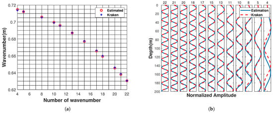
Figure 5.
Estimated horizontal wavenumbers and mode depth functions. (a) The comparison of the estimated horizontal wavenumbers (red circle) with horizontal wavenumbers calculated by Kraken (blue cross symbol). (b) The comparison of the estimated mode depth function with the mode depth function calculated by Kraken. The above results are derived from the frequency .
Figure 6a illustrates the normalized amplitudes of modal Doppler frequencies. Here, the normalized amplitudes mean that the largest amplitude is one. As a reference, normalized modal amplitudes calculated by Equation (11) for different modes are also given in Figure 6a. Figure 6b shows the loss function defined by Equation (14) evolution during the optimization process utilizing DSS. It can be found that the value of the loss function is the smallest near the true depth of the sound source.
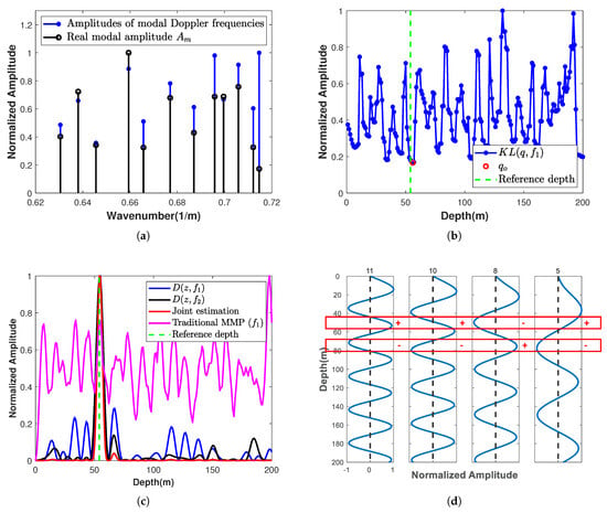
Figure 6.
(a) The amplitudes of modal Doppler frequencies and that calculated by Equation (11). (b) Loss function evolution during DSS exploration (blue dotted line) with the loss function minimum denoted by the red circle. (c) Depth ambiguity functions computed using frequencies (blue solid line) and (black solid line), as well as from joint estimation (red solid line) and traditional MMP (magenta solid line). The true source depth is represented by the green vertical dashed line. (d) Mode depth functions sharing identical sign combinations within the range delineated by the red box.
Figure 6c exhibits the depth ambiguity function computed by the SIDE algorithm under various scenarios: individual estimation for , , and the joint estimation. For comparison, the result estimated by traditional MMP is also given in Figure 6c. In the cases of individual estimation for , , and joint estimation, the sign combinations are chosen based on the minimization of the loss function. In Figure 6c, we can find that the results estimated by the SIDE algorithm, , have very low sidelobes for both the single line spectrum and joint estimation. In contrast, the conventional MMP method, despite the presence of a peak at the depth of the sound source, has high sidelobes, and the highest peak occurs at , with a large estimation error. Notice that the loss function minimum in Figure 6b is located at the source depth, but this is not necessarily the case in practice. As in Figure 6d, the signs of the mode depth functions in the red boxes are the same.
To evaluate the performance of the SIDE algorithm, we analyze the source depth estimation performance of the SIDE algorithm under different initial ranges of the source, source depth , hydrophone depth , and source velocity . The initial range of the source is varied from 6 km to 15 km in increments of 0.2 km, the source velocity varied from 1 m/s to 8 m/s in increments of 0.1 m/s, and both source depth and hydrophone depth are varied from 1 m to 200 m with increments of 1 m. When we analyze the effect of one of the parameters on the SIDE algorithm, the values of the other parameters are consistent with the initial simulation. The simulation results presented in Figure 7 are the root mean square error (RMSE) obtained from 400 independent Monte Carlo experiments, and the RMSE is defined as
where is the number of independent Monte Carlo experiments, is the depth estimation result for the ith independent Monte Carlo experiment, and is the real source depth.
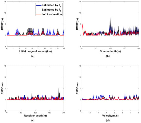
Figure 7.
Impact of various factors on the SIDE algorithm. (a) Impact of initial range of the source. (b) Impact of source depth. (c) Impact of hydrophone depth. (d) Impact of source velocity.
In Figure 7, the blue line represents the RMSE of frequency , the black line represents the RMSE of frequency , and the red line represents the RMSE of the joint estimate. In addition, the blue, black, and red regions are the range of standard deviations of the results for , , and joint estimation, respectively. From Figure 7, it is evident that the SIDE algorithm achieves low RMSE in depth estimation when .
The results in Figure 7 suggest that the initial range of the source, the source velocity, the hydrophone depth, and the source depth have little impact on the performance of the SIDE algorithm, and the average relative error in the source depth estimation is less than 7% when . The average relative error is defined by Equation (18). For comparison, the traditional MMP was conducted to estimate the source depth under the same conditions. Results are shown in Figure 8, where the standard deviation of the estimation results is not given as in Figure 7 because the traditional MMP estimation results are very unstable. Compared with Figure 7, it is easy to find that the accuracy of the sound source depth determination by the traditional MMP is not high, and the average relative error is more than 20%. This indicates that the traditional MMP is sensitive to the source velocity, the hydrophone depth, and the source depth:
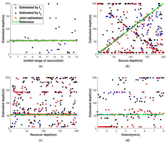
Figure 8.
Impact of various factors on the traditional MMP. (a) Impact of initial range of the source. (b) Impact of source depth. (c) Impact of hydrophone depth. (d) Impact of source velocity.
For a more comprehensive analysis of the performance of the SIDE algorithm, it is essential to examine the impact of SNR on the SIDE algorithm. Figure 9 illustrates the source depth estimation results across different SNR and compares them with the traditional MMP, with the time-domain SNR varying from −40 dB to 0 dB in increments of 2.5 dB.
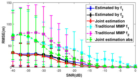
Figure 9.
Results of the SIDE algorithm and the traditional MMP at different SNR.
In Figure 9, the blue, black, and red lines show the results estimated using the SIDE algorithm, indicating the RMSE for frequencies , , and the joint estimation, respectively. Similarly, the cyan, pink, and green lines are the RMSEs for the conventional MMP. Figure 9 shows that the SIDE algorithm outperforms the traditional method. The SIDE algorithm has a RMSE of less than 10 m at for both the single line spectrum and the joint estimation. Additionally, joint estimation exhibits lower errors compared to single line spectrum estimation.
To demonstrate the impact of the seafbed on the SIDE algorithm, we tested the source depth estimation performance of the SIDE algorithm under different seabed parameter conditions. Consider a multi-layered seabed with sedimentary layer, the environment in this simulation are shown in Figure 10. The SSP is kept the same as the previous one. And the seabed consists of two layers and an elastic half-space. Layer 1 can be considered the sedimentary layer. And the parameters of Layer 1 have six cases as shown in Table 1. The seabed type can be changed by changing the parameters of Layer 1. For Layer 2, which has fixed parameters, its densities , compression wave velocity , attenuation of compression wave , shear wave velocity , shear wave attenuation , and thickness is 40 m. The elastic half-space density , compression wave velocity , attenuation of compression wave , shear wave velocity , and shear wave attenuation . During the test, SNR is fixed at 0 dB. In addition, the results in Table 1 are obtained by averaging the results of 400 independent Monte Carlo experiments, and is true source depth, and and are the mean and standard deviation of the 400 Monte Carlo experiments, respectively.
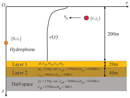
Figure 10.
A multi-layered seabed with sedimentary layers. Layer 1 can be considered the sedimentary layer. And the parameters of Layer 1 have six cases as shown in Table 1.

Table 1.
The estimation results of source depth with different Layer 1.
Table 1 indicates that the seabed type has little impact on the SIDE algorithm. To further discuss the effect of the ocean waveguide on the SIDE algorithm, we vary the SSP and water depth of the waveguide. Figure 11 illustrates a typical negative gradient (NG) SSP waveguide (Figure 11a) and a Pekris (Figure 11b) waveguide with multi-layered sedbed. Layer 1 is slit, and its parameters are shown in Table 1. The sound speed of the Pekris waveguide is 1500 m/s. In addition, the water depths H are set to be 50 m, 100 m, and 200 m, respectively. Similarly, 0 dB Gaussian noise is added, and 400 Monte Carlo experiments are performed. The source depth, receiver depth, and results are shown in Table 2. The rest of the simulation conditions are the same as before.
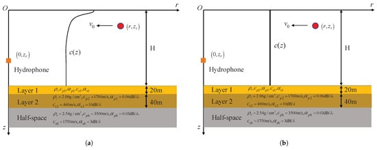
Figure 11.
(a) A negative gradient SSP waveguide with multi-layered seabed. (b) A Pekris waveguide with multi-layered seabed.

Table 2.
The estimation results of source depth with different SSP and water depth.
From Table 2, we can find that the variations in the SSP and depth of the waveguide have little impact on the SIDE algorithm, and the relative errors in the depth estimation are all less than 7%.
5. Experiment
In this section, the efficacy of the SIDE algorithm is validated using data from the SWellEX-96 experiment, which includes the S5 and S59 events. Due to S5 events having more stable Doppler phenomena than S59 events, this section will use S5 events for method validation. The movement path of the two sources for the S5 event and the locations of the hydrophone arrays are illustrated in Figure 2a. The deep source is 54 m underwater, and the shallow source is 9 m underwater. The SSP is depicted in Figure 2b. The sources started their track south of all of the arrays and proceeded northward at a speed of 5 knots, and transmitted numerous tonals of various source levels between 49 Hz and 400 Hz. The VLA recorded the full 75 min event.
This section will perform method validation using 30 min of data, 5 min after the start of event S5, recorded by one hydrophone, which is the one closest to the seabed in the VLA (at a depth of 212.25 m). Along the trajectory, water depths predominantly range between 200 m and 220 m, with minimal variation in water depth, allowing it to be treated as a homogeneous waveguide. In Figure 2c, the range between the source and the vertical array is depicted, with the blue dotted line representing the data segment being analyzed. The shallow source frequencies of 127 Hz and 145 Hz, along with the deep source frequencies of 130 Hz and 148 Hz, are selected for examination. Throughout the data analysis process, we assume that the source velocity, frequency and range are unknown, and only the seawater SSP information is available.
The velocity and frequency of the two sources are estimated using the MDFMD-v method as shown in Figure 12. The and search interval is 0.1 Hz, and v search interval is 0.1 m/s. The frequencies and velocity estimation results for the shallow source are , and . The parameters estimation for the deep source are , and . The estimation results of the parameters are well matched with the experiment.
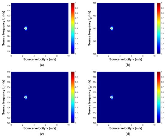
Figure 12.
Estimated sources frequencies and velocities by the MDFMD-v. (a,b) are the estimation results for shallow source with , , . (c,d) are the estimation results for deep source with , , .
Based on the velocity estimation result, the horizontal wavenumbers and the corresponding mode depth functions are computed by Equations (2) and (5), respectively. Then, the DSS is used to determine the optimal sign of each mode. The source depth can be estimated by combining the estimated mode signs, the mode depth functions and the modal amplitudes, and the estimated results are shown in Figure 13. Figure 13a shows the loss function defined by th evolution of Equation (14) during the optimization process, utilizing DSS. Figure 13b exhibits the depth ambiguity function computed under various scenarios: individual estimation for , , joint estimation, and traditional MMP. Similarly, Figure 13c,d show the estimation results for the deep source. Similar to the simulation, the traditional MMP has high sidelobes and large estimation error. For the SIDE algorithm, despite the poor estimation result for the deep source at , the joint estimation results are accurate. The joint estimation estimates depths of shallow source and deep source , and the relative error of the estimation results is less than 11%. In contrast, the results estimated by the traditional MMP method are 134 m and 45 m, respectively. And the relative errors are about 1388% and 16%, respectively, which are significantly larger than those of the SIDE algorithm.
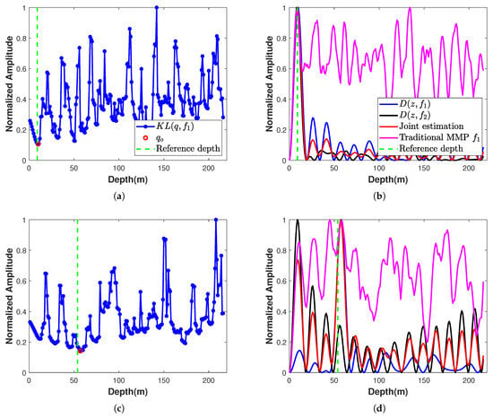
Figure 13.
Estimation results. (a) Loss function for shallow source sign search (blue dotted line), with red circles indicating the locations of the minima of the loss function. (b) Depth ambiguity functions computed using the sign combinations corresponding to the minima locations (red solid line). (c,d) represent the loss functions for deep source sign search (blue dotted line) and the depth ambiguity functions computed using the sign combinations at the minima locations (red solid line), respectively.
6. Conclusions
The SIDE algorithm is introduced to address the problem of depth estimation for a non-cooperative moving harmonic source when the seabed information is unknown. The SIDE algorithm enables passive depth estimation for a source that emits signals at two adjacent frequencies when only the SSP is known in a range-independent waveguide. In the SIDE algorithm, a one-dimensional sign search method called DSS is proposed to efficiently determine the modal amplitudes signs. DSS takes advantage of the property that the depth ambiguity function distribution closely resembles the Dirichlet kernel function when the signs align with those at the source depth. Simulations and SWellEx-96 experimental data validate the effectiveness of the SIDE algorithm for source depth estimation. In the simulations, we can find unexplained fluctuations in the depth estimation results; although these fluctuations have small peaks, they still need to be further explored in the future. Furthermore, with this method, it takes a long time to observe the modal Doppler effect, and it will be necessary to consider reducing this time in the next works. Finally, the current method focuses solely on scenarios where the source moves at a consistent speed in a horizontally uniform waveguide with minimal variations in water depth. Further investigations are warranted for sources moving at uniform or non-uniform velocities in range-dependent waveguides.
Author Contributions
Conceptualization, X.L. and Y.X.; methodology, X.L.; validation, X.L., Y.X. and W.G.; formal analysis, X.L.; investigation, Y.X.; resources, X.L. and Y.X.; data curation, Y.X.; writing—original draft preparation, Y.X.; writing—review and editing, X.L. and Y.X.; visualization, X.L.; supervision, W.G.; project administration, W.G., H.W. and L.W.; funding acquisition, X.L., W.G., H.W. and L.W. All authors have read and agreed to the published version of the manuscript.
Funding
This study was supported by the National Natural Science Foundation of China under grant numbers 52071309 and 52001296, the Taishan Scholars under grant number tsqn 201909053 and the Fundamental ResearchFunds for the Central Universities under grant numbers 202065005 and 862001013102.
Data Availability Statement
Restrictions apply to the availability of these data. Data were obtained from Marine Physical Laboratory of University of California San Diego and are available http://swellex96.ucsd.edu/ (accessed on 14 June 2023) with the permission of Marine Physical Laboratory.
Acknowledgments
The authors thank Shoudong Wang and Hongxu Cui for the insightful discussions and instructive guidance.
Conflicts of Interest
The authors declare no conflicts of interest.
References
- Baggeroer, A.B.; Kuperman, W.A.; Mikhalevsky, P.N. An overview of matched field methods in ocean acoustics. IEEE J. Ocean. Eng. 1993, 18, 401–424. [Google Scholar] [CrossRef]
- Tolstoy, A.D. Matched Field Processing for Underwater Acoustics; World Scientific: Singapore, 1993. [Google Scholar]
- Shang, E. Source depth estimation in waveguides. J. Acoust. Soc. Am. 1985, 77, 1413–1418. [Google Scholar] [CrossRef]
- Yang, T. A method of range and depth estimation by modal decomposition. J. Acoust. Soc. Am. 1987, 82, 1736–1745. [Google Scholar] [CrossRef]
- Bogart, C.W.; Yang, T. Comparative performance of matched-mode and matched-field localization in a range-dependent environment. J. Acoust. Soc. Am. 1992, 92, 2051–2068. [Google Scholar] [CrossRef]
- Neilsen, T.B.; Westwood, E.K. Extraction of acoustic normal mode depth functions using vertical line array data. J. Acoust. Soc. Am. 2002, 111, 748–756. [Google Scholar] [CrossRef] [PubMed]
- Li, X.; Wang, P. Modal wavenumber extraction by finite difference vertical linear array data. JASA Express Lett. 2021, 1, 126002. [Google Scholar] [CrossRef] [PubMed]
- Nicolas, B.; Mars, J.I.; Lacoume, J.L. Source depth estimation using a horizontal array by matched-mode processing in the frequency-wavenumber domain. EURASIP J. Adv. Signal Process. 2006, 2006, 65901. [Google Scholar] [CrossRef]
- Le Courtois, F.; Bonnel, J. Wavenumber tracking in a low resolution frequency-wavenumber representation using particle filtering. In Proceedings of the 2014 IEEE International Conference on Acoustics, Speech and Signal Processing (ICASSP), Florence, Italy, 4–9 May 2014; pp. 6805–6809. [Google Scholar]
- Niu, H.; Reeves, E.; Gerstoft, P. Source localization in an ocean waveguide using supervised machine learning. J. Acoust. Soc. Am. 2017, 142, 1176–1188. [Google Scholar] [CrossRef] [PubMed]
- Huang, Z.; Xu, J.; Gong, Z.; Wang, H.; Yan, Y. Source localization using deep neural networks in a shallow water environment. J. Acoust. Soc. Am. 2018, 143, 2922–2932. [Google Scholar] [CrossRef] [PubMed]
- Chi, J.; Li, X.; Wang, H.; Gao, D.; Gerstoft, P. Sound source ranging using a feed-forward neural network trained with fitting-based early stopping. J. Acoust. Soc. Am. 2019, 146, EL258–EL264. [Google Scholar] [CrossRef] [PubMed]
- Li, X.; Song, W.; Gao, D.; Gao, W.; Wang, H. Training a U-Net based on a random mode-coupling matrix model to recover acoustic interference striations. J. Acoust. Soc. Am. 2020, 147, EL363–EL369. [Google Scholar] [CrossRef]
- Michalopoulou, Z.H.; Gerstoft, P.; Kostek, B.; Roch, M.A. Introduction to the special issue on machine learning in acoustics. J. Acoust. Soc. Am. 2021, 150, 3204–3210. [Google Scholar] [CrossRef]
- Wolf, S.N. Experimental determination of modal depth functions from covariance matrix eigenfunction analysis. J. Acoust. Soc. Am. 1987, 81, S64. [Google Scholar] [CrossRef]
- Hursky, P.; Hodgkiss, W.S.; Kuperman, W.A. Matched field processing with data-derived modes. J. Acoust. Soc. Am. 2001, 109, 1355–1366. [Google Scholar] [CrossRef] [PubMed]
- Yang, T. Data-based matched-mode source localization for a moving source. J. Acoust. Soc. Am. 2014, 135, 1218–1230. [Google Scholar] [CrossRef] [PubMed]
- Yang, T. Source depth estimation based on synthetic aperture beamfoming for a moving source. J. Acoust. Soc. Am. 2015, 138, 1678–1686. [Google Scholar] [CrossRef]
- Zhai, D.; Zhang, B.; Li, F.; Zhang, Y.; Yang, X. Passive source depth estimation in shallow water using two horizontally separated hydrophones. Appl. Acoust. 2022, 192, 108723. [Google Scholar] [CrossRef]
- Cui, H. Research on the Estimation Method of Target Motion Velocity Based on Multi-Modal Doppler. Master’s Thesis, Ocean University of China, Qingdao, China, 2023. [Google Scholar]
- The SWellEX-96 Experiment. Available online: http://swellex96.ucsd.edu/ (accessed on 14 June 2023).
- Song, H.C.; Baggeroer, A. The resolution of modal Doppler shifts in a dispersive oceanic waveguide. J. Acoust. Soc. Am. 1990, 88, 268–282. [Google Scholar] [CrossRef]
- Frisk, G.V.; Lynch, J.F. Shallow water waveguide characterization using the Hankel transform. J. Acoust. Soc. Am. 1984, 76, 205–216. [Google Scholar] [CrossRef]
- Cheney, M.; Kirsteins, I. Resolution of matched field processing for a single hydrophone in a rigid waveguide. J. Acoust. Soc. Am. 2022, 152, 3186–3197. [Google Scholar] [CrossRef] [PubMed]
Disclaimer/Publisher’s Note: The statements, opinions and data contained in all publications are solely those of the individual author(s) and contributor(s) and not of MDPI and/or the editor(s). MDPI and/or the editor(s) disclaim responsibility for any injury to people or property resulting from any ideas, methods, instructions or products referred to in the content. |
© 2024 by the authors. Licensee MDPI, Basel, Switzerland. This article is an open access article distributed under the terms and conditions of the Creative Commons Attribution (CC BY) license (https://creativecommons.org/licenses/by/4.0/).