Abstract
Precision Agriculture (PA) is an approach to maximizing crop productivity in a sustainable manner. PA requires up-to-date, accurate and georeferenced information on crops, which can be collected from different sensors from ground, aerial or satellite platforms. The use of optical and thermal sensors from Unmanned Aerial Vehicle (UAV) platform is an emerging solution for mapping and monitoring in PA, yet many technological challenges are still open. This technical note discusses the choice of UAV type and its scientific payload for surveying a sample area of 5 hectares, as well as the procedures for replicating the study on a larger scale. This case study is an ideal opportunity to test the best practices to combine the requirements of PA surveys with the limitations imposed by local UAV regulations. In the field area, to follow crop development at various stages, nine flights over a period of four months were planned and executed. The usage of ground control points for optimal georeferencing and accurate alignment of maps created by multi-temporal processing is analyzed. Output maps are produced in both visible and thermal bands, after appropriate strip alignment, mosaicking, sensor calibration, and processing with Structure from Motion techniques. The discussion of strategies, checklists, workflow, and processing is backed by data from more than 5000 optical and radiometric thermal images taken during five hours of flight time in nine flights throughout the crop season. The geomatics challenges of a georeferenced survey for PA using UAVs are the key focus of this technical note. Accurate maps derived from these multi-temporal and multi-sensor surveys feed Geographic Information Systems (GIS) and Decision Support Systems (DSS) to benefit PA in a multidisciplinary approach.
1. Introduction
Over the past few decades, there has been a rapid increase in the use of remote sensing technologies for numerous Precision Agriculture (PA) applications. The unprecedented availability of high spatial, spectral, and temporal resolution satellite images has boosted the use of remote sensing; more recently, the use of Unmanned Aerial Vehicles (UAVs) has also increased significantly due to their affordability and flexibility in obtaining particularly high-resolution images required for specific PA applications [1].
When referring to the whole system, terms including Unmanned Aircraft Systems (UAS) or Remotely-Piloted Aerial Systems (RPAS) are used: they combine an Unmanned Aircraft (UA) and a Ground Control Station (GCS) [2]. When referring primarily to the aircraft alone, the popular terms drone or UAV are used instead.
Following their capabilities, UAV platforms are divided into fixed-wing or rotary-wing with Vertical Take-Off and Landing (VTOL) vehicles, such as helicopters and multi-rotors. Multi-rotor UAVs are used in many recent PA projects [3,4,5,6], as well as forest inventory [7], and generally for environmental monitoring for small-scale surveys below one km2 [8]. This is primarily caused by the fact that the area studied in most applications is relatively small [5]. Fixed-wing UAVs are instead particularly useful for surveying larger areas as they can travel several kilometers at high speed, while requiring runways for takeoff and landing [3].
Compared to previous remote sensing techniques, UAV observations deliver data with extremely high resolution, consistent datasets from the geometric and spectral points of view, and the ability to use multiple sensors at once [9]. The use of the UAV platform for PA surveys is an emerging solution [5], yet many technological challenges are still present: engine power, automated takeoff and landing, short flight times, difficulties maintaining altitude, aircraft stability and reliability, susceptibility to weather conditions, regulations, restrictions on flying heavy UAVs, maneuverability in winds and turbulence, platform or engine failures and payload capacity are still major obstacles to the use of UAVs in PA [3]. Among other challenges that also need further exploration, studies on simultaneous use of multiple UAVs toward drone swarm [10], platform and sensor miniaturization [11] or robust collision avoidance systems were observed. For the latter challenge, some researchers have lately investigated issues regarding all-season crop environments such as greenhouses, which from the UAV standpoint provide additional difficulties for autonomous flight, such as the unavailability of a Global Navigation Satellite System (GNSS) signal and necessitate the application of Simultaneous Localization And Mapping (SLAM) techniques [12]. Future UAVs must become more autonomous and highly reliable while remaining affordable, according to market demands. In fact, greater automation of UAV operations could open new possibilities for precision agriculture [13].
UAVs are nowadays used in PA to spray pesticides, as well as monitoring crop fields, with Red, Green, and Blue (RGB) optical cameras being the most popular sensor type [4,14]. Instead, more recent and advanced surveying methods use multispectral [15], hyperspectral [16], thermal [17], and Light Detection And Ranging (LiDAR) [18] sensors. To perform more sophisticated diagnoses, some systems also incorporate multiple sensors [19]. In addition, several methods are studied to apply Artificial Intelligence (AI) techniques on board UAVs [14], to make UAVs navigation autonomous even in complex scenarios [20], to use them in combination with ground-based instruments [21], or to overcome limitations due to the low resolution of images acquired from satellite platforms [22]. This technical note focuses on surveys using multiple sensors in a multi-temporal study, including RGB and thermal sensors. Thermography from all major remote sensing platforms has several applications in PA, including irrigation guidance, plant disease detection, and mapping of numerous phenomena including leaf cover, soil texture, crop maturity and yield [23]. Thermography is a powerful technique for assessing the water needs of agricultural crops because it can quickly evaluate the canopy surface temperature, which, when connected to transpiration, can provide an idea of the crop water status [24]. Some authors focused on the optimization of point clouds generated by thermal survey processing [25] or the fusion of three-dimensional RGB and thermal data [26]. Other authors studied the variation over time of some spatial patterns detectable by thermal cameras mounted on UAVs [27].
Some of the technologies outlined for mapping and monitoring crop fields from a UAV platform were used in an experiment for AGROWETLANDS II (AWL) project funded by LIFE 2014–2020 European Union (EU) Programme [28]. One of the main goals of the AWL project was to monitor agricultural growth and water stress in regions subject to salinization, as salinity is a major obstacle to plant growth [29]. Combating soil degradation and the altering of natural wetland habitats by focused and effective management of water resources using methods unique to PA was one of the project’s larger objectives. The project developed a smart irrigation management system [30] consisting of a Wireless Sensor Network (WSN) that, based on the collection of soil samples [31], monitoring of crops, groundwater, canals and testing different irrigation scenarios [32], recommends watering. The farmer’s decision process is therefore supported by elaborating information in Geographic Information Systems (GIS) platforms [33] and uploading data to Decision Support Systems (DSS).
From this perspective, a previous paper by Masina et al. [34] discussed the use of Land Surface Temperature (LST) and Canopy Cover (CC) surveyed from satellites and UAVs to derive water stress indicators. This technical note instead discusses in detail the design elements of UAV surveying in a multi-temporal and multi-sensor context. The objectives of this work consist of a complete technical description of the activities conducted for the implementation of mapping and monitoring from UAV platform in PA: from flight design to the processing of the surveyed data.
2. Materials
2.1. UAV and Payload
For this experiment, a UAS composed of a multicopter UAV and a GCS with two remote controllers was used. The flight plan, which is covered in more detail in the following sections, was handled by one GCS controller, whilst the real-time feedback of the payload was handled by the other controller during data acquisition.
The selected UAV is a Commercial Off-The-Shelf (COTS) DJI Matrice 210 (Figure 1), with a Maximum Take-Off Weight (MTOW) of 6.14 kg and, therefore, a maximum payload of 1.57 kg when equipped with high-capacity batteries, achieving a maximum theoretical flight time of 24 min in MTOW configuration. Additionally, the selected UAV has high-wind resistance up to 12 m/s, a sufficient IP rating (IP43), and an operating temperature range of 45 °C, which is needed for surveys on hot summer days.
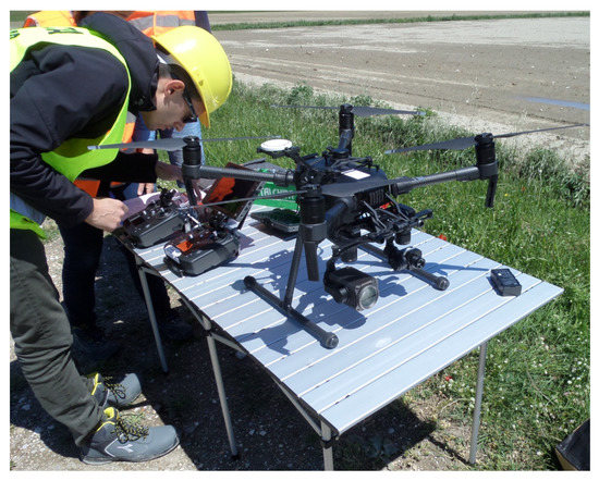
Figure 1.
The UAV and payload selected for the AWL project is shown: DJI Matrice 210 with thermal and optical sensor.
One of the unique characteristics that influenced the decision to use this platform is the ability to combine the use of two gimbals with two different types of sensors (for the AWL project, optical and thermal). In this scenario, a multi-sensor survey with simultaneous acquisition performed in the same flight during a constrained time window was tested.
FLIR radiometric Uncooled VOx microbolometer (DJI Zenmuse XT) with a pixel pitch of 17 μm, one spectral band ranging from 7.5 to 13.5 μm, and high acquisition speed at 30 Hz was chosen as the thermal sensor. The output image size is 640 × 512 pixels and the focal length is 13 mm, covering a Field of View (FOV) of 56°.
Since the primary role in this survey was played by the thermal sensor, a simpler 1/2.8 CMOS sensor element was used for the optical survey, such as the IMX291 (DJI Zenmuse Z30) with a pixel pitch of 2.9 μm and an output image size of 1920 × 1080 pixels that covers a FOV of 64°. For some of the monitoring sessions in the middle of the project activities, there was also the opportunity to acquire optical images by means of an auxiliary flight with FC220 camera (DJI Mavic Pro) with pixel size 1.6 μm, image size of 4000 × 3000 pixels and a focal length of 4.73 mm that covers a FOV of 79°.
2.2. Case Study
The research area is in the Emilia-Romagna region in Northern Italy, between the Reno and Lamone rivers’ outlets, on the Adriatic coastline (Figure 2). The crop fields are located about 2500 m west of the Adriatic coast, and the Reno river’s man-made embankment borders them on the north. Dirt roads split the fields into various land parcels. The fields’ average elevation is less than 0.5 m above mean sea level (AMSL). Furthermore, a significant land subsidence process has historically had an impact on the surveyed coastal region. The Emilia-Romagna plain is prone to subsidence, a phenomenon with varied proportions of anthropogenic and natural causes depending on the location [35]. In 1999, a significant leveling network was used to launch the first regional monitoring effort. The monitoring strategy in following years has principally been centered on modern integrated spatial geodesy and remote sensing techniques. The subsidence of the case study area is estimated to be roughly 2.5 mm/year by a recent interferometric data analysis study [36]. Land subsidence, when coupled with sea level rise, greatly raises the exposure of coastal areas to flood risk and encourages saltwater intrusion into the shallow coastal aquifer, seriously compromising the fertility and productivity of agricultural soils [37].
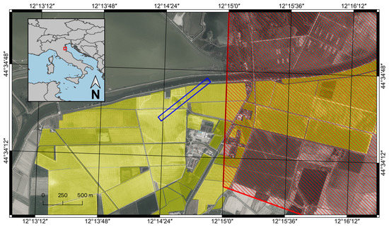
Figure 2.
The location of the case study. The UAV corridor is delimited by the blue boundary. Polygons of the fields of Agrisfera are highlighted in yellow with NFZ highlighted in red. Orthophoto AGEA 2011 is provided by Regione Emilia-Romagna Geoportal and used as the basemap.
The case study involves some cultivated fields of Agrisfera Società Cooperativa Agricola, which were selected as a pilot for the AWL project, in the province of Ravenna (Italy) between Casal Borsetti and Mandriole villages. The initial step in the planning process was to determine the research area that would have been surveyed. For project activities, the area of interest for sampling was to be five hectares. To ensure that considerable areas of cultivated plots were covered, a specific elongated geometry was established so as to map a wide corridor (Figure 2), comprising a section of maize field (north-east) and a section of soybean field (south-west). In fact, for the same size of the area surveyed, a long and narrow geometry allowed more crop fields to be observed. Operations in areas further east were inhibited, due to a No-Flight Zone (NFZ) enforced along the coastline; such restrictions will be covered and discussed in more detail in Section 5.
The survey area identified in this way and set as a polygon on the flight plan has a total size of 800 m in length and 64 m in width for a total of 5.12 hectares.
2.3. Ground Data
While flight operations were underway, some ground data that would be helpful for survey calibration were also collected. In fact, in the context of the AWL project, agrometeorological stations and systems for surveying soil and groundwater properties were installed nearby, obtaining the average data of air temperature and humidity.
Additionally, during the entire time of the overflight operations, ground temperature data were collected over the overflown area using a specialized logger connected to a thermocouple (type K) and programmed to acquire a temperature reading every five minutes. The thermocouple was fixed by a high-resistance transparent adhesive tape to the center of a white plastic panel with an indicative size of 2 m2. This target is clearly visible from the thermal images. Furthermore, a highly reflective panel of the same size and some smaller reflective targets were used for the purposes of image calibration, as detailed in the following Section 3.2 and Section 3.1, respectively.
3. Methods
3.1. Mission Flight Planning
To ensure efficient and thorough development of scientific results, UAV flight missions were planned in an attempt to find the optimal trade-off between the best practices described in the literature [8], the local regulations, and the specific requirements of the application. In particular, the proper flight altitude, flight direction, and design of a repeatable flight in a multi-temporal context were addressed, complying with the restrictions in place on flight activities.
There are multiple applications for Mission Flight Planning for UAVs [38] but, in order to have a complete analytical planning performed a priori, we opted for a specific technical solution with ground station software [39,40,41] and performed the planned flight with the Litchi (VC Technology Ltd, London, UK, Android version 4.13.0) mobile application. In fact, mobile applications for flight planning typically have fewer features than ground station software [8].
In order to minimize any temperature differences due to short-term changes in environmental conditions or due to drift issues with thermal sensors in adjacent images, the flight plan is based on survey lines transverse to the maximum length of the area (Figure 3). Thanks to this method, images of geometrically near regions could be acquired in a smaller time window compared to a typical longitudinal flight, optimizing the description of temperatures of contiguous areas and reducing discontinuities. Additionally, it was planned to reduce the flight speed of the UAV to hovering condition at each shooting location, to reduce any image blur, especially for the thermal sensor characterized by a slow acquisition time.
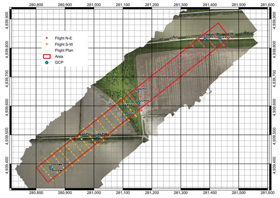
Figure 3.
Flight planning taking into account the described restrictions and constraints. Grid coordinates are ETRS89/UTM zone 33N (EPSG:25833). The RGB orthomosaic was obtained from the first experimental survey.
The placement of Ground Control Points (GCPs), which could be semi-permanent and thus available for all the survey dates, required careful planning as well. The geometry of the crop fields in this case study forced the selection of some GCPs, as is frequently the case in PA applications. Consequently, it was necessary to install a limited number of GCPs at certain structures, such as the concrete foundation of an irrigation system and the edges of farm vehicle maneuvering roads, in locations outside the fields that needed to be surveyed (Figure 3). The placement of some GCPs was not ideal given the circumstances and given the reduced number of points used, it was not possible to derive a subset as independent checkpoints. It has been demonstrated, however, that adding GCPs to the overflown block center does not significantly improve the planimetric accuracy of the processed surveys [42]. A GNSS receiver was used to measure the coordinates of every GCP with Network Real-Time Kinematic (NRTK) positioning technique, with about 0.02 m precision.
To locate GCPs that might be regarded as permanent for the full period of the survey activities, wooden pegs of approximately 0.4 m and squared section were partially driven into the ground to materialize on the surface the benchmarks for the georeferencing of the different overflights. Furthermore, specially constructed 0.3 × 0.3 m removable targets were created with a hole in the center of the same dimensions of the peg section, to ensure a forced centering. To make the targets clearly visible and identifiable in both optical and thermal pictures, aluminum foil was glued on the surface (Figure 4).
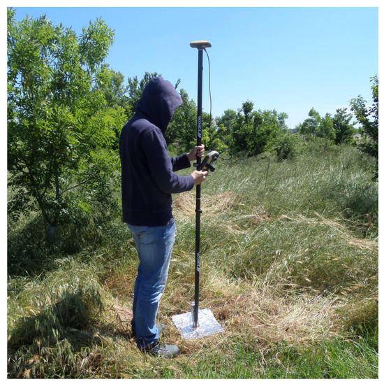
Figure 4.
GNSS survey for a 0.3 × 0.3 m GCP, in an area beside the cultivated fields.
Based on the designated area, UAV flights were scheduled in accordance with the internal parameters of the thermal sensor, guaranteeing coverage of the entire study area with an overlap between adjacent frames of 80% longitudinal and 65% transversal. The selected percentage was a good compromise between the ideal overlap and the required flight time to complete the survey [43]. In this case study, all the processing was performed later at an office, therefore, the amount of imagery and its impact on data processing timelines were not considered issues. More refined balancing of the number of images acquired to enable faster processing is undoubtedly crucial in some real-time processing contexts [44].
Given the size of the area and the amount of time needed to fly over it, the flight plan was divided evenly into two portions, each of which covering an equal amount of ground (Figure 3): northeast and southwest. Targets and GCPs present in the area of operations properly constrained each of these two blocks geometrically. Given the UAV autonomy, the flight activities entailed taking off and surveying the first northeast block, landing to change batteries, taking off again to survey the second block, and returning to the takeoff location and finally landing to complete the mission.
To ensure that operations were performed in Visual Line Of Sight (VLOS) mode with the UAV always in line of sight and at a distance of less than 500 m from the pilot (according to local flight regulations), the takeoff and landing points, which coincided with the positions of the pilot and GCS, were purposefully planned in the center of the survey area, appropriately placed so as to not be included within the acquired frames. It should also be noted that the Reno River was flown over for a portion of the flight in the northeast because it served as a useful water surface temperature reference for the AWL project. This portion of the area was included in the first part of the flight plan for survey safety in order to approach it with fully charged UAV batteries, reducing the possibility of emergency landings on water.
Each planned flight has a duration of 20 min including takeoff, maneuvering between adjacent survey lines, Return To Home (RTH), and landing. Each flight empirically uses nearly 70% of the battery pack consisting of two high-capacity TB55 elements (7660 mAh each) for the DJI Matrice 210 UAV in the dual-sensor payload configuration.
The dates and times of the surveys were carefully selected to be coincident with LANDSAT-8 satellite passes [45] over the survey area, for the analyses performed for the AWL project in the related paper [34] and in the absence of cloud cover. The dates are the following:
- S01: May 16 (experimental, before sowing);
- S02: May 25 (experimental);
- S03: June 14 (experimental);
- S04: June 17 (experimental);
- S05: June 26 (production);
- S06: July 03 (production);
- S07: July 19 (production);
- S08: August 05 (production);
- S09: September 04 (production, after harvesting).
3.2. Thermal Image Pre-Processing
Temperature values recorded by the thermal camera are brightness temperatures and require a correction for the effects of the atmosphere and of the emissivity of the observed surfaces.
Regarding the atmosphere, the model implemented in the software ResearchIR (Teledyne FLIR LLC, Wilsonville, OR, USA, version 4.40) was used. The main parameters to be set are the distance between the sensor and the surface, the air temperature and the relative humidity at the time of acquisition. The first one was derived from the navigation data of the UAV (flight altitude), whilst the others were obtained from the recordings of the meteorological stations installed near the study area for the project.
The software also allows to compensate for the emissivity; however, the emissivity value changes with the land cover. The study area is mainly composed of maize crops and bare soils, for which the values of 0.98 and 0.95 were assigned, respectively.
Since real surfaces are not black bodies, the contribution of the energy coming from the surrounding environment and reflected toward the sensor should be evaluated. For this purpose, a highly reflective aluminum panel was placed on the ground. The emissivity of the aluminum is close to zero [46], so the signal coming from that surface is largely due to reflections of the energy emitted by surrounding objects and clear sky. Therefore, the brightness temperature measured over it was assumed as the “reflected temperature” for the FLIR model.
Finally, a white plastic panel with a contact thermocouple (type K as described in Section 2.3) was used to check the accuracy of the radiometric calibration. The emissivity of this material was carefully measured in the lab with the aid of a thermal camera and a contact probe and was determined to be 0.84–0.86. The temperature read from the image pixels over the panel was then compared to the recording of the thermocouple.
3.3. Image Processing
Images from the UAV platform, information about the targets on the ground, and sensor network data were all processed. This technical note focuses specifically on the UAV data collected.
As previously mentioned, radiometric thermal images underwent a pre-processing. This preliminary processing produces a series of Tag Image File Format (TIFF) images without Exchangeable image file (EXIF) information. The approximate GNSS coordinates associated with each frame acquisition position, which are useful for the first stage of SfM processing, are not transmitted in the absence of EXIF data. The coordinates of each initially acquired image were first exported to a CSV text file using the ExifTool (Phil Harvey, Version 11.77) software, together with the image file name. The CSV file was further manipulated to insert the precise overflight altitude according to the flight plan.
The images were, therefore, imported for SfM processing in the software Metashape Professional Edition (Agisoft LLC, St. Petersburg, Russia) version 1.8. The processing used the approximate coordinates of the shot centers from the previously prepared CSV (assigning to them an accuracy of 10 m, typical of UAV GNSS) and the coordinates of the GCPs (measured by NRTK technique with an accuracy of about 0.02 m) to constrain the bundle adjustment.
At this stage, all planimetric coordinates were contextually brought into a single design reference system, which was identified as ETRS89/UTM zone 33N (EPSG:25833). The elevations Above Ground Level (AGL) recorded in each EXIF were transformed into ellipsoid elevations by adding the ellipsoid ground elevation measured with GNSS NRTK, and finally into orthometric elevations by knowing in the study area the geoid height above the ellipsoid. As is the case in several study areas for PA, the surveyed area is particularly flat, with less than one meter elevation change detected by GNSS measurements carried out for GCPs.
By creating a sparse point cloud, the images were initially aligned. All outliers were manually eliminated. In each frame where they are visible, the centers of all GCPs with known coordinates were collimated. Tolerances and measurement errors were checked appropriately. As a result, the cameras’ alignment parameters were optimized, and the final model dense point cloud was created. On the point cloud, a mesh was created that serves as the foundation for the subsequent creation of orthomosaics (optical or thermal in the respective cases). A Digital Elevation Model (DEM), which is produced as part of the optical image processing, was also created (Figure 5).
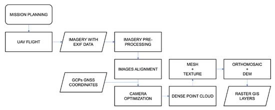
Figure 5.
Flowchart representing the complete UAV workflow. The first two steps specifically developed for this work are described in Section 4.2 and detailed in the checklist in Appendix A. The next steps implement SfM procedures.
To make the final map more uniform and readable and to reduce any effects of different illumination or exposure that may be present in adjacent frames, a blending procedure should be used when creating orthomosaics from optical images. However, to prevent altering the temperature value recorded in the original frames, the blending procedure was not used on thermal images. Due to the common drift issues with thermal sensors, it is possible to see radiometric jumps in pixels between various adjacent images. Finally, by placing a static bounding box over the studied area to enable GIS analysis on a pixel basis, the final raster plots were aligned with one another and for subsequent multi-temporal surveys. Additionally, in GIS, offset and gain values that were applied during preliminary thermal processing were reset to their original values.
4. Results
A multi-temporal experimental survey with multiple overflights was conducted on nine dates in the year 2019; the results are reported in this section. The first survey dates in the AWL project served as an experimental field test of the entire process (S01–S04), from flight planning, to refine the reference checklist and test data processing, before the sowing and growing phase. The middle dates (S05–S08) of the survey campaign were the most helpful for interpreting the acquired data for the AWL project, as discussed in the publication [34] in the comparison with satellite imagery. The last survey (S09) was performed after harvesting as a final benchmark. The processed flights were performed at an altitude of 95 m AGL according to the criteria described in Section 3.1.
The LST data of every survey are exported in raster format as an orthomosaic with a GSD of 0.05 m. Compared to the white plastic panel, all the thermal orthomosaics show a slight overestimation of the LST by 2.5 °C on average. The RGB optical data are exported as a raster orthomosaic with a GSD of 0.02 m. The DEM is also exported in raster format, with ground pixels having a size of 0.02 m. Figure 6 shows the processing of S07 and a detailed sampling on an area with dimensions m for all production dates.
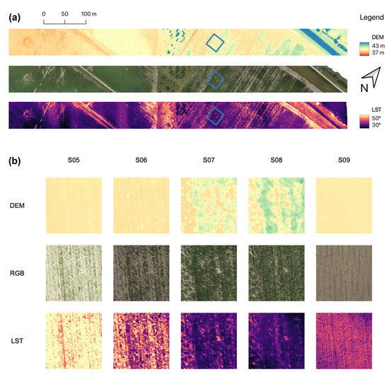
Figure 6.
Final processing results of the UAV surveys: from top to bottom the DEMs, the RGB mosaics and the LST mosaics. (a) The entire 5 ha survey area in the S07 survey; (b) A sample area (highlighted in (a) in blue) in all the production surveys (S05–S09).
4.1. Sfm Quality
The inner calibration parameters of the thermal camera are obtained through a self-calibration approach and each block adjustment results in a different set of values. It can be observed in Figure 7 that the solutions for thermal images are quite unstable compared to the solutions for visible cameras; for example, focal length values vary up to 20% for thermal cameras (while for Z30 RGB camera it is only 3%). Similar results are obtained for all the inner calibration parameters.
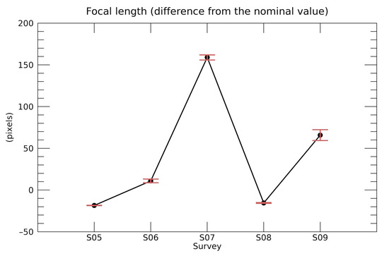
Figure 7.
Focal length deviation from the nominal value (in pixel units) computed for the different surveys in the self-calibration procedure.
The bundle adjustment strategy, however, is often able to “absorb” the uncertainty in the parameters. The reprojection errors are reported in Figure 8a and their magnitude is fully comparable to the corresponding values for the RGB camera.
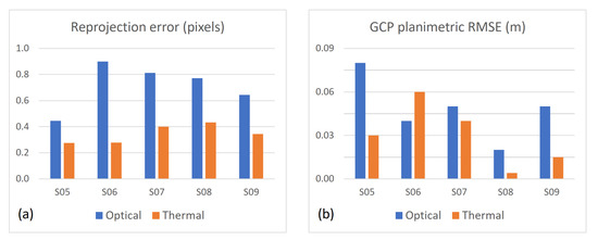
Figure 8.
Comparison between (a) the reprojection errors (in GSD units) and (b) GCP residuals in planimetry (in metres), computed for RGB and thermal images for all the surveys.
Some information about the quality of the SfM reconstruction can be derived by analyzing the dense point cloud generated from the thermal images, especially by comparing it with the one obtained from visible images. It is worthwhile to point out that the point density from thermal images is about 18 points/m2, while the corresponding average density from RGB images is 80 points/m2 with Z30 camera and even 950 points/m2 with FC220. In all the surveys, the two clouds (thermal and RGB) are obtained independently and they appear quite aligned overall: performing an Iterative Closest Point (ICP) procedure results in a negligible rotation and sub-pixel translations (the largest is 0.05 m along the Z direction). The results of the M3C2 (Multiscale model-to-model cloud comparison) distance [47] calculated without refining the alignment are showed in Figure 9 for the seventh survey (S7). On average, the distance along the vertical is 0.04 m Figure 10, but the standard deviation is 0.98 m. There are areas, especially in the south-west part, in which the thermal cloud is up to five meters higher than the visible one. These results confirm that the lower resolution and contrast of thermal images limit the accuracy of the reconstruction with a SfM approach.
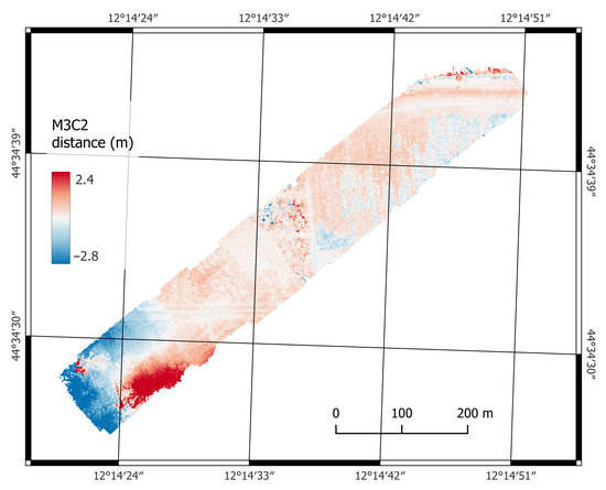
Figure 9.
M3C2 distance map between the point clouds generated by thermal and visible images, respectively, for S07 survey.
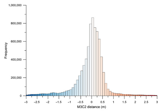
Figure 10.
Frequency distribution of the M3C2 values showed in the map of Figure 9.
The mentioned limitations in the reconstruction, however, do not significantly compromise the accuracy of the orthomosaic. Looking to the GCPs, the residuals in planimetry are fully comparable with the ones computed from RGB (Figure 8b). Additionally, the residuals along the vertical direction do not show meaningful differences.
4.2. UAV Survey Checklist
A UAV pre-flight checklist can help ensure legal and safe operation. UAV pilots may use this checklist to ensure everything is prepared before a UAV takes off, from crucial physical element verification to paperwork confirmation. UAV pre-flight checklists help reduce the possibility of physical property damage, injuries, and UAV damage during operations.
The checklist, which is implemented for the AWL project and is focused on surveys for PA, was originally developed by expanding each item based on field experience during the initial experimental flights and was also derived from information that other authors had described [8], considering the various critical issues and drawing on safety principles derived from aviation procedures. It consists of a sequence of six main sections that are in turn divided into a sequence of detailed operations. It is published in Appendix A as it might be helpful resource for UAV missions in the future, including ones that are not specifically related to PA. The first two phases are preliminary instruments check and mission planning, typically completed in the lab before leaving for the mission site. Launch site setup and UAS equipment check should be completed immediately before the flight. The final three phases (pre-flight, take-off, post-flight) are completed on the actual mission day at the survey site.
5. Discussion
The case study that was presented required several problems to be solved and the usage of unique arrangements in terms of geomatics and data calibration. For this reason, it has been particularly interesting to find workable solutions to problems with UAV flights for PA.
The execution of a single flyover with thermal and optical sensors within a constrained time window (corresponding to the LANDSAT-8 satellite overpass in the study area) was a specific requirement for the UAV survey described in this technical note to meet the goals described in Masina et al. [34]. Therefore, since the thermal camera has a smaller FOV than the optical one, it was necessary to set the flight plan by giving it priority. To ensure adequate coverage and overlap among thermal images, an excessive number of optical images were captured during the same flight, also because they are acquired on regular time-interval basis. In fact, 200 thermal images and between 400 and 500 optical images were acquired for each date. As a result, during optical image processing, it was necessary to manually select only the images that needed to be processed, removing excessively overlapping and unevenly distributed ones, even within the areas where the UAV needed to move from one survey line to the next. After choosing appropriate images, photogrammetric processing was always carried out automatically with only a small amount of manual assistance needed for GCP collimation.
In a multi-temporal experiment, it was necessary to place GCPs in secure locations that were regarded as permanent for all the scheduled working days. In fact, to ensure geometric correspondence between elaborations obtained in different survey epochs, it is important to maintain the same reference points. Alternately, every survey day would have required the placement and survey of new GCPs decreasing the reliability of the final result. In the case study detailed in this technical note, GCPs were materialized with wooden pegs in locations deemed stable away from the working areas of the cultivated fields, but despite this, for some GCPs, a new materialization and subsequent GNSS survey were required because they were unintentionally lost between two surveys. A common and important problem with PA surveys is the severe restrictions on target placement: targets, indeed, cannot be placed within cultivated areas, as they would be destroyed by the movement and maneuvering of farm vehicles. Additionally, it is common for cultivated areas to be completely void of landmarks or other forms of discontinuities that could serve as reference or tie points. Another peculiarity is that this multi-sensor project required special targets that could be visible in both the optical and thermal spectra. Adopting the specific SfM targets provided by the software (which would have been collimated automatically) was, therefore, not an option. Considering all the challenges mentioned, it was not possible to place a larger amount of GCPs and include additional measurements to be used as check points after the bundle adjustment. Independent check points, indeed, are required for a rigorous estimate of the metric quality of the mosaicked images, and their use is to be regarded as a good practice for SfM processing. However, in PA surveys, it is often difficult to establish enough points for a robust statistical analysis.
Modern direct georeferencing techniques for UAV platforms [48,49,50,51] can speed up survey operations, while still generating processed data with precise enough georeferencing for PA goals. These methods can be applied with minimal or no GCPs on the ground and light differential GNSS receivers mounted on UAVs. When using Real-Time Kinematic (RTK) or Post-Processing Kinematic (PPK) positioning, the captured image points are georeferenced with sufficient accuracy for PA applications.
Some distinctive characteristics of thermal images make the use of SfM algorithms more troublesome or, more often, a significant drop in their accuracy is observed [52,53]. Thermal images, in fact, present a lower dynamic range and geometric resolution when compared to the classic images in the visible wavelengths, together with poor definition of the discontinuities and small details (e.g., blurred edges), since digital number variations are related to surface temperature or emissivity differences [54]. The context of PA, where the analysis of differences detected on relative temperatures is considered more important than the absolute temperature value, should also be taken into consideration when discussing some decisions made regarding thermal image processing. For the same reason, the average discrepancy of 2.5 °C in LST (observed over the white plastic panel; see Section 4) can be considered acceptable for the proposed application. When necessary, the use of a more sophisticated model for sensor calibration and atmospheric correction may improve the absolute radiometric accuracy [55], especially for higher-altitude UAV surveys.
The flight speed that must be slowed down because of the longer exposure time of the image is another crucial issue with the use of thermal cameras in PA. Despite taking the necessary precautions during mosaicking in the SFM workflow, critical situations may still arise for the reasons mentioned above, as well as in our case study: low resolution, low contrast, and image blur due to high winds or gimbal issues. Some of these issues prevented the proper processing of the thermal images captured in S02-S03-S04. Additionally, alignment issues were experienced for the acquisition of optical images during the survey that was conducted in August (S08) due to correlation failures on the cultivated areas where the density of crops completely covered the ground. Tie points were manually added in some cases.
Frequent and widespread restrictions that are put in place in the airspace, such as NFZ [56], must be considered in mission planning to avoid entering prohibited areas [57]. For instance, these limits are in place in sensitive urban areas [58] or in controlled airspace near the coast [59], and although they are enforced to ensure the safety of airspace, they have a negative impact on the possibilities of land surveying using UAVs. In fact, a NFZ (LI R10—Foci del Reno) exists near the case study area, preventing overflight of cultivated areas farther east, close to the coastline (Figure 3).
National laws are being replaced by EU legislation for the use of UAVs. According to these laws, a UAV pilot will be permitted to operate UAVs in the EU after obtaining the necessary permission. The EU regulation will encompass all potential UAV activities, encouraging the creation of cutting-edge initiatives, such as PA [5].
For PA, it is interesting to consider the idea that an experiment such as the one presented in this work, which was conducted on a small area of 5 hectares with a rotary-wing UAV, is also technologically replicable on large areas by operating under BVLOS conditions [60]. Due to their longer endurance, fixed-wing UAVs are an especially practical option in this scenario and offer an efficient flight [3]. To ensure safe operations, however, operating in BVLOS necessitates protocols and compliance with strict requirements [61]. According to the literature reviewed for this technical note and experience gained in defining the platform used for the experiments conducted, fixed-wing UAVs are particularly useful in large-area surveying contexts to mitigate major operational costs, in particular for the platform, and greater logistical difficulties such as the use of ramps for takeoff and landing.
In previous years, numerous differences have been noted by some authors between different national legal systems [62]. The use of UAV technology and its economic potential in various application areas may be aided or hampered by some of these new regulations [63]. In fact, due to the widespread use of UAV technologies, regulatory organizations around the world are rushing to create effective frameworks to control their operation. The relevant certificates and authorization regulations are still being defined, even though from a technical perspective, UAV operations have already attained a level of maturity that permits safe operations in BVLOS and in automatic mode without direct pilot control. Assuming the use of a sufficiently capable UAS platform with an appropriate class identification, fully autonomous agricultural UAV operations will most likely be feasible soon. There are still some unknowns regarding the precise specifications for such a UAV and the classification approval procedure [6]. Regarding the certification of UAVs and their MTOW, it should be noted that new COTS models with more compact dimensions that can better meet the requirements of flight regulations have been introduced in the past year.
6. Conclusions
This technical note discussed the quality of the results that can be achieved with commercial off-the-shelf sensors and UAVs and provided an overview of possible future developments to increase the autonomy of these systems. A comprehensive description of the procedures followed to achieve the presented results was provided: from flight planning to data processing. The restitution of a detailed checklist for each step of the work was proposed as an operational method, which can identify a compromise solution among all the critical issues encountered. Technical problems related to flight planning and data processing were discussed by developing a procedure to achieve consistent results in a PA context, with numerous multi-sensor UAV overflights. The final accuracy of the products is in the range of 0.10 m on the geometric component, which is thought to be sufficient for PA applications considering the conditions of the investigated terrains and the survey parameters.
Author Contributions
Conceptualization, A.L. and E.M.; Methodology, A.L., M.A.T. and E.M.; Formal Analysis, A.L. and M.A.T.; Investigation, A.L. and M.A.T.; Data Curation, A.L.; Writing—Original Draft Preparation, A.L. and E.M.; Writing—Review and Editing, E.M. and L.V.; Visualization, A.L. and E.M.; Supervision, L.V.; Project Administration, L.V. All authors have read and agreed to the published version of the manuscript.
Funding
This research was funded by the LIFE 2014–2020 EU Programme, through LIFE AGROWETLANDS II–Smart Water and Soil Salinity Management in AGROWETLANDS Project (LIFE15 ENV/IT/000423).
Institutional Review Board Statement
Not applicable.
Informed Consent Statement
Not applicable.
Data Availability Statement
Not applicable.
Acknowledgments
The Authors acknowledge the support of Agrisfera Soc. Coop. Agr. p.a. for field management and Luca Poluzzi for the support in GCP field survey. The Authors would like to thank also the project leader of LIFE AGROWETLANDS II, Maria Speranza.
Conflicts of Interest
The authors declare no conflict of interest.
Abbreviations
The following abbreviations are used in this manuscript:
| AGL | Above Ground Level |
| AI | Artificial Intelligence |
| AMSL | Above Mean Sea Level |
| AWL | LIFE AGROWETLANDS II |
| BVLOS | Beyond Visual Line Of Sight |
| CC | Canopy Cover |
| COTS | Commercial Off-The-Shelf |
| DEM | Digital Elevation Model |
| DSM | Digital Surface Model |
| DSS | Decision Support System |
| EXIF | Exchangeable Image File |
| FOV | Field Of View |
| GCP | Ground Control Point |
| GCS | Ground Control Station |
| GIS | Geographic Information System |
| GNSS | Global Navigation Satellite System |
| GSD | Ground Sample Distance |
| EU | European Union |
| FFC | Flat Field Correction |
| ICP | Iterative Closest Point |
| IMU | Inertial Measurement Unit |
| LiDAR | Light Detection And Ranging |
| LST | Land Surface Temperature |
| MTOW | Maximum Take-Off Weight |
| NRTK | Network Real-Time Kinematic |
| NOTAM | Notice To Airmen |
| NFZ | No-Flight Zone |
| PA | Precision Agriculture |
| PPE | Personal Protective Equipment |
| RGB | Red, Green, Blue |
| RPAS | Remotely Piloted Aerial Systems |
| RTH | Return To Home |
| RTK | Real-time Kinematic |
| SLAM | Simultaneous Localization And Mapping |
| SfM | Structure from Motion |
| TIFF | Tag Image File Format |
| UA | Unmanned Aircraft |
| UAS | Unmanned Aircraft System |
| UAV | Unmanned Aerial Vehicle |
| VLOS | Visual Line Of Sight |
| VPS | Vision Positioning System |
| VTOL | Vertical Take-Off and Landing |
| WSN | Wireless Sensor Network |
Appendix A. Checklist
This is the checklist for all the surveying operations implemented in the AWL project. It is described in Section 4.2.
- 1.
- PRELIMINARY INSTRUMENTS CHECK:
- 1.1
- Verify installation and capacity of storage media for each sensor;
- 1.2
- Recharge all batteries in the UAV and GCS;
- 1.3
- Checking availability of any firmware and software updates;
- 1.4
- Preparation of spare materials for UAV such as propellers, tools, etc.;
- 1.5
- Preparation of survey support instruments: GNSS receivers, thermocouples, etc.;
- 1.6
- Preparation of targets for GCP and related supports;
- 1.7
- Verification of necessary documentation for UAV flight: permits, insurance, pilot training, etc.;
- 1.8
- Verification of safety equipment and Personal Protective Equipment (PPE).
- 2.
- PRELIMINARY MISSION PLANNING:
- 2.1
- Definition of survey area and photogrammetric flight planning;
- 2.2
- Verification of weather forecast, wind and its impact on UAV range;
- 2.3
- Verification of Notice to Airmen (NOTAM) and NFZ;
- 2.4
- Verification of local authorizations for the area to be flown over and access to the mission area.
- 3.
- LAUNCH SITE SETUP:
- 3.1
- Verification of the take-off and landing area;
- 3.2
- Verification of any physical obstacles or electromagnetic interference in the survey area;
- 3.3
- Arrangement of GCPs within the area to be surveyed;
- 3.4
- GNSS survey of the position of each GCP;
- 3.5
- Setting thermocouples on target for thermal survey.
- 4.
- UAS EQUIPMENT CHECK:
- 4.1
- Verification of tablet–radio connection;
- 4.2
- Verification of correct gimbal movement of each sensor;
- 4.3
- UAV inspection and verification: propeller tightening, any damage to the structure, motors, compass, GNSS, Inertial Measurement Unit (IMU) and Vision Positioning System (VPS), and related electronic connections;
- 4.4
- Battery insertion;
- 4.5
- Memory media insertion;
- 4.6
- Sensor connection (for DJI Matrice 210: Pos1 for thermal sensor and Pos2 for optical sensor);
- 4.7
- Put on PPE;
- 4.8
- Setting flight plan on tablet–radio control;
- 4.9
- Checking radio control mode setting;
- 4.10
- Setting flight planner (Litchi);
- 4.11
- Check radio control antenna position;
- 4.12
- Turn on radio control.
- 5.
- PRE-FLIGHT:
- 5.1
- Synchronization of takeoff time with satellite passage;
- 5.2
- “GeoFence” setting for flight limits: maximum flight altitude and maximum distance
- 5.3
- Battery threshold level settings;
- 5.4
- UAV power on;
- 5.5
- Compass calibration (it may be convienent to perform it before mounting the sensors with the gimbals);
- 5.6
- IMU and VPS calibration check;
- 5.7
- Thermal camera parameter setup (Zenmuse XT): saving RJPEG radiometric images and preparing for Flat Field Correction (FFC) calibration;
- 5.8
- Optical camera parameter setup: white balance, shutter speed, aperture, interval shooting;
- 5.9
- Gimbal motion synchronization of the two cameras set nadiral;
- 5.10
- UAV positioning on take-off point;
- 5.11
- UAV stays on a few minutes to let sensors reach operating temperature;
- 5.12
- RTH point setting;
- 5.13
- Radio control signal verification;
- 5.14
- GNSS signal verification;
- 5.15
- Battery check: charge, temperature, UAV, and GCS voltage;
- 5.16
- Flight mode verification: for DJI Matrice 210 setting P (Positioning);
- 5.17
- Zenmuse XT thermal camera calibration: FFC on the ground before takeoff using an aluminum cover with uniform temperature to cover the camera’s field of view as directed by the manufacturer;
- 5.18
- Removal of lens cover and verification of lens cleanliness of each sensor.
- 6.
- TAKE-OFF:
- 6.1
- UAV LED status signal check;
- 6.2
- Propeller installation;
- 6.3
- Verify launch site clear for take off;
- 6.4
- Record takeoff time;
- 6.5
- Start engines;
- 6.6
- Manual takeoff and verify stable hovering;
- 6.7
- Verify command response;
- 6.8
- Planned flight start;
- 6.9
- Nadiral sensor check;
- 6.10
- Secondary optical camera setup with interval shooting.
- 7.
- POST-FLIGHT:
- 7.1
- Landing at end of mission;
- 7.2
- Landing time recording;
- 7.3
- Stop optical camera interval shot;
- 7.4
- Repeat FFC procedure for thermal camera calibration;
- 7.5
- Power OFF UAV;
- 7.6
- Power OFF GCS;
- 7.7
- Extracting memory media and making backup copy of acquired data;
- 7.8
- Recording flight data on logbook;
- 7.9
- Battery change when necessary to perform a second flight;
- 7.10
- Target and sensor recovery at end of mission.
References
- Sishodia, R.P.; Ray, R.L.; Singh, S.K. Applications of remote sensing in precision agriculture: A review. Remote Sens. 2020, 12, 3136. [Google Scholar] [CrossRef]
- Colomina, I.; Molina, P. Unmanned aerial systems for photogrammetry and remote sensing: A review. ISPRS J. Photogramm. Remote Sens. 2014, 92, 79–97. [Google Scholar] [CrossRef]
- Delavarpour, N.; Koparan, C.; Nowatzki, J.; Bajwa, S.; Sun, X. A technical study on UAV characteristics for precision agriculture applications and associated practical challenges. Remote Sens. 2021, 13, 1204. [Google Scholar] [CrossRef]
- Mogili, U.R.; Deepak, B.B. Review on Application of Drone Systems in Precision Agriculture. Procedia Comput. Sci. 2018, 133, 502–509. [Google Scholar] [CrossRef]
- Tsouros, D.C.; Bibi, S.; Sarigiannidis, P.G. A review on UAV-based applications for precision agriculture. Information 2019, 10, 349. [Google Scholar] [CrossRef]
- Merz, M.; Pedro, D.; Skliros, V.; Bergenhem, C.; Himanka, M.; Houge, T.; Matos-Carvalho, J.P.; Lundkvist, H.; Cürüklü, B.; Hamrén, R.; et al. Autonomous UAS-Based Agriculture Applications: General Overview and Relevant European Case Studies. Drones 2022, 6, 128. [Google Scholar] [CrossRef]
- Aguilar, F.J.; Rivas, J.R.; Nemmaoui, A.; Peñalver, A.; Aguilar, M.A. UAV-based digital terrain model generation under leaf-off conditions to support teak plantations inventories in tropical dry forests. A case of the coastal region of Ecuador. Sensors 2019, 19, 1934. [Google Scholar] [CrossRef]
- Tmušić, G.; Manfreda, S.; Aasen, H.; James, M.R.; Gonçalves, G.; Ben-Dor, E.; Brook, A.; Polinova, M.; Arranz, J.J.; Mészáros, J.; et al. Current practices in UAS-based environmental monitoring. Remote Sens. 2020, 12, 1001. [Google Scholar] [CrossRef]
- Yao, H.; Qin, R.; Chen, X. Unmanned aerial vehicle for remote sensing applications—A review. Remote Sens. 2019, 11, 1443. [Google Scholar] [CrossRef]
- Chen, W.; Liu, J.; Guo, H.; Kato, N. Toward Robust and Intelligent Drone Swarm: Challenges and Future Directions. IEEE Netw. 2020, 34, 278–283. [Google Scholar] [CrossRef]
- Gago, J.; Estrany, J.; Estes, L.; Fernie, A.R.; Alorda, B.; Brotman, Y.; Flexas, J.; Escalona, J.M.; Medrano, H. Nano and Micro Unmanned Aerial Vehicles (UAVs): A New Grand Challenge for Precision Agriculture? Curr. Protoc. Plant Biol. 2020, 5, e20103. [Google Scholar] [CrossRef] [PubMed]
- Aslan, M.F.; Durdu, A.; Sabanci, K.; Ropelewska, E.; Gültekin, S.S. A Comprehensive Survey of the Recent Studies with UAV for Precision Agriculture in Open Fields and Greenhouses. Appl. Sci. 2022, 12, 1047. [Google Scholar] [CrossRef]
- Nex, F.; Armenakis, C.; Cramer, M.; Cucci, D.A.; Gerke, M.; Honkavaara, E.; Kukko, A.; Persello, C.; Skaloud, J. UAV in the advent of the twenties: Where we stand and what is next. ISPRS J. Photogramm. Remote Sens. 2022, 184, 215–242. [Google Scholar] [CrossRef]
- Liu, J.; Xiang, J.; Jin, Y.; Liu, R.; Yan, J.; Wang, L. Boost precision agriculture with unmanned aerial vehicle remote sensing and edge intelligence: A survey. Remote Sens. 2021, 13, 4387. [Google Scholar] [CrossRef]
- Deng, L.; Mao, Z.; Li, X.; Hu, Z.; Duan, F.; Yan, Y. UAV-based multispectral remote sensing for precision agriculture: A comparison between different cameras. ISPRS J. Photogramm. Remote Sens. 2018, 146, 124–136. [Google Scholar] [CrossRef]
- Adão, T.; Hruška, J.; Pádua, L.; Bessa, J.; Peres, E.; Morais, R.; Sousa, J.J. Hyperspectral imaging: A review on UAV-based sensors, data processing and applications for agriculture and forestry. Remote Sens. 2017, 9, 1110. [Google Scholar] [CrossRef]
- Messina, G.; Modica, G. Applications of UAV thermal imagery in precision agriculture: State of the art and future research outlook. Remote Sens. 2020, 12, 1491. [Google Scholar] [CrossRef]
- Rincón, M.G.; Mendez, D.; Colorado, J.D. Four-Dimensional Plant Phenotyping Model Integrating Low-Density LiDAR Data and Multispectral Images. Remote Sens. 2022, 14, 356. [Google Scholar] [CrossRef]
- Inoue, Y.; Yokoyama, M. Drone-Based Optical, Thermal, and 3d Sensing for Diagnostic Information in Smart Farming—Systems and Algorithms. In Proceedings of the International Geoscience and Remote Sensing Symposium (IGARSS), Yokohama, Japan, 28 July–2 August 2019; pp. 7266–7269. [Google Scholar] [CrossRef]
- Donati, C.; Mammarella, M.; Comba, L.; Biglia, A.; Gay, P.; Dabbene, F. 3D Distance Filter for the Autonomous Navigation of UAVs in Agricultural Scenarios. Remote Sens. 2022, 14, 1374. [Google Scholar] [CrossRef]
- Pagliai, A.; Ammoniaci, M.; Sarri, D.; Lisci, R.; Perria, R.; Vieri, M.; D’arcangelo, E.; Storchi, P.; Kartsiotis, S.P. Comparison of Aerial and Ground 3D Point Clouds for Canopy Size Assessment in Precision Viticulture. Remote Sens. 2022, 14, 1145. [Google Scholar] [CrossRef]
- Mazzia, V.; Comba, L.; Khaliq, A.; Chiaberge, M.; Gay, P. UAV and machine learning based refinement of a satellite-driven vegetation index for precision agriculture. Sensors 2020, 20, 2530. [Google Scholar] [CrossRef] [PubMed]
- Khanal, S.; Fulton, J.; Shearer, S. An overview of current and potential applications of thermal remote sensing in precision agriculture. Comput. Electron. Agric. 2017, 139, 22–32. [Google Scholar] [CrossRef]
- Santesteban, L.G.; Di Gennaro, S.F.; Herrero-Langreo, A.; Miranda, C.; Royo, J.B.; Matese, A. High-resolution UAV-based thermal imaging to estimate the instantaneous and seasonal variability of plant water status within a vineyard. Agric. Water Manag. 2017, 183, 49–59. [Google Scholar] [CrossRef]
- López, A.; Jurado, J.M.; Ogayar, C.J.; Feito, F.R. An optimized approach for generating dense thermal point clouds from UAV-imagery. ISPRS J. Photogramm. Remote Sens. 2021, 182, 78–95. [Google Scholar] [CrossRef]
- Javadnejad, F.; Gillins, D.T.; Parrish, C.E.; Slocum, R.K. A photogrammetric approach to fusing natural colour and thermal infrared UAS imagery in 3D point cloud generation. Int. J. Remote Sens. 2020, 41, 211–237. [Google Scholar] [CrossRef]
- Iizuka, K.; Watanabe, K.; Kato, T.; Putri, N.A.; Silsigia, S.; Kameoka, T.; Kozan, O. Visualizing the spatiotemporal trends of thermal characteristics in a peatland plantation forest in Indonesia: Pilot test using unmanned aerial systems (UASs). Remote Sens. 2018, 10, 1345. [Google Scholar] [CrossRef]
- AGROWETLANDS. AGROWETLANDS II Project Funded by LIFE 2014–2020 European Union Programme. Available online: http://www.lifeagrowetlands2.eu/ (accessed on 31 August 2022).
- Calone, R.; Sanoubar, R.; Lambertini, C.; Speranza, M.; Vittori Antisari, L.; Vianello, G.; Barbanti, L. Salt tolerance and na allocation in sorghum bicolor under variable soil and water salinity. Plants 2020, 9, 561. [Google Scholar] [CrossRef]
- Cipolla, S.S.; Maglionico, M.; Masina, M.; Lamberti, A.; Daprà, I. Real Time Monitoring of Water Quality in an Agricultural Area with Salinity Problems. Environ. Eng. Manag. J. 2019, 18, 2229–2240. [Google Scholar]
- Vittori Antisari, L.; Speranza, M.; Ferronato, C.; De Feudis, M.; Vianello, G.; Falsone, G. Assessment of water quality and soil salinity in the agricultural coastal plain Ravenna, North Italy. Minerals 2020, 10, 369. [Google Scholar] [CrossRef]
- Masina, M.; Calone, R.; Barbanti, L.; Mazzotti, C.; Lamberti, A.; Speranza, M. Smart water and soil-salinity management in agro-wetlands. Environ. Eng. Manag. J. 2019, 18, 2273–2285. [Google Scholar]
- De Feudis, M.; Falsone, G.; Gherardi, M.; Speranza, M.; Vianello, G.; Vittori Antisari, L. GIS-based soil maps as tools to evaluate land capability and suitability in a coastal reclaimed area (Ravenna, northern Italy). Int. Soil Water Conserv. Res. 2021, 9, 167–179. [Google Scholar] [CrossRef]
- Masina, M.; Lambertini, A.; Daprà, I.; Mandanici, E.; Lamberti, A. Remote Sensing Analysis of Surface Temperature from Heterogeneous Data in a Maize Field and Related Water Stress. Remote Sens. 2020, 12, 2506. [Google Scholar] [CrossRef]
- Bitelli, G.; Bonsignore, F.; Pellegrino, I.; Vittuari, L. Evolution of the techniques for subsidence monitoring at regional scale: The case of Emilia-Romagna region (Italy). Proc. Int. Assoc. Hydrol. Sci. 2015, 372, 315–321. [Google Scholar] [CrossRef]
- Bitelli, G.; Bonsignore, F.; Del Conte, S.; Franci, F.; Lambertini, A.; Novali, F.; Severi, P.; Vittuari, L. Updating the subsidence map of Emilia-Romagna region (Italy) by integration of SAR interferometry and GNSS time series: The 2011–2016 period. Proc. Int. Assoc. Hydrol. Sci. 2020, 382, 39–44. [Google Scholar] [CrossRef]
- Antonellini, M.; Mollema, P.; Giambastiani, B.; Bishop, K.; Caruso, L.; Minchio, A.; Pellegrini, L.; Sabia, M.; Ulazzi, E.; Gabbianelli, G. Salt water intrusion in the coastal aquifer of the southern Po Plain, Italy. Hydrogeol. J. 2008, 16, 1541–1556. [Google Scholar] [CrossRef]
- Gómez-López, J.M.; Pérez-García, J.L.; Mozas-Calvache, A.T.; Delgado-García, J. Mission flight planning of rpas for photogrammetric studies in complex scenes. ISPRS Int. J. Geo-Inf. 2020, 9, 392. [Google Scholar] [CrossRef]
- AeroScientific. DJIFlightPlanner. Available online: https://www.djiflightplanner.com/ (accessed on 31 August 2022).
- Roth, L.; Hund, A.; Aasen, H. PhenoFly Planning Tool: Flight planning for high-resolution optical remote sensing with unmanned areal systems. Plant Methods 2018, 14, 116. [Google Scholar] [CrossRef]
- Team, A.D. ArduPilot Mission Planner. Available online: https://ardupilot.org/planner/ (accessed on 31 August 2022).
- Rangel, J.M.G.; Gonçalves, G.R.; Pérez, J.A. The impact of number and spatial distribution of GCPs on the positional accuracy of geospatial products derived from low-cost UASs. Int. J. Remote Sens. 2018, 39, 7154–7171. [Google Scholar] [CrossRef]
- Lopes Bento, N.; Araújo E Silva Ferraz, G.; Alexandre Pena Barata, R.; Santos Santana, L.; Diennevan Souza Barbosa, B.; Conti, L.; Becciolini, V.; Rossi, G. Overlap influence in images obtained by an unmanned aerial vehicle on a digital terrain model of altimetric precision. Eur. J. Remote Sens. 2022, 55, 263–276. [Google Scholar] [CrossRef]
- Deng, J.; Zhong, Z.; Huang, H.; Lan, Y.; Han, Y.; Zhang, Y. Lightweight semantic segmentation network for real-time weed mapping using unmanned aerial vehicles. Appl. Sci. 2020, 10, 7132. [Google Scholar] [CrossRef]
- Satellite Data Services. Polar Orbit Tracks. Available online: https://www.ssec.wisc.edu/datacenter/ (accessed on 31 August 2022).
- Kuenzer, C.; Dech, S. Theoretical Background of Thermal Infrared Remote Sensing. In Thermal Infrared Remote Sensing: Sensors, Methods, Applications; Kuenzer, C., Dech, S., Eds.; Springer: Dordrecht, The Netherlands, 2013; pp. 1–26. [Google Scholar] [CrossRef]
- James, M.R.; Robson, S.; Smith, M.W. 3-D uncertainty-based topographic change detection with structure-from-motion photogrammetry: Precision maps for ground control and directly georeferenced surveys. Earth Surf. Process. Landforms 2017, 42, 1769–1788. [Google Scholar] [CrossRef]
- Mian, O.; Lutes, J.; Lipa, G.; Hutton, J.J.; Gavelle, E.; Borghini, S. Direct georeferencing on small unmanned aerial platforms for improved reliability and accuracy of mapping without the need for ground control points. Int. Arch. Photogramm. Remote. Sens. Spat. Inf. Sci.-ISPRS Arch. 2015, 40, 397–402. [Google Scholar] [CrossRef]
- Turner, D.; Lucieer, A.; Wallace, L. Direct georeferencing of ultrahigh-resolution UAV imagery. IEEE Trans. Geosci. Remote Sens. 2014, 52, 2738–2745. [Google Scholar] [CrossRef]
- Chiabrando, F.; Giulio Tonolo, F.; Lingua, A. Uav direct georeferencing approach in an emergency mapping context. the 2016 central Italy earthquake case study. Int. Arch. Photogramm. Remote. Sens. Spat. Inf. Sci.-ISPRS Arch. 2019, 42, 247–253. [Google Scholar] [CrossRef]
- Syetiawan, A.; Gularso, H.; Kusnadi, G.I.; Pramudita, G.N. Precise topographic mapping using direct georeferencing in UAV. IOP Conf. Ser.: Earth Environ. Sci 2020, 500, 012029. [Google Scholar] [CrossRef]
- Khodaei, B.; Samadzadegan, F.; Javan, F.D.; Hasani, H. 3D surface generation from aerial thermal imagery. Int. Arch. Photogramm. Remote. Sens. Spat. Inf. Sci.-ISPRS Arch. 2015, 40, 401–405. [Google Scholar] [CrossRef]
- Maes, W.H.; Huete, A.R.; Steppe, K. Optimizing the processing of UAV-based thermal imagery. Remote Sens. 2017, 9, 476. [Google Scholar] [CrossRef]
- Conte, P.; Girelli, V.A.; Mandanici, E. Structure from Motion for aerial thermal imagery at city scale: Pre-processing, camera calibration, accuracy assessment. ISPRS J. Photogramm. Remote Sens. 2018, 146, 320–333. [Google Scholar] [CrossRef]
- Ribeiro-Gomes, K.; Hernández-López, D.; Ortega, J.F.; Ballesteros, R.; Poblete, T.; Moreno, M.A. Uncooled Thermal Camera Calibration and Optimization of the Photogrammetry Process for UAV Applications in Agriculture. Sensors 2017, 17, 2173. [Google Scholar] [CrossRef]
- Alarcón, V.; García, M.; Alarcón, F.; Viguria, A.; Martínez, A.; Janisch, D.; Acevedo, J.J.; Maza, I.; Ollero, A. Procedures for the Integration of Drones into the Airspace Based on U-Space Services. Aerospace 2020, 7, 128. [Google Scholar] [CrossRef]
- Ramirez-Atencia, C.; Camacho, D. Extending QGroundControl for Automated Mission Planning of UAVs. Sensors 2018, 18, 2339. [Google Scholar] [CrossRef] [PubMed]
- Trevisiol, F.; Lambertini, A.; Franci, F.; Mandanici, E. An Object-Oriented Approach to the Classification of Roofing Materials Using Very High-Resolution Satellite Stereo-Pairs. Remote Sens. 2022, 14, 849. [Google Scholar] [CrossRef]
- Turner, I.L.; Harley, M.D.; Drummond, C.D. UAVs for coastal surveying. Coast. Eng. 2016, 114, 19–24. [Google Scholar] [CrossRef]
- Hartley, R.J.a.L.; Henderson, I.L.; Jackson, C.L. BVLOS Unmanned Aircraft Operations in Forest Environments. Drones 2022, 6, 167. [Google Scholar] [CrossRef]
- Fang, S.X.; O’young, S.; Rolland, L. Development of small UAS beyond-visual-line-of-sight (BVLOS) flight operations: System requirements and procedures. Drones 2018, 2, 13. [Google Scholar] [CrossRef]
- Tsiamis, N.; Efthymiou, L.; Tsagarakis, K.P. A comparative analysis of the legislation evolution for drone use in oecd countries. Drones 2019, 3, 75. [Google Scholar] [CrossRef]
- Alamouri, A.; Lampert, A.; Gerke, M. An exploratory investigation of UAS regulations in europe and the impact on effective use and economic potential. Drones 2021, 5, 63. [Google Scholar] [CrossRef]
Publisher’s Note: MDPI stays neutral with regard to jurisdictional claims in published maps and institutional affiliations. |
© 2022 by the authors. Licensee MDPI, Basel, Switzerland. This article is an open access article distributed under the terms and conditions of the Creative Commons Attribution (CC BY) license (https://creativecommons.org/licenses/by/4.0/).