Article

Composite Electromagnetic Scattering and High-Resolution SAR Imaging of Multiple Targets above Rough Surface

1
Air Defense and Antimissile School, Air Force Engineering University, Xi’an 710051, China
2
National Laboratory of Radar Signal Processing, Xidian University, Xi’an 710071, China
*
Author to whom correspondence should be addressed.
Remote Sens. 2022, 14(12), 2910; https://doi.org/10.3390/rs14122910
Submission received: 23 May 2022 / Revised: 12 June 2022 / Accepted: 14 June 2022 / Published: 17 June 2022
(This article belongs to the Special Issue Small or Moving Target Detection with Advanced Radar System)

Abstract

:
Aiming at the high efficiency of composite electromagnetic scattering analysis and radar target detection and recognition utilizing high-range resolution profile (HRRP) characteristics and high-resolution synthetic aperture radar (SAR) images, a near-field modified iterative physical optics and facet-based two-scale model for analysis of composite electromagnetic scattering from multiple targets above rough surface have been presented. In this method, the coupling scattering of multiple targets is calculated by near-field iterative physical optics and the far-field scattering is calculated by the physical optics method. For the evaluation of the scattering of an electrically large sea surface, a slope cutoff probability distribution function is introduced in the two-scale model. Moreover, a fast imaging method is introduced based on the proposed hybrid electromagnetic scattering method. The numerical results show the effectiveness of the proposed method, which can generate backscattering data accurately and obtain high-resolution SAR images. It is concluded that the proposed method has the advantages of accurate computation and good recognition performance.

Graphical Abstract

1. Introduction

In recent years, the composite electromagnetic (EM) scattering characteristics of perfect electrical conductor (PEC) target above dielectric rough surface has been widely researched, which is important in target detection, target recognition, remote sensing, stealth designation, etc. [1]. Meanwhile, SAR imaging which is mainly applied to radar target identification and classification is a hotspot in the military application domain [2] and plays an essential role in air defense and anti-missile. However, the analysis of composite EM scattering and SAR imaging characteristics of multiple electrically large targets above the sea surface has not been sufficiently researched or drawn scientific conclusions.
Lots of research has been conducted in the field of EM scattering computation and SAR imaging. Utilizing the commercial EM simulator, the raw SAR data is generated based on a point target model [3]. An accelerated algorithm based on geometrical optics, physical optics and physical theory of diffraction is proposed to improve the computation efficiency of composite scattering and SAR imaging simulation from an electrically large target. [4,5]. Similarly, an approach using the ray perspective and SAR imaging algorithms for simulation of the SAR image of the tank corresponding to Multi-Bounce scattering is presented [6]. An advanced multiple input and multiple output SAR algorithm for 3-D SAR imaging is presented. Additionally, acceleration strategies have been introduced to parallelize the simulation [7]. A SAR imaging simulation method for time-varying sea surface is presented, which is helpful to better understand SAR images of ocean waves [8]. In [9], an improved Kirchhoff approximation, shooting bouncing ray and geometrical theory of diffraction are employed to calculate the total scattered field collected by SAR in synthetic aperture. It presents a new EM model for evaluating the radar multipath scattering and observes the multipath influence on radar HRRP characteristics of a low-altitude target which is valuable for target detection and remote sensing [10]. Combining the EM scattering calculation model and the method of radar echo signal simulation, an efficient method has been proposed to analyze the scattering and SAR imaging from objects [1].
Most of the SAR image simulations are focused on the target in the free space. However, for the simulation of SAR images from the sea surface in remote sensing, an improved facet-based two-scale model is proposed which combines the integral equation method and Kirchhoff approximation [11]. A feasible hybrid EM scheme combining physical optics and Bragg Modified Small Scale Approximation method and geometrical optics has been developed to evaluate the composite scattering and the SAR image characteristic of a low altitude PEC target [12]. The physical optics and shooting bouncing ray method are combined to rapidly compute the EM scattering from a ship on a sea surface; therefore, it can generate massive backscatter data for SAR imaging [13]. In addition, the SAR image simulations are conducted based on a facet scattering model considering the multipath coupling mechanisms between the ultra-low altitude targets and the sea surface [14]. Similarly, a weighted multi-path model is presented to analyze the composite EM scattering and SAR image of the sea surface with a ship target [15]. Based on the multi-path EM scattering model, a scattering signatures modeling method for bistatic imaging radar is proposed [16]. Moreover, the method can be applied for the simulation of echo signals and SAR imaging.
As for the detection method, based on the information theory and Harris corner detection for SAR images, a ship target detection method is proposed [17]. Exploiting a segmentation-based morphological performance algorithm, a ship detection scheme for SAR images is established [18]. A 3-D propagation model based on the uniform theory of diffraction and ray-tracing method is proposed, which can be applied to synthesize data for SAR image evaluation [2]. Based on the shooting bouncing ray method and improved bidirectional ray-tracing algorithm, the large-angle and wide-bandwidth scattering data are obtained. Then, by conducting SAR imaging processing, the high-resolution SAR images can be produced [19]. In order to generate the SAR echo data efficiently and accurately, the shooting bouncing ray and physical optics hybrid method are employed for EM scattering prediction of electrically larger targets. Therefore, based on the proposed SAR simulator above, the polarimetric features extraction and analysis of military targets can be conducted. As for target detection and tracking in the underwater environment and on the sea surface, several types of research have been conducted in recent years. Based on empirical analysis, a novel approach for autonomous surface vehicle detection on the sea surface is presented. Additionally, it can be utilized for anti-collision systems development [20]. Similarly, to overcome the inherent accuracies of navigational sensors, multi-sensor data fusion algorithms are developed, which improve the reliability of position prediction for unmanned surface vehicle operation [21]. In order to achieve online object tracking, an adaptive Spatio-temporal context-based algorithm is proposed, which can be applied in multiple scenarios [22]. Based on forward-looking-sonar images and Gaussian particle filter, an online processing and tracking approach is presented to resolve persistent multiple targets tracking in underwater environments [23]. However, while these methods can be applied for target detection and tracking in an underwater environment and on the sea surface, they are not applicable for the detection of ultra-low altitude military targets.
However, the aforementioned method ignores multiple scattering effects between the target and rough surface and the coupling effects among multiple targets. This article established a hybrid method combing Modified near-field iterative physical optics (IPO) and facet-based two-scale mode to analyze the composite EM scattering from multiple targets in the free space and above the rough sea surface. Moreover, based on the proposed method, the scattered echoes of the targets can be obtained, then the 1-dimensional distance image and SAR images can be obtained through the fast Fourier transform.
The rest of the paper is organized as follows: A near-field modified IPO method has been introduced for the scattering of multiple targets, and the principle of HRRP and fast SAR imaging method is described in detail in Section 2. Then, in Section 3, the EM scattering from multiple missile-like targets in the free space and above the rough sea surface is calculated, moreover, the efficiency and accuracy of the proposed EM scattering method are verified. In Section 4, the simulations of SAR images based on the proposed approach are presented and analyzed. At last, Section 5 provides the conclusion.

2. Methods

In general, the proposed method composes near-field IPO, a two-scale model, the principle of HRRP, and a fast SAR imaging method which will be described in detail in the following part.

2.1. Near-Field IPO

According to the magnetic field integral equation on the surface, the induced current can be written as
J = 2 n ^ × H i n c ( r ) + 2 n ^ × L ( M ) + 2 n ^ × K ( J )
where
L ( M ) = j ω ε 0 S [ M ( r ) G ( r , r ) + 1 k 2 M ( r ) G ( r , r ) ] d s
K ( J ) = S J ( r ) × G ( r , r ) d s
where H inc ( r ) is the incident magnetic field, S denotes the illuminated area on the dielectric rough surface. J (   r   ) and M (   r   ) represent the electric current and magnetic current on S , respectively. G ( r ,   r   ) is the Green function in the free space, k 0 is the wavenumbers in free space. Based on the impedance boundary condition
M ( r ) = Z s J ( r ) × n ^ .
The electric current J can be rewritten as
J = 2 n ^ × H i n c ( r ) + 2 Z s n ^ × L ( J ( r ) × n ^ ) + 2 n ^ × K ( J )
Therefore, the induced electric current on the facet i is given by
J i = 2 n ^ i × H i n c ( r ) + 2 Z s n ^ i × L ( J i ( r ) × n ^ i ) + 2 n ^ i × K ( J i )
Furthermore, considering the mutual effect of each facet on the rough surface, the Jacobi iteration method is utilized to update the electric current on the facet i , for i = 1 , 2 , , N the surface currents can be expressed as
J i ( k + 1 ) = 2 n ^ i × H i n c ( r ) + 2 j = 1 , j i N n ^ i × [ L ( J i ( k ) × n ^ i ) + 2 n ^ i × K ( J i ( k ) ) ] .
Under the condition of far-field, the Green function can be approximated by
G ( r , r ) = e x p ( j k | r r | ) 4 π | r r | e x p ( j k r ^ ( r r ) ) 4 π r .
However, as the targets are electrically large and near to each other, the Fraunhofer distance is not satisfied. Therefore, an expansion center r n lies in the neighborhood of the source point is introduced to modify the Green function in the near-field [24].
| r r | = | r r n r + r n | = | ( r r n ) ( r r n ) | .
And the modified Green function for near-field scattering can be given as
G = e x p ( j k | r r | ) 4 π | r r | e x p ( j k γ ^ n ( r r ) ) 4 π | γ ^ n | .
By substituting (6) into (5), the electric current J i ( k + 1 ) on the facet i , can be exactly evaluated. Therefore, based on the Stratton-Chu integral equation, the far-field EM scattering of multiple targets can be obtained. The integral equation can be solved by Gordon method.
In the facet-based model, the sea surface is generated by the Monte Carlo method combined with the Pierson and Moskowitz (PM) sea spectrum [25] which is shown as follows:
W P M = α p 2 k 3 exp ( β g 2 v 19.5 4 k 2 )
where α p = 8.1 × 10 - 3 , β = 0.74 denote the dimensionless empirical constant. g = 9.81   m / s 2 is the gravity acceleration, v 19.5 represent the wind speed at the height of 19.5   m above the sea surface. k is the wavenumber in the free space and k 2 = k x 2 + k y 2 in Cartesian coordinates.
Then the surface is discretized into small triangular patches. The total normalized radar cross section can be expressed as
σ p q = ν ( θ i , θ s ) S i = 1 M j = 1 N [ σ i j G O + σ i j S S A Δ x Δ y ]
where S denotes the illuminated area on the dielectric rough surface. ν ( θ i , θ s ) is the visibility factor, M and N represent the number of facets along x and y axis, respectively. The size of each patch is Δ x × Δ y . The GO can be expressed as
σ p q G O = i = 1 M i = 1 N π k i 2 q i j 2 q i j 4 | U p q , i j | 2 P L ( z x , z y )
where P L ( z x , z y ) denotes the slope probability density distribution of each facet [26]. The small-slope approximation (SSA) can be given as
σ S S A = 4 π | B q z | L ( Q , n ^ )
The integral over facet L ( Q , n ^ ) can be obtained by
L ( Q , n ^ ) = 1 4 π e x p ( Q n 1 h s 2 ) ʃ 0 [ e x p ( i Q r ) ( Q n 2 C ( r ) 1 ) ] d r .
Therefore, the facet-based model is expressed as follows:
σ p q = ν ( θ i , θ s ) S i = 1 M j = 1 N [ σ i j G O e x p ( q 2 h s 2 ) ( 1 e x p ( q z 2 h L 2 ) ) + σ i j S S A ] Δ x Δ y .

2.2. The Principle of HRRP

When the EM waves emitted by the radar irradiate a certain target, an induced current will be generated on the surface, resulting in scattering EM waves. Meanwhile, the scattering EM wave is generated by the modulation of the target surface, and the modulation process is determined by its structure. Therefore, the scattering distribution of the target can reflect its geometric structure characteristics. Because the HRRP can reflect the physical structure of the target and is relatively simple in imaging processing, it is widely used in the field of radar target recognition.
HRRP is the projection vector sum of the target scattering point echoes acquired by radar along the direction of radar line-of-sight (LOS). The scattering echo obtained by radar can be written as
S ( f ) = r e c t ( f f 0 B ) σ ( x , y ) e 2 j k R d x d y
where f is the frequency of the transmitted signal, f 0 denotes the center frequency. B represents the bandwidth, and k is wavenumber in the free space. R is the distance between the target and radar antenna. σ ( x , y ) denotes the scattering distribution function calculated by the EM scattering method. The HRRP image (Figure 1) is the projection of the two-dimensional scattering distribution on the radar LOS, which can be expressed as
σ ( R ) = l σ ( x , y ) d x d y
Then, the one-dimension range profile can be obtained by
s ( r ) = σ ( R ) sin c ( π B r c )
With the appearance of the scattering points, the distance image will fluctuate with different intensities, which is the distribution of the scattering center of the target in the distance direction.

2.3. SAR Imaging

It is of great significance in military Automatic Target Recognition (ATR) to generate images using SAR simulation. However, most SAR images for military ATR are not released for public use. Conventional high-resolution radar imaging is obtained by inverse Fourier transform (IFFT) of echo signal in a certain bandwidth and a range of angles, which makes it difficult to obtain the radar image of electrically large targets above the large rough surface.
In this section, a facet-based SAR imaging method is proposed. The transmitted radar signal is a linear modulated frequency (LMF) signal and is assumed to be of the form in Equation (20) below in the simulation
s ( t ) = A 0 w r ( t T ) exp ( j 2 π f c t + j π K r t 2 )
where A 0 denotes the amplitude of the signal, w r (   ) is a rectangular function that represents the pulse duration as a function of quick time, f c is the carrier frequency, K r presents the chirp rate, and t denotes the range time or quick time. After demodulation, the baseband signal of single-point target can be expressed as
s r ( t , t a ) = A 0 w r ( t 2 R ( t a ) / c ) exp [ j 2 π k r ( t 2 R ( t a ) / c ) 2 ] w a ( t a t c ) exp [ j 4 π R ( t a ) / λ ]
h ( t , t a ) = w r ( t 2 R ( t a ) / c ) w a ( t a t c ) exp [ j 4 π R ( t a ) / λ ] exp [ j π k r ( t 2 R ( t a ) / c ) 2 ]
where 2 R ( t a ) / c is the time delay, w a (   ) is the azimuth beam pattern amplitude modification. t a is the azimuth time and t c is the time of zero Doppler or azimuth time at which the center of the beam pattern crosses the center target area.
In order to establish the general model of the received signal, the scattering intensity of the rough sea surface and the impulse response are convoluted in two dimensions to obtain the baseband SAR signal data.
s b b ( t , t a ) = σ ( t , t a ) h ( t , t a ) + n ( t , t a )
where n ( t , t a ) presents the additive white Gaussian noise.
By coherent superposition of the scattered echo of each facet, which is calculated by the EM scattering method in the frequency domain, the total echo signal of the target is obtained by
s r ( t , t a ) = i = 1 N σ i ( t , t a ) w r ( t 2 R ( t a ) / c T ) exp [ j π k r ( t 2 R ( t a ) / c ) 2 ] exp [ j 4 π R ( t a ) / λ ] = w r ( t ) exp ( j π k r t 2 ) i = 1 N σ i ( t , t a ) exp [ j 4 π R ( t a ) / λ ] δ ( t 2 R ( t a ) / c )
where σ i ( t , t a ) denotes the scattering coefficient of the facet i , N presents the total number of the facet, δ (   ) is the impulse response function. Therefore, the frequency domain form can be obtained by the Fourier transform of the echo signal along the range direction.
s r ( f ) = i = 1 N σ i ( f , t a ) w r ( f ) B k r exp [ j π f 2 k r + j π 4 ] exp [ j 4 π f R i / c ] exp [ j 4 π f R i / λ ] = w r ( f ) B k r exp [ j π f 2 k r + j π 4 ] i = 1 N σ i ( f , t a ) exp [ j 4 π f R i / c ] = S ( f ) i = 1 N σ i ( f , t a ) exp [ j 4 π f R i / c ]
where σ i ( f , t a ) denotes the scattering coefficient of the facet i in the frequency domain. After obtaining the echo in the frequency domain, the echo signal of the time-domain form can be obtained by inverse Fourier transform.
s r ( t , t a ) = I F T [ S ( f ) E s ( f ) ]
From the raw signal, then the high-resolution SAR images can be simulated via usual SAR processing utilizing the Range-Doppler method.
An airborne stripe mode SAR system is shown in Figure 2, the radar is moving along the y -axis at a speed of v . θ i is the squint angle, and R represents the slant range.

3. Numerical Results

In this section, simulations are conducted to verify the feasibility and validity of the suggested hybrid method.

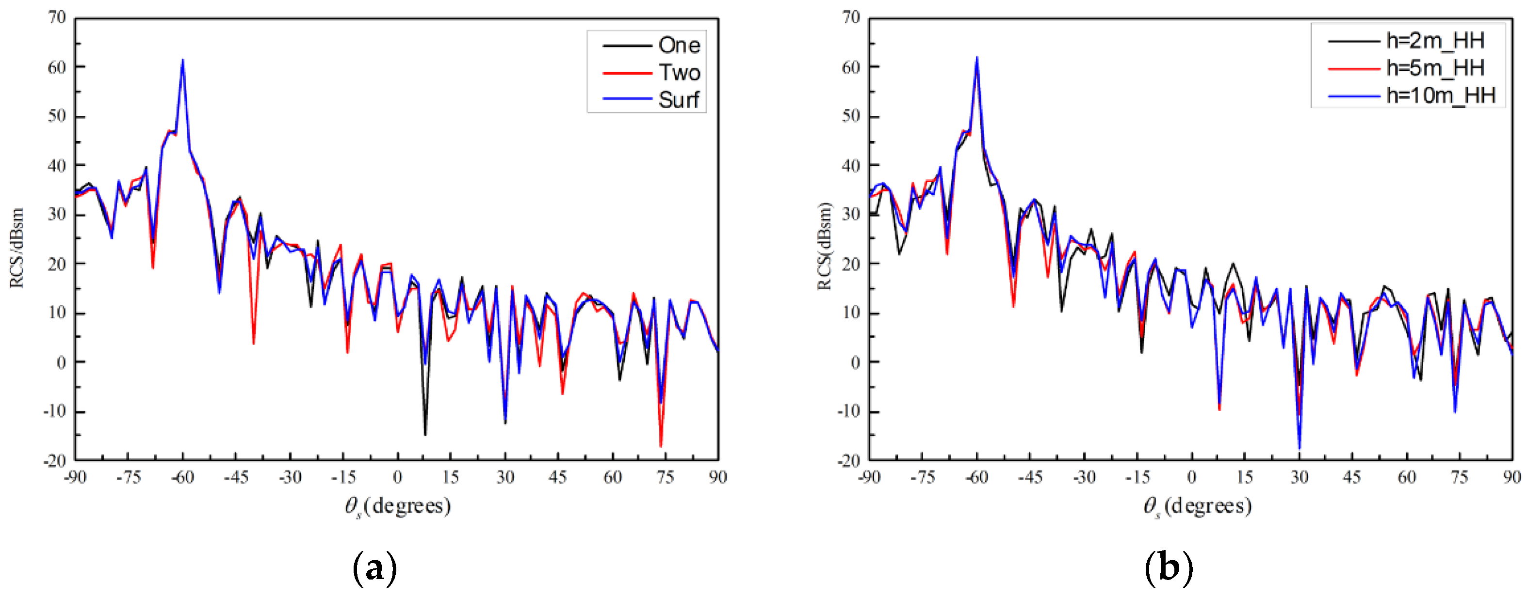
3.1. EM Scattering of Multiple Targets
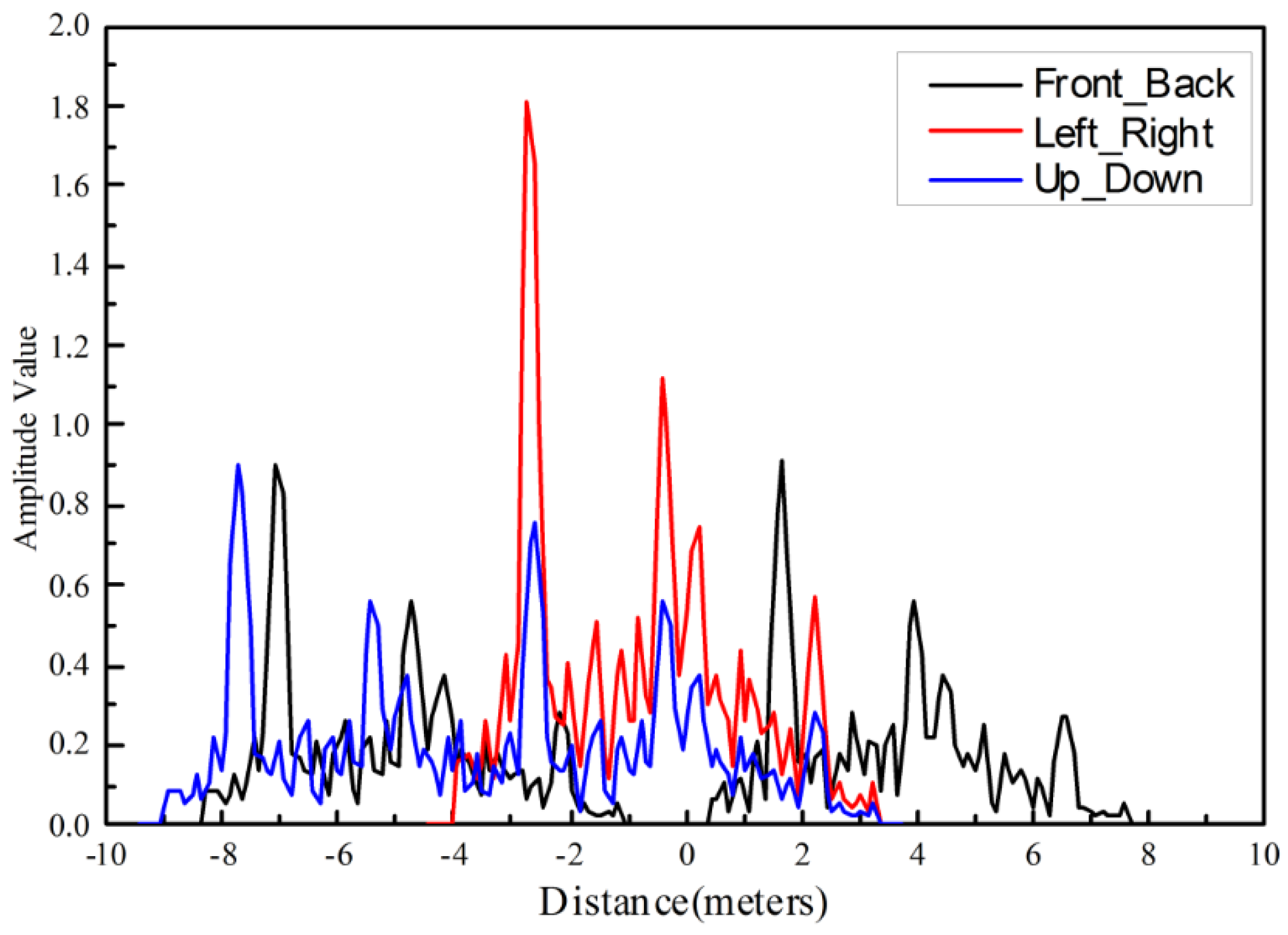
To verify the efficiency and accuracy of the proposed EM scattering method, in this section, the analysis of EM scattering from multiple missile-like targets in the free space as well as above the rough sea surface has been studied. The missile-like targets are located parallel to the positive x-axis and the distance between the two targets is 6 m. The length of the target is 5.2   m and the width of it is 2.4   m . The incident wave is at 1 GHz with the incident angle θ i ranges from 90 ° to 90 ° at azimuth angle φ i = 0 ° . The monostatic RCS is calculated as shown in Figure 3.
As shown in Figure 3, a good agreement has been achieved between the proposed hybrid method and MLFMM solver in commercial software FEKO. Meanwhile, compared with the RL-GO solver in FEKO, the result is more accurate when θ s 40 ° and θ s 30 ° . The root mean squared error (RMSE) between the results calculated by the proposed method and RL-GO solver and MLFMM solver is given in Table 1. The RMSE of the proposed method is much smaller than of the RL-GO solver, which means the proposed method is more accurate than the RL-GO solver in commercial software. Although it reduces CPU running time compared with the MLFMM solver, it is much larger than the RL-GO solver based on high-frequency approximation algorithm. It can be concluded that the proposed method has qualities in improving the accuracy of the high-frequency method and reducing the CPU time.
In the following simulation, the composite EM scattering from two missile-like targets above the electrically large rough sea surface is analyzed. The sea surface is generated by the Monte Carlo method combined with the Pierson and Moskowitz (PM) sea spectrum. The size of the surface is 30   m × 30   m , and the wind speed at 19.5   m high above the sea surface is 1   m / s . The incident angle are θ i = 60 ° and azimuth angle φ i = 0 ° . The simulation results are compared with that from MLFMM solver in FEKO. Figure 4 shows the bistatic scattering from two missile-like targets above the electrically large rough sea surface. It can be seen that the results from the proposed method agree well with the results from the MLFMM solver in FEKO in most ranges of the scattering directions. However, the error gets larger with the increase of the scattering angle.
The comparison of results from different numbers of targets has been presented in the previous works. For different polarizations, the scattering coefficient becomes larger with the increase of the target number [27]. However, it will be difficult to detect and identify multiple targets through the EM scattering characteristic, especially when the number of targets is the same but the location distribution is different. Figure 5 shows the location distribution of two missile-like targets.
Figure 6 shows the monostatic scattering coefficient of two PEC missile-like targets in the HH, HV, VH, and VV polarization. It can be seen in Figure 6 that, the difference in scattering coefficients is not obvious with the different location distribution, which brings great difficulty to target identification. Simultaneously, the EM scattering coefficient changes slightly with a different number of targets above the rough sea surface, which shows the results are insensitive to the number of targets. Figure 7a gives the bistatic scattering from the electrically large rough sea surface without or with one, or two missile-like targets above it. This result can be explained as follows: the EM scattering from the 3-dimensional rough surface is much stronger than that from the targets and the mutual interaction among different targets and rough surface.
Figure 7b presents the bistatic scattering results from two missile-like targets above the electrically large rough sea surface at the heights of 2   m , 5   m and 10   m . It can be seen that as the target height increases, the coupling scattering between the target and the rough sea surface decreased, however, the numerical change is not obvious. The aforementioned examples not only prove the accuracy of the algorithm, but also analyze the shortcomings of EM scattering analysis and problems faced in the target detection and recognition field.

3.2. HRRP Analysis

The location distribution of two missile-like targets have been shown in Figure 5. Utilizing the proposed IPO and two-scale model method to obtain the echo of the targets, then the 1-dimensional distance image can be obtained through a fast Fourier transform. The incident angle is θ i = 60 ° and the azimuth angle is φ i = 0 ° . It can be seen in Figure 8 that the length of the target is about 4.8   m (in radar LOS), and there are three main scatter centers that correspond to three main parts of the target including the nose-corn, wings, and empennage. When the two missile-like targets are at the same height above the rough sea surface and parallel to each other, the distance in radar LOS is the same; therefore, the scatter centers are in the same position, but the amplitude value increases.
When the targets are at the same height above the rough sea surface and in a tandem array, there are two repeated image sequences; meanwhile, the distance between two targets is about 8.8   m (in radar LOS). In addition, there are two repeated image sequences while the second is smaller when the targets are at a different height above the rough sea surface and parallel to each other. This is because the lower target is occluded by the upper one in the radar LOS. From the HRRP, the number of targets, the target projection length and the intensity of scattering can be obtained, which can improve the performance of target recognition.

4. SAR Imaging Simulation

In the following examples, based on the numerical analysis of EM scattering from multiple targets, the SAR images in the free space and above the rough sea surface are simulated. Moreover, the SAR images of different numbers of targets, different location distributions and different types of targets are given in part 1. As for the targets above a complicated sea environment, the SAR images of different numbers of targets and rotation angles are presented in part 2. Then, the simulation results are analyzed in detail.

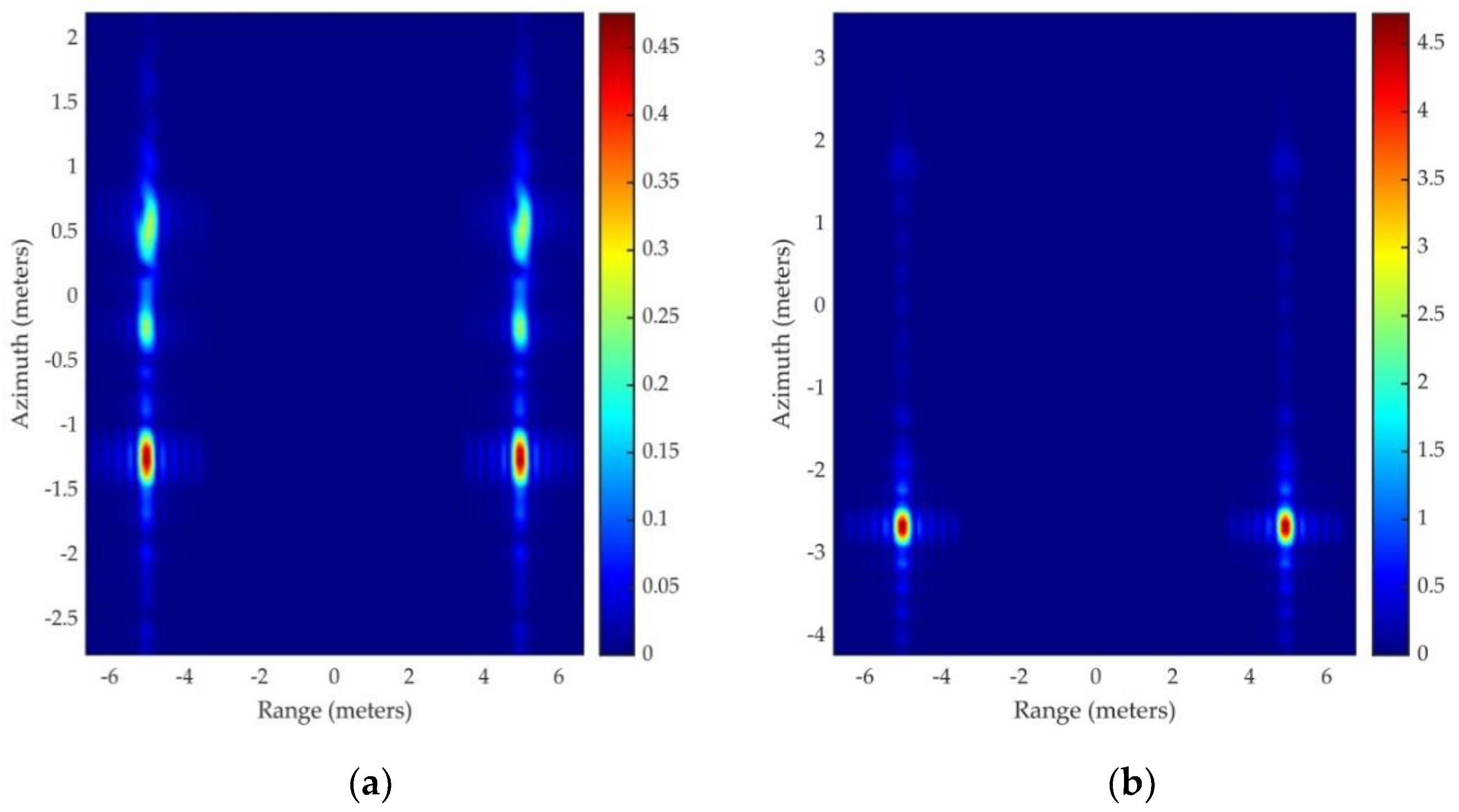
4.1. Targets in the Free Space

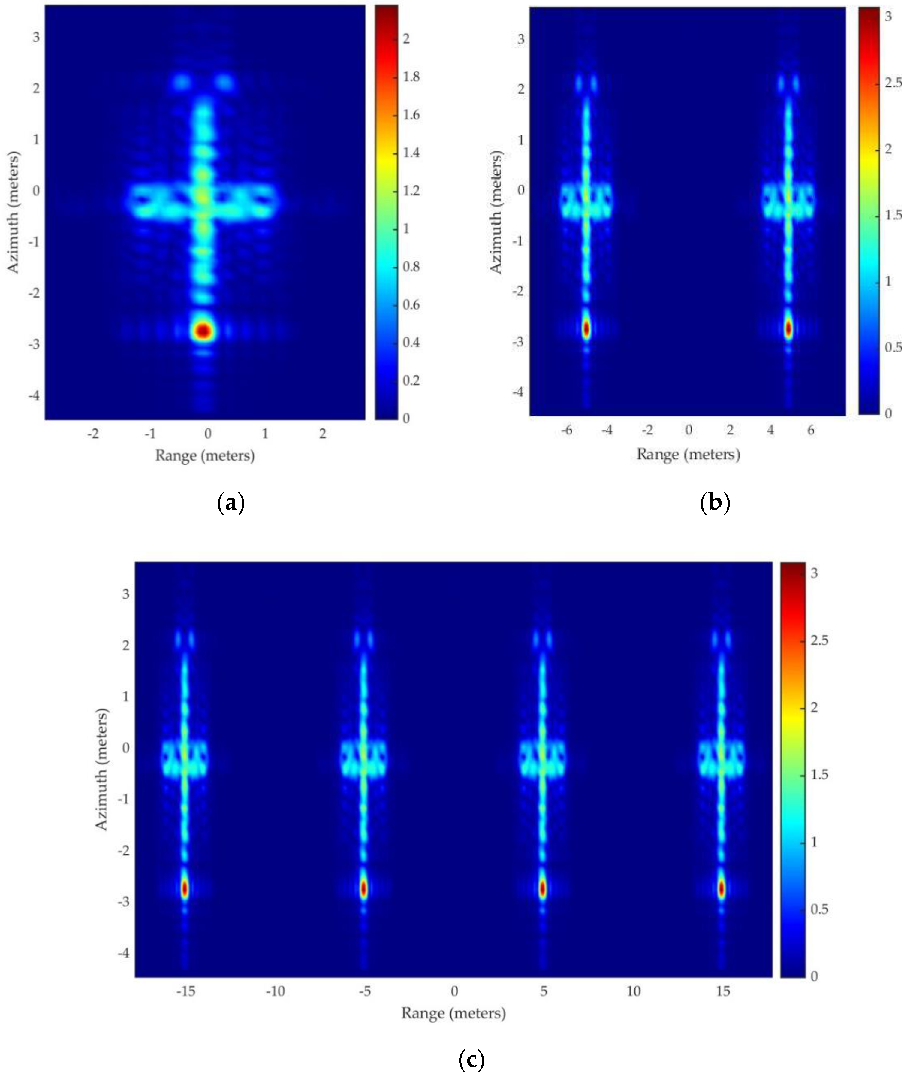
4.1.1. SAR Images of Different Number of Targets

In order to analyze the effects of the different target numbers on SAR imaging, the distribution of RCS and SAR images with different targets of 1, 2, and 4 are simulated. The incident angles are θ i = 60 ° and azimuth angle φ i = 0 ° , and the observation angles are θ s = 60 ° and azimuth angle φ i = 0 ° .
Figure 9 shows the SAR images of missile-like targets with a different number in the free space. It can be seen that the nose-corn, wings and empennage are the main scatter center of the target. Moreover, the scattering intensity of the nose-corn part is larger than the other part when the detection radar illuminates the target from the front. It indicates that the RCS reduction of the nose-corn part is vital for the stealth design. In addition, as the number of targets increases, the coupling effect has been strengthened, and the peak value increases. As can be seen, the missile-like target can be identified in Figure 9, and the number of it can be estimated accurately.

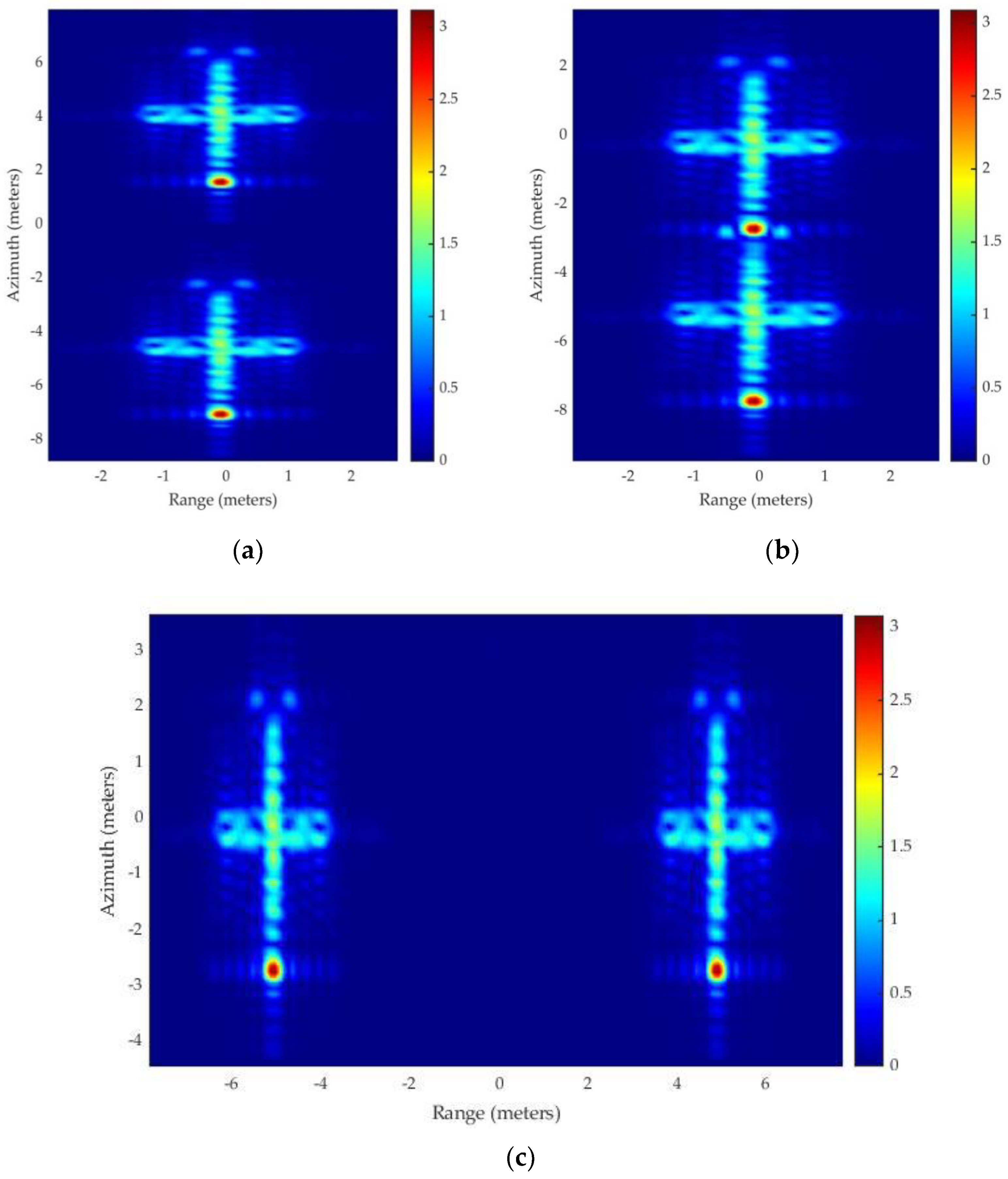
4.1.2. SAR Images of Different Location Distribution

When the number of targets is the same but the location distribution is different, it will be difficult to detect and identify multiple targets by analyzing the EM scattering characteristic in different polarizations. The location distribution of two missile-like targets have been shown in Figure 5. In order to analyze the effects of the different location distributions on SAR imaging, the SAR images are simulated.
As shown in Figure 10, there is no difference in scattering intensity between the three types of location distribution. However, the target image can be identified, which can be applied to detect and recognize the targets. Meanwhile, the projection distance between two targets can be obtained. In Figure 10 b, the images have overlapping parts, because the upper target occludes the other one in the radar LOS, which is similar to the results in the HRRP analysis part. However, through the analysis of Figure 10a,b, it is unable to distinguish the missile-like targets in the free space, whether they are at the same height in a tandem array or at a different height parallel to each other. In order to distinguish the position relationship better, it needs to be analyzed in combination with the 3-D imaging results in the future research.

4.1.3. SAR Images of Different Types of Targets

The geometries of different targets are shown in Figure 11. The size of the targets in Figure 11a–c are 2.09   m × 0.38   m , 4.63   m × 0.62   m and 8.60   m × 1.88   m , respectively. The comparison of SAR images from different types of targets is presented in Figure 12.
It can be seen from Figure 12 that the projections lengths of the targets in radar LOS are 1.80   m , 4.00   m and 7.50   m , respectively. Meanwhile, the nose-corn, wings and empennage are the main scatter center of the target. However, due to the different geometric structures and sizes of the targets, the peak scattering intensities values are different. Based on the projection length and the scattering intensities, the target can be clearly identified. Therefore, it can be widely applied in target recognition, image classification, scene matching and so forth.

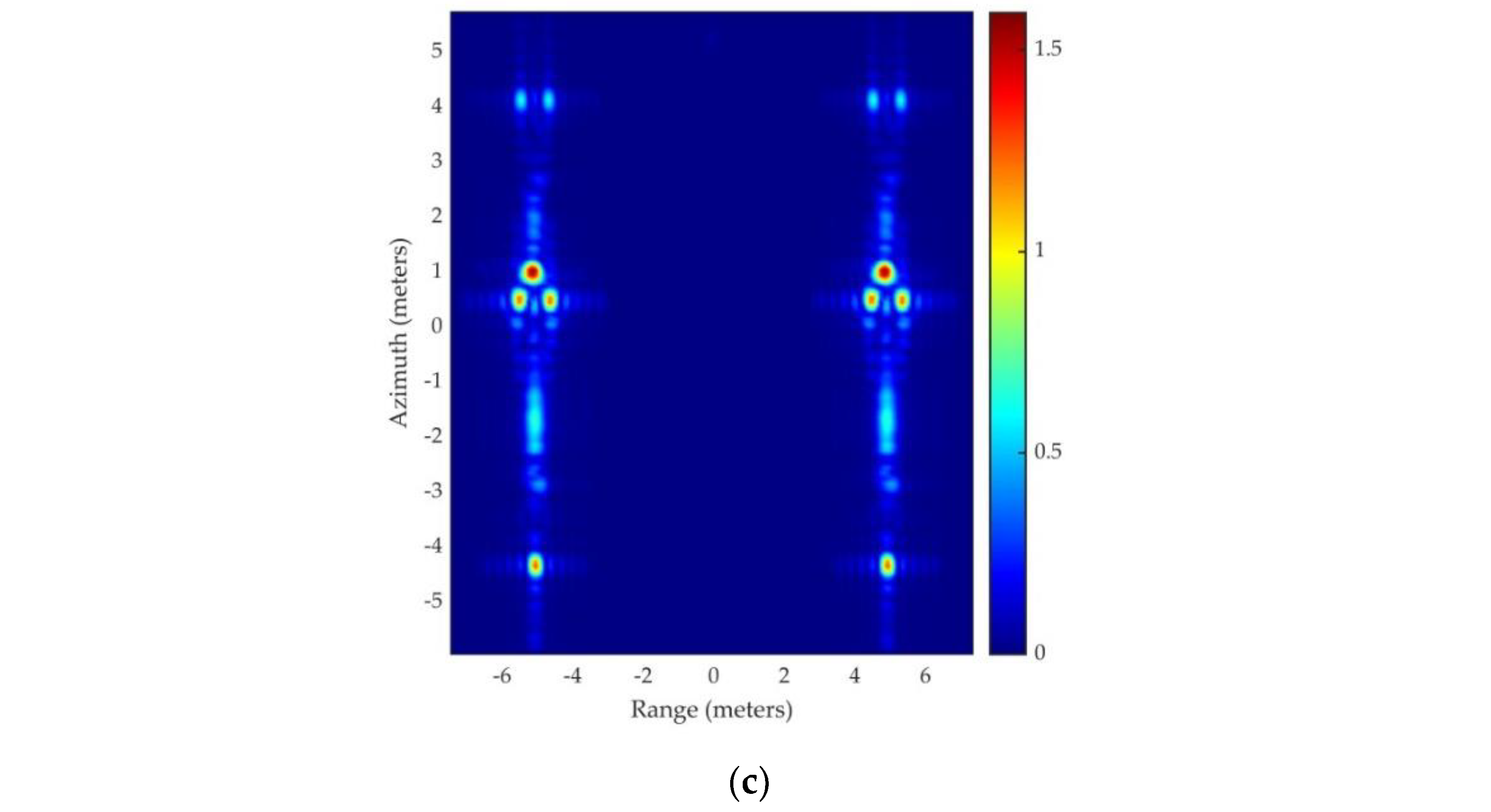
4.2. Targets above Sea Surface

In the following simulations, the SAR images of the missile-like targets above the rough sea surface are analyzed. The size of the electrically large sea surface is 100 λ × 100 λ and the wind speed at 19.5   m above the sea surface is 1   m / s . The incident angle is θ i = 60 ° and φ i = 0 ° .

4.2.1. SAR Images of Different Numbers of Targets above the Sea Surface

In order to detect multiple missile-like targets above the rough sea surface, the SAR images of different numbers of targets above the sea surface are simulated. The height of the target is 10   m above the sea surface. The two targets are parallel to each other and the distance between them is 10   m .
As shown in Figure 13, the texture features of the sea surface can be seen from the SAR image. Although the wind speed at 19.5   m above the sea surface is 1   m / s , which means the sea surface is at a low-sea state, the clutter of the sea surface is strong. When the missile-like target is above the sea surface, the scattered echoes of targets are submerged in the environment clutter. Only the strong scattered centers of the nose-corn and wings part can be distinguished from the environment clutter. Due to the coupling effect among two targets, the backscattering coefficient becomes larger. Therefore, the peak scattering intensities value increases comparing Figure 13b,c. Compared with the SAR images of targets in the free space, it will be difficult to detect the target above the rough sea surface, especially if the target is at an ultra-low altitude.

4.2.2. SAR Images of Different Rotation Angles

In order to detect multiple missile-like targets with different courses above the rough sea surface, the SAR images of different rotation angles of targets above the sea surface are simulated. The height of the target is 10   m above the sea surface. The two targets are parallel to each other and the distance between them is 10   m . The course angles of the targets are 30 ° , 60 ° and 90 ° , respectively.
It can be seen from Figure 14 that the antenna could easily detect the missile-like target from the sea clutter, due to the scattering intensity increasing with the increase of the course angle. Meanwhile, a “mirror” target can be clearly identified in Figure 14c. This is caused by the multi-path coupling scattering between the missile-like target and the rough sea surface [28]. However, the backscattering intensity of the “mirror” target image is much weaker than the real target. According to the experiment in [12], the multi-path scattering will be smaller at the higher sea state, which has been proved by experimental studies and measurement values analysis.

5. Discussion

Comparing the value of RMSE and CPU time between the proposed method and RL-GO and MLFMM solver in commercial software, it can be concluded that the proposed method can improve the calculation efficiency on the premise of ensuring the accuracy. However, it is difficult to detect and identify multiple targets by only analyzing the EM scattering characteristics. Therefore, the HRRP analysis and SAR imaging method are introduced to solve the problem. Through the HRRP analysis, the number of targets, the target projection length in radar LOS, and the scattering intensity of the scatter point can be obtained, which improves the performance of target recognition. Furthermore, the HRRP images database can lay the foundation for subsequent research on intelligent recognition based on the artificial neural network.
In addition, the SAR images are simulated based on the proposed hybrid method. Through SAR image analysis, the projection length, scattering intensities and the strong scattering points of different targets can be clearly identified. With the increase of the target number, the coupling scattering has been strengthened due to the iteration and update process in calculation. However, when the target is occluded, it will be difficult to distinguish the specific position relationship of the targets through the 2-D SAR image, which needs to be solved in the future study. What is more, it is different when analyzing the SAR images of missile-like targets above a rough sea surface, because the clutter of the sea surface is strong, and the scattered echoes from targets will be submerged in the environment clutter. Therefore, the detection and recognition of targets with cluttered background need to be improved, combining by introducing anti-clutter technologies and neural network-based algorithms.

6. Conclusions

In this paper, a near-field modified IPO and facet-based two-scale model are presented for the analysis of composite EM scattering from multiple targets above a rough surface. Through comparative analysis, the correctness and efficiency of the EM scattering algorithm are verified. Moreover, aiming at radar target detection and recognition utilizing HRRP and high-resolution SAR images, a fast imaging method is introduced based on the proposed hybrid EM scattering method. The numerical results show the effectiveness of the proposed method, which can generate backscattering data accurately and obtain HRRP and high-resolution SAR images. Through the HRRP and SAR images analysis, the number of targets, the target projection length in radar LOS, and the scattering intensity of scatter point can be obtained which remarkably improve the detection and target recognition abilities of radar system, especially for multiple ultra-low altitude targets above the sea surface. Although the scattered echoes from targets will be submerged in the environment clutter, the method can be widely applied in target recognition, image classification, scene matching, and so forth. In terms of the future work, through the proposed method, a large HRRP and SAR images database of numerous targets for all observation directions can be obtained. Moreover, an automatic target recognition system of SAR images will be established for a more complicated environment, and the system performance can be further improved by integrating deep learning, fuzzy clustering and generalized regression neural network.

Author Contributions

Conceptualization, C.T. and X.L.; data curation, Q.W. and Y.W.; formal analysis, C.T., Y.W. and Z.W.; funding acquisition, C.T.; investigation, C.T., X.L. and Z.W.; methodology, Q.W. and T.W.; software, Q.W. and Y.W.; supervision, T.W.; visualization, Q.W. and Z.W.; writing—original draft, Q.W.; writing—review and editing, C.T., X.L. and T.W. All authors have read and agreed to the published version of the manuscript.

Funding

This research was funded by National Natural Science Foundation of China, grant number 61901510 and National Science Foundation of Shannxi Province, grant number 2021JQ-362.

Data Availability Statement

Not applicable.

Acknowledgments

Thanks to my instructor Chuangming Tong for his technical assistance throughout the project. I would also like to acknowledge all my friends for their hard work on this paper.

Conflicts of Interest

The authors declare no conflict of interest. The funders had no role in the design of the study; in the collection, analyses, or interpretation of data; in the writing of the manuscript, or in the decision to publish the results.

References

  1. Qi, X.; Nie, Z.; Lu, D.; Wang, Y.; Que, X.; Hu, J. SAR Imaging for Targets within a Half-Space Using Efficient Numerical Simu-lation of Maxwell’s Equation. In 2007 Electromagnetics Research Symposium—Spring (PIERS), St. Petersburg, Russia, 22–25 May 2017; IEEE: Piscataway, NJ, USA, 2017; pp. 1244–1249. [Google Scholar] [CrossRef]
  2. Ngoc, T.M.N.; Linh, M.; Uyen, N.D.; Van Su, T. A 3D Model to Characterize EM Far-FIELD scattering and Its Applications in SAR Data Synthesis. In 2015 International Conference on Advanced Technologies for Communications (ATC), Ho Chi Minh City, Vietnam, 14–16 October 2015; IEEE: Piscataway, NJ, USA, 2015; pp. 633–636. [Google Scholar] [CrossRef]
  3. Kim, S.; Ka, M. SAR Simulation of Realistic Target Using General Purpose EM Simulators. In 2015 IEEE International Conference on Aerospace Electronics and Remote Sensing Technology (ICARES), Bali, Indonesia, 3–5 December 2015; IEEE: Piscataway, NJ, USA, 2015; pp. 1–4. [Google Scholar] [CrossRef]
  4. Dong, C.; Guo, L.; Meng, X. An accelerated algorithm based on GO-PO/PTD and CWMFSM for EM scattering from the ship over a sea surface and SAR image formation. IEEE Trans. Antennas Propag. 2020, 68, 3934–3944. [Google Scholar] [CrossRef]
  5. Li, J.; Zhang, M.; Wei, P. Combination of GO/PO and PTD Method for EM Scattering and SAR Image Simulation from Complex Targets. In 2018 IEEE International Symposium on Antennas and Propagation & USNC/URSI National Radio Science Meeting, Boston, MA, USA, 8–13 July 2018; IEEE: Piscataway, NJ, USA, 2018; pp. 2467–2468. [Google Scholar] [CrossRef]
  6. Zhang, Y.; Li, F.; Qiu, X.; Ding, C. An Approach for Simulating SAR Images of Tanks by Using Shooting and Bouncing Rays. In 2015 IEEE 5th Asia-Pacific Conference on Synthetic Aperture Radar (APSAR), Singapore, 1–4 September 2015; IEEE: Piscataway, NJ, USA, 2015; pp. 474–476. [Google Scholar] [CrossRef]
  7. Wu, X. Advanced Multiple Input Multiple Output (MIMO) SAR Algorithm for High-Resolution 3D Reconstruction Imaging. In 2017 22nd General Assembly and Scientific Symposium of the International Union of Radio Science (URSI GASS), Montreal, QC, Canada, 9–26 August 2017; IEEE: Piscataway, NJ, USA, 2017; pp. 1–4. [Google Scholar] [CrossRef]
  8. Li, Q.; Wang, Y.; Zhang, Y. Investigation on Simulation of Sea Surface SAR Image. In 2021 13th International Symposium on Antennas, Propagation and EM Theory (ISAPE), Zhuhai, China, 1–4 December 2021; IEEE: Piscataway, NJ, USA, 2021; pp. 1–3. [Google Scholar] [CrossRef]
  9. Chiang, C.-Y.; Chen, K.-S.; Yang, Y.; Wang, S. Computation of backscattered fields in polarimetric SAR imaging simulation of complex targets. IEEE Trans. Geosci. Remote Sens. 2022, 60, 2004113. [Google Scholar] [CrossRef]
  10. Peng, P.; Guo, L.X.; Tong, C. An EM model for radar multipath simulation and HRRP analysis of low altitude target above electrically large composite scale rough surface. Electromagnetics 2018, 38, 177–188. [Google Scholar] [CrossRef]
  11. Li, D.; Zhao, Z.; Zhao, Y.; Huang, Y.; Liu, Q.H. An Improved Facet-Based Two-scale model for Electromagnetic Scattering from Sea Surface and SAR Imaging. In 2019 IEEE Radar Conference (RadarConf), Boston, MA, USA, 22–26 April 2019; IEEE: Piscataway, NJ, USA, 2019; pp. 1–4. [Google Scholar] [CrossRef]
  12. Peng, P.; Guo, L.X.; Tong, C. A hybrid EM scheme for the composite scattering and the SAR imaging of a low-altitude target above the electrically large and multi-scale sea surface. Electromagnetics 2017, 37, 1–13. [Google Scholar] [CrossRef]
  13. Yang, W.; Chia, T.T.; Kee, C.Y.; Wang, C.F. SAR Imaging of Surface Target Using High Frequency Electromagnetic Method. In 2015 IEEE 5th Asia-Pacific Conference on Synthetic Aperture Radar (APSAR), Singapore, 1–4 September 2015; IEEE: Piscataway, NJ, USA, 2015; pp. 161–162. [Google Scholar] [CrossRef]
  14. Peng, P.; Guo, L.X.; Tong, C.M. A SAR Imaging Simulator of a Low-Flying Target above Ocean Surface with Multipath Effect. In 2017 IEEE International Conference on Signal Processing, Communications and Computing (ICSPCC), Xiamen, China, 22–25 October 2017; IEEE: Piscataway, NJ, USA, 2017; pp. 1–4. [Google Scholar] [CrossRef]
  15. Zhang, M.; Zhao, Y.; Nie, D. EM Scattering and SAR Image Simulation from Composite Sea-Ship Scene Based on a Weighted Multi-Path Model. In Remote Sensing of the Ocean, Sea Ice, Coastal Waters, and Large Water Regions 2016; SPIE: Bellingham, WA, USA, 2016. [Google Scholar]
  16. Diao, G.; Huitong, J.; Ni, H.; Liu, Z.; Gon, N.; Yang, L. Study on the Modeling Method of Sip Target for Uav-Borne Bi-SAR. In 2020 3rd International Conference on Unmanned Systems (ICUS), Harbin, China, 27–28 November 2020; IEEE: Piscataway, NJ, USA, 2020; pp. 903–907. [Google Scholar] [CrossRef]
  17. Deng, Y.; Wang, H.; Liu, S.; Sun, M.; Li, X. Analysis of the ship target detection in high-resolution SAR images based on information theory and Harris corner detection. J. Wirel. Com Netw. 2018, 2018, 291. [Google Scholar] [CrossRef] [Green Version]
  18. Jafari, S.; Lal, A.M.; Jagalingam, P. Ship detection based on information theory and segmentation from synthetic aperture radar (SAR) images. Int. J. Recent Technol. Eng. 2020, 8, 2513–2517. [Google Scholar] [CrossRef]
  19. Feng, T.; Guo, L. Multiview isar imaging for complex targets based on improved sbr scattering model. Int. J. Antennas Propag. 2021, 2021, 1–10. [Google Scholar] [CrossRef]
  20. Stateczny, A.; Kazimierski, W.; Gronska-Sledz, D.; Motyl, W. The empirical application of automotive 3D radar sensor for target detection for an autonomous surface vehicle’s navigation. Remote Sens. 2019, 11, 1156. [Google Scholar] [CrossRef] [Green Version]
  21. Liu, W.W.; Liu, Y.C.; Bucknall, R. Filtering based multi-sensor data fusion algorithm for a reliable unmanned surface vehicle navigation. J. Mar. Eng. Technol. 2022, 1–17. [Google Scholar] [CrossRef]
  22. Mehmood, K.; Jalil, A.; Ali, A.; Khan, B.; Murad, M.; Khan, W.U.; He, Y.G. Context-aware and occlusion handling mechanism for online visual object tracking. Electronics 2021, 10, 43. [Google Scholar] [CrossRef]
  23. Zhang, T.D.; Liu, S.W.; He, X.; Huang, H.; Hao, K.D. Underwater target tracking using forward-looking sonar for autonomous underwater vehicles. Sensors 2020, 20, 102. [Google Scholar] [CrossRef] [PubMed] [Green Version]
  24. Chen, B.; Tong, C. Modified physical optics algorithm for near field scattering. Chinese Phys. B 2018, 27, 114102. [Google Scholar] [CrossRef]
  25. Zou, G.; Tong, C.; Zhu, J.; Sun, H.; Peng, P. Study on composite electromagnetic scattering characteristics of low-altitude target above valley composite rough surface using hybrid SBR-EEC method. IEEE Access 2020, 8, 72298–72307. [Google Scholar] [CrossRef]
  26. Wang, T.; Tong, C. An Improved facet-based tsm for electromagnetic scattering from ocean surface. IEEE Geosci. Remote Sens. Lett. 2018, 15, 644–648. [Google Scholar] [CrossRef]
  27. Tian, G.; Tong, C.; Sun, H.; Zou, G.; Liu, H. Improved hybrid algorithm for composite scattering from multiple 3D objects above a 2D random dielectric rough surface. IEEE Access 2021, 9, 4435–4446. [Google Scholar] [CrossRef]
  28. Chen, B.; Tong, C. Radar multipath scattering from the composite model: Specular image modified model and ISAR imaging analysis. Int. J. RF Microw. Comput. Aided Eng. 2019, 29, e21956. [Google Scholar] [CrossRef]
Figure 1. The geometry of the HRRP image from a jet fighter.
Remotesensing 14 02910 g001
Figure 2. SAR slant range and squint angle geometry.
Remotesensing 14 02910 g002
Figure 3. The monostatic scattering from two missile−like targets.
Remotesensing 14 02910 g003
Figure 4. The bistatic scattering from two missile−like targets above the electrically large rough sea surface.
Remotesensing 14 02910 g004
Figure 5. The location distribution of the missile−like targets: (a) at the same height above the rough sea surface and parallel to each other; (b) at a different height above the rough sea surface and parallel to each other; (c) at the same height above the rough sea surface and in a tandem array.
Remotesensing 14 02910 g005
Figure 6. The monostatic RCS of two PEC missile−like targets: (a) in the HH polarization; (b) in the HV polarization; (c) in the VH polarization; (d) in the VV polarization.
Remotesensing 14 02910 g006aRemotesensing 14 02910 g006b
Figure 7. The bistatic scattering: (a) from the electrically large rough sea surface without or with one or two missile−like targets above it; (b) from two missile−like targets above the electrically large rough sea surface at a different height.
Remotesensing 14 02910 g007
Figure 8. The HRRP image of two missile−like targets with different location distribution.
Remotesensing 14 02910 g008
Figure 9. SAR images of missile−like targets in the free space: (a) one target; (b) two targets; (c) four targets.
Remotesensing 14 02910 g009
Figure 10. SAR images of missile−like targets in the free space: (a) two targets located at the same height and in a tandem array in the free space; (b) two targets located at a different height and parallel to each other in the free space; (c) two targets located at the same height and parallel to each other in the free space.
Remotesensing 14 02910 g010
Figure 11. The geometries of different types of missile−like targets: (a) Type 1; (b) Type 2; (c) Type 3.
Remotesensing 14 02910 g011
Figure 12. SAR images of different types of missile−like targets: (a) Type 1; (b) Type 2; (c) Type 3.
Remotesensing 14 02910 g012aRemotesensing 14 02910 g012b
Figure 13. SAR images of a different number of missile−like targets above sea surface: (a) only the rough sea surface; (b) one missile−like target above sea surface; (c) two missile−like targets above the sea surface.
Remotesensing 14 02910 g013
Figure 14. SAR images of two missile−like targets with different courses above sea surface: (a) rotation angle 30 ° ; (b) rotation angle 60 ° ; (c) rotation angle 90 ° .
Remotesensing 14 02910 g014
Table 1. The RMSE and CPU time of different methods.
MethodRMSECPU Time (s)
The Proposed Method0.1600646
MLFMM solver0.00006607
RLGO solver0.767856
Publisher’s Note: MDPI stays neutral with regard to jurisdictional claims in published maps and institutional affiliations.

