Abstract
A lot of architectural heritage in China are urgently in need to carry out seismic assessment for further conservation. In this paper, a seismic capacity evaluation approach for architectural heritage using finite element analysis with precision three-dimensional data was proposed. The Limestone Hall of Shaanxi Province was taken as an example. First, low attitude unmanned aerial vehicle photogrammetry and a close-range photogrammetry camera were used to collect multiple view images to obtain the precision three-dimensional current model of the Limestone. Second, the dimensions of internal structures of Limestone Hall are obtained by means of structural analysis; re-establishing the ideal model of Limestone Hall based on the modeling software. Third, a finite element analysis was conducted to find out the natural frequency and seismic stress in various conditions with the 3D model using ANSYS software. Finally, the seismic capacity analysis results were comprehensively evaluated for the risk assessment and simulation. The results showed that for architectural heritage with a multilayer structure, utilizing photogrammetric surveying and mapping, 3D software modeling, finite element software simulation, and seismic evaluation for simulation was feasible where the precision of the modeling and parameters determine the accuracy of the simulation. The precise degree of the three-dimensional model, the accurate degree of parameter measurement and estimation, the setting of component attributes in the finite element model and the strategy of finite element analysis have an important effect on the result of seismic assessment. The main body structure of the Limestone Hall could resist an VII-degree earthquake at most, and the ridge of the second floor could not resist a V-degree earthquake due to unsupported conditions. The maximum deformation of the Limestone Hall during the earthquake occurred in the tabia layer below the second roof.
1. Introduction
There are numerous items of cultural heritage in China, with the total number ranking second in the world. However, many of these cultural heritage item face major threats due to the impact of geological disasters such as earthquakes. Limited by economic conditions and technical capabilities, a large number of Chinese cultural heritage item, in particular architectural heritage, lack accurate mapping information and structural models available for analysis and research, so effective seismic assessments cannot be carried out. As a result, they are often vulnerable to irreparable damage during earthquakes. Therefore, it is of necessary and urgent need to carry out seismic evaluation and research on architectural heritage in China.
Regarding current research in the field of earthquake resistance of architectural heritage, stress response and the damage mechanism of architectural heritage during earthquakes have been analyzed by theoretical model establishment and software simulation, experimental tests, monitoring data feedback and other methods, and then measures of seismic performance improvement have been given or seismic guiding principles proposed. In the aspect of theoretical model establishment, existing research into the mechanics of various materials and structural mechanics have been mainly used as references, and an improved theory of mechanics or models have also been adopted as research support [1,2,3,4,5], the simulation analysis tools mainly used are finite element analysis (FEA) software such as ANSYS [6,7,8,9,10], 3Muri [11,12,13], ABAQUS [14,15], SATATS [16], BrickWORK [17], TREMURI [18], etc.; from the aspect of experimental testing, earthquake response characteristics have usually been obtained by the shaking table test [19] and ambient vibration tests [20,21,22], the intensity index is mainly detected by the triaxial compression test [23]; from the aspect of data monitoring, data obtained by monitoring tend to be used for structural safety assessments and structural strength improvement [24,25,26,27]; at the time of studying earthquake damage mechanisms, there have been macroscopic assessments for architectural heritage for some materials or structures [28,29,30,31,32], and in-depth assessments on architectural heritage monomers [33,34,35].
The studies mentioned provide a necessary reference for the seismic analysis and evaluation of architectural heritage, but there are still some problems to be improved. First, the seismic calculation model established for architectural heritage in most research is relatively simple and is not strictly in accordance with accurate measurement data. Inaccurate data make the analysis results have a larger deviation and may even influence the judgment of structural safety. Second, there are no complete and clear work methods and implementation standards need to be further elaborated for architectural heritage from accurate mapping, digital model establishment, mechanical characteristic simulation, and seismic analysis to results assessment. Third, many studies have focused on architectural heritage with homogenous materials or simple structures. As for the kinds of responses of architectural heritage built using multiple composite materials and with complex structures at the time of the earthquake, there is little research experience at present.
In 2017, Chang’an University and the Cultural Relics Bureau of Shaanxi Province jointly cooperated to study an extremely special ancient building with a history of over 400 years in Western China. The study obtained its dimensional data through photogrammetry, revealed its design theories and construction process in the form of virtual simulations, evaluated its seismic performance by analyzing its mechanical characteristics in detail and realized exquisite exhibition and in-depth interpretation of the building. As the sandwich type of structure, made up of “limestone-tabia–limestone-tabia-limestone”, adopted by its measurements, modeling, and seismic analysis faced multiple unprecedented problems. It is the first time such work has been implemented in China and is of great significance. The basic principles and working methods of architectural heritage with complex structures at the time of measurement, virtual modeling, and seismic analysis are mainly elaborated in this paper and the research object of the Limestone Hall of Xuanwu Temple was combined for detailed discussion.
2. Background
2.1. Overview of Limestone Hall of Xuanwu Temple
The “Black tortoise” is derived from the ancient Chinese belief in “four souls”. It is a virtual animal and described as a combination of a tortoise and snake, who are in charge of the north. The Black tortoise is called the “Xuanwu Emperor” at the time of incarnation with majesty and power. Xuanwu Temple is a Taoist temple that especially sacrifices to the Xuanwu Emperor.
The Limestone Hall of XuanwuTemple (Figure 1) is located 10.5 km southwest from Heyang County, Shaanxi Province, China. It was established in a towering earth hummock. At the top of the earth hummock, a platform was built with green bricks, and the Limestone Hall is located in the central north of the platform (Figure 2). The bottom of the Hall is arranged with a stylobate with an east-west width of 9 m, south-north width of 9.25 m and height of 0.06 m. The plane of the hall is square with a side length of 8.01 m and height of 9.04 m. Nearly 700 lime stones were used to build the Hall, which is a wood-like structured double-eave irimoya. Exquisite relief patterns are sculptured in the stones of the outer wall of the Hall. An arch (Figure 3a) is set in the middle of the southern side of the Hall, and inside the arch is a barrel arch serving as the corridor to enter the Hall. The internal hall was built by a stone wall close to square in plane with an east-west width of 4.33 m and south-north depth of 4.38 m. A stone oblique beam was built in four corners of the internal wall in a position 1.89 m high away from ground (Figure 3b); multiple stone posts were used to overhang internally and converge in the center of the top of the hall generally and then became octagonal superimposed domes (Figure 3c). A statue of the Xuanwu Emperor is arranged in the temple.
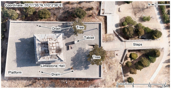
Figure 1.
General layout orthophoto of the Limestone Hall.
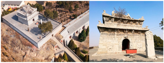
Figure 2.
Full view of the Limestone Hall and direction of the southern entrance.
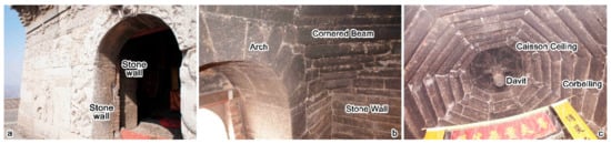
Figure 3.
Detail of the structure of the Limestone Hall (a) the arch in the south of Limestone hall, (b) interior wall and inclined beam of Limestone hall, and (c) the octagonal dome in the interior of the Limestone Hall.
The structure of the Limestone Hall is unique. Through analysis and research (see below for details), there is still a layer of wall between the external wall and the internal wall. Tabia was used between the layers of the walls (Figure 4), which forms a five-layer composite structure of “limestone-tabia-limestone-tabia-limestone”.
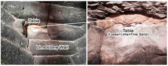
Figure 4.
Tabialayer exposed from internal stone damage of the Limestone Hall.
The Limestone Hall was built in the 32nd year of Wanli’s Reign in the Ming Dynasty (AD 1604), which has a history of over 413 years. Its special structure of “stone-soil-stone-soil-stone” is very rare, so it has been listed by the national key cultural relics protection unit, which is part of the government of China.
2.2. Research Objects and Current Problems
The objective of this study was to realize a 3D digital reconstruction of the Limestone Hall and precision 3D documentation for the seismic assessment and digital conversation. The ideal model of the Limestone Hall can be used to guide future repair work, which can not only reveal the special structure of the Hall, but also analyze the appearance deformation through a comparison with the current 3D model. Then a mechanical model, which can be used to evaluate the seismic capacity of the Hall, was created to scientifically analyze and evaluate the structural safety of the Limestone Hall and find the locations where structural reinforcement is needed.
As the compound structure method of “stone-tabia-stone-tabia-stone” was adopted by the Limestone Hall, the difficulty of related research has obviously increased with the main confronting problems as follows:
- (1)
- Problem at the time of mapping. As the outdoors and indoors of Limestone Hall are two independent parts, the question of how to collect data to guarantee the establishment of complete model is one issues; as the indoor Limestone Hall is relatively close which makes it dim, we had the problem of how to guarantee that images collected indoors had a good effect.
- (2)
- Problems in establishing current 3D models and ideal models. The Limestone Hall has nearly 700 stones and filling loess without fixed forms. The question of how to establish models for them; how to analyze and reveal the construction mode of the multilayer structure of the Limestone Hall needed to be resolved, as was how to use the ideal model and the current status model to implement a comparison analysis to find out damage and sedimentation position of Limestone hall at present.
- (3)
- Problems of the seismic analysis with 3D digital model. How could we convert the three-dimensional model to be a model that can provide the stress calculations and estimate all the technical parameters accurately; what are the differences between the ideal status and the current status of the Limestone Hall, how to set up material parameters under the current status; how to analyze destruction condition of Limestone Hall under the different earthquake force; and how to judge or inspect the accuracy of seismic analysis results were also problems that needed to be resolved.
3. Research Strategies
3.1. The Technical Flow Chart and Technical Defects
Low attitude UAV-based photogrammetry was presented to obtain images of the exterior of the Limestone Hall and surrounding environment in this research. Ground close photogrammetry technology was adopted to match the auxiliary lighting means to obtain the interior parts of the Limestone Hall. A total station was used to collect control-point coordinates indoors and outdoors. Smart3D software (made by Acute3D Inc., Sophia Antipolis, Frence). was used with the help of control-point coordinates to combine the indoor and outdoor point cloud and generate a triangular network model, then the non-editable current three-dimensional model was generated by the texture maps, and the model imported into 3Dmax software (made by Autodesk Inc., SAN Rafael, CA, USA) to establish a separable model again before the established model was imported into ANSYS software (made by ANSYS Inc., Pittsburgh, PA, USA). The model was simplified in the software and parameters were set up. Finite element analysis was implemented for the models to calculate the intrinsic frequency, gravity load, earthquake load, snow load, and combined load of the Limestone Hall under the ideal status, and the limit of seismic capacity was obtained. Then, the limit of seismic capacity of Limestone Hall under its current status at present was calculated, and a comprehensive evaluation was implemented for the results and corresponding strengthening recommendations were proposed (Figure 5).
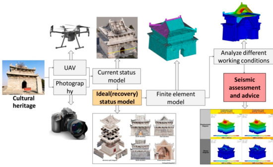
Figure 5.
Digitization and earthquake resistance analysis flow diagram of architectural heritage with multilayer structures.
Technical defects of the research are that: three imports into different software are required for adjustment at the time of modeling. The process is complex, and accuracy of the model will be reduced slightly. In the calculation of finite element, the parameters of the research object need to be acquired. However, as the Limestone Hall is the national key cultural relics protection unit, the cultural relics management personnel favors non-contact research, and we are not allowed to collect stone material and excessive tabia from the Hall, so that the relevant parameters of the stone and the tabia can only be measured according to the similar materials, leading to certain errors in the result. In addition, the environmental vibration test is helpful somehow in verifying the accuracy of the ANSYS model, but as the management personnel is concerned about unknown damage to the cultural relics, we are not allowed to conduct such tests, so that the calculation results such as the natural frequency, etc. cannot be further corrected.
3.2. Specific Implementation Processes
3.2.1. Multi-View Photogrammetry Data Collection to Establish Current Status 3D Model
An unmanned aerial vehicle, digital single lens reflex, and total station were used to collect data in the stage of field operation. Smart3D software was used to generate a point cloud after processing the obtained internal and external data in the stage of internal operation. Cloud fusion was implemented according to data from the total station, and a triangular network model was generated. After texture mapping, a non-editable three-dimensional current status model was obtained (see Figure 6 for the operation steps).
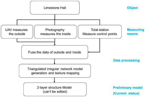
Figure 6.
Mapping and modeling flow diagram of architectural heritage with multilayer structures.
Collecting External Data of Limestone Hall by Unmanned Aerial Vehicle Aerophotogrammetry
A multi-rotor was used for oblique aerial photogrammetry. Image data of large-scale scenes of the temple were obtained before the external image data of a single building. Control points of aerial photography were arranged in obvious positions of ground and buildings. The total station was used to measure the control points. Multiple software can be used to process aerial stereo images. Balancing settlement was implemented by the automatic matching of the system according to the image control point, the result of the aerial triangulation was output, and the DSM point cloud data were generated by intensively matching discrete points, and the DTM point cloud data were obtained after interference removal.
The mapping adopted a self-assembled, eight-rotor five-lens UAV, which was manufactured by Zoller + Fröhlich (Shanghai) with a single lens pixel of 24 million, lateral total FOV of 125°, flight height of 25 m, and an image resolution of approximately 0.6 cm. The ground control points were selected at the four corners of the enclosure wall of the brick masonry platform, the four corners of the roof of the Limestone Hall: the top of the ridge, four corners of the bottom of the stylobate, the top of the door opening, and the bottom of the door opening (Figure 7). Four sorties were flown by the UAVs, with the flying distance of each sortie at the time of mapping being about 600 m and a duration of 15–20 min. Eight hundred images were obtained in total. Images generated the point cloud data after the automatic processing of Smart3DCapture.
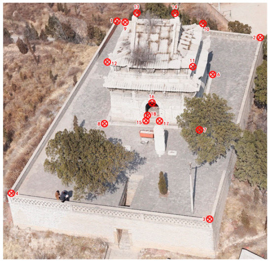
Figure 7.
Layout diagram of the external control points of the Limestone Hall.
Collecting Internal Data of Limestone Hall by Close-Range Photogrammetry
The indoor space of the Limestone Hall is narrow, so it is simple and effective to collect data through the photogrammetry method. When shooting, artificial light was used to increase the brightness of the room, and the camera was fixed with an increase in the exposure time of the picture, so that the ISO was controlled below 600. In order to guarantee effective matching with external data of the building, a more careful collection process was implemented in the door opening position between the internal and external parts at the time of the indoor shot, and part of the outdoor images outside the door opening were shot. The highest point of the dome and the intersection points of the dome and the four corners of the wall were selected as the indoor control points. In addition, the control points at the top position of the door opening were taken simultaneously by the UAV and the ground camera to ensure smooth data fitting.
A Sony A7R2 type camera was used to map the Limestone Hall. More than 300 ground images were obtained in total. Images were used to generate the point cloud data after automatic processing with the Smart3DCapture software (made by Acute3D Inc., Sophia Antipolis, Frence).
Internal and External Data Fusion of the Limestone Hall
The control-point coordinate was utilized to convert all of the internal and external point cloud data into a practical engineering coordinate system, and then the point cloud data generated by the aerial photography from the external UAV was used as the benchmark. A DTM point cloud generated by the internal photography measurements were provided with corresponding points matching by utilizing the iterative closest point (ICP) algorithm, and two kinds of point cloud data can be combined. This combination for point cloud data in the Limestone Hall was subjected to Cyclone software (made by Leica Inc., Oskar-Barnack-Straße, Germany), and took about 10 min.
Current Status Model Generation of Limestone Hall to Obtain a Triangulation Network Model and Conduct Texture Mapping
Point cloud data after combination was subjected to the incremental insertion algorithm to generate a triangulation network (TIN) in the Cyclone software, and images from the UAV aerial photography and indoor collection were taken as texture mapping in the TIF format to be mapped onto the triangulation network model in Smart3DCapture software or 3Dmax software. A realistic as-build 3D digital model based on a real coordinate system was obtained.
During this work, a model (Figure 8) in .s3c format was generated by utilizing Smart3DCapture software, which can be used for quick browsing, and the mode accuracy was better than 1 cm. The size data can be obtained from the model through measurement; the model (texture automatically linked in .mtl format) in the .obj format can be generated by utilizing 3ds Max software, which can be taken as the reference model at the time of follow-up modeling.
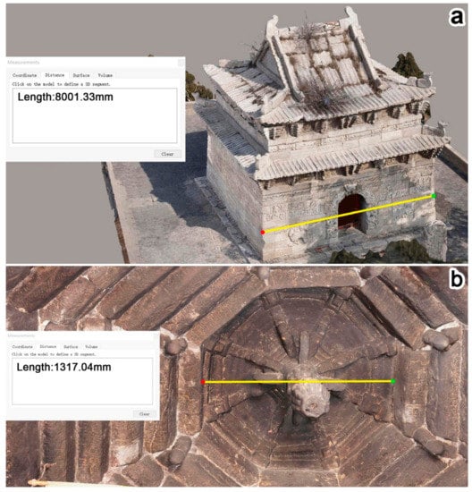
Figure 8.
Measurable model established by smart3d software (a) Measurement for external model; (b) Measurement for the internal model.
3.2.2. Current Status Model Analysis and Establishment of Separable Model
Although the as-built three-dimensional model is very vivid, it is actually made up of external and internal surface layers that cannot be disassembled and analyzed; therefore the calculation of mechanical simulation and anti-seismic performance cannot be carried out. Thus, it is subject to the current status model for reference, and a more intuitive, editable and separable model shall be established again. First of all, the current status model shall be provided with a size analysis, and the specific position for all structural layers of the building shall be specified. Binary opposition for all structural layers shall be specified and the set-up mode for the structure shall be speculated in reverse through the location information. A separable model can be established on this basis, and the specific procedures are shown in Figure 9.
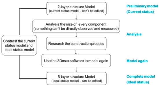
Figure 9.
Structure analysis of architectural heritage with multilayer structure and flow diagram of model reconstruction.
Structural Analysis According to the Model Data and Real Photos
Through measurements for the wall and position of all members in the current status model, combined with real photos from the same time, the following phenomenon as found:
First, it was observed that there was another stone wall inside the external wall through cracks in the Limestone Hall, and tabia residues (Figure 10a,b) were retained between the stone wall and the external wall. It was observed that the tabia appeared at the inside of the vault through an internal crack in the Hall (Figure 4), and the tabia appeared at the junction of the arch of the Hall (Figure 10c). The tabia also appeared in cracks in the flagstones on the roof of the Limestone Hall.
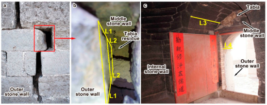
Figure 10.
Structural layer analysis of limestone hall and dimension measurement of all layers. (a) Out-wall crack in the north of limestone hall; (b) Architectural structure seen from crack of north wall; (c) Architectural structure seen from south of inside limestone hall.
Second, through measurements of the current status model, it was found that the horizontal distance of the external surface of the wall under the second-floor eave in the Limestone Hall to the external wall was equal to that from the stone wall inside the external wall to the external wall (L1+L2, showed in Figure 10b), which showed that the stone wall inside the external wall extended into the wall supporting the second floor eave vertically.
Third, the thickness of the interior high arch in the south side of the Limestone Hall (L3, showed in Figure 10c) is very close to the horizontal distance of the external surface of the wall under the second-floor eave in the Limestone Hall to the external wall. The thickness of the exterior low arch in the south side of the Limestone Hall (L4, showed in Figure 10c) is very close to the sum of L1 plus L2. In addition, the width of the L3 can be judged to be the total width of the inner wall, the tabia and the middle-layer wall according to the stone stacking mode of the inner side surface of the high arch.
Fourth, the flagstone supporting the Limestone Hall can be seen under the second-floor eave, and this flagstone was 5.40 m away from the indoor ground. The highest point indoors of the internal dome was 4.99 m away from the ground, implying that there was a certain space between the flagstone and the dome. Tabia was used to fill the space, otherwise the flagstone could not be suspended and laid.
The above phenomena showed that the structure of the Limestone Hall was a stone wall in the external layer, tabia, stone wall in the middle layer, tabia, and stone wall in the internal layer from the outside to the inside successively, and was successively stone wall in the internal layer, octagonal dome, tabia, horizontal flagstone layer, tabia and slanting flagstone at the roof. The dimensions of each member could be taken directly from the current status model or indirectly obtained by calculation.
Utilize the Current Status Model to Conduct Remodeling
The current status model in the .s3c format can be used to quickly browse and measure, but the current status model in the .obj format can be imported into 3Dmax software to be used for remodeling. In the 3Dmax software, the current status model is taken as the basic size for reference and the obtained position information and other size information can be analyzed combined with the structure. The ideal model (Figure 11) is separable and can be established according to the following procedure: (1) Lay the external platform through paving bricks; (2) Lay the internal platform through paving bricks; (3) Establish the internal wall of limestone; (4) Build rocky oblique beams at the four corners of the internal wall, and build an arch at the south side; (5) Utilize an oblique beam to corbel internally to form an octagonal dome; (6) Establish a center wall composed of limestone; (7) Build an arch at the south side of the center wall; (8) Establish an external limestone wall; (9) Fill with tabia between the external wall and the center wall; (10) Establish a 2-layer wall and a bucket arch; (11) Fill with tabia between the center wall and the dome roof; (12) Lay a limestone slate on the tabia soil layer of which the upper part shall be parallel and level with the top for the bucket arch layer; (13) Lay a stone ring beam in the center position of the limestone slate; (14) Vertical rammed section inside stone ring beam is the triangular tabia pile, and lay roof flagstones for Irimoya on mound; and (15) Install stones on the roof to be a ridge, install a wooden door under the lower part of the barrel arch, lay the statue of the Xuanwu Emperor indoors, and complete construction.
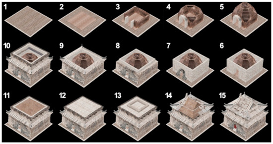
Figure 11.
Construction process diagram of the Limestone Hall.
From the perspective of the established separable model (Figure 12), there was a five-layer structure from the outside to the inside, which was consistent with the structure level deduced from the previous analysis.
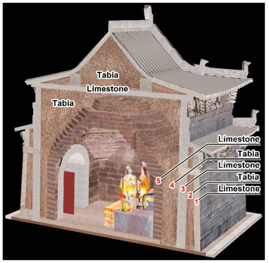
Figure 12.
Profile analysis diagram of the Limestone Hall with a five-layer structure.
3.2.3. Establishment and Calculation of the Finite Element Model
Utilize an editable model to create a corresponding finite element model, set the related technical parameters, and calculate the mechanical response characteristics for the building structure under various loads based on research to obtain effective evaluation results. The specific operation procedures are shown in Figure 13.
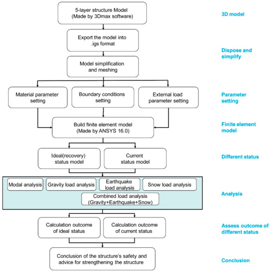
Figure 13.
Finite element modeling and earthquake resistance analysis process diagram of architectural heritage with multilayer structure.
At the time of the setting material parameters, it is necessary to comprehensively consider the characteristics at the time of the material cladding, especially the influence of the adhesive on the masonry structure. When the material parameters fluctuate within some scope, the limit value that makes the destructive influence become large shall be taken; at the time of setting the external load, earthquake load analysis or snow load analysis exclusive in per area can be taken for reference. In order to effectively evaluate the destructive mechanism in case the calculated structure resists the maximum value of seismic force generated by local earthquake, the earthquake force of what kind will destroy the structure needs to be calculated.
Model Simplification and Meshing of Limestone Hall
Import an established editable model from 3Dmax software into files in the .igs format, then import this file into ANSYS software, and use this model as a reference to conduct remolding and set related parameters.
In order to guarantee effective calculation, the model should be properly simplified, and all members set as suitable structure units. The main structure of the Limestone Hall is divided into two types: one is a thin plate-like stone slab or a tabia layer, and the other is a square box-shaped solid rock or tabia. It is suitable to simulate the two by adopting the shell unit and the solid unit respectively. In addition, both units should be set as secondary units that can be finer than the primary unit when subjected to stress analysis. Among them, the top plate, ridge, and ring beam at the upper part of the second-floor were subjected to the shell unit (SHELL281) for modeling, and the internal wall, center wall, external wall and filled tabia were stimulated by the solid unit (SOLID186). Then, the Limestone Hall was covered in mesh. As the structure was too complex, the mesh quantity was properly reduced, and subjected to comprehensive meshing for division. The regular structure was subjected to a hexahedron for division, and the irregular structure subjected to a tetrahedron for division. There are relatively small members in the Limestone Hall, such as the height of per layer of the top of the corbelling dome is only 80 mm, which is the smallest size in a single member. When a larger-sized mesh is used for partitioning, it is impossible to accurately simulate it, and when an extra-small mesh is used, the calculation is too complex and thus unnecessary. So, the minimum size of the single member of 80 mm is used as the basis for dividing the structural mesh. The mesh size was set as 80 mm and was subject to a secondary-unit for division. The quantity for the generated quantity was 2,534,588 in total, and the node quantity was 867,374. The global mesh model was finally obtained and is shown in Figure 14. The units for the model calculation are: length in mm, pressure in MPa, force in N, quality t, and time in s. It should be noted that the non-linear analysis results in a more accurate calculation result, especially having certain advantages in describing the stress of the tabia. However, as the elastic modulus of the tabia is much lower than that of limestone, the effect of the tabia on the overall stiffness of the structure is negligible. The difference in data estimated using two analytical methods is very small. In addition, more relevant data need to be collected if using non-linear analysis, but we are prohibited from collecting stone pieces and necessary amount of tabia from the cultural relic body, so the performance of the material can only be tested by using the same kind of materials, and the data itself has certain error. If more parameters are added, more uncertainties will be actually added, affecting the accuracy of non-linear analysis results. Therefore, linear analysis is adopted for the simulation calculation.
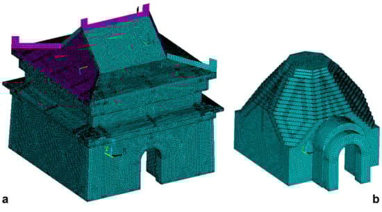
Figure 14.
Finite element model of limestone hall established in ANSYS. (a) Mesh diagram of external structure of limestone hall; (b) Mesh diagram of internal structure of Limestone Hall.
Boundary Condition and External Load Setting of Limestone Hall
The Limestone Hall is fixed on the stylobate laid by bricks through the cohesion, and the specific fixation mode cannot be determined. The rigid fixation constraint was deemed between Limestone Hall and the stylobate in this calculation. The connection mode between the multilayer structures inside the Limestone Hall is set as a “common node”. Three kinds of load generated by gravity, earthquake, and snow were analyzed in this research, and the acceleration for gravity and earthquake exerted an acceleration load to the whole building. The snow load exerted a uniformly distributed load on the roof and the special load parameters are shown in Table 1. The response spectra used in the seismic calculations were in accordance with the Code for Seismic Design of Buildings in China (GB50011-2010).

Table 1.
Related technical parameters of location of Limestone Hall.
Analysis and Setting for Related Parameters of Limestone Hall
The Limestone Hall is mainly composed of an internal wall, center wall, external wall, roof, corner post, door, and filling soil, of which the internal wall, center wall, external wall, roof, and the corner post are made of limestone materials. Tabia was used to fill between the external wall and the center wall, the center wall and the internal wall, and inside the roof. Its material parameters are given in Table 2. Since the Limestone Hall is the important cultural relics under the State protection, we cannot collect stone pieces from it and but are only allowed to collect a small amount of tabia for preliminary testing. The tabia data in the table come from the data obtained from the tabia that we re-prepare of similar colors and compositions. There is a stone quarry nearby which is very close to the stone used in the stone house, and we tested the stone parameters of the quarry to replace the parameters of the Limestone Hall.
Table 2.
Material parameters of the Limestone Hall.
Anti-Seismic Performance Calculation of the Limestone Hall
The limestone model in the ideal status of parameters that was set in ANSYS software was provided during the modal analysis, and the first 10-order frequency and vibration chart were obtained. The working condition for the limestone model under the gravity load, earthquake load (0.15 g acceleration), and snow load were respectively analyzed to obtain the corresponding displacement diagrams and stress diagrams (Figure 15). Calculations were conducted after combining the above three kinds of working conditions to obtain the displacement nephogram and stress nephogram (Figure 15) of the Limestone Hall in the ideal status when three loads were applied at the same time.
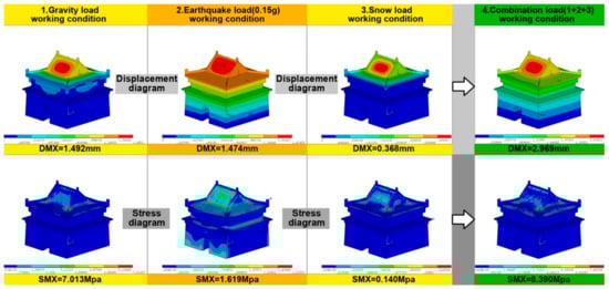
Figure 15.
Displacement nephogram and stress nephogram of the Limestone Hall with an ideal status under three loads of gravity, earthquake, snow, and the combined load.
Under the combined working conditions of three kinds of loads working at the same time, the maximum stress of the Limestone Hall was 8.390 MPa, not reaching the stress limit 10.2 MPa for limestone. Therefore, the combined working condition of the Limestone Hall under greater earthquake acceleration was analyzed again to research its destruction. Under the condition where other parameters remained unchanged, the earthquake acceleration was changed to 0.20 g, and the Hall provided with the combined working condition calculation for three kinds of loads to find out that the maximum stress of the Hall was 10.471 MPa to obtained comparative results of the Hall in the ideal status under the earthquake acceleration of 0.15 g and 0.20 g.
Apart from analyzing the Hall under an ideal status, we also needed to analyze the current status at present. According to the present situation of the Limestone Hall, the ridge has been damaged, and partial flagstones on the roof have been settled or displaced (Figure 16a). In addition, there are obvious cracks in the central part of the north wall and the northern side of the east wall (Figure 16b), which has resulted in a large amount of tabia loss at these positions between the outer wall and the middle wall (Figure 10b), so the tabia layer of the position should be removed when the damaged state is analyzed.
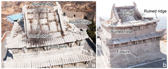
Figure 16.
Damage conditions of limestone hall at present. (a) Ridge damage in the south and roof sedimentation; (b) Northern roof sedimentation and crack on the wall.
The analysis procedure of the Limestone Hall in the current status was the same as that in the ideal status. Through calculation, under the combined working conditions of the dead weight load, earthquake load (0.15 g) and snow load, the maximum stress of the Hall in the damaged state was 9.077 MPa. Due to the fact that the stress limit 10.2 MPa of the limestone was not reached, under the condition that the other parameters remain unchanged, the earthquake acceleration was changed to 0.20 g, and the combined working condition calculation was conducted to obtain that maximum stress of the Hall, which was 11.172 MPa, to get comparative results of the Hall in the current status under the earthquake acceleration of 0.15 g and 0.20 g.
4. Result and Related Discussion
4.1. Current Status Model, Recovery Model and Stress Calculation Result
The 3D model could accurately represent the current situation generated by data obtained after mapping through combination (Figure 17), and the separable 3d model could be obtained after being imported into 3Dmax software through remodeling (Figure 18). These were imported into the finite element software to conduct modeling and analysis, the nephogram for inherent frequency and the vibration mode for limestone under the ideal status (Figure 19) was obtained as were the displacement diagram and stress diagram (Figure 20) at the earthquake accelerations of 0.15 g and 0.20 g. After an adjustment to the material parameters, the displacement diagram and stress diagram (Figure 21) for the Limestone Hall under the current status at the earthquake accelerations of 0.15 g and 0.20 g were obtained.
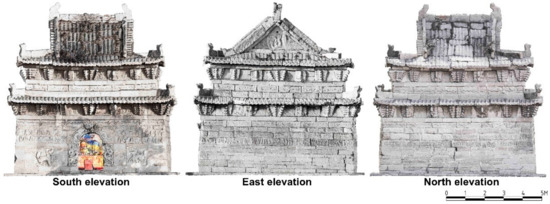
Figure 17.
Elevation diagram of the current situation of the Limestone Hall (currentstatus).
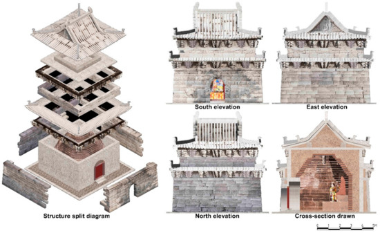
Figure 18.
Separable model, elevation diagram, and section diagram of the Limestone Hall obtained by recovery (ideal status).
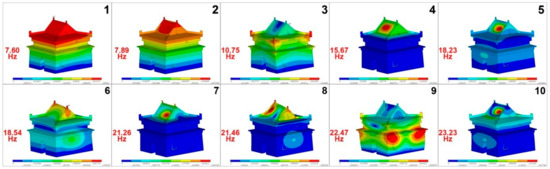
Figure 19.
The first 10-order intrinsic frequency and vibration model diagram of the Limestone Hall under ideal status.
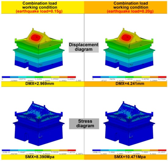
Figure 20.
Displacement diagram and stress diagram of the Limestone Hall under ideal status with earthquake accelerations of 0.15 g and 0.2 g.
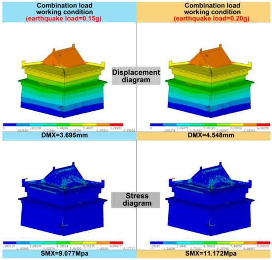
Figure 21.
Displacement diagram and stress diagram of the Limestone Hall under current status with earthquake accelerations of 0.15 g and 0.2 g.
4.2. Results Discussions
4.2.1. Model Accuracy
After comparing the 3D model with the real object of the Limestone Hall, it was found that the model accuracy was superior to 1.5 cm, which relatively realistically reflects the current situation of the Limestone Hall. It can not only be used to demonstrate and provide a virtual tour for the current situation but can also be used for disaster recording and monitoring. A separable 3D model was the model newly built after conducting regularization and idealization on the basis of the 3D model for the current situation and reflected the ideal status of the Limestone Hall. These were provided with a difference comparison, and the appearance of the sedimentation and displacement of the Limestone Hall at present can be identified and measured to provide the basis and guidance for possible repair in the future. The most important is that these two models fully revealed the unique structural practices of the Limestone Hall, and represents the great design construction idea, which is why it is necessary for the Limestone Hall to be demonstrated to the whole world.
4.2.2. Appearance and Deformation of the Limestone Hall
Through comparing the current status model and the separable model, overall, it was found that the Limestone Hall leaned towards the northwest, and the northwest corner had vertically subsided for 19.3 cm; the first-floor eave was relatively flat, and second floor eave was slightly curved (the middle was lower and two sides higher). This kind of style was designed with purpose, but there was nonuniform sedimentation in the second-floor eave, and the sedimentation heights in the maximum vertical direction for the second-floor eave on the north side and south side were 4.3 cm and 1.9 cm, respectively; in addition, there was an obvious protrusion in the north wall and the south wall, and the maximum protrusion value was 21.4 cm. The deformation analysis result coincides with the phenomenon observed on site and is more accurate.
4.2.3. Assessment for Anti-Seismic Capacity of the Limestone Hall
It can be seen from the results obtained through the finite element analysis that the scope for the first 10-order inherent frequency of the Limestone Hall at the ideal status was 7.60–22.23 Hz, and the maximum vibration mostly occurred in the middle part of the roof and occurred in the middle part of the roof and the side wall in a few cases. Under the frequency of 15.67 Hz in the 3rd order, 21.46 Hz in the 8th order, and 22.47 Hz in the 9th order, the overall damage generated by the vibration was relatively obvious.
When the earthquake force of the Hall in the ideal status was 0.15 g, the maximum displacement occurred in the middle of the second roof, and the maximum stress occurred at the joint of the vertical ridge of the second roof, with the stress value of 8.390 MPa, which was lower than the ultimate shear-resistance yield strength 10.2 MPa of the Hall, and the structure was relatively safe; when the 0.20 g acceleration was exerted, the position of the maximum displacement and the maximum stress was the same as the case of 0.15 g of the seismic force, with the maximum stress being 10.471 MPa, which slightly exceeded its ultimate shear-resistance yield strength, so the structure will be damaged.
When the seismic force was 0.15 g, the maximum displacement occurred in the middle of the second roof. The maximum stress occurred at the intersection of the vertical ridge of the second roof. The stress value was 9.077 MPa, which was close to the shear yield strength of the Limestone Hall. When the acceleration of 0.20 g was exerted, the position of the maximum displacement and maximum stress was the same as that of 0.15 g seismic force, with the maximum stress being 11.172 MPa, which was far beyond the shear yield strength and the structure was damaged as a result.
Seismic acceleration generated by the VII-degree earthquake was about 0.09–0.19 g, and the seismic acceleration of the VIII-degree earthquake was about 0.20–0.38 g.
The above analysis results showed that the maximum displacement occurred in the central position of the tabia under the roof for the Hall at the time of earthquake, and the maximum stress occurred at the connection location of the ridge. It was speculated that the total damage mode for the roof was roof collapse due to the obvious displacement and scattering of tabia. It needs to be pointed out that, as the ridge is formed by binding thin stone strips, the structure is very unstable. When the strength of the adhesive on the rocks is severely decreased due to weathering, the vertical ridge of the second roof may easily fall into separate stones due to slight vibration, but the stones proper are not damaged, which means that under the influence of a small earthquake, it is likely that the ridge will be partially scattered and destroyed before it reaches the shear yield strength of the stone. The main damage location observed in the site was exactly concentrated on the ridge of the second floor (Figure 16), which is very consistent, indicating that the credibility of the finite element simulation result was high. The Limestone Hall was affected by earthquakes twice in A.D.1709 and A.D. 1718. The epicenters were about 300–400 km far from Heyang, the local earthquake intensity in Heyang did not reach the V-degree estimated according to the vibration sense, and it was speculated that the scattering of stones in the ridge of the Limestone Hall was caused during these two earthquakes. The analysis result showed that the wall of the Limestone Hall was relatively stable at the time of the earthquake, and the wall crack seen on site was not caused by earthquake force. This could be a crack generated by stone wall squeezing after tabia in the wall absorbs water and expands.
Therefore, we can take it that the main structure of the Limestone hall is quite strong and is able to stand a VII-degree earthquake. However, its ridge is relatively fragile and cannot stand a V-degree earthquake, so it will easily fall apart.
4.2.4. Completion for Research of the Limestone Hall
Through the above discussion, it was found that the accuracy for the mapping results of the Limestone Hall was relatively high and the recovery model can be used for disaster assessment and future repair. The seismic calculation results were similar to the damage for the current situation, and the model simulation accuracy was relatively high. Both reached the expected research objective, and completion was relatively good.
5. Conclusions
In conclusion, the following conclusions were obtained:
- 1.
- Comparing architectural heritage in a multilayer structure with the general architectural heritage, the building process is more complex, and cognition is more difficult. It has unique research meaning and historical cultural value. It is feasible to use photogrammetry, three-dimensional modeling and finite element analysis to conduct seismic assessment of this kind of heritage. The precise degree of the three-dimensional model, the accurate degree of parameter measurement and estimation, the setting of component attributes in the finite element model and the strategy of finite element analysis have an important effect on the result.
- 2.
- In the case of mapping architectural heritage with a multilayer structure, adopting technical means for oblique aerial photogrammetry and ground photography measurements is effective and feasible, and can guarantee accuracy, and a model that can be used for browsing and size measurement can be generated.
- 3.
- In the case of modeling architectural heritage with a multilayer structure, it can be subjected to 3Dmax software for rebuilding after the construction procedure is clearly analyzed. Comparing the rebuilt model and the current status model, the body displacement generated in the architectural heritage can be measured, and its repair can be guided.
- 4.
- In the case of assessment for the seismic performance of architectural heritage with a multilayer structure, utilizing finite element software such as ANSYS for stimulation is feasible. In the case of the Limestone Hall, which has a five-layer structure, we think after calculation that the main body structure of the Limestone Hall can resist a VII-degree earthquake at most, and its two-layer ridge cannot resist a V-degree earthquake in the case of unstable fixation. In the future, it is necessary to re-fill the tabia missing between the outer wall and the middle wall and reinforce the ridge. The position of the Hall that is most vulnerable to deformation is the tabia layer under the roof of the second-floor in earthquake damage, and the damage mode is roof collapse caused by soil displacement and scattering. Therefore, special attention shall be paid to this position at the time of the Limestone Hall monitoring.
Author Contributions
S.C. conceived the study and wrote the paper, did the field data collection and data processing, implemented 3D modeling, and accuracy analysis; S.W. implemented the 3D rendering and provided some methods; C.L. assisted S.C. to create the mechanical model and analyzed the results; Q.H. conceived the study; and H.Y. provided some valuable advice.
Funding
The authors would like to thank “The Compass Plan” supported by the State Administration of Cultural Heritage. This research was also supported by the National Natural Science Foundation of China (Grant No. 41271452), Key Technologies R&D Program of China (Grant No. 2015BAK03B04), Major theoretical and practical research projects in the social sciences of Shaanxi Province (Grant No. 2017C024), and The Fundamental Research Funds for the Central Universities (Chang’an University) (Grant No. 310841161002).
Acknowledgments
Thanks for helping of Di Zhang.
Conflicts of Interest
The authors declare no conflict of interest.
References
- Yu, M.-H. Unified Strength Theory and Its Applications; Springer: Berlin/Heidelberg, Germany, 2004. [Google Scholar]
- Kouris, L.A.S.; Kappos, A.J. Detailed and Simplified Non-Linear Models for Timber-Framed Masonry Structures. J. Cult. Herit. 2012, 13, 47–58. [Google Scholar] [CrossRef]
- Miccoli, L.; Muller, U.; Fontana, P. Mechanical Behaviour of Earthen Materials: A Comparison Between Earth Block Masonry, Rammed Earth and Cob. Constr. Build. Mater. 2014, 61, 327–339. [Google Scholar] [CrossRef]
- Li, Y.; Li, Z.; Xu, T.J. Research of Brittle Shear Failure Strength of Rock Materials. In Applied Mechanics and Materials; Trans Tech Publications Ltd.: Durnten-Zurich, Switzerland, 2014. [Google Scholar]
- Chen, S.L.; Feng, X.T.; Zhou, H. Twin T-2 Strength Theory of Tri-Parameters and Its Application in the Rock Materials; Rinton Press, Inc.: Princeton, NI, USA, 2002. [Google Scholar]
- Milani, G.; Valente, M. Comparative Pushover and Limit Analyses on Seven Masonry Churches Damaged by the 2012 Emilia-Romagna (Italy) Seismic Events: Possibilities of Non-Linear Finite Elements Compared with Pre-Assigned Failure Mechanisms. Eng. Fail. Anal. 2015, 47, 129–161. [Google Scholar] [CrossRef]
- Carpinteri, A.; Lacidogna, G.; Invernizzi, S.; Accornero, F. The Sacred Mountain of Varallo in Italy: Seismic Risk Assessment by Acoustic Emission and Structural Numerical Models. Sci. World J. 2013. [Google Scholar] [CrossRef]
- Marques, R.; Pereira, J.M.; Lourenco, P.B.; Parker, W.; Uno, M. Study of the Seismic Behavior of the “Old Municipal Chambers” Building in Christchurch, New Zealand. J. Earthq. Eng. 2013, 17, 350–377. [Google Scholar] [CrossRef]
- Panto, B.; Cannizzaro, F.; Caddemi, S.; Calio, I. 3D Macro-Element Modelling Approach for Seismic Assessment of Historical Masonry Churches. Adv. Eng. Softw. 2016, 97, 40–59. [Google Scholar] [CrossRef]
- Fragonara, L.Z.; Boscato, G.; Ceravolo, R.; Russo, S.; Ientile, S.; Pecorelli, M.L.; Quattrone, A. Dynamic Investigation on the Mirandola Bell Tower in Post-Earthquake Scenarios. Bull. Earthq. Eng. 2017, 15, 313–337. [Google Scholar] [CrossRef]
- Formisano, A.; Florio, G.; Landolfo, R.; Mazzolani, F.M. Numerical Calibration of a Simplified Procedure for the Seismic Behaviour Assessment of Masonry Building Aggregates. In Proceedings of the 13th International Conference on Civil, Structural and Environmental Engineering Computing, Crete, Greece 6–9 September 2011. [Google Scholar]
- Maio, R.; Vicente, R.; Formisano, A.; Varum, H. Seismic vulnerability of building aggregates through hybrid and indirect assessment techniques. Bull. Earthq. Eng. 2015, 13, 2995–3014. [Google Scholar] [CrossRef]
- Formisano, A. Local- and global-scale seismic analyses of historical masonry compounds in San Pio delle Camere (L’Aquila, Italy). Nat. Hazard. 2017, 86, 465–487. [Google Scholar] [CrossRef]
- Acito, M.; Bocciarelli, M.; Chesi, C.; Milani, G. Collapse of the Clock Tower in Finale Emilia after the May 2012 Emilia Romagna Earthquake Sequence: Numerical Insight. Eng. Struct. 2014, 72, 70–91. [Google Scholar] [CrossRef]
- Faggiano, B.; Marzo, A.; Formisano, A.; Mazzolani, F.M. Innovative steel connections for the retrofit of timber floors in ancient buildings: A numerical investigation. Comput. Struct. 2009, 87, 1–13. [Google Scholar] [CrossRef]
- Fang, D.P.; Iwasaki, S.; Yu, M.H. Ancient Chinese timber architecture-II: Dynamic characteristics. J. Struct. Eng. 2001, 11, 1358–1364. [Google Scholar] [CrossRef]
- Galassi, S.; Paradiso, M. BrickWORK Software-Aided Analysis of Masonry Structures. IERI Procedia 2014, 7, 62–70. [Google Scholar] [CrossRef]
- Negulescu, C.; Ulrich, T.; Baills, A.; Seyedi, D.M. Fragility Curves for Masonry Structures Submitted to Permanent Ground Displacements and Earthquakes. Nat. Hazard. 2014, 74, 1461–1474. [Google Scholar]
- Gao, Y.; Yang, Q.; Wang, J.; Qin, J. Dynamic Performance of the Ancient Architecture of Feiyun Pavilion Under the Condition of Environmental Excitation. J. Vib. Shock. 2015, 34, 144–148. [Google Scholar]
- Clementi, F.; Pierdicca, A.; Formisano, A.; Catinari, F.; Lenci, S. Numerical model upgrading of a historical masonry building damaged during the 2016 Italian earthquakes: The case study of the Podestà palace in Montelupone (Italy). J. Civil. Struct. Health Monit. 2017, 7, 703–717. [Google Scholar] [CrossRef]
- Krstevska, L.; Tashkov, L.; Naumovski, N.; Florio, G.; Formisano, A.; Fornaro, A.; Landolfo, R. In-situ experimental testing of four historical buildings damaged during the 2009 L’Aquila earthquake. In COST ACTION C26: Urban Habitat Constructions under Catastrophic Events—Proceedings of the Final Conference; CRC press Taylor & Francis Group: Boca Raton, FL, USA, 2010; pp. 427–432. [Google Scholar]
- Tsogka, C.; Daskalakis, E.; Comanducci, G.; Ubertini, F. The Stretching Method for Vibration-Based Structural Health Monitoring of Civil Structures. Comput. Aided Civil. Infrastruct. Eng. 2017, 32, 288–303. [Google Scholar]
- Tang, Y.; Zhao, W. Triaxial Test Research on Dynamic Settlement of Ancient Architecture Foundation Soil under Frequent Earthquakes. J. Tongji Univ. 2012, 40, 1486–1490. [Google Scholar]
- Pau, A.; De Sortis, A.; Marzellotta, R.; Vestroni, F. Health Monitoring of Cultural Heritage Using Ambient and Forced Vibrations. Wit Trans. Built Environ. 2005, 82. [Google Scholar] [CrossRef]
- Ceravolo, R.; Pistone, G.; Fragonara, L.Z.; Massetto, S.; Abbiati, G. Vibration-Based Monitoring and Diagnosis of Cultural Heritage: A Methodological Discussion in Three Examples. Int. J. Archit. Herit. 2016, 10, 375–395. [Google Scholar] [CrossRef]
- Ubertini, F.; Comanducci, G.; Cavalagli, N. Vibration-Based Structural Health Monitoring of a Historic Bell-Tower Using Output-Only Measurements and Multivariate Statistical Analysis. Struct. Health Monit. 2016, 15, 438–457. [Google Scholar] [CrossRef]
- Teza, G.; Pesci, A.; Trevisani, S. Multisensor Surveys of Tall Historical Buildings in High Seismic Hazard Areas Before and During a Seismic Sequence. J. Cult. Herit. 2015, 16, 255–266. [Google Scholar] [CrossRef]
- Maohong, Y.; Oda, Y.; Dongping, F.; Junhai, Z. Advances in Structural Mechanics of Chinese Ancient Architectures. Front. Archit. Civil Eng. China 2008, 2, 1–25. [Google Scholar]
- Formisano, A.; Marzo, A. Simplified and Refined Methods for Seismic Vulnerability Assessment and Retrofitting of an Italian Cultural Heritage Masonry Building. Comput. Struct. 2017, 180, 13–26. [Google Scholar] [CrossRef]
- Pineda, M.D.; Robador, M.A. Gil-MartíSeismic damage propagation prediction in ancient masonry structures: An application in the non-linear range via numerical models. Open Constr. Build. Technol. J. 2011, 511, 71–79. [Google Scholar] [CrossRef]
- Ramaglia, G.; Lignola, G.P.; Prota, A. Collapse Analysis of Slender Masonry Barrel Vaults. Eng. Struct. 2016, 117, 86–100. [Google Scholar] [CrossRef]
- Hemeda, S.; Pitilakis, K.; Bandis, S. Geotechnical, Geophysical Investigations and Seismic Response Analysis of the Underground Tombs in Mustafa Kamil Necropolis, Alexandria, Egypt. Mediterr. Archaeol. Archaeom. 2010, 14, 187–193. [Google Scholar]
- Guo, Z.R.; Yang, Z.F. Analysis of Aseismic Mechanism of Wooden Architecture of Ancient Chinese. In Advanced Materials Research; Trans Tech Publications Ltd.: Durnten-Zurich, Switzerland, 2014. [Google Scholar]
- Li, X.; Zhao, J.; Zhang, Y.; Zhou, C. Analysis of Elasto-Plastic Dynamic Performance of Timber Frame Palace with Nine-Puffin in Qing Dynasty. Build. Struct. 2009, 39, 80–83. [Google Scholar]
- Chen, S.; Hu, Q.; Wang, S.; Yang, H. A Virtual Restoration Approach for Ancient Plank Road Using Mechanical Analysis with Precision 3D Data of Heritage Site. Remote Sens. 2016, 8, 828. [Google Scholar] [CrossRef]


© 2018 by the authors. Licensee MDPI, Basel, Switzerland. This article is an open access article distributed under the terms and conditions of the Creative Commons Attribution (CC BY) license (http://creativecommons.org/licenses/by/4.0/).