Abstract
This research focuses on vehicle Advanced Driver Assistance Systems (ADAS), with particular emphasis on Lane Keeping Assist (LKA) systems which is designed to help drivers keep a vehicle centered within its lane and reduce the risk of unintentional lane departures. These kinds of systems detect lane boundaries using computer vision algorithms applied to video data captured by a forward-facing camera and interpret this visual information to provide corrective steering inputs or driver alerts. The research investigates the performance, reliability, sustainability, and limitations of LKA systems under adverse road and environmental conditions, such as wet pavement and in the presence of degraded, partially visible, or missing horizontal road markings. Improving the reliability of lane detection and keeping systems enhances road safety, reducing traffic accidents caused by lane departures, which directly supports social sustainability. For the theoretical test, a modified road model using MATLAB software was used to simulate poor road markings and to investigate possible test outcomes. A series of field tests were conducted on multiple passenger vehicles equipped with LKA technologies to evaluate their response in real-world scenarios. The results show that it is very important to ensure high quality horizontal road markings as specified in UNECE Regulation No. 130, as lane keeping aids are not uniformly effective. Furthermore, the study highlights the need to develop more robust line detection algorithms capable of adapting to diverse road and weather conditions, thereby enhancing overall driving safety and system reliability. LKA system research supports sustainable mobility strategies promoted by international organizations—aiming to transition to safer, smarter, and less polluting transportation systems.
1. Introduction
The automotive industry is currently devoting a great deal of attention and resources to autonomous vehicles, which is why many autonomous functions are being developed and increasingly installed in production vehicles. Therefore, when purchasing new vehicles and selecting higher equipment levels or even their basic equipment, drivers often receive a cruise control system with adaptive distance control, an automatic parking system, and a horizontal marking detection system with (or without) a lane keeping function. The primary objective of systems like adaptive cruise control, automated park assist, line detection, and lane keeping assist is to enhance the comfort and safety levels of modern vehicles [1]. However, the reliable operation of these systems requires precise calibration and control, which remains one of the key factors limiting their broader deployment. Moreover, these systems must ensure accurate and dependable performance under varying road and weather conditions, as well as across different driving speeds.
The reliability of vehicle line detection and lane keeping systems is closely linked to the principles of sustainability in modern transportation. Reliable systems contribute to social sustainability by improving road safety and reducing accidents caused by unintended lane departures, which in turn decreases injuries, fatalities, and associated social costs. From an environmental perspective, consistent and accurate lane keeping enables smoother driving behavior, minimizing unnecessary braking and acceleration. This leads to improved fuel efficiency and lower greenhouse gas emissions, supporting global efforts to mitigate climate change. Furthermore, technological and economic sustainability are enhanced through increased system durability and reduced maintenance requirements, which lower resource consumption and extend the lifespan of intelligent vehicle components. Therefore, improving the reliability of lane detection and keeping systems directly supports the transition toward sustainable and intelligent mobility, aligning with international initiatives promoting safer, cleaner, and more efficient transport solutions.
Most vehicle accidents occur due to driver distraction, inattention, fatigue, or cell phone usage while driving [2,3]. In order to maximize road safety and reduce the risk to drivers, systems that perform partial traffic monitoring and perception functions are being introduced. One of these is a road marking detection system that informs the driver when they are crossing a lane boundary under different road lighting conditions [4]. As an additional feature, it should be noted that these active systems can reduce the bad habit of drivers not indicating when maneuvering [5].
Systems warn the driver about possible lane departure (Lane Departure Warning, LDW) or directly assist in keeping the vehicle in the center of the lane or at least between the side lines (Lane Keeping Assist, LKA). This reduces the likelihood of collisions due to lane departure [6]. The main advantage of these systems is that the driver can be warned before they themselves become aware of a potential hazard, thus giving the driver more time to react to the situation [5]. A more advanced function of these systems is to prevent the vehicle from leaving the lane by warning the driver or actively controlling the vehicle when approaching a lane marking [7]. At the same time, these systems contribute significantly to the active safety of the vehicle and reduce the number of accidents on the roads [8].
LDW and LKA systems are part of the Advanced Driver Assistance Systems (ADAS) group. These systems detect lane boundaries using computerized image analysis captured by a camera facing the direction of travel, which is usually mounted on the front windshield of the vehicle, next to the rear-view mirror. When LKA detects an unintentional lane departure, where the driver crosses the lane without signaling, the system actively returns the vehicle to the lane by applying a slight steering torque and/or brake control to keep the vehicle in its original lane [9].
Horizontal marking detection systems can be divided into two classes. The first class consists of systems that do not have vehicle control functions. These passive safety systems only collect information and send a warning or reminder when necessary. They are usually installed in driver assistance systems rather than in vehicles as part of autonomous vehicle control. The second class is designed with feedback, i.e., an active safety system that aims to keep the vehicle in its lane [10]. The Society of Automotive Engineers (SAE) defines SAE levels related to motor vehicles and their autonomous functions, ranging from level 0 (no driving automation) to level 5 (full driving automation) [11]. A horizontal marking detection system with support technology is therefore classified as level 2 automation [12].
According to the European Commission, from July 2022, all new vehicles and vans must be equipped with Emergency Lane Departure Warning Systems (ELDS), and existing models must be equipped with them from July 2024. The purpose of the system is to help drivers stay safely in their lane or remain within the boundaries of the road in order to avoid accidents. Commission implementing regulation (EU) 2021/646 [13] lays down technical specifications and procedures for the type-approval of vehicles with Emergency Lane Keeping Systems (ELKS) in accordance with Regulation (EU) 2019/2144 [14]. The regulation sets out requirements for testing, performance, and safety. It aims to ensure uniform standards across all European Union countries. It specifies that the system must be designed to provide as few warnings as possible and interfere as little as possible with the driver’s intended maneuvers.
The Lane Departure Warning System (LDWS) must alert the driver no later than when the vehicle deviates more than 0.3 m from the lane marking. It must operate at speeds of 65–130 km/h, under all load conditions, with a lateral deviation of 0.1–0.5 m/s—when driving straight on dry roads with clear markings that comply with United Nations Economic Commission for Europe (UNECE) No. 130 [15]. This rule also describes the requirements for the Corrective Steering Control Function (CDCF). The speed range is from 70 km/h to 130 km/h. The basic requirements for the lane following function differ slightly from those for the lane departure warning function. Additional requirements include that the system must operate at a lateral deviation of 0.2–0.5 m/s at speeds up to 100 km/h, and at a deviation of 0.2–0.3 m/s at speeds above 100 km/h, but not exceeding 130 km/h.
Horizontal marking detection is primarily processed by analyzing camera information using traditional image and computer vision algorithms. Here, traditional methods have been gradually replaced by semantic segmentation methods, such as Deep Learning [4]. Typically, horizontal road marking detection methods use image segmentation into points or lines to recognize road markings. Methods that use line segmentation of the marking image use edges or lines as the identifiable feature (segment). However, the boundaries of lane markings often become inaccurate due to external influences. However, lane marking boundaries often become inaccurate due to external influences. This can cause various problems related to the non-recognition of a lane segment, such as not distinguishing a specific marking lane from the overall image or combining several dashed lanes into one [16].
External factors limiting the effective operation of the system also include shadows from trees, road infrastructure, or vehicles, poor weather conditions, poorly painted lane markings, or uneven road surfaces [17]. Temporary occlusion plus lateral motion creates difficult short-term tracking problems. Occlusion handling remains an active research gap covering inpainting, temporal fusion, and geometric priors [18]. When detecting road edges, image noise can be a problem, so it is more common to encounter problems when detecting points than lines. Using line-based functions for band marking recognition can be more accurate than point-based methods. Reflections (sun towards the camera) and high-contrast shadows maintain a low signal-to-noise ratio, reduce the contrast of road signs, and create false edges for the recognition system; therefore, many image analysis models that have been trained on daytime scenes perform poorly at night [19]. Most datasets and methods emphasize the relatively simple geometry of highways (parallel lanes), while complex intersections, junctions, branches, sharp clothoid curves, and roadworks create topological variability that the methods do not model well enough [20]. The markings on the lanes are often covered by tire marks, which may not allow specific markings to be distinguished from the overall image or may cause several dashed lines to merge into one [16]. Embedded automotive equipment in these cases presents latency and memory limitations. Many modern networks are too complex for real-time ECUs without vehicle trimming, quantization, or specialized architectures [21].
In the event of a collision, the camera must also be relocated and recalibrated after replacing the windshield, which increases the likelihood of system malfunction (Romano et al. 2021 [22]). In addition, vehicle pitching (sudden braking/acceleration) can alter the lane projections of the monocular system and impair localization. In such cases, combining multiple sensors (LIDAR, high-precision maps) helps, but increases costs and integration complexity [23].
Furthermore, some drivers tend to switch off these systems because false warnings reduce their confidence in the systems. It is therefore important to minimize the risk of false warnings as much as possible so that only warnings that pose a real threat are issued [24].
As a result, line detection is a key function for driver assistance and autonomous vehicle perception. Modern methods, especially deep learning monocular methods, have increased accuracy in popular benchmarks, but still face persistent, safety-critical issues: environmental variability (illumination, weather, occlusion), dataset/assessment gaps, sensor and calibration limits, real-time and deployment constraints, and adversarial/edge-case robustness [20,25].
Recent research underscores that the reliability of lane detection systems under degraded or poorly visible road markings is a critical factor for the safety and robustness of modern Lane Keeping Assist and Automated Lane Keeping Systems. Elizebeth et al. [26] demonstrated, using a Systems-Theoretic Process Analysis, that environmental degradations such as rain, fog, and low illumination can significantly impair lane perception and lead to unsafe control behaviors in automated systems. Complementing this, Wang and Alhuraish [27] introduced the OpenLKA dataset—the first large-scale, open dataset emphasizing real-world driving conditions that include worn, occluded, or missing lane markings—enabling quantitative benchmarking of lane detection reliability across vehicle models. Furthermore, Lee and Wang [28] highlighted the importance of visual communication between vehicles and drivers, showing that the level of detail in lane visualization directly affects driver workload, engagement, and trust, particularly when lane boundaries are poorly visible. Together, these works emphasize that addressing degraded lane visibility is essential for advancing reliable and human-centered LKA technologies, marking a shift from controlled, idealized environments toward data-driven, safety-critical evaluations of real-world conditions.
The aim of this research is to analyze the relationship between horizontal road marking defects and the capabilities of horizontal marking recognition systems; what types of marking defects may affect the failure of these systems and cause a vehicle to leave a specific lane in critical situations. This problem is observed on long-reconstructed, high-intensity, and less-maintained road sections. The hypothesis is that a vehicle with the horizontal marking recognition system activated will become inactive when there is no longer a dividing line or a line marking the right edge in the visible section and the road continues in a curve.
2. Materials and Methods
According to the Euro NCAP association, which has been testing horizontal marking detection systems since 2015 [29], the latest 4th generation protocol specifies precise test conditions, with the test recorded by short-range and long-range radars (24 and 77 GHz), a LIDAR device, and a video camera [30].
The test track surface is dry, with a temperature between 5 °C and 40 °C, the lane width is 3.5 m or 3.7 m when measured from the outer edge of the lane marking, horizontal markings are defined in accordance with United Nations Economic Commission for Europe (UNECE) Regulation No. 130 [15]. The test vehicle must comply with all manufacturer specifications—chassis geometry, use of specified size tires with appropriate pressure, maximum level of all operating fluids. The vehicle is filled with at least 90% of the fuel tank capacity, and ballast is installed, the weight of which is obtained by subtracting the weight of the driver and testing equipment from the specified ballast weight of 200 kg. After installing the ballast, the difference in axle weight distribution must not exceed 5% of the distribution specified by the manufacturer. When a new vehicle is received, it is driven in a mixed mode to achieve a mileage of 100 km, and the braking system is tested with different braking modes. The horizontal marking detection and lane keeping systems are tested in several scenarios: with a solid road marking and a dashed road marking. The first test is performed with the safety system turned off, and the second with it turned on.
2.1. Theoretical Research Methodology
The horizontal marking detection system with lane keeping assist (version 24.2) is simulated using the MATLAB/Simulink (version 2024b) software package with an automatic steering add-on. The model consists of two main parts: Lane Keeping Assist, which controls the front steering angle of the vehicle, and the vehicle and environment system, which models the movement of the self-driving vehicle and its environment [31].
First, a safe lateral distance is set. The lane keeping function is activated and a safe lateral distance of 0–2 m is set. A lateral distance of 1 m is selected for the specific road section being simulated. Other model settings remain unchanged.
Next, the model environment is defined, i.e., the road on which the modeled vehicle will travel. A specific road section is selected, as shown in Figure 1.
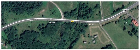
Figure 1.
Simulated road section.
After selecting a specific section, the basic data required to define the road model is collected: section length, road width, number of lanes, type and color of the lanes (Table 1).

Table 1.
The main data of the analyzed road section.
When simulating the inspection of these systems, it is necessary to take into account road defects such as unevenness and damaged road markings. Figure 2a shows severe damage to the road lane markings on the section of road under investigation, which actually disappears on the curve of the road. Therefore, these defects are taken into account in the specific simulation model.
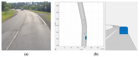
Figure 2.
Defects in horizontal lane markings: (a) actual defects of the analyzed road section, (b) defect representation in a simulation model.
The model simulates the temporary disappearance of road markings by replacing a section of road without markings. The trajectory of the vehicle is also changed—marked with a blue line (Figure 2b). When approaching and/or crossing the imaginary edge of the lane, at the moment when the vehicle is at the damaged (faded and worn) line.
2.2. Experimental Research Methodology
2.2.1. Test Equipment
The experimental research of the horizontal marking recognition system is performed using Dewesoft (Dewesoft d.o.o., Trbovlje, Slovenia; software version 2025.2) inertial navigation system (INS) designed for accurate measurement of position, orientation, velocity, and acceleration. This system uses a Kalman filter algorithm that integrates GNSS (Global Navigation Satellite System) data with MEMS (Micro-Electromechanical Systems) based inertial measurement unit information, ensuring high measurement accuracy and stability. Dewesoft NAVION i2 (Table 2) is part of a system equipped with two antennas and supports RTK (Real-Time Kinematics) technology, which allows for positioning accuracy of up to 1 cm. It is compatible with various satellite systems, such as GPS (L1, L2, L5), GLONASS (L1, L2, L3), BeiDou (B1, B2), Galileo (E1), and others. The system ensures accurate measurements even with limited GNSS signal.
Table 2.
Main Dewesoft NAVION i2 equipment technical specifications.
The device is equipped with two GNSS antennas, an interface distribution adapter, and connecting cables. The measuring device and two antennas are mounted on the outside of the vehicle, on the roof during testing (Figure 3a).
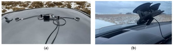
Figure 3.
Test equipment used for experimental research: (a) “NAVION i2” measuring device on the roof of a vehicle, (b) video camera on the vehicle window.
For more accurate and simpler processing of test data, a video camera is connected, which is attached to the vehicle window with a vacuum mount (Figure 3b). Using a combination of these devices, both the road section and the status of the horizontal marking system are recorded during the test.
For data processing, the equipment recorded the results at a frequency of 500 Hz. The data was exported from the measuring equipment and processed using computer programs (MATLAB and Microsoft Excel).
2.2.2. Test Section and Test Methodology
Two sections of road (540 m and 320 m long) with frequent road surface and horizontal marking defects were selected for the experimental research. Both road sections have a slight curve.
The speed limit on the test section is 70 km/h in section 1 and 90 km/h in section 2, but due to the weather conditions during the test—light snow and wet road surface—the test speed is reduced to 80 km/h (according to the vehicle speedometer).
Figure 4 shows a section of the test road, section 1, where the horizontal road marking—a continuous dividing line separating opposing traffic—is damaged. There is a risk that a vehicle with a horizontal marking recognition system activated will become inactive, as there is no longer a dividing line or a line marking the right edge in the visible section. Due to the approaching turn, this situation could be critical. The possible outcomes of the experiment are as follows:
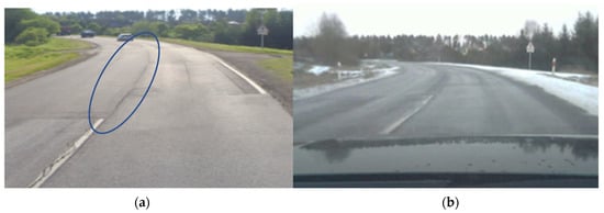
Figure 4.
Road section 1: (a) On the left side, Google Maps material, (b) Picture taken during the research.
- When driving forward in section 1, when the vehicle is fully controlled by the lane keeping system, the vehicle may cross the lane edge and drive onto the roadside if the road markings are interrupted.
- When driving back in section 1, when the vehicle is fully controlled by the lane keeping system, the vehicle may move into the opposite lane if the road markings are interrupted.
- Test drives are carried out on the agreed road sections 3–4 times in different directions, with a total of 6–8 test drives recorded on different road sections. Additional measurements are also taken to determine how the vehicle’s active safety system controls the vehicle on snow-covered roadsides and wet road surfaces.
3. Results
3.1. Theoretical Research Results
The simulation model imitates the temporary disappearance of road markings by replacing a section of road without markings. The length of the section without markings and the degree of the road curve are changed: in the first variant, the line break is 19.52 m, the curve is 9.3°, in the second variant, the line break is 20.71 m, the curve is 9.1° (Figure 5). These tests aim to determine the length of the section and the degree of the curve at which the LKA system will not detect the next line and will not perform the required maneuver.
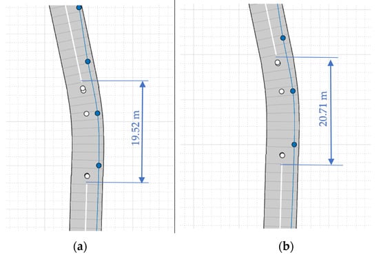
Figure 5.
Road sections: (a) line break 19.52 m, curve 9.3°; (b) line break 20.71 m, curve 9.1°.
The test begins—the speed is set at 60 km/h. The test results are presented graphically (Figure 6, Figure 7, Figure 8, Figure 9 and Figure 10).
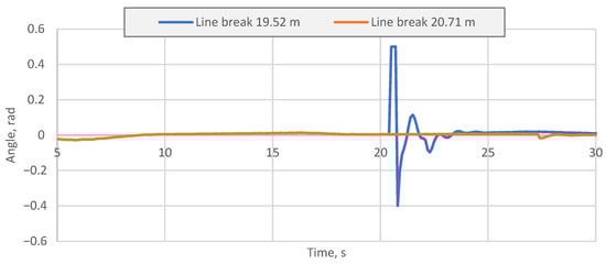
Figure 6.
Vehicle steering angle in simulation model.
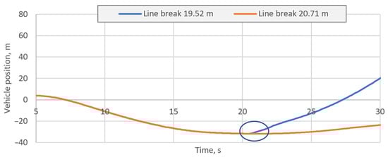
Figure 7.
Vehicle position in different tests.
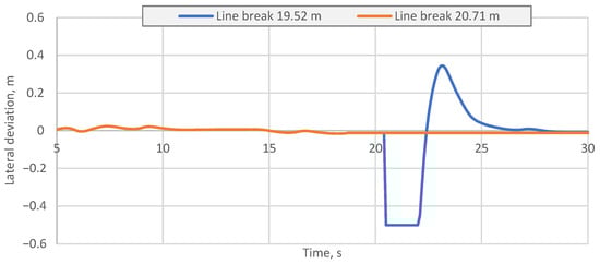
Figure 8.
Deviation of vehicle lateral deviation.
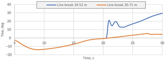
Figure 9.
Variation of vehicle yaw angle.
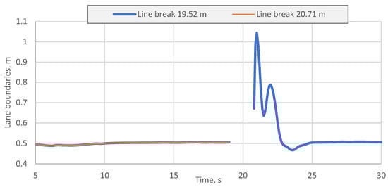
Figure 10.
Road lane boundaries.
The graph (Figure 6) shows that with a line break of 20.71 m and a road curve of 9.1°, the system does not detect the line behind the unmarked section of the road. The LKA system is not working—the vehicle’s trajectory does not match the lane (Figure 7). The vehicle with the LKA system leaves the traffic lane. According to the road curvature, the vehicle veers to the right shoulder (marked in Figure 7). If the road curve were in the other direction, the vehicle would veer into the opposite lane, resulting in a traffic accident involving other vehicles. The blue curve (Figure 6) reflects the steering angle when the system controls the vehicle—the steering angle is between—0.4 and 0.5 rad.
At the point where the horizontal markings end, the vehicle maneuvers within the lane. The lateral deviation on the road section of the road ranges from −0.5 m to 0.37 m, while the section of the road with a break line is 19.52 m (Figure 8). Once the cameras recognize the line ahead, the lateral deviation decreases.
When analyzing the vehicle’s yaw, the LKA system’s maneuver can be seen (Figure 9) when a line behind the break is detected. At 21 s the yaw increases to 20.1°. After the LKA system centers the vehicle in the lane, the vehicle continues to travel in the center of lane.
As we can see in the graph (Figure 10), at 19 s the direction of the vehicle is such that the camera does not capture the center line of the road, but at 20.8 s the line is captured. The direction of the vehicle’s movement is not smooth and only stabilizes completely at 24.8 s.
In summary, it can be stated that the described model is effective and reflects the operation of the LKA system. This research part allowed theoretically verify and confirm that typical LKA systems lose their reliable operation on a road curve with a 20 m length of horizontal marking defect. After conducting the test, it was found that with a 19.52 m line break and a 9.3° road bend, the system copes well—the cameras detect the lines after the line break and perform the necessary maneuvers to keep the vehicle in the lane. During theoretical tests, when a road section with a 20.71 m line break and a 9.1° road curve was designed, the cameras on the vehicle were unable to detect the road lines after the line break. The vehicle moves towards the right-hand curb and leaves the road. With a curve in the opposite direction or when simulating a vehicle driving from the opposite direction, the vehicle would veer into the opposite lane. This proves that the effectiveness of the LKA system depends on the quality of the designed road section and horizontal markings.
3.2. Experimental Research Results
Experimental tests on real roads with defective horizontal marking lines have shown that activated LKA systems do not ensure the same level of reliability when driving under the same conditions. Test drives with three different vehicles, repeated three to four times on the same road section, show sporadic cases where the lane keeping system fails to recognize the road markings and the driver has to take sudden action to correct the vehicle’s trajectory. The spread of results is visible according to the vehicle’s lateral acceleration, whereas individual acceleration peaks correspond to the driver’s actions when the lane keeping system unexpectedly loses control (Figure 11). Relatively large acceleration peaks were obtained due to specially selected test conditions, when the road surface was wet and there was snow on the roadside (Figure 4b).
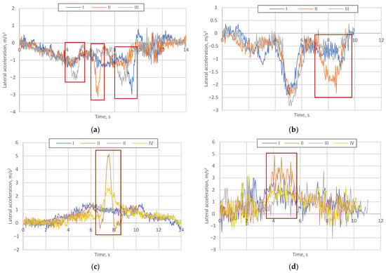
Figure 11.
(a–d) Lateral acceleration of cornering vehicle with lane keeping control active on poor road condition (data from three–four real road tests).
In order to generalize the presented characteristics of lateral acceleration and its variation, the values of skewness and kurtosis were determined. Skewness and kurtosis are statistical measures that describe the shape of a data distribution which for this case corresponds with detected inconsistencies in lane support and jumps in the acceleration. These results in the same order as Figure 11 are presented in Table 3. Distinctive peaks in the acceleration curves, indicating failures in the lane support system, are visible in jumps in the skewness and kurtosis values. This is particularly evident in variant (c), where the second case clearly stands out.
Table 3.
Skewness and kurtosis values obtained from lateral acceleration data on poor road.
As can be seen from the observed lateral acceleration peaks, a vehicle equipped with an LKA system behaves differently even under the same driving conditions, i.e., in one or two out of four driving scenarios, the reliability of the system is impaired. This is most dangerous in terms of the driver’s confidence in the system, because even though it requires the driver to keep their hands on the wheel (according to the current operation of lane support systems), in some cases the driver feels that the vehicle is reliably supported in the lane, and too often this support is lost.
Under more favorable driving conditions (dry and clean road surface), lower lateral acceleration peaks were recorded on the same road sections (again due to driver corrections), but isolated malfunctions of the LKA system were still detected (Figure 12).
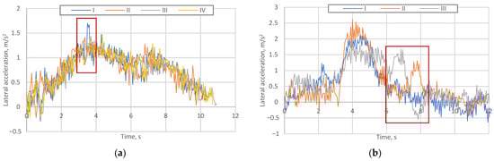
Figure 12.
(a,b) Lateral acceleration of cornering vehicle with lane keeping control active on good road condition (data from three to four real road tests).
The same skewness and kurtosis values is presented for lateral acceleration data from experimental tests on good road conditions. These numerical values of a shape of data distribution in the same order as Figure 12 are shown in Table 4.
Table 4.
Skewness and kurtosis values obtained from lateral acceleration data on good road.
During field tests conducted in accordance with the EuroNCAP test protocol, when driving on a straight section of road and allowing the vehicle to approach horizontal markings at a transverse speed of 0.6–1.0 m/s, it was found that the LKA systems of all three tested vehicles detected the approaching lane in time. The EuroNCAP protocol specifies that when the systems return the vehicle to the lane center, the lateral acceleration must not exceed 1.0 m/s2, which is confirmed by the typical lateral acceleration characteristics obtained from measurements when the LKA system returns from the right and left sides (Figure 13).
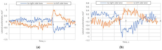
Figure 13.
(a,b) Lateral acceleration of cornering vehicle with lane keeping control active on good road condition.
Despite the similar effectiveness of the LKA system in vehicles from different manufacturers (of similar production years and system generations), the systems performed quite unpredictably on a curved road with defective horizontal markings, with 1–2 test drives (out of four) resulted in uncontrolled lane keeping. Increased lateral acceleration due to sudden driver intervention leads to a higher level of driving stress and a decrease in trust in ADAS systems. Meanwhile, on a straight road with sufficiently high-quality lane markings, the LKA systems of all vehicles reacted in a timely and proactive response to the approach of the lane edge.
4. Conclusions
To perform the theoretical test, a road model was created for a specific section, simulating the temporary disappearance of road markings. The described model is effective when the driver approaches the set critical lane boundary, and then the auxiliary lane support system returns the vehicle to its original trajectory. However, when lane lines are unclear or otherwise damaged, there is an increased possibility that the vehicle will not be returned to its original position at a critical moment.
Experimental investigations demonstrated that the performance and reliability of Lane Keeping Assist (LKA) systems are notably affected by road surface conditions and the quality of horizontal markings. Under degraded marking visibility or adverse weather conditions, the systems exhibited inconsistent lane recognition and partial loss of control, necessitating corrective driver intervention.
Analysis of lateral acceleration data revealed distinct peaks corresponding to sudden manual corrections, indicating that unexpected LKA disengagements increase the driver’s workload and may negatively influence trust in Advanced Driver Assistance Systems (ADAS).
This study contributes novel insights by combining both theoretical modeling and practical experiments to assess LKA system performance under realistic scenarios of road marking degradation. Unlike previous research, which often focuses on idealized conditions or simulations alone, the present work captures the dynamic interactions between driver behavior, system intervention, and environmental factors. Additionally, the integration of lateral acceleration data analysis provides a quantitative assessment of driver workload and system reliability, offering a new perspective on the practical limitations of ADAS technologies.
Conversely, tests conducted under favorable conditions—characterized by dry and clearly marked road surfaces—confirmed that all examined LKA systems maintained stable lane positioning and complied with EuroNCAP performance criteria, thereby highlighting the strong dependence of system reliability on environmental and infrastructural factors.
Based on theoretical and practical tests, it is important to further investigate the identified examples of safety system ineffectiveness. When improving systems, more attention should be paid to accurate warnings about possible system inactivity, thus warning the driver in time so that the driver is ready to take control at a critical moment, as seen in one of the tests when the system is unable to keep the vehicle in the lane but it did alert the driver properly (with visual, audible, and vibrating signals) and activated a short emergency braking maneuver before the dangerous section of the road. Additionally, consistent maintenance of horizontal road markings, in accordance with UNECE Regulation No. 130, remains a key factor in improving both road safety and driving comfort.
Future research plans include investigating the integration of LKA systems with additional sensor types (e.g., LiDAR, thermal cameras) to improve performance in poor visibility conditions, as well as the development of adaptive algorithms capable of learning in real time from driver behavior and road surface variability. Long-term studies could also assess the long-term impact of repeated system interventions on driver confidence and overall traffic safety, providing further guidance for the development of next-generation ADAS technologies.
Overall, vehicle safety systems, including lane departure warning and lane keep assist systems, contribute significantly to reducing road accidents, which in general improves the quality of life. By reducing the extent of vehicle damage, these ADAS systems contribute to transport sustainability, making the improvement of active safety systems important in socio-economic terms.
Author Contributions
Conceptualization, V.S. and V.Ž.; methodology, V.Ž.; software, V.S.; validation, V.S., V.Ž. and T.T.; formal analysis, V.Ž. and T.T.; investigation, V.S. and T.T.; resources, V.S. and T.T.; data curation, V.S.; writing—original draft preparation, V.S. and T.T.; writing—review and editing, V.Ž.; visualization, V.S.; supervision, V.Ž.; project administration, V.S.; funding acquisition, V.Ž. All authors have read and agreed to the published version of the manuscript.
Funding
This research received no external funding.
Institutional Review Board Statement
Not applicable.
Informed Consent Statement
Not applicable.
Data Availability Statement
The original contributions presented in the study are included in this article; further inquiries can be directed to the corresponding authors.
Conflicts of Interest
The authors declare no conflicts of interest.
Abbreviations
The following abbreviations are used in this manuscript:
| LKA | Lane Keeping Assist |
| LDW | Line Departure Warning |
| ADAS | Advanced Driver Assistance Systems |
| ELDS | Emergency Line Departure Warning Systems |
| ELKS | Emergency Lane Keeping Systems |
| SAE | The Society of Automotive Engineers |
| CDCF | Corrective Steering Control Function |
| LIDAR | Light Detection and Ranging |
| EuroNCAP | The European New Car Assessment Programme |
| UNECE | United Nations Economic Commission for Europe |
| ECU | Electronic Control Unit |
References
- Beglerovic, H.; Schloemicher, T.; Metzner, S.; Horn, M. Deep Learning Applied to Scenario Classification for Lane-Keep-Assist Systems. Appl. Sci. 2018, 8, 2590. [Google Scholar] [CrossRef]
- Peng, J.; Ren, C.; Yang, X.; Yuan, H.; Zhang, L. Detecting Driver Cognitive Distraction in Lane-Change Behavior: Multi-Source Indicators from Intention and Execution Phases. Transp. Res. Part F Traffic Psychol. Behav. 2025, 115, 103343. [Google Scholar] [CrossRef]
- Žuraulis, V.; Nagurnas, S.; Pečeliūnas, R.; Pumputis, V.; Skačkauskas, P. The Analysis of Drivers’ Reaction Time Using Cell Phone in the Case of Vehicle Stabilization Task. Int. J. Occup. Med. Environ. Health 2018, 31, 633–648. [Google Scholar] [CrossRef]
- Babić, D.; Babić, D.; Fiolić, M.; Eichberger, A.; Magosi, Z.F. A Comparison of Lane Marking Detection Quality and View Range between Daytime and Night-Time Conditions by Machine Vision. Energies 2021, 14, 4666. [Google Scholar] [CrossRef]
- Chen, W.; Wang, W.; Wang, K.; Li, Z.; Li, H.; Liu, S. Lane Departure Warning Systems and Lane Line Detection Methods Based on Image Processing and Semantic Segmentation: A Review. J. Traffic Transp. Eng. Engl. Ed. 2020, 7, 748–774. [Google Scholar] [CrossRef]
- Wang, W.; Zhao, D. Evaluation of Lane Departure Correction Systems Using a Regenerative Stochastic Driver Model. IEEE Trans. Intell. Veh. 2017, 2, 221–232. [Google Scholar] [CrossRef]
- Gamal, I.; Badawy, A.; Al-Habal, A.M.W.; Adawy, M.E.K.; Khalil, K.K.; El-Moursy, M.A.; Khattab, A. A Robust, Real-Time and Calibration-Free Lane Departure Warning System. Microprocess. Microsyst. 2019, 71, 102874. [Google Scholar] [CrossRef]
- Barickman, F.S.; Smith, L.; Jones, R. Lane Departure Warning System Research and Test Development. In Proceedings of the 20th International Conference on the Enhanced Safety of Vehicles, Lyon, France, 18–21 June 2007. [Google Scholar]
- Nguyen, B.; Famiglietti, N.; Khan, O.; Hoang, R.; Siddiqui, O.; Landerville, J. Testing and Analysis of Lane Departure Warning and Lane Keeping Assist System Response. SAE Int. J. Adv. Curr. Prac. Mobil. 2021, 3, 2301–2316. [Google Scholar] [CrossRef]
- Em, P.P.; Hossen, J.; Fitrian, I.; Wong, E.K. Vision-Based Lane Departure Warning Framework. Heliyon 2019, 5, e02169. [Google Scholar] [CrossRef] [PubMed]
- Quality, Testing and Safety; Automated and Autonomous Systems. Taxonomy and Definitions for Terms Related to Driving Automation Systems for On-Road Motor Vehicles 2018; SAE International: Warrendale, PA, USA, 2018. [Google Scholar]
- Lee, S.-H.; Lee, S.-B. Test Evaluation Method for Lane Keeping Assistance System Using Dual Cameras. Machines 2021, 9, 310. [Google Scholar] [CrossRef]
- Vehicle Safety: Type-Approval of Cars and Vans with Emergency Lane-Keeping Systems (ELKS) 2021. Available online: https://eur-lex.europa.eu/eli/reg_impl/2021/646/oj/eng (accessed on 12 November 2025).
- European Union. Regulation (EU) 2019/2144 of the European Parliament and of the Council of 27 November 2019 on Type-Approval Requirements for Motor Vehicles and Their Trailers, and Systems, Components and Separate Technical Units Intended for Such Vehicles, as Regards Their General Safety and the Protection of Vehicle Occupants and Vulnerable Road Users 2019; European Union: Bruxelles, Belgium, 2019. [Google Scholar]
- European Union. Regulation No. 130 of the Economic Commission for Europe of the United Nations (UN/ECE)—Uniform Provisions Concerning the Approval of Motor Vehicles with Regard to the Lane Departure Warning System (LDWS) 2014; European Union: Bruxelles, Belgium, 2019. [Google Scholar]
- Yoo, J.; Kim, D. Graph Model-Based Lane-Marking Feature Extraction for Lane Detection. Sensors 2021, 21, 4428. [Google Scholar] [CrossRef]
- Ye, Y.Y.; Hao, X.L.; Chen, H.J. Lane Detection Method Based on Lane Structural Analysis and CNNs. IET Intell. Trans. Sys. 2018, 12, 513–520. [Google Scholar] [CrossRef]
- Agrawal, A.; Sivakumar, A.J.; Kaif, I.; Banerjee, C. LOID: Lane Occlusion Inpainting and Detection for Enhanced Autonomous Driving Systems. Mach. Vis. Appl. 2025, 36, 120. [Google Scholar] [CrossRef]
- Long, J.; Yan, Z.; Peng, L.; Li, T. The Geometric Attention-Aware Network for Lane Detection in Complex Road Scenes. PLoS ONE 2021, 16, e0254521. [Google Scholar] [CrossRef] [PubMed]
- Waykole, S.; Shiwakoti, N.; Stasinopoulos, P. Review on Lane Detection and Tracking Algorithms of Advanced Driver Assistance System. Sustainability 2021, 13, 11417. [Google Scholar] [CrossRef]
- Nie, S.; Zhang, G.; Yun, L.; Liu, S. A Faster and Lightweight Lane Detection Method in Complex Scenarios. Electronics 2024, 13, 2486. [Google Scholar] [CrossRef]
- Romano, R.; Maggi, D.; Hirose, T.; Broadhead, Z.; Carsten, O. Impact of lane keeping assist system camera misalignment on driver behavior. J. Intell. Transp. Syst. 2021, 25, 157–169. [Google Scholar] [CrossRef]
- Gamerdinger, J.; Teufel, S.; Bringmann, O. Datasets for Lane Detection in Autonomous Driving: A Comprehensive Review 2025. arXiv 2025, arXiv:2504.08540. [Google Scholar] [CrossRef]
- Navarro, J.; Deniel, J.; Yousfi, E.; Jallais, C.; Bueno, M.; Fort, A. Influence of Lane Departure Warnings Onset and Reliability on Car Drivers’ Behaviors. Appl. Ergon. 2017, 59, 123–131. [Google Scholar] [CrossRef]
- Iqbal, M.; Han, J.C.; Zhou, Z.Q.; Towey, D.; Chen, T.Y. Metamorphic Testing of Advanced Driver-Assistance System (ADAS) Simulation Platforms: Lane Keeping Assist System (LKAS) Case Studies. Inf. Softw. Technol. 2023, 155, 107104. [Google Scholar] [CrossRef]
- Elizebeth, M.J.; Khastgir, S.; Jennings, P. Hazard Analysis of an Automated Lane Keeping System Using Systems-Theoretic Process Analysis. Accid. Anal. Prev. 2025, 221, 108171. [Google Scholar] [CrossRef] [PubMed]
- Wang, Y.; Alhuraish, A.; Yuan, S.; Zhou, H. OpenLKA: An Open Dataset of Lane Keeping Assist from Recent Car Models under Real-World Driving Conditions. arXiv 2025, arXiv:2505.09092. [Google Scholar] [CrossRef]
- Lee, Y.C.; Wang, J. Human Impact of Visual Detail in Vehicle Lane-Keeping System Communication. IFAC-PapersOnLine 2025, 59, 19–24. [Google Scholar] [CrossRef]
- Re, F.; Kriston, A.; Broggi, D.; Minarini, F. Testing the Robustness of Commercial Lane Departure Warning Systems. Transp. Res. Rec. J. Transp. Res. Board 2021, 2675, 385–400. [Google Scholar] [CrossRef]
- European New Car Assessment Programme: Test Protocol—Lane Support Systems; EuroNCAP: Brussels, Belgium, 2022.
- Lane Keeping Assist System: Simulate Lane-Keeping Assistance Using Adaptive Model Predictive Controller; MATLAB Help Center: Natick, MA, USA, 2018.


Disclaimer/Publisher’s Note: The statements, opinions and data contained in all publications are solely those of the individual author(s) and contributor(s) and not of MDPI and/or the editor(s). MDPI and/or the editor(s) disclaim responsibility for any injury to people or property resulting from any ideas, methods, instructions or products referred to in the content. |
© 2025 by the authors. Licensee MDPI, Basel, Switzerland. This article is an open access article distributed under the terms and conditions of the Creative Commons Attribution (CC BY) license (https://creativecommons.org/licenses/by/4.0/).