Abstract
The sustainable rehabilitation of existing buildings is essential to achieve urban resilience, resource efficiency and seismic risk reduction. This study investigates an integrated retrofit strategy that combines vertical extension with inter-story isolation to simultaneously enhance seismic performance and energy efficiency, creating additional usable space without additional land consumption. The inter-story isolation mechanism reduces seismic demand by decoupling a new and existing structure and introducing beneficial damping effects, whereas vertical extension improves a building’s envelope to reduce energy demands for heating and cooling. A tailored design methodology for integrated intervention is presented, according to which, for the structural part, a two-degrees-of-freedom dynamic model is adopted to design the characteristics of the isolation layer. The methodology is applied to a case-study building located in L’Aquila, Italy, where two alternative vertical extensions, one rigid and one lightweight, are analyzed. Time-history analyses and energy simulations for annual primary energy demand are carried out to assess the structural and thermal performance of the integrated retrofit. The results indicate that the proposed solution can reduce top-floor acceleration by up to 35%, inter-story drift by 30–35%, base shear by over 30% and primary energy demand by 11%, demonstrating its effectiveness in improving both seismic safety and energy performance. The main novelty of this study lies in the systematic integration of inter-story isolation with building envelope enhancement through vertical extension, offering a unified design framework that merges structural and energy retrofitting objectives into a single sustainable intervention.
1. Introduction
The sustainable rehabilitation of existing buildings is a growing priority in the context of urban resilience, resource efficiency and seismic risk mitigation. As urban areas face increasing densification and land scarcity, the preservation and performance improvement of the existing building stock has become essential. Among the strategies proposed for urban densification, vertical additions represent an effective alternative to demolition, as they allow reusing the existing structural stock while increasing its functional capacity [1]. This strategy is being increasingly adopted in major cities such as London, Milan, Tokyo and Barcelona as a sustainable alternative to demolition and reconstruction, in line with circular economy principles [2].
In seismic areas, vertical enlargement can be conceived as an opportunity to couple structural upgrading and spatial densification. In particular, the use of an inter-story isolation system (IIS), i.e., a seismic isolation layer positioned between an existing building and newly added stories, represents a promising solution to decouple the seismic response of the two structural components. Properly designed, an IIS can reduce the seismic demand on an existing structure, thereby enhancing its performance during earthquakes [3,4]. This makes it possible to add new stories without increasing, and potentially while reducing, the vulnerability of the original structure. A primary consideration in the structural design of vertical extensions is the assessment of the existing structure’s adequacy to support the additional loads. For masonry buildings, their inherent over-strength for gravity loads can make them suitable candidates for vertical addition, although seismic retrofitting is often necessary [2]. Uncertainties regarding the material properties, design details and current condition of existing structures, particularly foundations, necessitate a careful assessment, potentially involving tests and numerical analysis [5]. Moreover, the choice of structural material and a system for the vertical extension are crucial design decisions, often influenced by the load-bearing capacity of the existing structure, the need for rapid and efficient construction in urban environments, and sustainability considerations. Recent research works [1,6,7] highlight the potential to reduce the additional load on existing buildings by using lightweight construction materials such as steel and timber.
From a structural perspective, vertical extension with an IIS combines two passive control mechanisms: seismic isolation and tuned mass damping. An IIS modifies a system’s dynamic behavior by acting as a filter for seismic energy, while a vertical extension itself can function as a tuned mass, providing beneficial damping effects for the existing building [8]. Specifically, the added mass oscillating out of phase with the existing structure dissipates part of the input energy through the IIS and internal damping of the upper structure. These combined effects introduce complex dynamic interactions, including possible significant contributions from higher vibration modes, which must be carefully considered in the design process [9].
The following are crucial aspects of the design of a vertical extension with an IIS: the typical design variables, namely, the mass and the stiffness of the vertical extension, together with the stiffness and damping properties of the IIS. Specifically, such properties can vary depending on the dynamic characteristics of the designed vertical extension, and they are also related to the substructure dynamic characteristics. In the literature, the mechanical modeling of such systems typically follows two approaches. The first, based on the mass damping concept, uses a two-degrees-of-freedom (2-DOF) model, where the upper structure is considered rigid and all relative motion is concentrated in the isolators [10,11,12]. The second, grounded in isolation theory, employs a 3-DOF model to account for global building effects and mode coupling between the original and added structure [9,13]. The choice between these models depends on the relative stiffness, mass and dynamic interaction of the two structural components.
From an energy efficiency standpoint, the vertical extension of existing buildings can also contribute to energy efficiency goals. It is recognized as a cost-effective strategy to improve performance and reduce environmental impact, particularly in medium-density urban contexts [14]. While the extensive transformation of housing estates in post-socialist cities has been the focus of numerous studies [15], the vertical extension paradigm can be effectively applied beyond this specific context, offering opportunities in a broad range of urban environments. A variety of construction technologies, ranging from traditional masonry systems to advanced timber and glass modular solutions [16], can be considered for implementing vertical extensions on residential buildings. Although the addition of new floors inevitably leads to an increase in total heating and cooling demand due to the larger volume, current Italian regulations require that the newly constructed portion complies with contemporary energy standards, which are calibrated based on climatic zones. Since these standards mandate high thermal performance for building envelopes, the added volume often exhibits significantly better insulation than the existing structure. As a result, the vertical extension may contribute to a reduction in the specific primary energy consumption for heating and cooling, not only for the building as a whole but also for the pre-existing portion. Moreover, vertical extensions can also positively influence the surrounding microclimate, further enhancing the sustainability of the intervention [15].
The adoption of multi-functional, lightweight prefabricated façades has been proposed as an effective strategy for the energy refurbishment of existing buildings, demonstrating particular suitability for specific building typologies [17]. This approach aligns with the need for adaptable solutions in the face of evolving climatic conditions. Notably, climate change is exerting a significant impact on Italy, prompting considerations for substantial revisions to building regulations to address future climate scenarios [18]. Consequently, there is an anticipated shift towards refurbishment and extension methodologies that balance the demand for new residential spaces, minimize land use and enhance energy performance. While previous research has addressed vertical extension from either a structural or an energy perspective, its potential as an integrated seismic and energy retrofit strategy remains underexplored. This lack of integration can be attributed to the discipline-specific nature of previous studies: investigations on inter-story isolation have primarily aimed at seismic demand reduction and dynamic response control, without considering the associated changes in energy behavior. Conversely, works focusing on vertical extensions or façade retrofits have prioritized thermal performance and envelope design, overlooking their interaction with the structural system. Consequently, the cross-disciplinary benefits and design challenges of combining inter-story isolation with energy-efficient vertical additions have yet to be clarified.
In recent years, increasing attention has been devoted to integrated retrofit strategies that simultaneously address seismic and energy performance. Full-scale experimental campaigns have demonstrated the feasibility of coupling structural strengthening with envelope upgrading, for instance through textile-reinforced mortar combined with thermal insulation [19], or through cross-laminated timber retrofits validated by pseudo dynamic tests [20]. A broader critical review has also highlighted the challenges and opportunities of seismic-energy integrated retrofits, stressing the need for multi-criteria approaches [21]. Complementary to these application-oriented studies, recent reviews have framed seismic resilience enhancement in buildings [22], vibration suppression technologies such as tuned mass dampers [23], and advanced structural control strategies for tall buildings [24]. Within this wider context, vertical extension with inter-story isolation can be positioned as a promising but still uninvestigated solution.
This paper proposes an exploratory study investigating vertical extension with an IIS as a unified solution to simultaneously reduce seismic vulnerability and improve energy performance in existing buildings. The key innovation of the study lies in proposing and assessing vertical extension with IIS as an integrated retrofit solution. The research delivers a design methodology that simultaneously addresses structural and energy efficiency objectives in a whole intervention, in line with the principles of sustainable development [25]. The main objectives of the study are to furnish a methodology to design a vertical extension with IIS that is able to improve both the seismic and energy efficiency of an original building and to assess the effectiveness of the integrated intervention compared to the existing building’s performance under seismic and climatic conditions. The vertical extension is designed to meet current regulatory standards for both structural safety [26] and energy performance [27]. High-damping rubber bearings are adopted for the IIS, while the upper structure is designed to act as a large mass-tuned mass damper. A simplified 2-DOF model is employed, in line with the damping-based approach proposed by Reggio and De Angelis [10], and it is adapted here for a realistic vertical extension case. Two alternative design configurations are investigated: The first adheres strictly to the assumptions of linear base isolation theory, treating the upper structure as a rigid body. The second explores a lighter, more flexible upper structure aligned with sustainable construction practices, relaxing the aforementioned assumptions. The dual aim is to (i) test the limits of the rigid-body assumption in realistic design scenarios and (ii) assess whether a lighter extension can still deliver effective seismic performance when designed using the same 2-DOF model.
The methodology is applied to a case study involving a reinforced concrete building located in L’Aquila, Italy. Seismic time-history analyses and energy simulations are conducted to evaluate structural response and energy behavior, using appropriate performance metrics to quantify the benefits of the integrated retrofit.
The remainder of the paper is structured as follows. Section 2 describes the proposed strategy and design methodology based on vertical extension and IIS as an integrated approach to combine seismic and energy retrofitting. Section 3 details the design process of the integrated intervention. In Section 4, the methodology is applied to a case-study structure to assess its effectiveness. Finally, Section 5 presents the conclusions of the study.
2. Definition of the Integrated Retrofit Strategy and Design Methodology
The study proposes an integrated retrofit strategy that simultaneously combines seismic and energy upgrading through the addition of a vertical extension structurally decoupled from the existing building by an IIS. To contextualize this strategy within the state of the art, several benchmark studies addressing combined interventions for existing buildings which include both seismic and energy performance in the retrofit can be cited (see, for instance, refs. [28,29,30]). However, the solutions adopted in these studies differ from the one proposed here, both in terms of retrofit typology and analytical methodology. Consequently, a direct comparison of the results in terms of overall effectiveness is not straightforward.
The advantages of the proposed intervention are the exploitation of the IIS mechanism to reduce the seismic demand of existing buildings, to improve the energy performance of the original building envelope through the thermal insulating effect of the new upper volume and to increase the usable floor area without consuming additional land, contributing to urban densification in a sustainable manner. A key assumption of the intervention is that the vertical extension is designed in full compliance with current structural and energy standards; see, specifically, ref. [26] for seismic performance and ref. [27] for thermal efficiency. The new addition is conceived using lightweight, high-performance materials and construction systems that meet modern seismic resistance and thermal insulation requirements. Considering the structural limitations typical of existing buildings, the vertical extension is conservatively limited to a single additional story. This conservative design choice avoids overstressing existing foundations and load-bearing elements, ensuring structural compatibility without the need for extensive retrofitting of the substructure. Engineering practice confirms that limiting the addition to one lightweight floor often allows for effective upgrading within the reserve capacity of the original building, thus maintaining safety while limiting intervention costs.
Building upon previous frameworks for combined structural-energy retrofits, the present study adapts the methodology proposed in ref. [31] to the specific case of a vertical extension with an IIS as an integrated retrofit strategy. The proposed workflow, summarized in the flowchart of Figure 1, comprises five main steps, which are outlined below.
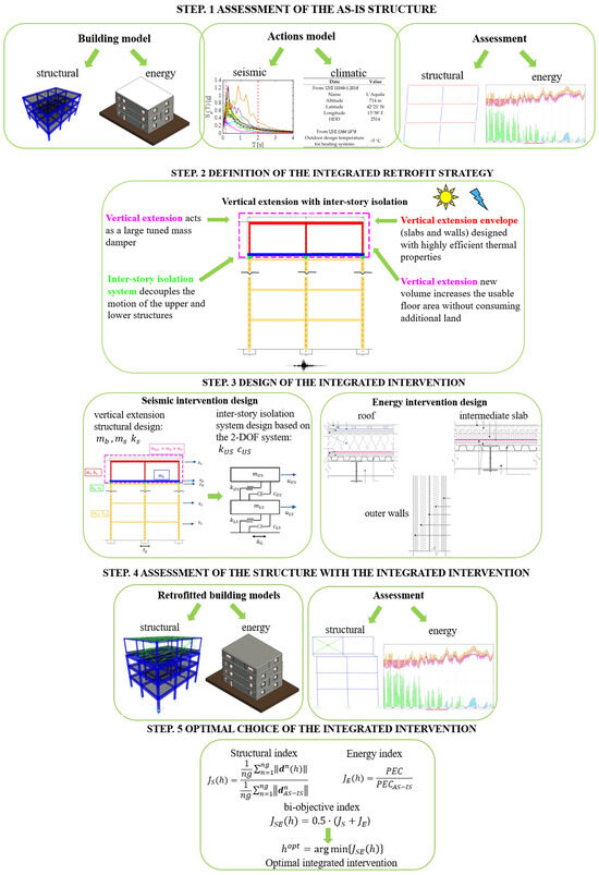
Figure 1.
Flowchart of the methodology to design the integrated retrofit strategy [32,33].
Step 1: Assessment of the AS-IS structure. The methodology starts by defining suitable models of the AS-IS building for structural and energy analysis. It follows the definition of the actions—earthquake and climate—applied to the building and the models adopted. Finally, the assessment of the building is carried out to quantify the seismic vulnerability and characterize the thermal performance and energy demand.
Step 2: Definition of the integrated retrofit strategy. The retrofit intervention includes the selection of construction materials and structural frame for the vertical extension, the properties of seismic isolators and the energy-efficient design of the added envelope in compliance with current energy codes.
Step 3: Design of the integrated intervention. Seismic and energy designs of the integrated interventions are conducted in parallel based on current national standards for structural safety [26] and energy performance [27]. The vertical extension is dimensioned to function as a tuned mass, while the IIS is designed to optimize damping and stiffness for input energy dissipation. The energy design ensures the thermal efficiency of the new volume and its positive impact on the overall building performance.
Step 4: Assessment of the structure with the integrated intervention. Once the models of the retrofitted structure for the integrated intervention have been defined, structural and energy analyses are carried out, and the effectiveness is evaluated by comparing the performance of the retrofitted building with the original one. Seismic performance is assessed through modal and dynamic time-history analyses, while energy behavior is evaluated through dynamic simulations of heating and cooling demand.
Step 5: Optimal choice of the integrated intervention. Performance metrics are used to quantify the reached improvements. In this final step, possible alternative retrofit configurations exploited in the design of the integrated intervention can be evaluated based on a bi-objective performance function combining seismic and energy indicators. The goal is to identify the most effective integrated solution, balancing structural resilience and energy efficiency.
3. Design of the Integrated Intervention
3.1. Seismic Retrofit Design
Consider an existing building, indicated in the following as the lower structure (LS), modelled as an N-DOF multi-degrees-of-freedom structure with a lumped mass, linear stiffness and damping subjected to seismic input .
The equations of motion for the structure are written as
where the vector is the relative displacement of the lower structure; and are the mass, damping and stiffness matrices, respectively, which have the generic components , with i = 1–N; and is the unit influence vector. In order to reduce the dynamic response of the N-DOF structure it is assumed to add a vertical extension on the top of the existing building connected by means of a flexible and dissipative layer, i.e., the IIS, with an overall stiffness and damping . The vertical extension is modeled with a base mass, , that moves horizontally with relative displacement and a superstructure mass, , that moves horizontally with relative displacement , connected together with an elastic stiffness, , and damping coefficient, . The vertical extension represents the upper structure (US) connected to the lower structure with the IIS (Figure 2a).
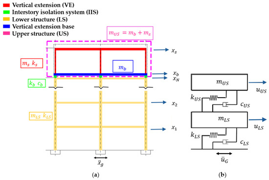
Figure 2.
(a) (N + 2)-DOF structure; (b) reduced 2-DOF system.
The overall (N + 2)-DOF system’s equations of motion are
where = is the relative displacement vector; is the unit influence vector; and the mass (), damping () and stiffness () matrices have dimensions and are defined as
For the purpose of designing the IIS, having assumed the addition of a limited number of stories in the vertical extension (in this study it is assumed that one story will be added) or the design of a sufficiently rigid upper structure with respect to the stiffness of the isolation layer, it is possible to simplify the behavior of the (N + 2)-DOF structure by adopting a reduced 2-DOF system, representing the lower structure, the IIS and the upper structure (Figure 2b), where the IIS is modelled with a viscous elastic connection, with a linear spring and viscous damper arranged in parallel (Kelvin–Voigt model) exerting a force, . By following reduction order model standard techniques [34], the displacement of the N-DOF lower structure can be approximated to a single generalized displacement, , through a shape function, , and can be expressed as . Moreover, by assuming the first mode of the isolated vertical extension, mainly a rigid-body mode, with nearly all the deformation occurring in the IIS, thus assuming the second generalized displacement, , approximates the relative displacement of the vertical extension. Under these hypotheses, the dynamic properties and the response quantities of the (N + 2)-DOF model are related to those of the reduced-order 2-DOF system, as reported in Table 1: the coefficients and are obtained as the generalized mass, stiffness and damping of the lower structure; the mass, , is taken to be equal to the total mass of the isolated vertical extension, evaluated as the sum of the base mass, , and the superstructure mass, , and the stiffness and damping coefficients, and , are equal to the stiffness and damping coefficients of the IIS.

Table 1.
Dynamic properties and response quantities of the (N + 2)-DOF structure related to those of the reduced-order 2-DOF model.
The fundamental hypothesis that allows the modeling of the structure as a reduced-order 2-DOF system is the assumption that the upper structure acts as a rigid body with respect to the lower structure, and that the deformation of the upper structure, is mainly concentrated in the IIS. Having defined the natural frequency of the upper structure, (excluding the base mass of the vertical extension ), and the natural frequency of the isolated system, , respectively, as
which correspond to period and , respectively, the main assumptions for which the model is considered valid, taken from the linear theory of seismic isolation [35], result in the following two remarks.
Remark 1.
The base mass of the vertical extension, , is of the same order of magnitude of the superstructure mass, , but lighter.
Remark 2.
The isolated system is much more flexible than the upper structure; therefore, the ratio between their squared natural frequencies is small, of the order of .
The equations of motion of the reduced 2-DOF model are written as
Having defined the lower structure fundamental frequency as (with a corresponding period ) and its damping ratio as the non-dimensional design parameters which represent the vertical extension with the IIS are the mass ratio, ; the frequency ratio, ; and the damping ratio, , which are evaluated, respectively, as
The sizing of the isolators is performed by means of an energy-based performance index, which measures the portion of input energy dissipated by the IIS; for details, see [10].
For a given value of the mass ratio, , known the characteristics of the lower structure ( and ), in the design parameter space and the optimal pair is determined by maximizing the objective function represented by the EDI. Once the non-dimensional parameters and are optimally designed, the global stiffness, , and the damping coefficient of the IIS are obtained as
Typical values of the design parameter space and varying the mass ratio, , can be found in [10].
3.2. Energy Retrofit Design
The energy retrofit intervention consists in the construction of a new single-story volume above an existing building. While the vertical extension does not modify the thermal characteristics of the existing vertical envelope (external walls and windows), it significantly alters the thermal behavior of the current roof, which becomes the interface between the existing structure and the new addition. This interface element, reconfigured as an intermediate slab, comprises a lower layer corresponding to the existing roof, a central layer housing the IIS, and an upper layer designed in compliance with the current Italian energy code [27].
Table 2 summarizes the thermal characteristics of the building envelope in both the existing structure (AS-IS case) and the vertical extension.
Table 2.
Building envelope components in compliance with the National Code [27].
The retrofit strategy focuses exclusively on the building envelope, and all newly constructed components are designed to comply with the thermal transmittance limits defined for new buildings. Following national energy regulations [27], small extensions, those increasing the heated volume by less than one fifth, must comply with the transmittance limits prescribed for new buildings. In any case, the envelope components of the new volume, i.e., the walls, roof and windows, must meet the energy efficiency standards prescribed for new constructions.
Moreover, any element separating the existing and new volumes, such as the intermediate slab, must be treated as an external envelope component in terms of thermal insulation. This requirement ensures performance continuity across the envelope and minimizes the formation of thermal bridges.
To isolate the effects of envelope performance alone, the heating and cooling system of the vertical extension is assumed to be of the same type and efficiency as that of the existing building. This modeling assumption allows a focused assessment of the impact of envelope improvements on the overall energy behavior.
In addition to thermal regulations, acoustic performance must comply with Italian building code requirements [36]. Specifically, the design must ensure a minimum façade sound insulation level of 40 dB (average across walls and windows), a maximum impact sound level of 63 dB due to footfall on the intermediate slab, and a minimum airborne sound insulation level of 50 dB for vertical partitions. These acoustic provisions are particularly relevant for the new floor separating the extension from the original structure.
The configuration of the heating and cooling system, as well as the thermal energy conversion setup, remains unchanged throughout both the AS-IS scenario and the retrofit simulations. Consequently, the parameters of the heating/cooling plant were defined based on the reference values provided by Italian standards [27]. Specifically, a natural gas boiler was considered for heating and an air-to-air heat pump for cooling, with their main characteristics summarized in Table 3.
Table 3.
Energy efficiency parameters of the building services.
4. Case Study: An Application
4.1. Description of the Building
A literature case-study building is considered to apply the integrated retrofit strategy: it is represented by a three-story RC frame building constructed in the 1960s–1970s and originally designed to withstand gravity loads only, whose schematic representation with dimensions is illustrated in Figure 3, with further details reported in ref. [31]. The case study presented extends the one adopted in ref. [31] by introducing updated modeling assumptions for the finite element representation.
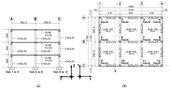
Figure 3.
Case-study building: (a) front view (y-z plane); (b) plan view. Dimensions in [cm].
4.2. Step 1—Structural and Energy Assessment of the AS-IS Building
4.2.1. Building Model
The three-dimensional finite element (FEM) model of the case-study structure was developed using the commercial software SAP2000 V. 26 [37]. Materials and modeling details for structural elements are reported in [31]. As updated modeling assumptions made before the previous study, all beams and column joints are modeled with an end-length offset assigning a rigidity zone factor of 0.5 in order to take into account the rigidity of the beam–column joints. This latter modeling assumption makes the adopted model different from that reported in ref. [31], where beam–column joints were modeled as infinitely rigid elements. For gravitational loads, permanent and variable load values of 5.19 kN/m2 and 2.0 kN/m2, respectively, were assigned to each floor, while values of 5.39 kN/m2 and 0.5 kN/m2 were considered at the roof level. Based on the location characteristics, a snow load of 1.3 kN/m2 was also applied to the roof. The infill walls were modeled as equivalent line loads acting on the perimeter beams of 4.9 kN/m, whereas their contribution to structural stiffness was neglected. To account for seismic effects, the masses associated with the gravitational loads were combined following the provisions of the Italian seismic code [26].
Given the plan symmetry of the building, two-dimensional analyses were performed considering the direction corresponding to the weakest structural response (y-axis). Dynamic time-history analysis with direct integration was performed, assuming a time step of 0.005 s, and employing the Hilber–Hughes–Tayor alpha integration method. All analyses were linear-elastic; no material/geometric nonlinearities were included. Proportional damping was assumed, assigning a damping ratio of 5% for all the vibration modes.
Concerning energy analysis, hourly dynamic simulations based on the TRNSYS18 environment [38], a software package that simulates the behavior of transient systems, were carried out. Only the building was simulated using the TRNBUILD module. This means that only the building thermal needs were calculated through TRNSYS18, while the primary energy consumption was obtained via direct calculation in a spreadsheet. Space heating and cooling loads are affected by the building envelope design, while domestic hot water (DHW) production, lighting and ventilation do not depend on the envelope thermal properties. So, DWH, lighting and ventilation can be assumed to be “invariant” with respect to the kind of analysis that is proposed in this paper, and for the sake of brevity they have been excluded from the analysis since they do not add to the discussion. Within TRNSYS18, the Type56 component was utilized to model the building’s thermal behavior, dividing it into separate zones. In this work, three separate thermal zones were set up to represent the different areas of the building (one for each floor), as well as one for the vertical extension, corresponding to the three apartments on the ground, first and second floors and the new third floor. Type56 was used in the so-called “energy rate mode”, where a predefined internal temperature “setpoint” schedule is provided and the necessary heating or cooling load is determined as the output. The boundary conditions for the thermal simulations were the outdoor temperature, global solar radiation on the horizontal, relative humidity and wind speed, determined on an hourly basis according to the Italian Test Reference Year for the specific town [32]. Ground temperature was set at 12.5 °C. Since this approach is widely adopted for calculating building-specific energy consumption based on various international standards, it was assumed for the all the analyses.
Each thermal zone was modeled by defining opaque and glazed surfaces, occupant schedules, heating/cooling setpoints, and infiltration rates. In Type56, the orientation of all building surfaces and the desired outputs were specified. For this study, the hourly sensible heating and cooling energy demands were selected as key outputs. The model was then connected in TRNSYS18 Simulation Studio to the weather data reader, psychrometric processor, sky temperature and solar radiation models, and online plotters for result visualization. After assembling the system, simulations were performed by loading the climatic data and generating output plots. No specific HVAC plant was modeled, since the proposed retrofit measures focused solely on the building envelope. Consequently, the existing heating and cooling systems were assumed to be unchanged, as detailed in Section 3.2.
The adopted time step for computing the building’s transfer functions was set to 1 h, consistent with the temporal resolution of the overall simulation. Although it would have been possible to adopt a shorter timestep (down to 0.25 h), given that the transfer function timestep must not exceed that of the full simulation, a 1 h timestep was preferred. This choice was justified by the availability of hourly Italian national weather data [32] and the standard recommendation to avoid interpolating solar radiation data [38]. The energy balance excluded domestic hot water and lighting systems, as they are independent of climate and unaffected by the proposed measures. Mechanical ventilation was also not considered. The HVAC operation was defined as follows: heating at 21 °C from 6:00 to 22:00, with night setback to 16 °C, and cooling at a setpoint of 26 °C.
4.2.2. Action Models: Earthquakes and Climate
For the dynamic time-history analyses, seven real earthquake records were chosen from [39], adopting the Rexel software [40]. The selection was guided by the target spectrum from the Italian code [26] for the L’Aquila area, referring to the Life Safety limit state with a 10% chance of exceedance in 50 years (return period of 475 years), with details reported in ref. [31].
The accelerograms were scaled across the whole period range to match the spectral ordinate at the first period of the existing structure. Figure 4 shows the adopted set of accelerograms with compatible response spectra. The climatic parameters adopted are listed in Table 4. Hourly climatic data for simulations were obtained from the Italian Thermo-Technical Committee website [41].
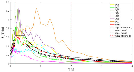
Figure 4.
Adopted set of accelerograms with compatible response spectra (site: L’Aquila).
Table 4.
Geographical and climate characteristics of the area.
4.2.3. Assessment
Structural Assessment
The dynamic behavior of the existing building was initially characterized through modal analysis, which identified the fundamental vibration properties of the structure, natural frequencies, mode shapes and associated participating masses.
As intrinsic dynamic parameters, they are independent of the seismic excitation. The first three modes of vibration obtained from the 3D model of the existing building, in the following indicated as AS-IS, in plane analysis are depicted in Figure 5, while the corresponding vibration periods and participating mass ratios are reported in Table 5. The eigenvector corresponding to the first mode, ϕLS = [0.34 0.76 1]T, is adopted as a shape function to obtain the 2-DOF model characteristics. It can be observed that the first three modes excite almost the entire mass of the building; as a result, they are sufficient to describe the overall structural dynamic behavior. The three modes are well separated, with the first mode exciting 87% of the mass in translational motion along the y-axis. The high percentage of mass participation in the first mode suggests that a reduced single-degree-of-freedom (SDOF) model is adequate to represent the dynamic behavior of the AS-IS building for the design of the retrofit intervention. Based on the results of the modal analysis, given that the total mass of the building is 447.34 kNs2/m, the AS-IS building reduced-order model parameters are = 241.192 kNs2/m, = 8.38 rad/s and . Such parameters, evaluated as described in Table 1, are utilized for the design of the vertical extension with the IIS.
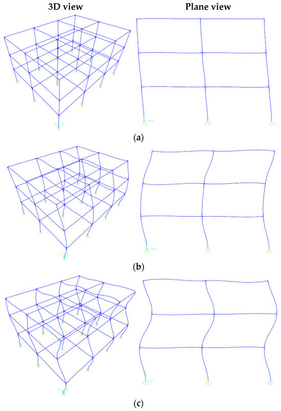
Figure 5.
FEM model of the AS-IS building modal analysis (left side: 3D view; right side: plane view): (a) first mode; (b) second mode; (c) third mode.
Table 5.
First three modal periods and associated participating mass ratios: AS-IS model and the two retrofit configurations, II-S1 (rigid vertical extension) and II-S2 (flexible vertical extension).
The seismic safety assessment was carried out by analyzing the structural responses derived from a set of seven ground motion records, processed through time-history analysis in accordance with the relevant code provisions [26]. The main response parameters considered for the evaluation included relative displacements, inter-story drifts, absolute accelerations and shear forces. The outcomes for the AS-IS building are presented and discussed as reference case in Section 4.5.2. The AS-IS building responses serve as the baseline for assessing the efficiency of the retrofit strategy discussed in the following sections.
Energy Assessment
The envelope, typical of Italian buildings constructed before the 1980s, is characterized by low thermal resistance. Based on data from the Italian EPBD standard [42], materials and layers were modeled in TRNSYS18 with calculated thermal properties. The external hollow-brick walls have a U-value of 1.45 W/(m2K); the roof and basement floor (mixed brick-RC) have U-values of 1.09 W/(m2K) and 0.98 W/(m2K), respectively, assuming a ground conductivity of 2.00 W/(mK) and temperature of 12.5 °C. The building is equipped with double-glazed windows framed in wood (U = 2.83 W/(m2K), SHGC = 0.755), and the infiltration rate is set to 0.3 vol/h as per European standards [43].
No modifications were made to the heating and cooling system or to the thermal energy conversion unit throughout the simulation of both the existing condition and the retrofit scenarios. As a result, the characteristics of the heating and cooling systems were defined based on standard values provided by Italian regulations [27]. Specifically, a natural gas boiler and an air-to-air heat pump were adopted for heating and cooling, as detailed in Table 5.
The equation defining the total energy balance of the building site, with reference to Primary Energy Consumption (PEC), is expressed as
where and are the Primary Energy Consumption (kWhp) values for gas and electricity, respectively; and indicate the net heating and cooling demands (kWh); and stands for the primary electricity conversion factor, assumed for Italy = 2.42 [27].
In the study, the coefficients and were assumed to be equal to 0.92 and 2.5, respectively, according to the assumptions made in ref. [31].
Table 6 summarizes the computation of the annual per square meter, based on the defined energy parameters in Equation (10).
Table 6.
Results of energy simulations on the AS-IS building.
4.3. Step 2—Definition of the Integrated Retrofit Strategy
The conceptual layout of the retrofit intervention is illustrated in Figure 2a. The proposed strategy involves the addition of a one-story vertical extension, with the total height of the new level matching the inter-story height of the existing structure. The materials, structural systems and thermal insulation solutions adopted for the intervention are designed in compliance with current construction standards and energy efficiency regulations.
Regarding the structural component of the integrated retrofit, two alternative design configurations have been developed. The first design fully adheres to the assumptions outlined in Section 3.1, based on the fundamental hypothesis that the vertical extension behaves as a rigid body above the IIS. In contrast, the second design relaxes these assumptions, envisaging a lighter and more flexible vertical extension compared to the first solution. The adoption of two distinct structural designs serves a dual purpose: firstly, to verify whether the rigid-body assumption remains valid even when the extension and the IIS do not strictly satisfy the two remarks prescribed by conventional base isolation theory; secondly, to assess whether a vertical extension designed with reduced stiffness and mass, yet following the same design approach based on the simplified 2-DOF model discussed in Section 3.1, can still deliver effective seismic performance and control.
4.4. Step 3—Design of the Integrated Intervention
The intervention is designed according to indications reported in Section 3. For the structural part, two designs variants are considered, in the following indicated as II-S1 and II-S2, for the rigid vertical extension and the flexible vertical extension design, respectively. Concerning the energy part of the integrated intervention, a unique design is conducted, valid for both cases, as described in detail in the following subsections.
4.4.1. Seismic Retrofit Design
The vertical extension is designed to be constructed entirely with steel framing, allowing for the potential future disassembly of structural elements and their reuse in new constructions, in line with the principles of the circular economy. The structural design follows the Italian code prescriptions [26].
As gravitational loads, based on the energy design of the various horizontal components of the vertical extension, permanent and variable loads of 2.2 kN/m2 and 2.0 kN/m2, respectively, were assigned to the walkable floors (the ultimate layer of the intermediate slab, with the stratigraphy detailed in Figure 6a), while loads of 1.61 kN/m2 and 0.5 kN/m2 were assigned to the new roof (with the stratigraphy detailed in Figure 6b). The snow load assumed for the new roof was 1.3 kN/m2. A layered assembly engineered to achieve high thermal efficiency was adopted for the perimeter walls, as depicted in Figure 6c: double external gypsum-fiber board, 10 cm high-density rock wool, one acoustic plasterboard panel, 10 cm high-density rock wool and a double internal plasterboard panel, with a total thickness of 26.5 cm and a distributed load of 0.85 kN/m2.
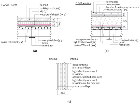
Figure 6.
Vertical extension slab stratigraphy: (a) at the walkable floor and (b) at the roof floor; (c) perimetral wall stratigraphy. Dimensions in [cm].
Vertical bracings were incorporated along selected portions of all four sides of the structure in order to support lateral loads. The floor slab at the walkable level and the roof slab were stiffened by means of horizontal bracing elements placed between the secondary beams across the entire surface in order to ensure rigid diaphragm behavior, spreading and transferring the horizontal actions to the vertical elements. For the purpose of assessing the effects produced by seismic excitation, the masses derived to gravitational loads are assembled according to the code provisions [26]. A schematic representation of the building with the vertical extension and the IIS along with the dimensions of the structural members is provided in Figure 7a,b for the exemplificative case of flexible vertical extension II-S2.
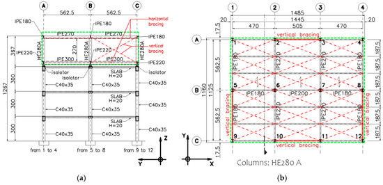
Figure 7.
Vertical extension and IIS, design II-S2: (a) front view (y-z plane); (b) plan view. Red lines represent horizontal and vertical bracings; green lines represent the vertical extension volume/area. Dimensions in [cm].
In the numerical model, rigid links were implemented to model the bracings with an axial stiffness equivalent to that of the bracing elements; a view of the 3D model of the stand-alone vertical extension is presented in Figure 8a.
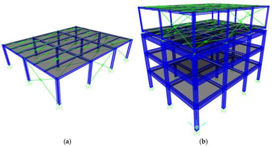
Figure 8.
Three-dimensional FEM models of (a) the stand-alone designed vertical extension and (b) the AS-IS building with the vertical extension and IIS.
Compared to solution II-S2, depicted in Figure 8b, the design solution II-S1 differs in the increased dimensions of the columns of the vertical extension and the increased mass of the roof slab in order to equalize the base mass of the slab at the walkable level. These differences result in a stiffer and heavier vertical extension compared to solution II-S2.
According to the two designs, the dynamic characteristics, in terms of the mass, natural frequency and period of the vertical extension were estimated. Based on the mass evaluated for the two design variants, the mass ratio, (Table 7), is given according to Equation (8), and, applying the design by maximization of the EDI objective function, the IIS optimal parameters and are obtained. Finally, from these values, the global stiffness and damping coefficient of the IIS are evaluated with Equation (9). The design parameters of the two structural variants are reported in Table 7 according to the definition of the parameters reported in Equations (8) and (9). The mass of the vertical extension; the sum of the upper structure and the base mass; the natural frequency of the upper structure, ; and the natural frequency of the isolated system, , evaluated as defined in Equation (4), as well as their natural periods, and , respectively, are reported in Table 8.
Table 7.
Seismic parameters used in the design of the two retrofit configurations.
Table 8.
Dynamic properties of the two structural designs for the vertical extension.
Based on the two designed structural configurations, it is possible to observe in Table 9 that the assumptions outlined in Section 3.1 regarding the applicability of the 2-DOF model in designing the IIS connecting the existing structure and the vertical extension are fully satisfied in design solution II-S1, since they meet both Remarks 1 and 2 reported in Equations (5) and (6), whereas they are not satisfied in design solution II-S2.
Table 9.
Verification of the rigid-body assumption for the vertical extension: vertical extension base mass, ; superstructure mass, ; and ε value, evaluated for the two structural designs considered for the vertical extension.
4.4.2. Energy Retrofit Design
The construction design of the extension’s building envelope walls and floors/roof took into account the need for a lightweight structure, the thermal needs in compliance with the Italian building code and the acoustic insulation.
Therefore, the construction of the walkable floor provides a consistent thermal insulation and OSB board for soundproofing, with the dimensions reported in Figure 6a. The new roof is equipped with a generous layer of rock wool thermal insulation with dimensions reported in Figure 6b. The outer walls are provided with double thermal layers of insulation (rock wool) and three detached layers of plasterboard (inner and outer with double board, midway single board) for improved soundproofing (Figure 6c).
From the thermo-energetic point of view, the vertical extension consisted of (1) the creation of a new space above the existing one, with thermal properties determined according to present Italian law prescriptions, and (2) the insulation of the roof separating the AS-IS second floor and the new space.
The features of the space heating and cooling systems in terms of the efficiency of the AS-IS building remain the same in the vertical extension space. The main thermal features of the designed new vertical extension, according to the national standards, are summarized in Table 10.
Table 10.
Thermal transmittance of the various building components for the AS-IS case and the building with the interventions II-S1 and II-S2.
The architectural elevations of the building, including the proposed vertical extension, were generated using Revit software [44] and are illustrated in Figure 9. It can be observed from the four façades that the existing structure and the new upper floor have comparable wall surface areas; however, the shape and distribution of the windows differ. This variation primarily results from the construction technique adopted for the external walls of the extension, which imposes specific constraints on the positioning of glazed openings. Despite these differences in shape and arrangement, the total glazed surface per façade orientation remains consistent between the existing building and the vertical extension. In particular, the window areas are 6.4 m2 on both the north and south façades per floor and 4.8 m2 on both the east and west façades per floor. The model built with Revit software is able to furnish a tridimensional representation of the building with the vertical extension and facilitates the integration of thermal properties for all building surfaces. The model can integrate tools to perform life cycle assessment analysis allowing for the evaluation of environmental impacts associated with the integrated intervention proposed [45].
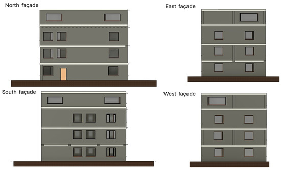
Figure 9.
Prospects of the existing building with the vertical extension.
4.5. Step 4—Assessment of the Structure with the Integrated Intervention
4.5.1. Retrofitted Building Model
The retrofitted building FEM models were constructed on the basis of the existing structure model detailed in Section 4.2.1 and the vertical extension design model discussed in Section 4.4.1. The IIS was implemented using 12 isolators installed at the interface above the existing structure, arranged in correspondence with each column and modeled using linear link elements. The lower node of each link element was connected to the corresponding node at the top floor of the existing building, while the upper node was connected to the corresponding node of the walkable slab of the vertical extension. The horizontal stiffness and damping properties of each isolator were set to 1/12 of the total stiffness, , and total damping, , respectively, as reported in Table 7. The axial stiffness was assumed to be 800 times the horizontal stiffness, and the axial damping was taken as zero, in accordance with the recommendations in [26]. A view of the 3D model of the AS-IS building with the vertical extension and IIS is shown in Figure 8b.
4.5.2. Structural and Energy Assessment
Structural Assessment
The results of the dynamic analysis performed on the retrofitted models with the integrated interventions II-S1 and II-S2 are presented in Table 5. These results were used to evaluate whether the rigid-body assumption for the vertical extension remains valid, even though it does not fully comply with the conventional criteria established by base isolation theory. It is evident that the implementation of the IIS markedly modifies the dynamic response of the AS-IS building. The fundamental period increases to 1.30 s and 1.29 s for interventions II-S1 and II-S2, respectively, while the second and third modes exhibit periods of 0.66 s and 0.21 s. These three modes involve the entire mass of the building and are sufficient to characterize its global dynamic response. As a representative example, the first three vibration modes obtained from the 3D retrofitted model with the integrated intervention II-S1, representing the stiffest and heaviest solution, are illustrated in Figure 10. The vertical extension clearly behaves as a rigid body, effectively acting as a tuned mass system decoupled from the lower structure through the IIS.
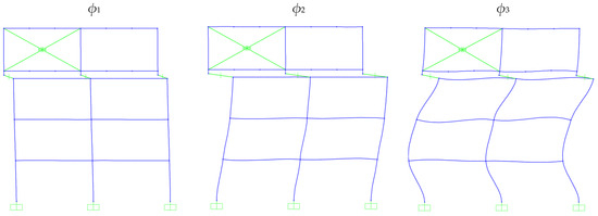
Figure 10.
First three modes (ϕ1, ϕ2 and ϕ3) of vibration with integrated intervention II-S1.
To facilitate comparison of the two retrofitted configurations, the mode shapes corresponding to interventions II-S1 and II-S2 (the latter representing the more flexible and lighter configuration) are reported in Figure 11. For clarity, the modal displacements are plotted in planar graphs, with each mode vector normalized to unity at the top floor of the AS-IS building (Floor 3). The overlapping of the three modal vectors confirms that both integrated solutions yield nearly identical modal behavior.
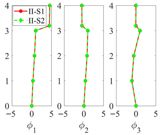
Figure 11.
First three modes of vibration with integrated interventions II-S1 and II-S2.
Thus, even the more flexible configuration, which does not strictly satisfy the two theoretical conditions discussed in Section 3.1, exhibits rigid-body behavior with respect to the lower structure. Consequently, the simplified 2-DOF model is suitable for the design of both integrated retrofit solutions, II-S1 and II-S2. In conclusion, despite minor differences in mass and stiffness, both interventions produce a very similar dynamic response in the retrofitted structure.
The seismic performance of the retrofitted structure incorporating the two proposed integrated interventions was evaluated through time-history analyses using a set of seven ground motion records. The structural responses are summarized in Figure 12a–d for both interventions II-S1 and II-S2, alongside the results obtained for the AS-IS configuration for comparison purposes. The figures show, as a function of building height, the mean peak values of the relevant response quantities considered across the seven seismic inputs. The results clearly demonstrate that the vertical extension designed with either intervention II-S1 or II-S2 significantly reduces the seismic response of the original AS-IS building. from the seven earthquake records.
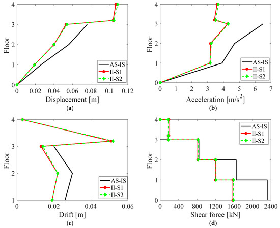
Figure 12.
Mean peak response values obtained from the set of seven accelerograms: (a) relative displacement; (b) absolute acceleration; (c) inter-story drift; (d) shear force. Legend: AS-IS case; retrofitted configurations II-S1 and II-S2.
As anticipated from modal analysis, all maximum response values are comparable between the two retrofit solutions. Specifically, the reductions achieved with respect to the AS-IS case are as follows: top-floor displacement reduced by 30% (II-S1) and 29% (II-S2); top-floor absolute acceleration reduced by 35% (II-S1) and 34% (II-S2); maximum inter-story drift reduced by 35% (II-S1) and 30% (II-S2); base shear force reduced by 32% (II-S1) and 31% (II-S2). These results confirm the effectiveness of both retrofit strategies in mitigating seismic demand while maintaining comparable performance levels.
A crucial consideration is the assessment of the existing structure’s adequacy with respect to the support of additional gravitational loads induced by the vertical extension. In this regard, Figure 13 shows the verification of the axial forces in the base columns of the building under a seismic load combination with a set of seven earthquakes adopted, in accordance with the provisions of [26]. In the abscissa of the graph, the number of the column considered, according to the position of the elements in the plan, as reported in Figure 3b, is reported. In the ordinate there is the ratio between the design axial force, , and the 65% of the axial load-bearing capacity, , of each element. Continuous lines represent the results obtained for the AS-IS building for the seven earthquakes, while the colored circles report the same value obtained for the integrated intervention (Figure 13a in the case of II-S1 and Figure 13b for II-S2). The results confirm that all base columns satisfy the requirements for all earthquakes considered, even after the implementation of the vertical extension using the two design solutions, II-S1 and II-S2. Consequently, the proposed retrofit intervention does not require any local strengthening of the vertical load-bearing elements.
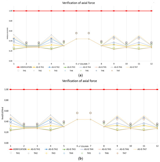
Figure 13.
Verification of maximum axial force at the base columns for the AS-IS building and the retrofitted one with the two interventions for designs (a) II-S1 and (b) II-S2.
Energy Assessment
Energy simulations were carried out to evaluate the specific PEC of the building for heating and cooling, with the aim of assessing the impact of the proposed vertical extension on the energy performance of the existing structure.
In line with the integrated retrofit strategy adopted in this study, the analysis focused on how the addition of a well-insulated upper floor affects the thermal performance of the AS-IS portion of the building. To this end, the results reported in Table 11 refer exclusively to the existing part of the building, before and after the implementation of the vertical extension with the IIS. As shown in Table 10, the retrofit scenario (solutions II-S1 and II-S2) leads to a notable reduction in heating demand, , and cooling demand, , in the existing structure. This improvement is mainly attributed to the transformation of the previous roof into an insulated intermediate slab, which reduces heat loss during winter. Additionally, the presence of the extension above the existing volume also acts as a thermal buffer, mitigating solar heat gains in summer and consequently lowering cooling demand on the uppermost existing floor.
Table 11.
Results of energy simulations for the AS-IS building and the building with the interventions.
To complete the analysis, Table 12 reports two additional scenarios not used in the final selection of the optimal retrofit solution but which are still informative for understanding the global performance of the system.
Table 12.
Energetic output for the sole extension and the overall building.
The first line presents the energy performance of the vertical extension alone (VEA), while the second line refers to the overall building (OB), including both the existing part and the new extension.
These results highlight two key points: (1) The superior thermal performance of the extension: the vertical extension, designed with high insulation levels and compliant with current energy standards, exhibits significantly lower heating demand compared to the existing building. However, its cooling demand is relatively higher, likely due to increased solar exposure and reduced thermal mass. (2) A global improvement in energy efficiency: when considered as part of the overall building, the extension contributes to a meaningful reduction in the total PEC of the structure. The integration of the high-performance volume not only offsets part of the existing building’s inefficiency but also improves the average specific consumption of the entire complex.
This confirms that, beyond offering additional usable space and structural benefits through the IIS, the vertical extension also plays a significant role in enhancing the global energy performance of the building, thereby validating the integrated nature of the proposed retrofit approach.
4.6. Step 5—Optimal Choice of the Integrated Intervention
To obtain a unified evaluation of structural and energy outcomes, two dimensionless indices are introduced, one reflecting seismic response and one representing energy demand, defined so that values below unity denote improvement with respect to the reference building. A count indicator, h, is utilized, where h = 1 corresponds to intervention II-S1, while h = 2 corresponds to II-S2.
Regarding the structural performance indicator, it is derived from the inter-story drifts of the primary structure, which represent key measures of seismic vulnerability. Defining as the drift vector for the h-th intervention, where each component, (for floors i = 1–3), corresponds to the peak drift at floor i under n ground motion, the drift index, , is defined as
This index represents the average drift response across the height of the structure, normalized with respect to the AS-IS configuration over the suite of ground motion records.
As an energy performance indicator, PEC is considered. Corresponding to the h-th intervention, the energy index, , is indicated as
where denotes the of the retrofitted model, referenced to the AS-IS value.
By assigning equal weight to the structural and energy components of the interventions, a bi-objective index, denoted as , is defined as the arithmetic mean of the structural index, , and the energy index, .
It is worth highlighting that the same performance indices, and were also adopted by the authors of [31] to evaluate the effectiveness of other integrated strategies employing different passive control systems. This consistency allows for a direct and meaningful comparison of the performances of the present vertical extension with the IIS and previous results reported in the literature. Such a comparison is further justified since the same case-study building and action models were employed in both studies. For this purpose, the integrated interventions II-S1 and II-S2 proposed in this work are compared with two retrofit configurations taken from [31], both based on the TMD concept and applied at the roof level of the same building:
- II1, a non-conventional TMD with a cool roof system;
- II3, a large-mass TMD with a green roof.
The results of the seismic and energy analyses, discussed in Section 4.5.2, are summarized in Table 13 in terms of the adopted performance indices.
Table 13.
Performance indicators evaluated for the integrated interventions.
Focusing first on the two interventions proposed herein, II-S1 and II-S2, the slightly superior structural performance of II-S1 emerges through observation of the structural index, , while, by definition, both interventions achieve the same energy index, . Consequently, the bi-objective index, , captures the marginally higher overall performance of II-S1, identifying it as the optimal solution among the two variants. When compared with the interventions II1 and II3 in the literature, the proposed vertical extensions with the IIS configurations demonstrate superior performance in both structural and energy domains.
Structurally, the improved effectiveness can be attributed to the larger equivalent mass of the vertical extension (103.05 kNs2/m for II-S1 and 99.19 kNs2/m for II-S2) compared to the roof-mounted TMD systems (92 kNs2/m and 80 kNs2/m for II1 and II3, respectively; ref. [31]). This finding aligns with the well-established principle that TMD systems with greater mass ratios achieve enhanced vibration mitigation. Energetically, the vertical extension provides additional thermal insulation and mass, improving the building’s overall energy efficiency beyond what can be achieved by passive roof-level interventions alone. The creation of an upper insulated volume reduces both winter heat loss and summer heat gain, enhancing envelope performance across seasons.
In summary, the adoption of combined performance indices proved effective in capturing the dual nature of the retrofit objective, integrating seismic safety and energy efficiency within a unified metric.
The results confirm that vertical extension with the IIS can be optimized to achieve meaningful improvements in both domains, reinforcing its role as a viable and sustainable retrofit strategy in line with the goals of this study.
5. Conclusions
The paper explored how coupling vertical extension with the IIS can act as a dual-purpose measure to enhance both seismic and thermal performance in existing buildings. Grounded in sustainable and circular design principles, the strategy offers an efficient approach to upgrade existing buildings through vertical densification while limiting land use. Far from being a mere addition of space, it has been demonstrated that vertical extension becomes an active component of the rehabilitation strategy, contributing to the structural dynamics of a system as a tuned mass and improving thermal performance through compliance with current energy standards.
The study developed and applied a five-step methodology for the design and implementation of the proposed integrated retrofit strategy, tested on a reinforced concrete building located in L’Aquila, Italy.
The main results obtained are summarized in the following.
From the structural perspective:
- Two design variants (II-S1 and II-S2) were analyzed through modal and nonlinear time-history analyses;
- Both configurations confirmed that the vertical extension behaves as a rigid body effectively decoupled from the existing structure via the IIS;
- The simplified 2-DOF model proved to be accurate and efficient, capturing the essential dynamic behavior;
- Compared to the AS-IS building, reductions of up to 35% in top-floor acceleration, 30–35% in inter-story drift, and over 30% in base shear were achieved, without requiring local strengthening of vertical elements.
From the energy perspective:
- The vertical extension led to an approximately 11% reduction in the specific primary energy demand of the existing portion;
- The new high-performance envelope, intermediate insulated slab and added thermal mass contributed to reduced winter heat losses and lower summer heat gains, improving comfort and protecting the existing envelope.
A bi-objective performance index, equally weighting structural and energy improvements, identified variant II-S1 as slightly more effective, though both variants performed comparably well.
In conclusion, the vertical extension with the IIS emerged as a robust, scalable and integrative retrofit solution capable of addressing the seismic vulnerability and energy inefficiency of existing buildings within a unified design framework.
Future developments may include the extension of the proposed methodology to multi-story vertical additions and different structural typologies, assessing the limits of the rigid-body assumption and the effectiveness of simplified models. Further research could also integrate active energy systems and life cycle assessment to evaluate environmental impacts.
Future developments will focus on verifying compliance with current code requirements and enhancing the structural model to capture nonlinear behavior, providing a more comprehensive performance assessment of the proposed strategy.
The authors would like to add that, given the exploratory nature of the study, some practical engineering implementation aspects were not explicitly addressed, such as
- The continuity and adaptation of vertical service lines between the existing building and the new extension;
- The practical realization of a rigid diaphragm layer at the isolation interface level;
- Potential torsional effects induced by plan or stiffness irregularities between the existing building and the new extension.
Addressing these aspects through future research is essential to ensure the feasibility and robustness of inter-story isolation in practice.
Author Contributions
Conceptualization, M.B.; methodology, M.B. and F.B.; software, M.B., F.B. and R.P.; validation, M.B., F.B. and R.P.; formal analysis, M.B. and F.B.; investigation, M.B., F.B. and R.P.; resources, M.B., F.B. and R.P.; data curation, M.B.; writing—original draft preparation, M.B. and F.B.; writing—review and editing M.B.; visualization, M.B.; supervision, M.B. and F.B.; project administration, M.B.; funding acquisition, M.B. All authors have read and agreed to the published version of the manuscript.
Funding
This research was funded by UNIVERSITAS MERCATORUM of Rome, Italy, grant number 24-FIN/RIC (financial framework 2024).
Data Availability Statement
Data will be made available on request.
Acknowledgments
The authors gratefully acknowledge Umberto Tirabassi for his valuable contribution to this research through his support with numerical analyses.
Conflicts of Interest
The authors declare no conflicts of interest.
References
- Julistiono, E.K.; Oldfield, P.; Cardellicchio, L. Up on the roof: A review of design, construction, and technology trends in vertical extensions. Archit. Sci. Rev. 2023, 67, 63–77. [Google Scholar] [CrossRef]
- Argenziano, M.; Faiella, D.; Bruni, F.; De Angelis, C.; Fraldi, M.; Mele, E. Upwards—Vertical extensions of masonry built heritage for sustainable and antifragile urban densification. J. Build. Eng. 2021, 44, 102885. [Google Scholar] [CrossRef]
- Feng, M.Q.; Mita, A. Vibration control of tall buildings using mega subconfiguration. J. Eng. Mech. 1995, 121, 1082–1088. [Google Scholar] [CrossRef]
- Esposito, F.; Faiella, D.; Mele, E. Intermediate isolation system with nonlinear lower structure and isolation system. Appl. Sci. 2023, 13, 4590. [Google Scholar] [CrossRef]
- Jeong, S.; Kim, D. Estimation of design axial stiffness of reinforcing piles in vertical extension remodelling process using numerical computation. Eng. Struct. 2020, 214, 110623. [Google Scholar] [CrossRef]
- Dind, A.; Lufkin, S.; Rey, E. A modular timber construction system for the sustainable vertical extension of office buildings. Designs 2018, 2, 30. [Google Scholar] [CrossRef]
- Lešnik Nedelko, M.; Kravanja, S.; Premrov, M.; Žegarac Leskovar, V. Development of methodology for estimation of energy-efficient building renovation using application of MINLP-optimized timber–glass upgrade modules. Sustainability 2025, 17, 319. [Google Scholar] [CrossRef]
- Ziyaeifar, M.; Noguchi, T. Partial mass isolation in tall buildings. Earthq. Eng. Struct. Dyn. 1998, 27, 49–65. [Google Scholar] [CrossRef]
- Faiella, D.; Mele, E. Vibration characteristics and higher mode coupling in intermediate isolation systems (IIS): A parametric analysis. Bull. Earthq. Eng. 2019, 17, 4347–4387. [Google Scholar] [CrossRef]
- Reggio, A.; De Angelis, M. Optimal energy-based seismic design of non-conventional tuned mass damper (TMD) implemented via inter-story isolation. Earthq. Eng. Struct. Dyn. 2015, 44, 1623–1642. [Google Scholar] [CrossRef]
- Bernardi, E.; Donà, M.; Tan, P. Multi-objective optimization of the inter-story isolation system used as a structural TMD. Bull. Earthq. Eng. 2023, 21, 3041–3060. [Google Scholar] [CrossRef]
- Esposito, F.; Faiella, D.; Mele, E. A diagram-based design procedure for intermediate isolation system in existing buildings with inelastic behavior. Earthq. Eng. Struct. Dyn. 2024, 53, 1492–1508. [Google Scholar] [CrossRef]
- Di Egidio, A.; Pagliaro, S.; Contento, A. Seismic performance of frame structure with hysteretic intermediate discontinuity. Appl. Sci. 2023, 13, 5373. [Google Scholar] [CrossRef]
- Artés, J.; Wadel, G.; Martí, N. Vertical extension and improving of existing buildings. Open Constr. Build. Technol. J. 2017, 11, 83–94. [Google Scholar] [CrossRef]
- Dinić Branković, M.; Igić, M.; Đekić, J.; Mitković, M. Impact of post-socialist vertical extensions of buildings on outdoor microclimate in collective housing areas: A study of Niš, Serbia. Energy Build. 2022, 265, 112081. [Google Scholar] [CrossRef]
- Lešnik, M.; Premrov, M.; Žegarac Leskovar, V. Optimal design of timber-glass upgrade modules for vertical building extension from the viewpoints of energy efficiency and visual comfort. Appl. Energy 2020, 270, 115173. [Google Scholar] [CrossRef]
- Sebastiani, I.; D’Amore, S.; Pinotti, R.; Pampanin, S. Integrated rehabilitation of reinforced concrete buildings: Combining seismic retrofit by means of low-damage exoskeleton and energy refurbishment using multi-functional prefabricated facade. J. Build. Eng. 2024, 95, 110368. [Google Scholar] [CrossRef]
- Berti, K.; Bienvenido-Huertas, D.; Rubio-Bellido, C.; Romero-Recuero, I. Changing climate in Italian cities and Italian building regulations: Analysis focused on future climate change scenarios. Urban Clim. 2025, 61, 102408. [Google Scholar] [CrossRef]
- Kallioras, S.; Bournas, D.; Koutas, L.; Molina, F.J. Integrated seismic and energy retrofitting of masonry-infilled RC buildings with textile-reinforced mortar and thermal insulation: Full-scale tests on a five-story prototype. J. Build. Eng. 2024, 98, 111006. [Google Scholar] [CrossRef]
- Kallioras, S.; Bournas, D.; Smiroldo, F.; Giongo, I.; Piazza, M.; Molina, F.J. Cross-laminated timber for seismic retrofitting of RC buildings: Substructured pseudodynamic tests on a full-scale prototype. Earthq. Eng. Struct. Dyn. 2024, 53, 4354–4378. [Google Scholar] [CrossRef]
- Ademovic, N.; Formisano, A.; Penazzato, L.; Oliveira, D.V. Seismic and energy integrated retrofit of buildings: A critical review. Front. Built Environ. 2022, 8, 963337. [Google Scholar] [CrossRef]
- Xu, G.; Guo, T.; Li, A.; Zhang, H.; Wang, K.; Xu, J.; Dang, L. Seismic resilience enhancement for building structures: A comprehensive review and outlook. Structures 2023, 59, 105738. [Google Scholar] [CrossRef]
- Yang, F.; Sedaghati, R.; Esmailzadeh, E. Vibration suppression of structures using tuned mass damper technology: A state-of-the-art review. J. Vib. Control 2022, 28, 812–836. [Google Scholar] [CrossRef]
- Faiella, D.; Argenziano, M.; Mele, E. Improving the seismic response of tall buildings: From diagrid to megastructures and mega-subcontrol systems. Open Constr. Build. Technol. J. 2022, 16. [Google Scholar] [CrossRef]
- United Nations. Goal 11: Make Cities Inclusive, Safe, Resilient and Sustainable. Available online: https://sdgs.un.org/goals/goal11 (accessed on 5 October 2025).
- Ministero delle Infrastrutture e dei Trasporti. Norme Tecniche per le Costruzioni 2018; Ministero delle Infrastrutture e dei Trasporti: Rome, Italy, 2018.
- Ministero dello Sviluppo Economico. Decreto Interministeriale 26 Giugno 2015—Applicazione Delle Metodologie di Calcolo Delle Prestazioni Energetiche e Definizione Delle Prescrizioni e Dei Requisiti Minimi Degli Edifici; Ministero dello Sviluppo Economico: Rome, Italy, 2015.
- Pohoryles, D.; Maduta, C.; Bournas, D.; Kouris, L. Energy Performance of Existing Residential Buildings in Europe: A Novel Approach Combining Energy with Seismic Retrofitting. Energy Build. 2020, 223, 110024. [Google Scholar] [CrossRef]
- Clemett, N.; Gallo, W.W.C.; Gabbianelli, G.; O’Reilly, G.J.; Monteiro, R. Optimal Combined Seismic and Energy Efficiency Retrofitting for Existing Buildings in Italy. J. Struct. Eng. 2022, 149, 04022207. [Google Scholar] [CrossRef]
- D’Agostino, D.; Faiella, D.; Febbraro, E.; Mele, E.; Minichiello, F.; Trimarco, J. Steel exoskeletons for integrated seismic/energy retrofit of existing buildings—General framework and case study. J. Build. Eng. 2024, 83, 108413. [Google Scholar] [CrossRef]
- Basili, M.; Busato, F.; De Angelis, M. Integrated seismic and energetic rehabilitation of existing buildings based on the tuned mass damper concept. Results Eng. 2024, 24, 103552. [Google Scholar] [CrossRef]
- UNI 10349-1:2016; Heating and Cooling of Buildings—Climatic Data—Part 1. UNI: Milan, Italy, 2016.
- UNI 5364:1976; Hot Water Heating Systems: Rules for Presentation of Offer and for Testing. UNI: Milan, Italy, 1976.
- Chopra, A.K. Dynamics of Structures: Theory and Applications to Earthquake Engineering, 6th ed.; Pearson Education: London, UK, 2023. [Google Scholar]
- Kelly, J.M. Earthquake-Resistant Design with Rubber; Springer: London, UK, 1997. [Google Scholar]
- Italian Government. Ministerial Decree of 5 December 1997, Determination of Passive Acoustic Requirements for Buildings. Gazzetta Ufficiale Della Repubblica Italiana, 22 December 1997; No. 297. [Google Scholar]
- Computers & Structures, Inc. SAP2000 Software, version 26; Computers & Structures, Inc.: Walnut Creek, CA, USA, 2025.
- Klein, S.A.; Beckman, W.A.; Mitchell, J.W.; Duffie, J.A.; Duffie, N.A.; Freeman, T.L. TRNSYS 18: A Transient System Simulation Program: Mathematical Reference; Solar Energy Laboratory, University of Wisconsin–Madison: Madison, WI, USA, 2018; Volume 4. [Google Scholar]
- Istituto Nazionale di Geofisica e Vulcanologia. ITACA: Italian Accelerometric Archive. Available online: http://itaca.mi.ingv.it (accessed on 5 October 2025).
- Iervolino, I.; Galasso, C.; Cosenza, E. REXEL: Computer aided record selection for code-based seismic structural analysis. Bull. Earthq. Eng. 2009, 8, 339–362. [Google Scholar] [CrossRef]
- Comitato Termotecnico Italiano. Available online: https://www.cti2000.it/index.php?controller=news&action=show&newsid=34985 (accessed on 5 October 2025).
- UNI/TS 11300-1:2008; Energy Performance of Buildings Part 1: Evaluation of Energy Need for Space Heating and Cooling. UNI: Milan, Italy, 2008.
- UNI EN ISO 13790:2008; Energy Performance of Buildings: Calculation of Energy Use for Space Heating and Cooling. UNI: Milan, Italy, 2008.
- Autodesk Inc. Autodesk Revit, version 2026; Autodesk Inc.: San Rafael, CA, USA, 2025.
- Parente, R.; Tavolare, R. Representation architectural heritage: HBIM and IoT for the safety. Abitare Terra 2023, 21 (Suppl. 60), 52–56. [Google Scholar]


Disclaimer/Publisher’s Note: The statements, opinions and data contained in all publications are solely those of the individual author(s) and contributor(s) and not of MDPI and/or the editor(s). MDPI and/or the editor(s) disclaim responsibility for any injury to people or property resulting from any ideas, methods, instructions or products referred to in the content. |
© 2025 by the authors. Licensee MDPI, Basel, Switzerland. This article is an open access article distributed under the terms and conditions of the Creative Commons Attribution (CC BY) license (https://creativecommons.org/licenses/by/4.0/).