Abstract
Raindrop erosion of wind turbine blades’ leading edge is a critical degradation mechanism limiting wind turbine blade lifetime and aerodynamic efficiency. Protective coatings have been extensively studied to mitigate this damage. This review critically synthesises current knowledge on coating-based protection strategies against erosion, with emphasis on (i) the underlying mechanisms of erosion, (ii) advances in conventional and emerging coating technologies, and (iii) experimental approaches for testing and lifetime prediction. Across reported studies, nanofiller reinforcement (e.g., CNTs, graphene, CeO2, Al2O3) enhances erosion resistance by 60–99%, primarily through improved toughness and stress-wave dissipation. Hybrid and multifunctional systems further combine mechanical durability with self-healing or anti-icing capabilities. Experimental results confirm that erosion rate follows a power-law dependence on impact velocity, with maximum damage occurring between 45° and 60° impact angles. Softer elastomeric coatings demonstrate longer incubation periods and superior viscoelastic recovery compared with rigid sol–gel systems. Persistent gaps include the lack of standardised testing, poor field–lab correlation, and limited long-term durability data. Future work should focus on coordinating multi-stressor testing with variable-frequency rain setups to replicate real field conditions and enable reliable lifetime prediction of next-generation erosion-resistant coatings.
1. Introduction
The global imperative to transition towards sustainable energy sources has positioned wind power as a cornerstone in reducing greenhouse gas emissions and achieving the ambitious COP28 goal of tripling global renewable energy capacity to 320 GW by 2030 [1,2]. In 2024 alone, 117 GW of new wind energy capacity was installed, elevating the global total to 1136 GW. Projections indicate this upward trend will persist, with new installations anticipated to reach 139 GW in 2025 [1]. A key enabler of this expansion is the deployment of larger turbines, driven by the significant benefits of increased rotor diameters. Larger swept areas allow turbines to capture more kinetic energy from the wind, directly leading to higher electricity production while providing more consistent power output and enhancing grid stability [3,4]. Additionally, they enhance operational flexibility, enabling electricity generation at lower wind speeds and across more diverse environmental conditions [3]. As a result of these advantages, the industry has seen development of formidable turbines. The latest prototypes and announced models have reached impressive capacities of up to 26 MW and rotor diameters exceeding 300 m [5]. Concurrently, commercially deployed models, such as Vestas’ 15 MW V236 platform, are becoming increasingly prevalent in major wind farm developments worldwide [6].
However, the increasing scale and rotational speed of these turbines introduce serious operational challenges. One of the most critical of these is the mechanical durability of wind turbine blades, which are directly exposed to environmental forces [7]. Blades are typically constructed from advanced composites. These include glass-fibre-reinforced polymers (GFRPs), which are favoured for their strength-to-weight ratio and design flexibility, and carbon-fibre-reinforced polymers (CFRPs), which are increasingly used in high-performance applications due to their superior stiffness [8,9]. The blade structure often comprises an outer shell or skin, internal shear webs, and a main spar, all designed to withstand immense aerodynamic and structural loads [8]. Crucially, the outermost layer of the blade, especially the leading edge, is directly exposed to the environmental elements throughout its operational life. Protecting this surface is essential for maintaining aerodynamic performance, as even minor erosion or surface roughening can reduce lift, increase drag, and degrade overall energy capture efficiency.
To optimise performance and reduce component costs in these massive turbines, manufacturers often design for higher blade tip speeds. A study by Jamieson [10] suggested that targeting a design tip speed of 120 m/s, compared to a baseline of 75 m/s, could reduce tower top system costs by approximately 15%. While higher tip speeds can lead to reduced drivetrain torque and potentially lower overall system costs [11], they also introduce significant operational challenges. Specifically, the heightened velocities at the blade tips dramatically intensify the impact of raindrops and other airborne particles, leading to accelerated leading edge erosion (LEE) [12,13]. This issue has become a prevalent and costly challenge for industry, evident in numerous high-profile cases across Europe’s offshore wind industry. For instance, significant erosion problems have necessitated widespread repairs at major wind farms such as the Anholt offshore wind farm in Denmark, where Siemens Gamesa initiated a large-scale blade repair and upgrade campaign for 87 of its 111 turbines within five years of operation [14]. Similarly, at the 630 MW London Array in the United Kingdom, which comprises 175 Siemens Gamesa 3.6–120 turbines commissioned in 2013, premature blade erosion was observed, occurring earlier than initially anticipated. This led to plans for an “emergency” repair campaign targeting 140 of its turbines [15]. Additionally, the 108-turbine West of Duddon Sands offshore wind farm also reported widespread erosion problems, requiring extensive repairs [16].
Among the pressing operational challenges facing the wind energy industry is LEE. This pervasive issue affects all types of wind turbines, manifesting as significant degradation of the blade’s aerodynamic profile [12]. LEE is caused by the impact of raindrops, hailstones and other airborne particles, particularly in harsh and coastal environments. These impacts over time lead to the material to being removed from the blade’s leading edge, causing it to become worn and damaged. Offshore wind turbines are particularly vulnerable to LEE. This is primarily due to the more challenging offshore environmental conditions, which include stronger winds that exacerbate erosion.
Given the escalating impact of raindrop erosion on wind turbine performance and economics, a comprehensive understanding of protective coating technologies is essential. This review provides a critical synthesis of the current state of the art in coatings specifically designed to mitigate raindrop erosion on wind turbine blades. The scope encompasses a detailed analysis of raindrop erosion mechanisms, a critical assessment for both existing and emerging coating technologies designed to mitigate this phenomenon, and a thorough exploration of experimental testing methodologies employed for performance evaluation.
2. Mechanisms of Raindrop Erosion
2.1. Physics of Droplet Impact and Stress Wave Propagation
Raindrop erosion on the leading edges of wind turbine blades is a complex, high-energy phenomenon caused by the continuous impact of high-velocity water droplets. This repeated interaction leads to gradual material degradation and surface deterioration driven by a combination of dynamic physical forces and the material’s mechanical response. When a high-velocity raindrop strikes the blade’s surface, it generates a momentary but exceedingly intense pressure pulse, known as water hammer pressure. This sudden pressure can reach magnitudes significantly higher than atmospheric pressure, potentially exceeding the dynamic fracture strength of the protective coating or the underlying composite substrate [17,18]. At the moment of impact, two primary wave fronts are generated: a longitudinal compressional normal stress wave that travels directly through the material, and a transverse shear wave that propagates away from the impact location as illustrated in Figure 1. The shear wave is generated as the contact area between the droplet, and the material increases during impact [12]. Additionally, due to droplet deformation, a Rayleigh wave forms, which remains confined to the target surface.
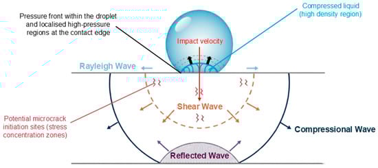
Figure 1.
Schematic illustration of shock wave propagation following raindrop impact on a solid surface. Adapted and redrawn from Refs. [19,20].
A critical aspect of this impact is that the magnitude of the water hammer pressure is critically dependent on the acoustic properties of both the target material and the impacting liquid [12]. Interestingly, the maximum pressure does not occur directly at the epicentre of the impact but rather in a ring around the midpoint, observed at a delayed time. Correspondingly, maximum shear stresses are also observed at these radial locations, albeit for a very short duration [21]. These shock waves do not simply stop at the surface; they propagate through multi-layer systems. Upon contact with the coating, waves travel into both the liquid and the coating, while the remainder is transmitted to the underlying blade structure [21]. The amplitude of this reflected wave is directly dependent on the relative acoustic impedances of the coating and the substrate layers. A significant mismatch in acoustic impedance between layers can lead to a large reflected wave [12,21]. This phenomenon is particularly important because if reflected waves interfere constructively with subsequent impacts or generate high tensile stresses, they can initiate internal damage, most notably delamination at the interface [21,22]. This highlights that the effectiveness of a multi-layer coating system is not solely determined by the individual properties of each layer, but critically by how well their acoustic properties are matched to ensure efficient wave transmission and minimise damaging reflections.
Immediately following the initial water hammer impact, the compressed water droplet spreads rapidly across the surface. This phenomenon, known as lateral jetting or radial outflow, occurs at extremely high speeds, often exceeding the initial impact velocity of the droplet [12,18]. As the water spreads upon impact, it exerts significant shear forces on the material surface, dislodges weakened regions, loosens surface fragments, and contributes to the continued propagation of damage. This high-velocity water flow behaves similarly to a micro-scale cutting tool, further contributing to material wear and the ejection of small particles from the blade surface [18,23]. The manner in which initial impact energy is dissipated by a surface is heavily influenced by its hardness. Harder materials primarily reflect impact energy back into the droplet, which intensifies lateral jetting and splashing. In contrast, softer materials tend to deform upon impact, thereby absorbing a greater portion of the energy and reducing the severity of surface splashing and jetting [24]. This deformation is governed by the material’s elastic response during short-term recovery and viscoelastic behaviour during long-term recovery, both of which directly affect the initial formation of surface pits [25].
Beyond these instantaneous effects, raindrop impacts are not isolated events but instead represent a continuous and highly repetitive loading cycle. Wind turbine blade tips often travel at speeds exceeding 80 m/s, encountering many thousands of individual droplet impacts within a single rainstorm [13,26]. The cumulative effect of these continuous, high-frequency impacts leads to progressive fatigue damage within the blade’s surface layers. Over time, the microscopic pits, tears, or microcracks initiated by individual impacts grow, coalesce, and ultimately result in the detachment and removal of larger material fragments, exposing fresh, vulnerable material to further erosion [23,25].
The leading-edge curvature of the blade significantly amplifies the erosion rate. Curved surfaces, compared to flat ones, tend to concentrate the impact energy from the droplet to a smaller contact area, thereby increasing local stresses and accelerating damage initiation [27]. Research indicates that an increase in the radius of curvature, which corresponds to a blunter leading edge, results in higher impact forces and greater plastic deformation of the surface material, thereby making these regions particularly susceptible to erosion damage [18,28].
The damage process commonly initiates at existing surface imperfections, such as microscopic manufacturing defects, scratches, or pre-existing microcracks. These flaws act as stress concentrators and serve as preferential starting points for erosion [23]. Once the protective surface coating is compromised, the underlying composite laminate becomes directly exposed to the high-energy impacts. This exposure rapidly accelerates the material degradation, potentially leading to more severe damage mechanisms such as interlaminar delamination. If left unmitigated, this progressive deterioration may ultimately compromise the structural integrity of the blade and result in catastrophic failure [13].
2.2. Material Response: Surface Fatigue, Delamination and Failure Modes
The primary nucleating wear mechanism for erosion and subsequent coating failure is surface fatigue [29]. Each individual liquid impact, even if it does not cause immediate visible damage, induces transient stresses and strains within the coating. Over time, these repeated impacts lead to the accumulation of irreversible plastic strain and localised deformation [30]. This cumulative damage eventually manifests as the formation of microcracks, which then propagate, leading to spalling and debonding or delamination of the coatings from the substrate [21]. Microstructural defects within the coating layers or at their interfaces, such as voids, impurities, or regions of insufficient adhesion, act as critical stress concentrators. These imperfections create local differences in acoustic impedance, which can significantly accelerate the erosion process by promoting crack nucleation and delamination [29].
This subsurface accumulation of damage gives rise to the commonly observed “incubation period” in erosion testing, during which internal fatigue damage progresses while the surface remains macroscopically intact [31]. Several failure modes are associated with this process. These include uniform erosion, where material is gradually removed across the surface; adhesive failure at the interface between the Leading-Edge Protection (LEP) coating and the substrate; and localised failure stemming from manufacturing defects or microstructural discontinuities [31]. The visual progression of damage is often staged, beginning with minor pitting or roughness on the topcoat (Level 1), progressing to intermittent exposure of the underlying epoxy (Level 2), and eventually leading to full removal of the topcoat and complete substrate exposure (Levels 3 and 4) [32], as illustrated in Figure 2.
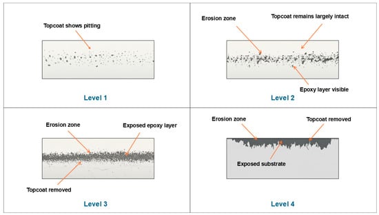
Figure 2.
Schematic representation of erosion severity levels across the blade leading edge. Adapted and redrawn from Ref. [32].
The broader erosion process can be further understood through a staged damage progression model, which delineates the evolution of wear from microscopic fatigue damage to macroscopic material loss. This model begins with the incubation stage, where no visible erosion occurs, yet internal damage accumulates in the form of microstructural strain, increased surface roughness, and nucleation of subsurface cracks [25,33]. Although mass loss is not measurable at this stage, the material is undergoing critical changes that set the stage for eventual failure. Once a threshold number of impacts is reached, the material enters the propagation stage, characterised by linear erosion rates and the onset of visible surface damage, including pitting and surface cracking [33,34]. These defects expand and deepen under continued impact loading, contributing to an accelerated rate of material removal. In the final acceleration or terminal stage, severe and localised erosion occurs. This phase is marked by the coalescence of surface pits through crack growth, leading to cratering and rapid detachment of the coating material. Once the coating is fully penetrated, the underlying substrate becomes exposed, often resulting in a sharp increase in material loss and structural vulnerability [29,35].
Experimental evidence by Rasool et al. [36] complements this staged framework by quantifying erosion progression in glass-fibre-reinforced epoxy (G10) composites. Their tests revealed a very short incubation period, with significant mass loss already occurring within the first 0–30 min of exposure. In the subsequent 30–60 min, crack propagation and delamination dominated, although an atypical decrease in net mass loss was observed. During 60–90 min, a temporary “steady state” emerged, where pit depth saturation and moisture absorption led to stabilised erosion rates and even mass gain at higher impact angles (60–90°), attributed o saline crystallisation within cracks. Beyond 90 min, however, all specimens resumed mass loss, showing a parabolic progression consistent with cumulative fatigue and pit coalescence.
While the incubation period has traditionally received the most attention in coating design and testing, the subsequent propagation and acceleration stages present equally important challenges. In particular, the development of random surface roughness patterns during these stages has significant implications for aerodynamic performance, as roughened surfaces increase drag and reduce lift efficiency [37]. These effects directly influence both the timing of maintenance interventions and the long-term operational reliability of the turbine.
One widely adopted framework for predicting erosion lifetime is the velocity–number of impacts (V–n) curve, which characterises the relationship between impact speed (V) and the number of impacts (n) required to initiate coating failure. Typically derived from rain erosion testing (RET), the V–n relationship is commonly expressed as a power law and serves as a fundamental metric for estimating the characteristic life of erosion-resistant coatings under controlled conditions. A conceptual illustration of the V–n relationship is shown in Figure 3, demonstrating the inverse relationship between impact speed and the number of impacts to failure of the framework, such as the V formulation proposed by Tempelis and Mishnaevsky [37], which normalises the number of impacts per unit area, enabling its integration into probabilistic lifetime models. In this context, the ratio is treated as a damage fraction analogous to Miner’s rule for fatigue, and its cumulative summation yields a global damage variable that governs predicted failure onset.
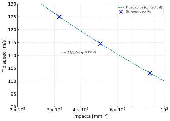
Figure 3.
Conceptual velocity–number of impacts (V–n) curve for erosion lifetime prediction. Adapted and redrawn from [37]. Experimental scatter omitted to emphasise the fitted power-law trend.
To more accurately represent real-world conditions, the V framework incorporates several critical adjustments. These include scaling factors to capture the transition from incubation to characteristic life, often express through Weibull distributions, as well as corrections for raindrop size using factors of the form . Model calibration and sensitivity analyses have highlighted the strong influence of parameters such as the Weibull shape factor and scaling multipliers on predicted lifetime, underscoring both the utility of the V approach and its sensitivity to experimental assumptions [37].
2.3. Influencing Factors: Droplet Characteristics, Impact Velocity, Environmental Conditions
The severity of raindrop erosion on wind turbine blades is influenced by a complex interplay of droplet characteristics, material properties of the blades and their coating, and ambient environmental conditions. A conceptual framework linking droplet characteristics, material properties and environmental conditions to the progression of rain erosion is presented in Figure 4. This synthesis diagram integrates the key factors discussed above, illustrating how they interact to influence the degradation pathways of wind turbine blade coatings.
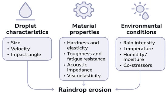
Figure 4.
Factors influencing rain erosion progression.
2.3.1. Droplet Characteristics
The erosive potential of rainfall is strongly influenced by the characteristics of individual droplets. Droplet size is a particularly significant factor, with larger droplets exerting disproportionately greater damage than smaller ones, even when normalised for total water volume [38]. This effect arises because larger droplets possess higher kinetic energy and generate greater stress upon impact [39]. Moreover, rainfall events with higher intensity tend to produce a larger proportion of these high-diameter droplets, amplifying their destructive potential [38]. In natural rain, droplet diameters typically range from 0.5 to 5 mm, while the corresponding impact velocities experienced by wind turbine blades can reach between 80 and 150 m/s [13].
Impact velocity is another critical determinant of erosion severity, as it directly governs the magnitude of impact pressure and stress transmitted into the blade surface [39]. For wind turbine blades, the dominant contributor to closing velocity is the blade tip’s rotational speed, which can reach and exceed 80 m/s [21,40]. This highlights that the kinetic energy imparted per impact is a more significant determinant of damage than simply the presence of rain. Higher impact velocities directly translate to higher kinetic energy transfer and consequently larger stress values within the coating material [7,39].
The angle of droplet impact exerts a strong influence on erosion progression, with different mechanisms dominating at different incidence ranges. At lower oblique angles (around 30–45°), shear stresses promote ductile erosion and abrasion, leading to higher mass loss in more compliant coatings. At normal incidence (90°), the full kinetic energy of the droplet is transferred to the surface, which promotes brittle fracture, severe surface damage and mass loss [7,40]. This distinction explains why some studies report higher erosion rates at oblique angles, while others observe maximum damage at normal incidence, reflecting differences in the underlying coating failure mechanisms. Notably, Groucott et al. [41] observed maximum erosion at intermediate angles of 45° to 60°, where the synergistic action of shear abrasion, brittle fracture, and lateral jetting combine to accelerate material degradation. Under longer incubation periods, the variation in volume loss across different angles becomes more pronounced, while in short incubation conditions, the effect of impact angle is comparatively negligible [40].
In cold-climate conditions, raindrops can become supercooled and partially solidify upon impact, forming freezing rain. Although the present review focuses primarily on liquid-phase raindrop erosion, it is worth noting that the transition from liquid to solid–liquid droplets alters impact dynamics. Supercooled droplets exhibit higher effective stiffness and reduced deformation on contact, producing elevated local stresses and promoting microcrack initiation within brittle coatings [42]. Upon freezing, additional thermal-contraction stresses may develop at the coating interface. These effects highlight the need for elastic or ice-phobic coatings under near-freezing conditions [42,43], but detailed discussion of icing phenomena is beyond the scope of this review.
2.3.2. Material Properties
The intrinsic properties of coating materials play a central role in determining their resistance to rain erosion. An optimal protective coating requires a balanced combination of hardness and elasticity. A reduction in stiffness and hardness, coupled with the ability to effectively dissipate impact energy, and rapidly return to the original form, is essential for enhancing durability [25]. Elastic coatings are specifically engineered to absorb impact loads without forming cracks during the early stages of erosion [23].
Since erosion is fundamentally a fatigue-driven process, toughness and fatigue resistance are equally critical. Repeated droplet impacts cause cumulative material degradation over time [44]. Coatings with higher toughness can resist the onset of surface roughening for longer durations during the incubation stage [25]. Acoustic impedance also has a notable influence on erosion, with lower acoustic impedance correlating strongly with improved performance [25]. Matching the acoustic properties of the raindrop, coating and substrate reduces stress wave reflections and attenuates damage propagation [45].
Viscoelastic behaviour further differentiates high-performance LEP coatings. Such materials often display strain rate and temperature dependent responses [25]. Coatings with relatively high viscoelastic moduli at elevated strain rates, along with strong creep recovery after impact, have been identified as desirable candidates for extended operational lifetimes [25].
2.3.3. Environmental Conditions
Environmental conditions exert both direct and indirect influences on the erosion of wind turbine blades. Rain intensity has a clear impact, with higher intensities causing greater damage than lower intensities for the same cumulative water impingement [38]. Notably, approximately 30% of annual erosion damage can occur within a mere 12 h when strong winds coincide with intense rainfall [46]. This finding underscores the fact that short-duration, high-severity weather events disproportionately contribute to long-term blade degradation.
Temperature is another important factor that can significantly alter the mechanical and erosion behaviour of polymeric coatings. Polyurethane (PU) coatings, for instance, exhibit a marked increase in erosion rate under low-temperature conditions due to changes in mechanical response near the glass-transition region (≈−5 °C to +5 °C). As the temperature decreases, reduced molecular mobility increases coating stiffness and decreases elasticity, making the material more prone to cracking and delamination. Experiments on polyurethane and thermoplastic polyurethane coatings [47,48] show that erosion rates rise sharply at sub-zero conditions, with up to nine-fold increases compared with ambient temperature. Nanoindentation results [47] revealed higher hardness and modulus but a lower hardness-to-modulus (H/Er) ratio and higher plasticity index, indicating reduced elastic recovery and greater plastic deformation environments promote a transition from elastic recovery and greater plastic deformation during impact. These findings collectively confirm that near-freezing environments promote a transition from elastic, erosion-resistant behaviour to more plastic or brittle failure modes, underscoring the importance of evaluating coating performance under cold-climate conditions.
Furthermore, humidity and surface moisture also contribute to degradation, promoting processes such as coating delamination from the substrate [49]. In addition, turbine blades are subjected to co-stressors including ultraviolet (UV) radiation, thermal cycling from temperature fluctuations, and salt induced corrosion in marine environments [21]. These factors not only act independently to deteriorate coatings but can also exacerbate the effects of rain erosion. Rasool et al. [50] provide further evidence of this synergistic degradation, showing that glass-fibre-reinforced epoxy (GFRE) composites exposed to saline and acidic rain environments undergo distinct erosion mechanisms and accelerated damage. Acidic rain was found to cause higher mass loss and severe degradation features such as blistering, delamination, pitting, and stress-corrosion cracking, while saline exposure promoted swelling, fibre–matrix debonding, and salt deposition. Together, these findings confirm that chemical co-stressors can interact with raindrop impact to intensify erosion progression and compromise the long-term durability of blade materials.
The degradation of wind turbine blades is a multi-faceted process in which environmental factors not only impose mechanical stresses but also alter the intrinsic properties of the coating materials. For example, low temperatures can cause PU coatings to shift from a ductile to brittle response, thereby increasing their vulnerability to impact damage [47]. Such interactions create a reinforcing feedback loop in which environmental exposure both initiates erosion and reduces the coating’s capacity to withstand it. Consequently, coating design and material selection must be tailored to the specific meteorological and environmental conditions of a given installation site. The fact that a substantial portion of damage can occur in a very short time span, and that regional climatic variations are significant, demonstrates the limitations of generic protection strategies. Coating solutions should therefore be optimised not for average conditions, but for extreme, high-impact events that are most responsible for cumulative degradation. A summary of key experimental studies highlighting the quantitative influence of these parameters on raindrop erosion progression is presented in Table 1.

Table 1.
Summary of experimental studies on influencing factors of erosion severity.
2.4. Mechanical and Operational Implications
Raindrop erosion initiates a progressive, fatigue-driven degradation process that extends beyond superficial coating loss, undermining the mechanical integrity, fatigue life, and operational stability of the blade. Although a single droplet impact induces stress below the material yield strength, repeated high-velocity impacts cumulatively cause cracking, delamination, and coating failure [20]. Once the protective layer is breached, the exposed composite undergoes direct impact and environmental degradation, accelerating structural compromise [13].
Erosion also modifies the vibrational and aerodynamic characteristics of the blade. Progressive surface roughening alters modal stiffness and flow patterns, prompting load imbalances and increased aeroacoustics noise due to boundary layer disturbances [51,52]. As the turbine compensates via pitch adjustments, this feedback loop between aerodynamic inefficiency and mechanical overstressing amplifies fatigue and reduces service life [53].
From an operational standpoint, analytical studies highlight that coating failure and LEE significantly increase maintenance and downtime costs, thereby elevating the levelised cost of energy (LCoE) and reducing the annual energy production (AEP) of wind farms [30,54]. In some installations, coating degradation has been observed after only 4 years [39], far shorter than the intended 20–25-year design life [12,55]. Globally, operation and maintenance (O&M) costs for onshore wind farms exceeded USD 15 billion in 2019, with more than half attributed to unplanned repairs [39]. Erosion-related repairs typically require 260–340 h per turbine, resulting in extended downtime and reduced AEP. The net present value (NPV) of the combined losses and repair costs is estimated at 2–3% of the turbine’s gross lifetime energy yield [55], with total lifetime expenditures reaching up to £1.3 million per turbine [12]. Preventive maintenance remains substantially more cost-effectiveness, potentially lowering lifetime maintenance costs by a factor of 11.8 compared with corrective measures [39]. Consequently, LEE is not merely a surface durability issue but a critical factor influencing turbine reliability, energy performance, and long-term sustainability.
3. Protective Coating Technologies for Wind Turbine Blades
Protective solutions for wind turbine blades are classified based on composition and application method into polymeric, hybrid and alternative systems, as illustrated in Figure 5.
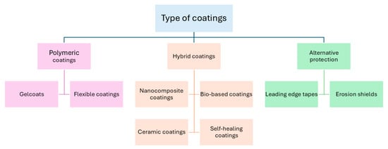
Figure 5.
Classification of protective coatings.
3.1. Requirements for Anti-Erosion Coatings
The development and selection of protective coatings for wind turbine blades are guided by stringent performance requirements due to harsh operational environments and the critical importance of blade integrity. Foremost among these is high erosion resistance itself, the primary function of the coating. This involves withstanding repeated high-velocity impacts from raindrops and airborne particles without significant degradation or material loss. Equally important is strong adhesion to the underlying substrate, as poor adhesion can result in delamination and subsequent exposure of the blade structure to damage [21]. The application of a primer layer beneath the main coating has been shown to enhance adhesion, reduce the risk of separation, and minimise application-related defects [45].
Flexibility and elasticity are also essential. The relationship between coating elasticity and surface wettability also plays a critical role in impact dynamics. Alizadeh et al. [56] investigated the influence of substrate elasticity on droplet impact using fluorinated poly(dimethylsiloxane) (PDMS) surfaces with varying elastic moduli. Their results showed that on flat hydrophobic substrates, softer materials dissipated more impact energy through viscoelastic deformation, reducing droplet retraction and thereby increasing the final contact area. However, on textured superhydrophobic surfaces, impact dynamics remained unaffected by substrate elasticity, preserving high water repellence and minimal adhesion. Such insights emphasis that the broader potential of elastic hydrophobic or superhydrophobic coatings to balance impact-energy absorption with low surface adhesion, an advantageous combination for mitigating rain erosion and preventing surface icing.
Furthermore, coatings must absorb and distribute the high kinetic energy imparted by droplet impacts while avoiding permanent deformation or cracking [25]. An effective coating should therefore combine energy-damping capacity with rapid recovery to its original shape [25]. In addition, coatings must demonstrate stability against UV radiation, chemical attack, and temperature fluctuations. Wind turbine blades are subject to solar exposure, expansion and contraction under varying temperatures, and corrosive environments, particularly offshore [21]. For instance, low ambient temperatures can shift polymers such as polyurethane from ductile to brittle behaviour, thereby reducing their resistance to erosion [47]. From a practical perspective, ease of application and repair is also an operational requirement; coatings must be compatible with efficient manufacturing methods and allow straightforward in situ repairs to minimise turbine downtime [57].
Beyond these primary criteria, several additional material properties play an important role in erosion resistance. A low acoustic impedance has been shown to improve coating durability, as it governs how stress waves propagate within the material [21]. Effective acoustic matching between the raindrops, coating, and substrate significantly extends erosion lifetime. Modern coatings often leverage viscoelastic properties because of their unique ability to absorb and dissipate the energy from rain droplet impacts, which is crucial for preventing erosion. Unlike purely elastic materials, which transfer energy back to the material, viscoelastic materials can experience a rapidly increasing stress field and then relax, dissipating the impact energy as heat. This makes them highly effective at withstanding the repeated, high-rate pressure of water droplet collisions at high speeds, which is a major cause of blade damage and failure [45].
A high Poisson’s ratio has been identified as a critical property for enhancing erosion resistance, as it governs how impact energy from raindrops is managed and distributed within the coating. Coatings with higher Poisson’s ratios experience reduced overall stress magnitudes during impact, which directly correlates with longer lifetimes by diffusing the applied energy rather than concentrating it at specific points. This property also alters energy partitioning, directing most of the impact energy into shear and Rayleigh waves while minimising the propagation of destructive compressive shockwaves that initiate surface damage. As such, coatings with low stiffness, low density, high strength, and a high Poisson’s ratio are considered optimal, since this combination enables effective absorption and dissipation of impact energy while resisting crack formation and surface degradation [58].
Ultimately, erosion resistance cannot be attributed to a single property such as hardness. Instead, it requires a holistic approach to material design that balances mechanical, acoustic, and chemical properties, with particular emphasis on viscoelasticity and adhesion. A coating that is highly rigid but lacks flexibility or strong adhesion may fail prematurely through cracking or delamination. Furthermore, protective coatings are typically applied as multi-layer systems comprising a primer, filler, and topcoat over the composite substrate [21]. The long-term performance of such systems depends not only on the intrinsic properties of individual layers but also on interfacial adhesion and acoustic compatibility across the coating stack. Mismatched impedance or weak bonding at interfaces can result in stress wave reflection and premature delamination, even when the coating materials themselves exhibit high erosion resistance [21].
The durability of a coating and its anti-erosion performance are intrinsically connected. Durability reflects the coating’s capacity to retain its functional integrity under prolonged mechanical and environmental loading, whereas anti-erosion performance refers specifically to resistance against impact-induced material loss. In practical terms, a coating that remains durable over time will preserve its anti-erosion capability, as both depend on the stability of the coating’s mechanical cohesion, interfacial adhesion, and chemical structure [21,44,49]. When degradation processes such as ageing, UV exposure, or microcrack propagation compromise these attributes, the coating’s ability to dissipate impact energy decreases and erosion accelerates [49]. Coatings that maintain flexibility, adhesion, and barrier integrity, however, sustain their protective performance and extend the service lifetime of the blade surface. Therefore, durability can be viewed as the governing envelope within which anti-erosion behaviour is maintained throughout exposure.
3.2. Conventional Coating Materials
Historically, and continuing into present practice, polymeric materials have formed the backbone of protective coatings for wind turbine blades. Among these, PUs remain the most widespread conventional coating material for wind turbine blades [44,59,60]. Polyurethane elastomers bridge the gap between polymers and vulcanised rubbers, offering high elasticity, load capacity, and tear resistance [61]. Their inherent flexibility and toughness enable them to absorb and redistribute impact energy from raindrops, which essential for mitigating LEE [62]. From a manufacturing perspective, PU resins also enhance production efficiency through faster curing times and more favourable processing parameters, leading to shorter blade production cycles and reduced energy consumption [62]. As a result, PU resins are increasingly viewed as attractive alternative to traditional epoxy resins. In addition, PU-based topcoats are valued for their mechanical strength, ultraviolet and thermal stability, long-term damping capacity, and chemical resistance, making them the most common coating system in the applied to turbine blades [63].
Despite these advantages, PUs are not without limitations. Their erosion resistance is strongly influenced by temperature fluctuations [64]. At elevated temperatures, friction and deformation hysteresis generate internal heating within the worn surface layer, reducing cohesive energy in the subsurface and weakening molecular bonds. This promotes crack initiation, delamination, and accelerated material loss due to insufficient heat dissipation [61]. Conversely, at low ambient temperatures, PUs undergo a transition from ductile to brittle failure, resulting in higher erosion rates as cracks propagate more rapidly [47]. Thus, both extremes, softening at high temperatures and embrittlement at low temperatures, compromise the erosion resistance of PU coatings, underscoring the necessity of accounting for environmental thermal conditions in their design and application.
Epoxy-based coatings are also utilised, often as the matrix material for the composite blades themselves [8]. They are valued for their adhesion, chemical resistance, and durability [65,66], and can be integrated into multifunctional systems as anti-icing coatings [63]. However, their rigidity and brittleness make them prone to cracking and delamination under repeated impacts [67], and their wear resistance remains limited [68]. Moreover, susceptibility to UV degradation undermines their long-term performance [66].
The performance gap of conventional solutions, particularly PUs, presents a major challenge. Despite their widespread use, these coatings often fail prematurely, with reported lifetimes ranging from as little as 4 years to 6–8 years in service, far below the 25 to 35 years design life of modern turbines [44]. Such premature failures necessitate costly maintenance and repair interventions, directly undermining the economic viability of wind power projects. This shortcoming makes clear that while conventional coatings provide a baseline level of protection, they lack the long-term resilience required for the current generation of large, high-speed turbines, particularly in offshore environments where exposure is most severe.
The temperature sensitivity of PUs illustrates the critical importance of material-environment interactions. Their tendency to transition from ductile to brittle behaviour at low temperatures [47] and to lose cohesive integrity at elevated temperatures due to internal heating [61] demonstrates that materials performing well under laboratory conditions may degrade rapidly under harsh field environments. This emphasises the importance of designing and selecting coatings not solely for their intrinsic erosion resistance, but also for their stability across the full spectrum of operational conditions, including temperature extremes, UV, humidity, and other environmental co-stressors. Only by ensuring that materials maintain their properties under real-world exposure can coatings deliver the long service lifetimes required for sustainable and cost-effective wind energy generation.
3.3. Emerging Coating Technologies and Advanced Materials
This clear performance gap of conventional coatings, particularly PUs and epoxies, has spurred growing research into emerging coating technologies advanced material systems, often leveraging nanotechnology and bio-aspiration, which aim to deliver enhanced erosion resistance and long-term durability under the conditions faced by modern wind turbines.
3.3.1. Nanocomposite Coatings
Nanocomposite coatings have shown potential as effective class of materials for improving the erosion resistance of wind turbine blades. A key advantage lies in their ability to leverage the exceptional properties of nanoscale fillers, which improve mechanical robustness, modify stress distribution under impact, and in some cases introduce multifunctional performance.
Carbon-based nanofillers such as carbon nanotubes (CNTs) and graphene are particularly effective. Dashtkar et al. [40] emphasise that CNTs, when incorporated into sol–gel matrices, significantly enhance electromechanical properties and microhardness by mechanisms such as crack bridging. Similarly, graphene provides remarkable strength, stiffness, and thermal conductivity, which can be harnessed to develop coatings with improved toughness, corrosion resistance, and hydrophobicity.
Beyond mechanical reinforcement, nanocomposites can deliver multifunctional properties. Cui et al. [69] developed a polyurethane-based nanocomposites film with a unique sandwich structure that simultaneously offers erosion resistance and de-icing capability. Incorporating CNTs and graphene nanoplatelets enabled both rapid electrothermal heating, achieving 96.5 °C within 300 s at 9 V, and photothermal performance under simulated solar intensity. This dual functionality, combined with high tensile strength (48.5 MPa) and excellent elongation at break (795%), demonstrates the potential of nanocomposite films to address multiple operational challenges simultaneously. Recent studies [70] have emphasised multifunctional photothermal and electrothermal coatings that integrate passive anti-icing and active de-icing strategies, offering efficient and durable protection for outdoor applications such as wind turbine blades.
Hybrid nanoreinforcement strategies further amplify erosion resistance. Johansen et al. [71] reported that polyurethane coatings reinforced with graphene nanoplatelets (GNPs) and silica-based sol–gel exhibited lifetimes up to thirteen times longer than pure PU coatings. At high impact velocities (150–172 m/s), the hybrid nanocomposites required substantially more impacts to initiate cracking, delamination, and material loss compared to conventional PU. This performance improvement was attributed to effective stress wave scattering and enhanced dispersion of nanoparticles, which together improved the fatigue resistance and mechanical integrity of the coating.
Similarly, Ibrahim and El-Tayeb [72] demonstrated that combining nano-silica and nano-alumina fillers in hybrid coatings could reduce erosion wear by up to 99% compared to uncoated GFRP. The synergistic interaction between the nanoparticles produced a ductile erosion response and suppressed crack formation and propagation. Importantly, this study highlighted that minimising nanoparticle agglomeration is critical, as smaller, well-dispersed particles exhibited superior erosion resistance relative to larger, clustered counterparts.
Across recent studies on nanocomposite coatings, several converging opportunities and challenges emerge. Collectively, the findings point to significant potential for nanomaterials to extend coating lifetimes, impart versatility, and address persistent limitations of conventional systems. An illustration for this is sol–gel-derived coatings incorporating carbon nanomaterials, which provide thin, lightweight, and multifunctional protection with enhanced hardness and crack resistance [40]. Similarly, polyurethane-based nanocomposite films demonstrate the feasibility of combining anti-erosion and rapid de-icing in a single system, a critical advancement for turbines in cold climates [69]. Nanoengineered hybrid systems further underscore the potential for substantially extending coating lifetimes compared to conventional PU [71]. Hybrid silica–alumina systems also show dramatic reductions in erosive wear, shifting failure mechanisms from brittle to ductile responses [72].
Despite these promising advances, the challenges are equally consistent across studies. Nanoparticle agglomeration remains a central obstacle, as poor dispersion compromises mechanical and functional performance [40,72]. Processing complexity and the need for precise control during fabrication, whether through sol–gel chemistry, hot pressing, or hybrid dispersion, pose scalability issues for industrial adoption [69,72]. Cost and long-term testing also remain underexplored, with few studies addressing the economic feasibility or durability of these coatings over 20- to 30-year turbine lifespans; moreover, property mismatches between multi-layer systems, residual stresses, and environmental factors such as heat accumulation or UV exposure could undermine performance in operational conditions [40,71]. Together, these insights underline that while nanocomposite coatings represent a promising frontier for anti-erosion protection, realising their industrial application will require advances in nanoparticle functionalisation, large-scale processing, and long-term durability validation.
3.3.2. Bio-Based Coatings
Research on bio-based nanocomposite coatings for wind turbine blade protection remains relatively limited, yet emerging evidence points to potential directions. Mishnaevsky et al. [49] reports that nanocellulose fibres, owing to their high strength, stiffness, and low density, are attractive reinforcements for bio-based polymers. Computational modelling indicated that the reinforcement effect is strongly concentration-dependent, with only high nanocellulose contents producing a measurable reduction (~10%) in local stresses near voids, whereas dilute concentrations showed negligible benefit. Experimental validation from [73] further confirmed that cellulose-based reinforcements can improve coating performance by up to 70%, directly addressing the challenge of LEE. These findings suggest that nanocellulose, while requiring careful optimisation of loading levels, has significant potential as a sustainable reinforcement strategy for anti-erosion coatings.
Complementing this, recent industrial developments have introduced bio-based PU coatings specifically designed for leading-edge protection. For example, Mitsubishi Chemical Group has developed the BENEBiOLTM polycarbonate diol system, incorporating up to 93% biomass content, which has been reported to deliver outstanding erosion resistance and reduced maintenance requirements in harsh environments, while offering durability and chemical resistance comparable to, or surpassing, conventional petroleum-derived products [74].
3.3.3. Ceramic Coatings
Ceramic-based coatings represent another important strategy for improving the erosion resistance of wind turbine blades. Pathak et al. [63] investigated epoxy matrices reinforced with nanoparticle fillers of aluminium oxide (Al2O3), zirconium dioxide (ZrO2), and cerium dioxide (CeO2), synthesised through a solution combustion method. Their results demonstrated that ZrO2- and CeO2-reinforced coatings significantly outperformed both neat epoxy and unmodified GFRP substrates, reducing erosion by 60–65% compared to epoxy and 79–82% compared to bare GFRP. The coatings generally exhibited a ductile erosion mechanism, with minimum wear observed at 90° impact angles. Importantly, mechanical characterisation revealed a direct correlation between nanoindentation properties (H3/E2) and erosion resistance, suggesting that improved plastic deformation resistance optimises performance. Moreover, tensile properties also influenced erosion response, with a higher strength and modulus associated with better resistance, while greater elongation correlated inversely. Pathak et al. [63] also emphasised that their synthesis and application approach, which involved solution combustion synthesis and spray deposition, was low-cost and scalable, highlighting its practical potential for industrial adoption.
Further insight is provided by the volume [75], which discusses perspectives on ceramic erosion behaviour, particularly plasma-sprayed oxides. One study in this collection examined alumina- and calcia-stabilised zirconia coatings, which displayed composite erosion behaviour with peak damage occurring at 45° impact angles, diverging from the typical ductile (low angle) or brittle (90°) profiles. This response was attributed to the lamellar microstructure characteristic of plasma-sprayed coatings. Furthermore, hardness and porosity were identified as critical factors in determining erosion resistance, with harder and denser coatings exhibiting superior performance. Other chapters emphasise the broader durability of zirconia coatings, particularly in high-temperature and high-stress environments such as internal combustion engines, where their thermal shock resistance and erosion durability are well established. Together, these findings underline the versatility of ceramic coatings in protective applications while also drawing attention to microstructural features and processing routes that critically shape their resistance to erosive wear.
3.3.4. Self-Healing Coatings
Self-healing coatings offer a promising approach to extend the service life of wind turbine blades by enabling in situ repair of microcracks and erosion damage. According to Dashtkar et al. [40], microcrack formation is a major challenge in structural polymer composites. Incorporating self-healing functionality improves durability, safety, and longevity. These mechanisms are typically categorised as capsule-based or vascular-based, each varying in damage repair capacity, repeatability, and recovery efficiency.
Keller et al. [76] conducted a direct experimental evaluation of capsule-based self-healing strategies applied to both elastomeric and epoxy coatings subjected to solid particle erosion. Their results highlight the stark contrast in healing performance between systems. The elastomeric poly(dimethyl siloxane) (PDMS)-based coating, despite incorporating a two-part microencapsulated healing chemistry, exhibited poor healing efficiency due to the high viscosity (~5200 cP) of the resin and slow reaction kinetics. Consequently, the supposed self-healing specimens performed worse than neat PDMS controls, showing 47% higher mass loss under erosive testing. Microscopic analysis confirmed that the viscous resin failed to flow from ruptured capsules, resulting in negligible self-healing activity.
Conversely, the epoxy-based system demonstrated clear success. In this case, hexamethylene diisocyanate (HDI) encapsulated in a PU shell acted as a low-viscosity healing agent, curing upon contact with atmospheric moisture. When subjected to 90° erosion testing, the self-healing epoxy coating reduced mass loss by nearly 300% compared to a non-healing capsule-filled control. The healed specimens approached the performance of neat epoxy, with only 43% higher mass loss, whereas the non-healing control deteriorated by 337%. SEM analysis further revealed extensive healed regions centred around ruptured capsules, confirming the effectiveness of the healing mechanism.
Together, these studies underline the potential and limitations of self-healing coatings. While elastomeric systems may be constrained by resin viscosity and kinetic barriers, epoxy-based approaches using reactive, low-viscosity agents show significant promise in mitigating erosion damage. The challenge remains in translating these findings into repeatable, scalable systems suitable for long-term wind turbine blade applications.
These studies on nanocomposite, bio-based, ceramic, and self-healing coatings illustrate the breadth of emerging material strategies for enhancing erosion resistance in wind turbine blades. Nanocomposites dominate the current research landscape due to their versatility and demonstrated multifunctionality, while bio-based, ceramic, and self-healing coatings remain at an earlier stage of development with comparatively fewer studies. This imbalance highlights the strong research momentum behind nanocomposites but also underscore the need for further exploration of alternative material systems. Table 2 summarises the reviewed literature across these categories, emphasising the coatings systems, base matrices, application methods, and key findings.
Table 2.
Summary of recent studies on advanced coating systems for wind turbine blades.
3.4. Coating Application Methods
The application method plays a critical role in determining the durability and performance of wind turbine blade coatings. Literature broadly distinguishes between in-mould and post-mould applications, with alternative approaches such as sol–gel processes, tapes, and erosion shields also being explored.
In-mould coatings (gelcoats) are applied during blade manufacturing and are typically composed of materials similar to the composite matrix, such as epoxy or polyester. They offer cost-effectiveness by integrating coating deposition into the fabrication process and can provide good acoustic impedance, thereby moderating stress transfer at the blade surface. Cortes et al. [21] observed that semi-cured-in-mould coatings performed better than fully cured ones, delaying the incubation period and reducing erosion rates through improved adhesion and reduced delamination. However, multiple studies highlight their brittleness and tendency to suffer from surface cracking and damage under erosive loading [12,13,21].
Post-mould coatings are applied after blade fabrication, most commonly by spraying or painting flexible polyurethane-based layers. These coatings are widely used for LEP and allow more versatility in material choice compared to in-mould systems. Cortes et al. [21] reported that elastomeric post-mould coatings outperformed rigid in-mould gelcoats in rain erosion testing. The performance of LEP systems can be further improved with multilayer architectures incorporating putty and primer layers; the addition of a primer significantly improved adhesion and reduced delamination risks. A schematic representation of the coating layer is shown in Figure 6. Similarly, Keegan et al. [13] noted that post-mould coatings provide flexibility and repairability, making them well suited for both initial protection and maintenance. Nonetheless, Herring et al. [12] pointed out challenges associated with manual application, such as surface defects, poor adhesion due to contamination, and difficulties in field repairs under uncontrolled conditions.
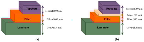
Figure 6.
(a) LEP coating system incorporating a filler layer; (b) modified system with an added primer layer to strengthen bonding with the substrate. Redrawn from [21].
Beyond conventional coating systems, sol–gel techniques have emerged as an alternative, offering energy-efficient, low-temperature deposition of thin films (0.01–5 µm). Dashtkar et al. [40] described several sol–gel deposition methods, including dip, spin, spray, flow, capillary, and roll coating, each suited to different substrate geometries. Sol–gel films exhibit uniformity and precision, although their thinness raises questions about long-term protection under severe erosive conditions.
In addition to liquid-applied coatings, LEPs and erosion shields are increasingly used. Kinsley et al. [77] reported that tapes, adapted from the aerospace sector, are designed to absorb impact energy but face challenges in adhesion, especially around curved blade tips. Herring et al. [12] elaborated that tapes, while manufactured with high quality, can fail through disbondment caused by trapped air bubbles or poor adhesion. Erosion shields, also manufactured in controlled environments, mitigate some of these issues by being custom-fitted and affixed with adhesives. However, stiffness mismatches can cause bond failure, indicating the importance of adhesive quality. Integrated erosion shields, proposed as a co-cured or co-bonded solution during blade manufacturing, aim to overcome these drawbacks by providing a smooth, permanent barrier against erosion, although challenges remain in managing stiffness transitions [12].
Synthesising these findings, these studies show that no single application method provides a comprehensive solution. In-mould gelcoats offer manufacturing efficiency but are brittle, while post-mould flexible coatings and multilayer systems provide superior protection but are vulnerable to adhesion failures. Sol–gel methods deliver precision and uniformity but require further durability validation, whereas tapes and shields present scalable alternatives with ongoing challenges in bonding reliability. This spectrum of findings illustrates the importance of tailoring application methods to balance manufacturing feasibility, mechanical performance, and long-term durability under field conditions.
4. Experimental Testing Methodologies for Raindrop Erosion
4.1. Laboratory Testing Methods
A wide range of testing facilities has been employed in the literature [71,78,79,80,81,82]. According to [83], rain erosion test setups can be classified based on two main criteria: whether the target specimen is stationary or in motion, and whether the system produces single or multiple droplet impacts. The configuration of these four possible combinations is left to the researcher’s discretion, leading to a variety of innovative experimental designs. Figure 7 illustrates the main types of erosion facilities and their respective classifications.
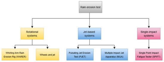
Figure 7.
Overview of common erosion test configurations used for rain erosion studies.
4.1.1. Whirling Arm Rain Erosion Test
The whirling arm rain erosion test (RET) is the most widely used and standardised method for evaluating LEP systems, formalised under DNV-RP-0171. In this setup, coated specimens are mounted on a rotor and accelerated through an artificial rain field generated by arrays of drop-dispensing needles. Figure 8 shows a simplified schematic of the whirling arm rain erosion rig used for coating erosion evaluation. The method provides accelerated testing by increasing rotational velocities, rainfall intensity, and droplet diameters beyond natural values. Performance is often assessed using V-n curves, which describe the number of impacts to failure as a function of droplet velocity. Kinsley et al. [77] emphasised its value in producing controlled and repeatable data but noted critical shortcomings, including unrealistic constant droplet sizes, the absence of dry recovery periods, and inadequate representation of viscoelastic material responses. Similarly, Bech et al. [84] confirmed its utility of systematic studies on drop size effects but raised concerns regarding extrapolation of accelerated data to operational ranges, high costs of multi-size testing, and limited field validation.
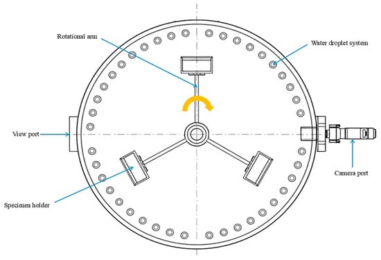
Figure 8.
Schematic top-view illustration of the whirling arm rain erosion rig, showing the rotating arm, specimen holder, and artificial rain field used to simulate droplet impacts. Adapted and redrawn from Ref. [20].
4.1.2. Single Point Impact Fatigue Tester
The Single Point Impact Fatigue Tester (SPIFT) offers an alternative approach by subjecting coatings to repeated high-velocity impacts at a single location using compliant nitrile rubber projectiles as shown in Figure 9. This recently developed technique employs an electropneumatic firing system that propels balls using compressed air. The exit velocity is influenced by factors such as barrel length, air pressure, ball mass, and nozzle diameter. Balls are supplied to the firing chamber from a vibrating magazine hopper through gravity feeding [85]. The method allows precise control of impact velocity, impact frequency, and loading history, and provides accelerated testing conditions up to 173 m/s. The use of rubber projectiles produces a deformation response closer to raindrop impacts than hard-particle methods. Johansen et al. [71] reported that SPIFT enables detailed observation of damage initiation, growth, and viscoelastic heating effects through high-speed imaging and thermography. However, SPIFT departs from natural rain erosion by concentrating impacts on a single point rather than distributing them over a surface, and the complexity and cost of the equipment pose additional limitations.
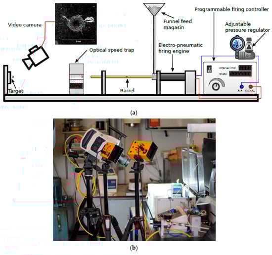
Figure 9.
(a) Schematic of the SPFIT configuration; (b) high-speed imaging system used to capture the ball impacts. Reprinted from Ref. [71] with permission.
4.1.3. Water Jet Impingement
Water jet impingement testing represents a more accessible laboratory-scale alternative, where a high-pressure nozzle produces either continuous or pulsating flows directed at a coated sample, producing repeated high-speed impacts on the exposed surface. These impacts generate intense pressures and transmit energy into the material through stress wave propagation. The resulting cyclic impact loading over time leads to fatigue accumulation and eventual material failure [86]. Pulsating jets are particularly attractive because they produce water hammer effects and generate erosion crack morphologies that closely resemble those observed under natural rain. Figure 10 presents three approaches used to create pulsating flow: a disk-cutting device and active/passive acoustic pulsating nozzles. As illustrated in Figure 11, Wu et al. [86] developed a pulsating water jet tester for accelerated rain erosion evaluation based on a passive acoustic pulsating nozzle. Their experiments identified distinct flow regimes as presented in Table 3, with the pulsating flow zone producing erosion morphologies most representative of those observed on reference blade coatings. Within this zone (approximately 45–75 mm from the nozzle), repeated high-frequency impacts generated crater-shaped damage accompanied by cracking and fragment detachment, consistent with fatigue-driven failure and lateral jetting effects. The very high impact frequency, on the order of 7500 impacts/s, promoted rapid fatigue accumulation and accelerated coating degradation. Microscopic analysis also revealed inter-layer weaknesses, where insufficient adhesion between the primer and topcoat resulted in crack tunnelling and partial layer detachment.
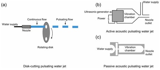
Figure 10.
Three methods to produce pulsating flows (a) a disk-cutting device (b) active acoustic pulsating nozzle (c) passive acoustic pulsating nozzle. Reprinted from Ref. [86] with permission.
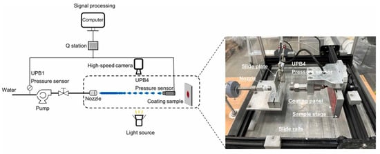
Figure 11.
Pulsating water jet setup designed for accelerated rain erosion evaluation of wind turbine blade coatings. Reprinted from Ref. [86] with permission.
Table 3.
Classification of flow zones based on the distance from the nozzle and corresponding flow structure [86].
Wu [82] further demonstrated that the pulsating jet configuration provides a cost-effective and easy-to-operate setup capable of substantially shortening test duration through extremely high impact frequencies. Its ability to reproduce realistic erosion features makes it valuable for mechanistic investigations and early-stage material screening. However, its correlation with industrial whirling arm rain erosion tests remains limited, as droplet size, shape, impact frequency, and overall flow behaviour differ considerably from natural rain conditions. Moreover, rapid material loss can mask the incubation stage, and the combined influence of multiple parameters may lead to failure mechanisms that deviate from those observed in field exposures. Consequently, while the pulsating jet is advantageous for controlled laboratory studies, its applicability for direct performance validation against operational conditions remains constrained.
Collectively, these laboratory methods illustrate the trade-offs between standardisation, precision and realism in rain erosion testing. The whirling arm RET remains the industry standard and primary method for evaluating commercial blade coatings. Its artificially generated rain field closely replicates real operating conditions, as it simulates a blade moving through a field of randomly distributed droplets. The method is widely accepted within the wind industry, complying with standards such as ASTM G73-10 [87] and DNV-RP-0171 [88], which makes its results essential for certification and comparative evaluation. Moreover, it provides valuable lifetime data by producing V-n curves that define the time to failure and enable erosion lifetime prediction and maintenance planning [77]. In contrast, SPFIT and water jet rigs serve as complementary laboratory tools for coating screening and erosion mechanism studies. They provide detailed information on impact dynamics and fatigue-induced crack initiation, making them particularly valuable for research and material development aimed at improving energy dissipation and crack resistance. However, their impact conditions differ markedly from real rainfall. A direct correlation between discrete water jet results and those from the whirling arm rig is generally not possible because the erosion mechanisms are fundamentally different. Water jet setups are best suited for rapid, preliminary screening of new coating formulations, while the whirling arm rig remains indispensable for realistic performance ranking and validation [89]. The advantages and disadvantages of these methods are presented in Table 4.
Table 4.
Summary of erosion testing equipment: advantages and disadvantages.
4.2. Characterisation Techniques for Erosion Damage
A wide range of characterisation techniques has been developed to evaluate erosion-induced damage at different spatial scales and depths. These methods can be broadly categorised into surface microstructure analysis and thickness microstructural examination. Figure 12 summarises the hierarchy of these approaches, highlighting the transition from surface-focused mapping to subsurface tools used for assessing coating degradation.
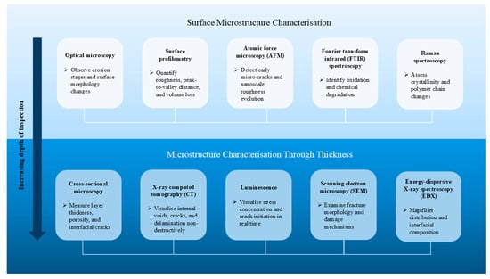
Figure 12.
Summary of characterisation techniques used for rain erosion studies.
4.2.1. Surface Microstructure Characterisation
Quantitative surface mapping is essential for linking rain-erosion damage to coating roughness evolution and stress concentration. The IEA Wind Task 46 [90] documents key approaches, notably optical microscopy and surface profilometry, for generating 2D/3D height maps that quantify roughness and volume loss. High-magnification optical microscopy enables non-destructive observation of successive erosion stages on a single specimen, allowing the mechanisms of material loss to be monitored in real time. Using this approach, Zhang et al. [89] compared two coatings and reported distinct degradation modes, one governed by epoxy matrix failure and the other initiated by surface defects that led to crack formation and material detachment.
Optical profilometry is increasingly used to quantify erosion progression through repeated surface scans that measure height variations, roughness parameters, and mass loss [91]. Tobin et al. [92] employed confocal laser scanning microscopy (CLSM) to track the incubation period of rain erosion, demonstrating that continuous 2D and 3D scanning across time stages can effectively capture the transition from surface roughening to material removal.
Atomic force microscopy (AFM) captures nanoscale roughness evolution and provides early indicators of microcracking in polymeric topcoats. AFM has been used to track fine roughness evolution and morphological changes in polymeric topcoats after rain erosion exposure, offering sensitivity to early-stage damage that may precede visible pitting [40]. Zhang et al. [93] further demonstrated that tapping-mode AFM was effective in tracking the evolution of surface topology throughout the erosion testing by analysing piezo displacement data and cantilever-deflection.
Spectroscopy methods such as Fourier transform infrared (FTIR) and Raman spectroscopy are widely used for surface characterisation due to their non-destructive nature and molecular sensitivity to polarizable bonds. Both techniques provide complementary information on chemical structure and bonding characteristics. FTIR detects vibrational modes associated with dipolar functional groups, while Raman spectroscopy is more sensitive to polarisable bonds. Together, they are valuable tools for identifying or monitoring chemical changes within coating materials, such as polymer degradation, crosslinking behaviour, or variations in resin chemistry following erosion exposure [90].
4.2.2. Microstructure Characterisation Through Thickness
Assessing damage beneath the surface is essential for understanding incubation, crack nucleation at interfaces, and delamination. Cross-sectional microscopy remains a workhorse: samples are sectioned, potted, polished, and images to measure layer thickness, porosity, and void distributions [94].
X-ray Computed Tomography (CT) is a radiographic method that irradiates a sample with X-rays, detecting transmitted radiation according to the differing absorption properties of materials and defects. This approach offers significantly higher resolving power than conventional radiography, enabling detailed imaging at the level of individual fibres and allowing multiple 2D images to be compiled into a 3D reconstruction of the specimen [91]. X-ray CT provides non-destructive visualisation of internal features such as air inclusions, interfacial defects, and growing cracks, with repeated scans on the same specimen allowing for the monitoring of crack growth kinetics over time [95]. Comparable investigations employing tomography to examine damage mechanisms associated with leading edge erosion have also been reported in the literature [94,96]. However, practical limitations include the low contrast achieved with low-density polymeric materials, the trade-off between specimen size and achievable resolution, and the fact that multi-hour scan times are often required for high-fidelity datasets.
Luminescence refers to the emission of light resulting from non-thermal excitation processes such as chemical reactions, electrical stimulation, or mechanical stress, distinguishing it from thermal radiation or incandescence [97]. Within this broad category, mechanoluminescence describes light emission triggered by mechanical actions including stress, strain, or fracture. This enables direct visualisation of stress concentrations and microcrack formation as emitted light, providing a non-destructive means to map damage evolution in real time during mechanical loading [98].
Scanning electron microscopy (SEM) and energy-dispersive X-ray spectroscopy (EDX) are widely employed for post-mortem characterisation, offering high-resolution visualisation of failure mechanisms and local chemical composition. SEM is particularly useful for tracing crack paths, matrix damage, and interfacial failure zones after erosion testing, through its in situ nature limits real-time observation [54]. Johansen et al. [71] demonstrated the capability of SEM to distinguish microstructural differences among polyurethane-based coatings with various nanofillers, correlating reduced cavity formation and delayed cracking with improved erosion resistance. When combined with EDX, elemental mapping enables identification of fillers, interphases, and contaminant-driven defects, though the requirement for conducive coatings and vacuum conditions can increase preparation time and introduce artefacts [71,90].
4.3. Correlation Between Laboratory and Field Testing
Establishing a robust correlation between laboratory rain erosion tests and field performance of wind turbine blade coatings remains one of the most persistent challenges in the field. Laboratory methods such as the whirling arm rig, SPIFT, and water jet impingement devices provide controlled and accelerated conditions for material screening, but they cannot fully replicate the highly variable and synergistic environmental stresses experienced by blades in operation [82].
4.3.1. Parameter Comparison
A key source of discrepancy lies in the differences between laboratory and field-testing parameters. Laboratory devices can achieve impact velocities ranging from 90 to 225 m/s in whirling arm rigs and up to 350 m/s in water jet testers, while actual blade tip speeds in the field typically fall between 70 and 150 m/s, depending on rotor size [21,82]. Droplet sizes also differ, with lab-generated droplets usually fixed at 2.2 to 3.5 mm diameter, whereas natural raindrops exhibit a broad distribution and deform aerodynamically before impact. This discrepancy means blades in service are often struck by non-spherical fragments rather than uniform droplets [82].
Impact frequency further complicates correlation. In whirling arm rigs, impact frequencies are relatively low (0.14–0.25 impacts/s per site), while pulsating water jets can reach up to 20,000 impacts/s. Such high repetition rates prevent viscoelastic coatings from fully recovering between impacts, exaggerating their erosion susceptibility compared with field conditions where rain events are intermittent and recovery periods are long [82]. Similarly, while laboratories can vary impact angle in a controlled fashion, actual incidence angles vary continuously across the blade span during rotation, creating complex stress distributions. Additionally, environmental factors such as UV radiation, temperature variation, salt spray, hail, and acid rain are known to exacerbate degradation, and are largely absent from controlled lab tests [12,82].
While these discrepancies explain why laboratory and field erosion results often diverge, they also emphasise the importance of understanding how individual laboratory parameters influence measured erosion performance. Different rest rigs reproduce specific aspects of raindrop impact behaviour such as velocity, frequency, droplet size, or environmental co-stressors, but vary greatly in scale and energy transfer. To capture these differences systematically, representative studies employing diverse laboratory configurations are summarised in Table 5.
Table 5.
Comparison of rain erosion testing methods showing parameter ranges, materials, measured outcomes, and key findings that illustrate how impact velocity, droplet size, angle, and environment affect erosion lifetime and damage mechanisms.
The comparison highlights that, although each method isolates specific mechanisms, consistent parameter-dependent trends emerge across setup. Higher impact velocity and larger droplets universally accelerate mass loss, while more compliant coatings extend incubation time and reduce damage localisation. Differences in impact frequency and environmental exposure account for much of the observed mismatch between laboratory lifetimes and field testing requires harmonising test parameters with realistic service conditions or applying correction models that account for the differences in kinetic loading and environmental stressors.
4.3.2. Performance Metrics Alignment
Laboratory tests also diverge from field observations in performance metrics such as incubation period, erosion rate progression, and failure modes. High-frequency lab tests, particularly with water jets, often yield unrealistically short incubation periods, with cracks forming after minutes of exposure. By contrast, field studies report incubation periods of several years: 8 to 9 years on mild environments and 6 to 7 years in more erosive sites in the North Sea, with Siemens turbine models suggesting about 3 years before measurable power loss occurs [100,101]. Similarly, erosion rate progression differs because laboratory tests accelerate lateral jetting and hydraulic infiltration, often leading to rapid material removal once cracks initiate. Field erosion, however, is more gradual, moderated by resting periods between rain events that allow stress relaxation [82]. Failure modes also vary. Whirling arm rigs may cause large crater-like delamination, while water jet tests produce narrow pits and rough edges. Field observations reveal a mixture of these mechanisms, highlighting the limitations of mapping individual lab patterns to real-world LEE [82,102].
Lifetime prediction models, such as the Springer model, attempt to extrapolate laboratory results using impact fatigue (S-n and V-n curves). While useful for trend analysis, these models were originally developed for aerospace alloys under much higher velocities (223–966 m/s) and do not fully capture the heterogeneous, multi-layered nature of modern LEP coatings [103,104]. Their assumptions regarding homogeneity, fatigue constants, and droplet impact distributions often lead to inaccurate or contradictory predictions when compared with whirling arm or DNV-GL guidelines. As noted by Herring et al. [104], the models do not account for factors such as droplet concentration or breakup due to aerodynamic effects, which are critical in real rainfall.
4.3.3. Validation Studies and Case Evidence
Despite these challenges, some validation efforts have shown promising alignment. For example, coupling DNVGL-RP-0171 testing guidelines with the Springer model produced reasonable predictions of incubation and erosion rates for gelcoats, though only under specific conditions. Site-specific adaptations that incorporate environmental parameters such as droplet spectra and airborne particles further improved correlation in certain cases. Numerical simulations have also demonstrated strong agreement with experimental observations, particularly when advanced fatigue frameworks were employed to capture 3D multiaxial stress states [103].
Conversely, several studies highlight where laboratory predictions fail. The Springer model, based on static tensile data, often underestimates erosion strength, requiring artificially high tensile values to fit experimental RET results. Fatigue constants derived from aerospace materials (bc ≈ 20.9) differ markedly from those measured in modern coatings (bc ≈ 16.5), undermining its universality [104]. X-ray tomography has further revealed that erosion often initiates at subsurface void and debonded particles, not at the impact surface, contradicting model assumptions [102]. Multilayer coating architectures with fillers and primers, common in LEP systems, are also ignored in classical models, creating further mismatch with field reality [104].
4.3.4. Protocol Modifications to Improve Correlation
To address these discrepancies, researchers have sought to refine laboratory protocols. The IEA Wind Task 46 report [90] emphasises that test configurations such as droplet formation method, impact angle, and sample geometry strongly influence RET outcomes. Pilot rigs commissioned by ORE Catapult demonstrated that controlling droplet formation and aerodynamic conditions improves reproducibility but also revealed that viscoelastic LEP materials degrade rapidly under controlled high-speed impacts [90].
Combining multiple complementary test methods has emerged as a promising approach. Rain erosion testers provide distributed fatigue failure data, while SPIFT isolates individual impacts, generating detailed S-n curves and enabling the study of thermal effects and crack initiation under high strain rates [90,105]. By comparing RET and SPIFT outcomes, Johansen [105] established severity factors between the two, suggesting SPIFT as a useful screening tool for weak layers not evident in RET. Similarly, incorporating variable droplet sizes into RETs has clarified the role of drop diameter, with larger droplets accelerating material fatigue even when durability curves do not fully separate. The integration of RET and SPIFT testing underscores that while lab-to-field extrapolation is challenging, combining methods with numerical modelling and site-specific adjustments offers a pathway toward more reliable lifetime predictions of coating performance.
5. Summary and Future Outlook
5.1. Summary
This review synthesised the current state of research on protective coating technologies and experimental testing methodologies for mitigating raindrop-induced leading-edge erosion of wind turbine blades.
Nanofiller reinforcement consistently enhances erosion resistance, with durability gains of up to 60–99% relative to unmodified matrices. Synergistic or hybrid systems combining multiple nanofillers deliver superior mechanical balance and multifunctionality, while elastomeric and epoxy matrices demonstrate distinct advantages in energy absorption and stiffness, respectively. Mechanistic evidence shows that stress-dissipating nanoparticle networks and crack-bridging fibres are central to delaying coating failure. Coating optimised for a low H3/E2 ratio exhibits better impact-fatigue resistance, confirming the importance of viscoelastic energy dissipation over hardness alone.
Laboratory investigations consistently confirm that erosion severity scales with impact velocity following a power-law trend and is strongly modulated by impact angle and droplet size with maximum damage occurs between 45° and 60° impact angles. Softer, more compliant coatings exhibit longer incubation phases, while environmental variables such as temperature, salinity, and acidity alter both damage rate and mechanism. Despite broad qualitative agreement among whirling arm RET, SPFIT, and water jet impingement tests, quantitative discrepancies of several orders of magnitude persist because of variations in impact frequency, droplet deformation, and energy delivery.
Taken together, the findings indicate that improved erosion resistance arises less from hardness increases than from enhanced toughness, energy dissipation, and interfacial integrity. Hybrid nanocomposite coatings that balance stiffness and elasticity represent the most promising class for durable protection. However, the absence of standardised test protocols, weak lab–field correlation, and limited long-term environmental validation hinder the comparability and industrial adoption of reported improvements. These issues are compounded by incomplete reporting of outcome metrics and the scarcity of multi-parameter datasets linking surface, subsurface, and lifetime behaviour. Bridging these experimental and data gaps ius now the key challenge for translating laboratory advances into reliable blade-scale solutions.
5.2. Future Outlook
Building on the identified research and methodological gaps, several focused priorities emerge:
- Developed erosion-testing parameters including impact velocity, droplet size, frequency, and environmental coupling to establish benchmark reference conditions. Energy- or impulse-equivalent mapping between whirling arm RET, SPFIT, and water jet setups will enable direct cross-validation and model calibration.
- Integrate UV radiation, humidity, temperature cycling, and saline or acidic media into erosion experiments. Coupled weather-erosion chambers will reveal how ageing process interacts with impact fatigue to determine service lifetimes.
- Investigate how impact repetition rate and viscoelastic recovery govern damage accumulation. Developing variable-frequency or pulsed-rain setups would help reproduce the intermittent impact characteristics observed in real field conditions, bridging the gap with constant high-frequency laboratory-based testing.
Author Contributions
Conceptualisation, N.A.W.A.Y. and M.M.S.; Methodology, N.A.W.A.Y.; Investigation, N.A.W.A.Y.; Data Curation, N.A.W.A.Y.; Writing—Original Draft Preparation, N.A.W.A.Y.; Writing—Review and Editing, N.A.W.A.Y., M.M.S. and T.F.A.; Visualisation, N.A.W.A.Y.; Supervision, M.M.S.; Project Administration, N.A.W.A.Y. All authors have read and agreed to the published version of the manuscript.
Funding
This work was supported by the PETRONAS Education Sponsorship Programme (PESP) and by grant EP/S023801/1 for the Centre for Doctoral Training in Wind and Marine Energy Systems and Structures (WAMSS CDT, Strathclyde, Oxford, and Edinburgh Universities) from the UK Engineering and Physical Sciences Research Council (EPSRC).
Institutional Review Board Statement
Not applicable.
Informed Consent Statement
Not applicable.
Data Availability Statement
All the data are available within this manuscript.
Acknowledgments
The authors would like to thank the PETRONAS Education Sponsorship Programme (PESP) and the EPSRC Centre for Doctoral Training in Wind and Marine Energy Systems and Structures (WAMSS CDT) for their support.
Conflicts of Interest
The authors declare no conflicts of interest.
References
- Backwell, B.; Clarke, E.; Ladwa, R.; Mullin, S.; Jayasurya, F.; Hutchinson, M.; Qiao, L.; Williams, R.; Han, W.; Liang, W.; et al. Global Wind Report 2025; Clean: Lisbon, Portugal, 2025. [Google Scholar]
- IRENA; COP28 Presidency; COP29 Presidency; Global Renewables Alliance (GRA); Ministry of Energy of the Republic of Azerbaijan (MoEA); Government of Brazil. Delivering on the UAE Consensus: Tracking Progress Toward Tripling Renewable Energy Capacity and Doubling Energy Efficiency by 2030; IRENA: Abu Dhabi, United Arab Emirates, 2024.
- Johnson, N.; Bortolotti, P.; Dykes, K.; Barter, G.; Moriarty, P.; Carron, S.; Wendt, F.; Veers, P.; Paquette, J.; Kelly, C.; et al. Investigation of Innovative Rotor Concepts for the Big Adaptive Rotor Project; National Renewable Energy Laboratory (NREL): Golden, CO, USA, 2019.
- Chaviaropoulos, P.K.; Beurskens, J.; Voutsinas, S.G.; Beurskens, H.J.M. Moving towards Large(r) Rotors-Is That a Good Idea? In Proceedings of the European Wind Energy Conference & Exhibition (EWEC) 2013, Vienna, Austria, 4–7 February 2013. [Google Scholar]
- Salas, J. Planet’s Largest Wind Turbine Record Broken Again at 26-MW. Available online: https://newatlas.com/energy/world-record-offshore-wind-turbine-dongfang-26-mw/ (accessed on 19 June 2025).
- Vestas Wind Systems A/S V236-15.0 MWTM. Available online: https://www.vestas.com/en/energy-solutions/offshore-wind-turbines/V236-15MW (accessed on 19 June 2025).
- Pugh, K.; Rasool, G.; Stack, M.M. Some Thoughts on Mapping Tribological Issues of Wind Turbine Blades Due to Effects of Onshore and Offshore Raindrop Erosion. J. Bio Tribo-Corros. 2018, 4, 50. [Google Scholar] [CrossRef]
- Mishnaevsky, L.; Branner, K.; Petersen, H.N.; Beauson, J.; McGugan, M.; Sørensen, B.F. Materials for Wind Turbine Blades: An Overview. Materials 2017, 10, 1285. [Google Scholar] [CrossRef] [PubMed]
- Blade|Energy|MARKETS|Carbon Fiber Composite Materials|TORAY. Available online: https://www.cf-composites.toray/markets/energy/blade/ (accessed on 3 July 2025).
- Jamieson, P. 7.2 High Speed Rotor. In Innovation in Wind Turbine Design, 2nd ed.; Wiley: Chichester, UK, 2018; Available online: https://app-knovel-com.proxy.lib.strath.ac.uk/kn/resources/kt011UIC32/kpIWTDE002/pdf?b-toc-cid=kpIWTDE002&b-toc-root-slug=innovation-in-wind-turbine&b-toc-title=Innovation%20in%20Wind%20Turbine%20Design%20%282nd%20Edition%29&b-toc-url-slug=introduction&kpromoter=marc (accessed on 19 June 2025).
- Ning, A.; Dykes, K. Understanding the Benefits and Limitations of Increasing Maximum Rotor Tip Speed for Utility-Scale Wind Turbines. J. Phys. Conf. Ser. 2014, 524, 012087. [Google Scholar] [CrossRef]
- Herring, R.; Dyer, K.; Martin, F.; Ward, C. The Increasing Importance of Leading Edge Erosion and a Review of Existing Protection Solutions. Renew. Sustain. Energy Rev. 2019, 115, 109382. [Google Scholar] [CrossRef]
- Keegan, M.H.; Nash, D.H.; Stack, M.M. On Erosion Issues Associated with the Leading Edge of Wind Turbine Blades. J. Phys. D Appl. Phys. 2013, 46, 383001. [Google Scholar] [CrossRef]
- RE News Anholt Grapples with Blade Fix-Renewable Energy News. Available online: https://renews.biz/33085/anholt-grapples-with-blade-fix/ (accessed on 20 June 2025).
- RE News London Array Braced for Blade Fix—Renewable Energy News. Available online: https://renews.biz/32801/london-array-braced-for-blade-fix/ (accessed on 20 June 2025).
- Durakovic, A. Siemens Gamesa and Ziton Sign West of Duddon Sands Blade Upgrade Contract|Offshore Wind. Available online: https://www.offshorewind.biz/2019/05/16/siemens-gamesa-and-ziton-sign-west-of-duddon-sands-blade-upgrade-contract/ (accessed on 20 June 2025).
- Jonsson, R. Characterisation and Validation of a Pulsating Jet Erosion Test 2007:279 CIV. Master’s Thesis, Luleå University of Technology, Luleå, Sweden, 2007. [Google Scholar]
- Zhou, W.; Zhang, D.; Yang, M. Effects of Surface Curvature on Rain Erosion of Wind Turbine Blades under High-Velocity Impact. Heliyon 2024, 10, e40761. [Google Scholar] [CrossRef]
- Zhou, Q.; Li, N.; Chen, X.; Xu, T.; Hui, S.; Zhang, D. Analysis of Water Drop Erosion on Turbine Blades Based on a Nonlinear Liquid–Solid Impact Model. Int. J. Impact Eng. 2009, 36, 1156–1171. [Google Scholar] [CrossRef]
- Ibrahim, M.E.; Medraj, M. Water Droplet Erosion of Wind Turbine Blades: Mechanics, Testing, Modeling and Future Perspectives. Materials 2019, 13, 157. [Google Scholar] [CrossRef] [PubMed]
- Cortés, E.; Sánchez, F.; O’Carroll, A.; Madramany, B.; Hardiman, M.; Young, T.M. On the Material Characterisation of Wind Turbine Blade Coatings: The Effect of Interphase Coating–Laminate Adhesion on Rain Erosion Performance. Materials 2017, 10, 1146. [Google Scholar] [CrossRef] [PubMed]
- Ansari, M.; Sánchez, F.; Doménech-Ballester, L.; Young, T. Evaluation of Offshore Wind Turbine Leading Edge Protection Coating Failure Mode under Rain Erosion. Procedia Struct. Integr. 2024, 52, 122–132. [Google Scholar] [CrossRef]
- Zhang, S. Accelerated Rain Erosion of Wind Turbine Blade Coatings. Ph.D. Thesis, Technical University of Denmark, Kongens Lyngby, Denmark, 2014. [Google Scholar]
- Keegan, M.H.; Nash, D.H.; Stack, M.M. Modelling Rain Drop Impact of Offshore Wind Turbine Blades. In Proceedings of the ASME Turbo Expo, Copenhagen, Denmark, 11–15 June 2012; Volume 6, pp. 887–898. [Google Scholar] [CrossRef]
- O’Carroll, A.; Hardiman, M.; Tobin, E.F.; Young, T.M. Correlation of the Rain Erosion Performance of Polymers to Mechanical and Surface Properties Measured Using Nanoindentation. Wear 2018, 412–413, 38–48. [Google Scholar] [CrossRef]
- Wind Power Lab What Is Leading Edge Erosion?—Wind Power LAB. Available online: https://windpowerlab.com/what-is-leading-edge-erosion/ (accessed on 20 July 2025).
- Verma, A.S.; Castro, S.G.; Jiang, Z.; Hu, W.; Teuwen, J.J. Leading Edge Erosion of Wind Turbine Blades: Effects of Blade Surface Curvature on Rain Droplet Impingement Kinematics. J. Phys. Conf. Ser. 2020, 1618, 052003. [Google Scholar] [CrossRef]
- Fujisawa, N.; Aihara, A. Rain Erosion Mechanism on a Leading-Edge Half Cylinder. Wear 2023, 532–533, 205103. [Google Scholar] [CrossRef]
- Slot, H.M.; Gelinck, E.R.M.; Rentrop, C.; Van der Heide, E. Leading Edge Erosion of Coated Wind Turbine Blades: Review of Coating Life Models. Renew. Energy 2015, 80, 837–848. [Google Scholar] [CrossRef]
- Chen, J.; Wang, J.; Ni, A. A Review on Rain Erosion Protection of Wind Turbine Blades. J. Coat. Technol. Res. 2019, 16, 15–24. [Google Scholar] [CrossRef]
- Rain Erosion Testing’s NEW Analysis Methodology—Wind Power LAB. Available online: https://windpowerlab.com/rain-erosion-testing/ (accessed on 5 August 2025).
- Eisenberg, D.; Laustsen, S.; Stege, J. Wind Turbine Blade Coating Leading Edge Rain Erosion Model: Development and Validation. Wind Energy 2018, 21, 942–951. [Google Scholar] [CrossRef]
- Pryor, S.C.; Barthelmie, R.J.; Cadence, J.; Dellwik, E.; Hasager, C.B.; Kral, S.T.; Reuder, J.; Rodgers, M.; Veraart, M. Atmospheric Drivers of Wind Turbine Blade Leading Edge Erosion: Review and Recommendations for Future Research. Energies 2022, 15, 8553. [Google Scholar] [CrossRef]
- Caboni, M.; Schwarz, A.E.; Slot, H.; van der Mijle Meijer, H. Estimating Microplastic Emissions from Offshore Wind Turbine Blades in the Dutch North Sea. Wind Energy Sci. 2025, 10, 1123–1136. [Google Scholar] [CrossRef]
- Fujisawa, N. Review: Fundamentals of Liquid Droplet Impingement and Rain Erosion of Wind Turbine Blade. Next Energy 2025, 8, 100262. [Google Scholar] [CrossRef]
- Rasool, G.; Larios, M.P.; Stack, M.M. Impact Angle and Exposure Time Effects on Raindrop Erosion of Fibre Reinforced Polymer Composites: Application to Offshore Wind Turbine Conditions. Tribol. Trans. 2020; in press. Available online: https://pure.strath.ac.uk/ws/portalfiles/portal/89373624/Rasool_Stack_TT_2019_Impactangle_and_exposure_time_effects_on_raindrop_erosion.pdf (accessed on 15 September 2025).
- Tempelis, A.; Mishnaevsky, L., Jr. Coating Material Loss and Surface Roughening Due to Leading Edge Erosion of Wind Turbine Blades: Probabilistic Analysis. Wear 2025, 566, 205755. [Google Scholar] [CrossRef]
- Barfknecht, N.; Von Terzi, D. Drop-Size-Dependent Effects in Leading-Edge Rain Erosion and Their Impact on Erosion-Safe Mode Operation. Wind Energy Sci. 2025, 10, 315–346. [Google Scholar] [CrossRef]
- Pryor, S.C.; Coburn, J.J.; Barthelmie, R.J. Spatiotemporal Variability in Wind Turbine Blade Leading Edge Erosion. Energies 2025, 18, 425. [Google Scholar] [CrossRef]
- Dashtkar, A.; Hadavinia, H.; Sahinkaya, M.N.; Williams, N.A.; Vahid, S.; Ismail, F.; Turner, M. Rain Erosion-Resistant Coatings for Wind Turbine Blades: A Review. Polym. Polym. Compos. 2019, 27, 443–475. [Google Scholar] [CrossRef]
- Groucott, S.; Pugh, K.; Zekos, I.; Stack, M.M. A Study of Raindrop Impacts on a Wind Turbine Material: Velocity and Impact Angle Effects on Erosion MAPS at Various Exposure Times. Lubricants 2021, 9, 60. [Google Scholar] [CrossRef]
- Keegan, M.H.; Nash, D.; Stack, M. Numerical Modelling of Hailstone Impact on the Leading Edge of a Wind Turbine Blade. In Proceedings of the EWEA Annual Wind Energy Event 2013, Vienna, Austria, 4 February 2013. [Google Scholar]
- Fang, W.Z.; Zhu, F.Q.; Shen, F.; Chai, D.; Tao, W.Q. Freezing Behaviors of Impacting Water Droplets on Cold Inclined Surfaces. Appl. Therm. Eng. 2023, 219, 119562. [Google Scholar] [CrossRef]
- Mishnaevsky, L. Toolbox for Optimizing Anti-Erosion Protective Coatings of Wind Turbine Blades: Overview of Mechanisms and Technical Solutions. Wind Energy 2019, 22, 1636–1653. [Google Scholar] [CrossRef]
- Domenech, L.; Renau, J.; Šakalyte, A.; Sánchez, F. Top Coating Anti-Erosion Performance Analysis in Wind Turbine Blades Depending on Relative Acoustic Impedance. Part 1: Modelling Approach. Coatings 2020, 10, 685. [Google Scholar] [CrossRef]
- TNO. TNO Research Leads to Better Damage Prediction for Offshore Wind Turbine Blades. Available online: https://www.tno.nl/en/newsroom/2025/03/damage-prediction-wind-turbine-blades/ (accessed on 14 August 2025).
- Godfrey, M.; Siederer, O.; Zekonyte, J.; Barbaros, I.; Wood, R. The Effect of Temperature on the Erosion of Polyurethane Coatings for Wind Turbine Leading Edge Protection. Wear 2021, 476, 203720. [Google Scholar] [CrossRef]
- Momber, A.W.; Irmer, M.; Glück, N. Effects of Accelerated Low-Temperature Ageing on the Performance of Polymeric Coating Systems on Offshore Steel Structures. Cold Reg. Sci. Technol. 2017, 140, 39–53. [Google Scholar] [CrossRef]
- Mishnaevsky, L.; Tempelis, A.; Kuthe, N.; Mahajan, P. Recent Developments in the Protection of Wind Turbine Blades against Leading Edge Erosion: Materials Solutions and Predictive Modelling. Renew. Energy 2023, 215, 118966. [Google Scholar] [CrossRef]
- Rasool, G.; Middleto, A.C.; Stack, M.M. Mapping Raindrop Erosion of GFRP Composite Wind Turbine Blade Materials: Perspectives on Degradation Effects in Offshore and Acid Rain Environmental Conditions. J. Tribol. 2020, 142, 061701. [Google Scholar] [CrossRef]
- Bouhelal, A.; Hamlaoui, M.N.; Smaili, A. Impact of Surface Roughness on the Aerodynamic Efficiency of Wind Turbines: A New CFD-Based Correlation. J. Appl. Fluid Mech. 2025, 18, 438–449. [Google Scholar] [CrossRef]
- Wang, H.; Chen, B. Investigation on Unsteady Aerodynamic Noise of Leading Edge Erosion for Wind Turbine Blade. Ocean Eng. 2025, 341, 122744. [Google Scholar] [CrossRef]
- Biazar, D.; Afzalian, A. The Impact of Blade Surface Roughness on Wind Turbine Efficiency: A Monte Carlo Method Approach. Energy Sci. Eng. 2025, 13, 2022–2030. [Google Scholar] [CrossRef]
- Mishnaevsky, L.; Hasager, C.B.; Bak, C.; Tilg, A.M.; Bech, J.I.; Doagou Rad, S.; Fæster, S. Leading Edge Erosion of Wind Turbine Blades: Understanding, Prevention and Protection. Renew. Energy 2021, 169, 953–969. [Google Scholar] [CrossRef]
- IEA Wind Task 11. Erosion of Wind Turbine Blades. In Proceedings of the Technical Expert Meeting #98, Roskilde, Denmark, 6–7 February 2020. [Google Scholar]
- Alizadeh, A.; Bahadur, V.; Shang, W.; Zhu, Y.; Buckley, D.; Dhinojwala, A.; Sohal, M. Influence of Substrate Elasticity on Droplet Impact Dynamics. Langmuir 2013, 29, 4520–4524. [Google Scholar] [CrossRef] [PubMed]
- Elege Energy Importance of Wind Turbine Blade Protection—Elege New Energy Manufacturer. Available online: https://energy-elege.com/wind-turbine-blade-protection/ (accessed on 16 August 2025).
- Doagou-Rad, S.; Mishnaevsky, L. Rain Erosion of Wind Turbine Blades: Computational Analysis of Parameters Controlling the Surface Degradation. Meccanica 2020, 55, 725–743. [Google Scholar] [CrossRef]
- Incorez Oxazolidines in Polyurethane Coatings for Wind Turbines|Incorez. Available online: https://www.incorez.com/en/case-studies/coatings/heavy-duty-protective/oxazolidines-in-polyurethane-coatings-for-wind-turbines.html (accessed on 16 August 2025).
- Alajmi, A.F.; Ramulu, M. The Effectiveness of Graphene and Polyurethane Multilayer Coating on Minimizing the Leading-Edge Erosion of Wind Turbine Blades. Results Eng. 2025, 26, 104804. [Google Scholar] [CrossRef]
- Martínez, F.J.; Canales, M.; Bielsa, J.M.; Jiménez, M.A. Relationship between Wear Rate and Mechanical Fatigue in Sliding TPU–Metal Contacts. Wear 2010, 268, 388–398. [Google Scholar] [CrossRef]
- Nixon-Pearson, O.; Greaves, P.; Mamalis, D.; Stevenson, L. Cornwall Flow Accelerator WP4 Innovation in Low Carbon Design and Manufacturability–Wind Turbine Blades Design and Manufacturing, Current State-of-the Art Literature Review; ORE Catapult: Scotland, UK, 2022. [Google Scholar]
- Pathak, S.M.; Kumar, V.P.; Bonu, V.; Mishnaevsky, L.; Lakshmi, R.V.; Bera, P.; Barshilia, H.C. Enhancing Wind Turbine Blade Protection: Solid Particle Erosion Resistant Ceramic Oxides-Reinforced Epoxy Coatings. Renew. Energy 2025, 238, 121681. [Google Scholar] [CrossRef]
- Ashrafizadeh, H.; Mertiny, P.; McDonald, A. Evaluation of the Effect of Temperature on Mechanical Properties and Wear Resistance of Polyurethane Elastomers. Wear 2016, 368–369, 26–38. [Google Scholar] [CrossRef]
- Ramakrishnan, T.; Raja Karthikeyan, K.; Tamilselvan, V.; Sivakumar, S.; Gangodkar, D.; Radha, H.R.; Narain Singh, A.; Asrat Waji, Y. Study of Various Epoxy-Based Surface Coating Techniques for Anticorrosion Properties. Adv. Mater. Sci. Eng. 2022, 2022, 5285919. [Google Scholar] [CrossRef]
- Varganici, C.D.; Rosu, L.; Rosu, D.; Rosca, I.; Ignat, M.E.; Ignat, L. Surface Degradation of DGEBA Epoxy Resins Cured with Structurally Different Amine Hardeners: Effects of UV Radiation. Polymers 2024, 16, 67. [Google Scholar] [CrossRef] [PubMed]
- Garg, A.C.; Mai, Y.W. Failure Mechanisms in Toughened Epoxy Resins—A Review. Compos. Sci. Technol. 1988, 31, 179–223. [Google Scholar] [CrossRef]
- Baig, M.M.A.; Samad, M.A. Epoxy\Epoxy Composite\Epoxy Hybrid Composite Coatings for Tribological Applications—A Review. Polymers 2021, 13, 179. [Google Scholar] [CrossRef]
- Cui, X.; Zhang, N.; Huang, M.; Gao, G.; Liu, S.; Liu, C. Polyurethane-Based Nanocomposite Film with Thermal Deicing Capability and Anti-Erosion for Wind Turbine Blades Protection in Extreme Environments. J. Mater. Chem. A Mater. 2023, 11, 23844–23853. [Google Scholar] [CrossRef]
- He, Z.; Xie, H.; Jamil, M.I.; Li, T.; Zhang, Q. Electro-/Photo-Thermal Promoted Anti-Icing Materials: A New Strategy Combined with Passive Anti-Icing and Active De-Icing. Adv. Mater. Interfaces 2022, 9, 2200275. [Google Scholar] [CrossRef]
- Johansen, N.F.J.; Mishnaevsky, L.; Dashtkar, A.; Williams, N.A.; Fæster, S.; Silvello, A.; Cano, I.G.; Hadavinia, H. Nanoengineered Graphene-Reinforced Coating for Leading Edge Protection of Wind Turbine Blades. Coatings 2021, 11, 1104. [Google Scholar] [CrossRef]
- Ibrahim, S.H.; El-Tayeb, N.S.M. Effect of Nano-Silica/Alumina Hybrid Coating on Erosion Resistance of Glass Fibre-Reinforced Polymer for the Application of Wind Turbine Blades. Proc. Inst. Mech. Eng. Part J J. Eng. Tribol. 2022, 236, 2013–2031. [Google Scholar] [CrossRef]
- Pathak, S.M.; Kumar, V.P.; Bonu, V.; Mishnaevsky, L.; Lakshmi, R.V.; Bera, P.; Barshilia, H.C. Development of Cellulose-Reinforced Polyurethane Coatings: A Novel Eco-Friendly Approach for Wind Turbine Blade Protection. Energies 2023, 16, 1730. [Google Scholar] [CrossRef]
- SpecialChem. MCG’s Bio-Based PU Coatings to Be Used for Wind Turbine Blade Protection. Available online: https://www.specialchem.com/coatings/news/mcg-biobased-pu-coatings-wind-turbine-blade-protection-000234059 (accessed on 18 August 2025).
- Ceramic Coatings–Applications in Engineering; Shi, F., Ed.; InTech: Rijeka, Croatia, 2012; ISBN 978-953-51-0083-6. [Google Scholar]
- Keller, M.W.; Hampton, K.; McLaury, B. Self-Healing of Erosion Damage in a Polymer Coating. Wear 2013, 307, 218–225. [Google Scholar] [CrossRef]
- Kinsley, P.; Porteous, S.; Jones, S.; Subramanian, P.; Campo, O.; Dyer, K. Limitations of Standard Rain Erosion Tests for Wind Turbine Leading Edge Protection Evaluation. Wind 2025, 5, 3. [Google Scholar] [CrossRef]
- Bartolomé, L.; Teuwen, J. Prospective Challenges in the Experimentation of the Rain Erosion on the Leading Edge of Wind Turbine Blades. Wind Energy 2019, 22, 140–151. [Google Scholar] [CrossRef]
- Siddons, C.; Macleod, C.; Yang, L.; Stack, M. An Experimental Approach to Analysing Rain Droplet Impingement on Wind Turbine Blade Materials. In Proceedings of the EWEA 2015 Annual Event, Paris, France, 17–20 November 2015. [Google Scholar]
- Tobin, E.F.; Young, T.M.; Raps, D. Evaluation and Correlation of Inter-Laboratory Results from a Rain Erosion Test Campaign. In Proceedings of the 28th Congress of the International Council of the Aeronautical Sciences 2012, ICAS 2012, Brisbane, Australia, 23–28 September 2012; Volume 6, pp. 4957–4966. [Google Scholar]
- Mackie, C.; Boyce, D.; Nash, D. Characterisation of a Whirling Arm Erosion Test Rig; IEEE: Piscataway, NJ, USA, 2018. [Google Scholar]
- Wu, Z. Use of a Pulsating Water Jet for Accelerated Rain Erosion of Wind Turbine Blade Coatings. Ph.D. Thesis, University of Denmark, Kongens Lyngby, Denmark, 2023. [Google Scholar]
- Hammitt, F.G.; Lafferty, J.F.; Cheesewright, R.; Pitek, M.T.; Kemppainen, D.J.; Mitchel, T.M. Laboratory Scale Devices for Rain Erosion Simulation; American Institute of Aeronautics and Astronautics (AIAA): Reston, VA, USA, 1967. [Google Scholar]
- Bech, J.I.; Johansen, N.F.J.; Madsen, M.B.; Hannesdóttir, Á.; Hasager, C.B. Experimental Study on the Effect of Drop Size in Rain Erosion Test and on Lifetime Prediction of Wind Turbine Blades. Renew. Energy 2022, 197, 776–789. [Google Scholar] [CrossRef]
- Fraisse, A.; Bech, J.I.; Borum, K.K.; Fedorov, V.; Frost-Jensen Johansen, N.; McGugan, M.; Mishnaevsky, L.; Kusano, Y. Impact Fatigue Damage of Coated Glass Fibre Reinforced Polymer Laminate. Renew. Energy 2018, 126, 1102–1112. [Google Scholar] [CrossRef]
- Wu, Z.; Azizaddini, N.; Weinell, C.E.; Dam-Johansen, K.; Kiil, S. Characterization of a Pulsating Water Jet for Rain Erosion Testing of Blade Coatings: Flow Visualization, Pressure Investigation, and Damage Analysis. Mater. Today Commun. 2024, 40, 109898. [Google Scholar] [CrossRef]
- ASTM G73-10; Standard Test Method for Liquid Impingement Erosion Using Rotating Apparatus (G73-10). ASTM International: West Conshohocken, PA, USA, 2010.
- DNV-RP-0171; Testing of Rotor Blade Erosion Protection Systems. DNV: Høvik, Norway, 2018.
- Zhang, S.; Dam-Johansen, K.; Bernad, P.L.; Kiil, S. Rain Erosion of Wind Turbine Blade Coatings Using Discrete Water Jets: Effects of Water Cushioning, Substrate Geometry, Impact Distance, and Coating Properties. Wear 2015, 328–329, 140–148. [Google Scholar] [CrossRef]
- Finnegan, W.; Bech, J.I.; Hasager, C.B.; Tobin, E.; Dyer, K.; Johansen, N.F.-J.; Katsivalis, I.; López, F.S.; Hamerton, I.; Blattert, H.; et al. Review on Available Technologies for Laboratory Erosion Testing; Technical Report; Technical University of Denmark (DTU): Kongens Lyngby, Denmark, 2022; Available online: https://iea-wind.org/wp-content/uploads/2022/12/IEA-WT46-WP4.1-report-Review-on-available-technologies-for-laboratory-erosion-testing.pdf (accessed on 19 August 2025).
- Pugh, K.; Nash, J.W.; Reaburn, G.; Stack, M.M. On Analytical Tools for Assessing the Raindrop Erosion of Wind Turbine Blades. Renew. Sustain. Energy Rev. 2021, 137, 110611. [Google Scholar] [CrossRef]
- Tobin, E.F.; Rohr, O.; Raps, D.; Willemse, W.; Norman, P.; Young, T.M. Surface Topography Parameters as a Correlation Factor for Liquid Droplet Erosion Test Facilities. Wear 2015, 328–329, 318–328. [Google Scholar] [CrossRef]
- Zhang, Z.; Ma, L.; Liu, Y.; Ren, J.; Hu, H. An Experimental Study of Rain Erosion Effects on a Hydro-/Ice-Phobic Coating Pertinent to Unmanned-Arial-System (UAS) Inflight Icing Mitigation. Cold Reg. Sci. Technol. 2021, 181, 103196. [Google Scholar] [CrossRef]
- Mishnaevsky, L.; Fæster, S.; Mikkelsen, L.P.; Kusano, Y.; Bech, J.I. Micromechanisms of Leading Edge Erosion of Wind Turbine Blades: X-Ray Tomography Analysis and Computational Studies. Wind Energy 2020, 23, 547–562. [Google Scholar] [CrossRef]
- Garcea, S.C.; Wang, Y.; Withers, P.J. X-Ray Computed Tomography of Polymer Composites. Compos. Sci. Technol. 2018, 156, 305–319. [Google Scholar] [CrossRef]
- Hasager, C.; Mishnaevsky, L.; Bak, C.; Bech, J.I.; Faester, S.; Johansen, N.F. How Can We Combat Leading-Edge Erosion on Wind Turbine Blades? DTU Wind Energy: Roskilde, Denmark, 2021; pp. 134–142. [Google Scholar] [CrossRef]
- Valeur, B.; Ario, M.; Berberan-Santos, N. A Brief History of Fluorescence and Phosphorescence before the Emergence of Quantum Theory. J. Chem. Educ. 2011, 88, 731–738. [Google Scholar] [CrossRef]
- Olawale, D.O.; Dickens, T.; Sullivan, W.G.; Okoli, O.I.; Sobanjo, J.O.; Wang, B. Progress in Triboluminescence-Based Smart Optical Sensor System. J. Lumin. 2011, 131, 1407–1418. [Google Scholar] [CrossRef]
- Pugh, K.; Rasool, G.; Stack, M.M. Raindrop Erosion of Composite Materials: Some Views on the Effect of Bending Stress on Erosion Mechanisms. J. Bio Tribo-Corros. 2019, 5, 45. [Google Scholar] [CrossRef]
- Eisenberg, D.; Laustsen, S.; Stege, J. Leading Edge Protection Lifetime Prediction Model Creation and Validation. In Proceedings of the WindEurope Summit 2016: Conference Poster Presentation, Hamburg, Germany, 27–29 September 2016; Wind Europe: Hamburg, Germany, 2016; Volume 17. [Google Scholar]
- Caboni, M.; van Dalum, G. Developing an Atlas of Rain-Induced Leading Edge Erosion for Wind Turbine Blades in the Dutch North Sea. Wind Energy Sci. 2024, 10, 1887–1906. [Google Scholar] [CrossRef]
- Mishnaevsky, L. Root Causes and Mechanisms of Failure of Wind Turbine Blades: Overview. Materials 2022, 15, 2959. [Google Scholar] [CrossRef]
- Hoksbergen, N.; Akkerman, R.; Baran, I. The Springer Model for Lifetime Prediction of Wind Turbine Blade Leading Edge Protection Systems: A Review and Sensitivity Study. Materials 2022, 15, 1170. [Google Scholar] [CrossRef]
- Herring, R.; Domenech, L.; Renau, J.; Šakalytė, A.; Ward, C.; Dyer, K.; Sánchez, F. Assessment of a Wind Turbine Blade Erosion Lifetime Prediction Model with Industrial Protection Materials and Testing Methods. Coatings 2021, 11, 767. [Google Scholar] [CrossRef]
- Johansen, N.F.J. Test Methods for Evaluating Rain Erosion Performance of Wind Turbine Blade Leading Edge Protection Systems. Ph.D. Thesis, Technical University of Denmark, Kongens Lyngby, Denmark, 2020. [Google Scholar]
Disclaimer/Publisher’s Note: The statements, opinions and data contained in all publications are solely those of the individual author(s) and contributor(s) and not of MDPI and/or the editor(s). MDPI and/or the editor(s) disclaim responsibility for any injury to people or property resulting from any ideas, methods, instructions or products referred to in the content. |
© 2025 by the authors. Licensee MDPI, Basel, Switzerland. This article is an open access article distributed under the terms and conditions of the Creative Commons Attribution (CC BY) license (https://creativecommons.org/licenses/by/4.0/).