Abstract
To mitigate the impact of foundation pit construction on adjacent existing structures, grouting reinforcement techniques are often employed to enhance the deformation strength of the soil. This study focuses on the expansion project of the Dayun Comprehensive Hub in Shenzhen, conducting full-scale numerical simulations of the excavation of deep foundation pits adjacent to existing elevated railways and examining the effects of different grouting reinforcement schemes. The results indicate that the single-row and double-row grouting schemes increased the bearing capacity of the foundation piles by 23.7% and 31.9%, respectively, significantly enhancing the structural bearing performance. After reinforcement, the maximum deformation position of the elevated bridge foundation piles shifted upward, and the settlement distribution of the cap beam became more concentrated, indicating that grouting reinforcement effectively controlled the ground settlement and the deformation of the foundation piles. Furthermore, compared to controlling the deformation of the retaining structures, grouting reinforcement was more effective in controlling ground settlement and pile deformation, highlighting its advantages in complex environments. Although the double-row grouting scheme demonstrated superior technical performance, the single-row scheme remains the preferred option considering reinforcement efficiency and economic factors.
1. Introduction
With the rapid expansion of urban areas, the demand for efficient and reliable rail transit systems has significantly increased [1]. As the capacities of existing subway stations become saturated, urban planners are turning towards expanding underground space and renovating current facilities to create integrated underground transportation hubs [2]. However, one of the most pressing technical challenges in this process is excavating deep foundation pits near existing structures such as elevated railways.
Excavation of foundation pits in densely built urban areas is considered a high-risk engineering project. Unreasonable excavation processes that lead to excessive soil deformation can potentially damage nearby structures [3,4,5]. The adverse effects of foundation pit excavation on the nearby foundation piles have received widespread attention from researchers. The horizontal displacement of the soil caused by excavation leads to additional deflection and bending moments in the foundation piles. Furthermore, the vertical displacement of the soil induced by excavation results in negative friction on the piles, which can cause uneven settlement and deformation of the superstructure [6,7,8]. In foundation pit engineering, diaphragm walls are generally used as retaining structures to support the surrounding soft soil layers and prevent groundwater seepage into the pit. During the construction process, the stability of the diaphragm wall is essential to ensure the safe excavation of the foundation pit. These issues demand effective soil reinforcement strategies. Common methods include grouting, soil mixing piles, drainage consolidation, and soil replacement techniques. Grouting reinforcement, in particular, has successfully controlled soil deformation and ensured the safety of the foundation pit and neighboring structures [9,10,11]. Fu et al. [12] derived an analytical solution for the displacement of adjacent tunnels caused by grouting reinforcement in deep foundation pits, finding that the reinforcement effect of grouting can be considered negligible at a distance of 12 m from the grouting hole. Zheng et al. [13] studied the control effects of a new grouting reinforcement technology on the damage caused by foundation pit seepage, discovering that soil grouting reduced the seepage volume by 96%. Xue [14] reported applying soil grouting to protect old buildings near foundation pits. Xiao et al. [15] explored the application of grouting rectification techniques in irregular foundation pit excavations adjacent to subway tunnels, with results indicating that this technology effectively prevents excessive deformation of the tunnel. Although many studies have reported on applying grouting reinforcement technology in foundation pit engineering, its effectiveness in foundation pit excavation projects adjacent to elevated railways has not been sufficiently studied. In addition, the displacement and mechanical effects of foundation pit excavation on nearby elevated railway structures are poorly understood, and there is limited practical experience available for reference.
This study aims to evaluate the effectiveness of grouting reinforcement techniques in controlling soil deformation and minimizing the impact on adjacent elevated railway structures during foundation pit excavation. It also aims to offer guidelines for applying grouting reinforcement in foundation pit projects adjacent to elevated railways based on simulation results and engineering analysis.
2. Engineering Background
2.1. Project Overview
Shenzhen Metro Dayun Station is located at Longgang Road in Shenzhen, China, as shown in Figure 1. The station’s foundation pit employs an open excavation method, with a length of 304 m and a width of 51 m. The average excavation depth is 26.7 m, classifying it as a deep foundation pit project. Dayun Station is an intermediate station for Line 14 and the starting station for Line 16. The eastern side of the foundation pit is adjacent to the existing elevated station of Shenzhen Metro Line 3, with a distance of 2.1 m between the diaphragm wall of the foundation pit and the foundation pile of the elevated station.
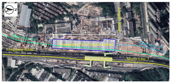
Figure 1.
Schematic plan of the Dayun Station.
The geological profile of the foundation pit was drawn based on the geological survey results, as shown in Figure 2. The types of strata change significantly from south to north, with the geological types sequentially comprising backfill soil, silty clay, blocky strongly weathered sandstone, soil-like strongly weathered sandstone, and moderately weathered sandstone. The foundation pit is primarily located in soft soil, which is characterized by susceptibility to liquefaction and deformation under construction disturbances [16,17,18].
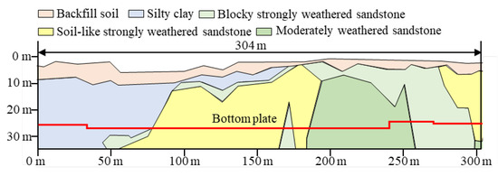
Figure 2.
Geological profile of the foundation pit.
2.2. Grouting Reinforcement Scheme
During foundation pit excavation, the area near the elevated station exhibits significant deformation [19]. Therefore, it was decided to implement grouting reinforcement between the elevated station and the foundation pit to enhance structural stability. Considering that this project is primarily located in soft soil, the jet grouting method was employed for ground reinforcement. This method uses high-pressure jets to cut through the soil and mix the grout with the soil, thereby forming cemented soil. Preliminary laboratory tests confirmed that the cement grout effectively enhances the strength of soft soil. Therefore, a cement grout with a cement-to-water ratio of 1:1 was selected as the grouting material.
Figure 3 shows the locations of the foundation pit and the foundation piles, as well as the grouting reinforcement area. In this project, the diaphragm wall is a reinforced concrete structure. The foundation piles of the elevated bridge are grouped in sets of six and connected as a whole through pile caps. The pile caps distribute the load from the elevated station and ensure coordinated settlement and deformation of piles. Considering the construction costs and the requirements for controlling the deformation of the foundation piles, two grouting schemes were planned: single-row grouting and double-row grouting. For the single-row grouting, the first row of grouting holes is located 0.8 m from the diaphragm wall, with a grouting hole diameter of 120 mm. The grouting depth extends from the pile cap to 3 m below the bottom of the foundation piles. This depth reaches the stable bedrock layer, ensuring sufficient reinforcement of the soft soil layer. For the double-row grouting, the second row of grouting holes is 0.8 m away from the first. The distance between adjacent grouting holes is 1.5 m to ensure the grout can fully diffuse within the soil and form a continuous reinforced zone.
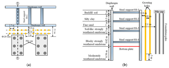
Figure 3.
Grouting reinforcement diagram. (a) Location of grouting holes. (b) Section ①-①.
2.3. Monitoring Plan
The stability of the retaining structure is crucial for the safe excavation of the foundation pit [20,21]. The inclinometers and electronic levels were used to monitor the horizontal displacement of the diaphragm wall and ground settlement, respectively. The location of monitoring points was shown in Figure 4. Inclinometers were embedded on the outside of the diaphragm wall (ZQT) to measure the horizontal displacement of the soil from the surface to a depth of 35 m. Seven ground settlement monitoring points (DBC) were installed on the surface. The spacing between the DBCs was shown in Figure 4. The monitoring system collects and records data once a day.
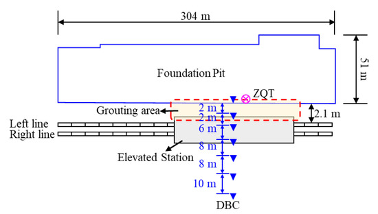
Figure 4.
Monitoring point locations.
3. Model Establishment
3.1. Introduction of the Numerical Simulation Model
A three-dimensional numerical simulation model for excavating the foundation pit was established by Plaxis 3D, as shown in Figure 5. The dimensions of the overall model are 564 × 397 × 80 m, and the strata were divided into six layers (Figure 5a). The distance between the model’s boundary and the excavation face was set to more than three times the maximum excavation depth to minimize the impact of boundary effects. For the boundary condition of the overall model, the normal displacement at the side surfaces, and the vertical displacement at the bottom surface was fixed, while the top surface of the model was a free boundary [22,23]. The foundation pit model was established based on the actual project dimensions, as shown in Figure 5b, with the pit measuring 304 × 77 × 26.7 m. The strata were meshed using tetrahedral elements, while one-dimensional beam elements were used to represent the internal steel supports and foundation piles.
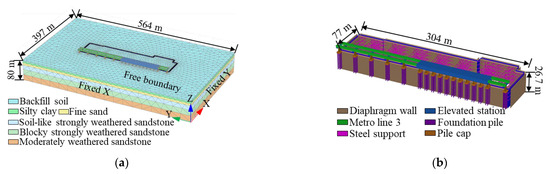
Figure 5.
3D numerical model. (a) Overall model. (b) Foundation pit structure.
In this study, considering that the foundation pit is primarily located in soft soil, the MCC model was selected to describe the mechanical characteristics of the soil. The Modified Cam-Clay (MCC) model is one of the most commonly used elastoplastic models, as it provides a straightforward and practical way to describe the stress–strain characteristics of soil. The MCC defines the stress–strain response of the soil using an elliptical yield surface and a symmetric stiffness matrix, with plastic strain as the hardening parameter, effectively capturing the soil’s compressibility and dilatancy [24]. The MCC model can also accurately reflect the creep behavior of soil and rock under dynamic loads [25,26]. The applicability of the MCC model in foundation pit engineering has been widely validated [27,28]. The mechanical parameters of the soils were shown in Table 1.

Table 1.
Mechanical parameters of soils.
The concrete structures, including the elevated station, pile caps, and diaphragm walls, were treated as ideal linear elastic materials. The bored piles in the retaining structure are converted into a homogeneous elastic diaphragm wall using the equivalent stiffness method. The equivalent thickness of the diaphragm wall was calculated by Equations (1) and (2). After grouting, the soil in the grouting area was considered as elastic material, with an elastic modulus of 150 MPa and a Poisson’s ratio of 0.32. The mechanical parameters of each component were shown in Table 2.
where is the diameter of the bored pile; is the distance between piles; is the equivalent thickness of the diaphragm wall.
Table 2.
Mechanical parameters of components.
3.2. Working Condition
The excavation process of the foundation pit was divided into eight steps:
- (1)
- Generate the initial geo-stress field. In this step, only the soil components are activated. The normal displacement at the side surfaces, and the vertical displacement at the bottom surface is fixed. Gravity loads are applied, and the initial stress of the soils is automatically assigned through static analysis;
- (2)
- Activate the elevated station and apply train load of 92.8 kPa on the railway track;
- (3)
- Activate the diaphragm wall and modify the soil parameters in the grouting area to elastic material;
- (4)
- Excavate the foundation pit to 2 m below the surface and install the first support (SS-1);
- (5)
- Excavate the foundation pit to 8.3 m below the surface and install the second support (SS-2);
- (6)
- Excavate the foundation pit to 15.3 m below the surface and install the third support (SS-3);
- (7)
- Excavate the foundation pit to 21.6 m below the surface and install the fourth support (SS-4);
- (8)
- Complete the final excavation of the foundation pit to the bottom (Bottom plate).
Three working conditions were designed: no grouting (Case-1), single-row grouting (Case-2), and double-row grouting (Case-3) to analyze the reinforcement effects of different grouting schemes.
3.3. Model Validation
The numerical simulation results and the monitored values were compared in Figure 6. The different colored curves in the figure represent the data at various excavation steps. The comparison between the numerical simulation data and the monitoring data of the diaphragm wall’s horizontal displacement shows a consistent trend across different stages of excavation (Figure 6a). The error between the simulation and the monitoring value is minimal, with a maximum deviation of only 2.64 mm. In comparing ground settlement, the numerically calculated settlement data are slightly smaller than the monitored values, with a maximum error of 2 mm, but the deformation patterns are consistent. The maximum settlement occurs 10 m away from the diaphragm wall. The error in the numerical simulation is attributed to factors such as surcharge loads, which were not considered in the simulation. The numerical simulation effectively reproduces the deformation trends observed during the foundation pit construction, and the simulation approach was considered reasonable.
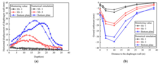
Figure 6.
Comparison between numerical simulation and monitoring data: (a) horizontal displacement of the diaphragm wall; (b) ground settlement.
4. Results Analysis
4.1. Analysis of the Foundation Pit
4.1.1. Displacement During the Construction Process
Figure 7 shows the horizontal displacement of the diaphragm wall at different excavation steps. It can be observed that the horizontal displacement of the diaphragm wall is positively correlated with the excavation depth, and the position of the maximum horizontal displacement shifts downward as the excavation progresses. Under the influence of the equivalent static load from the train, the horizontal displacement on the side near the elevated station is significantly larger than that on the opposite side.
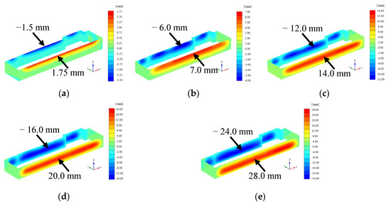
Figure 7.
Displacement of diaphragm wall at different excavation steps: (a) SS-1; (b) SS-2; (c) SS-3; (d) SS-4; (e) bottom plate.
Figure 8 shows the uplift curve of the foundation pit bottom along the width of the pit. It can be observed that the maximum uplift occurs at the center of the foundation pit, while the uplift at the edges of the pit is smaller. The curve is symmetrically distributed relative to the center of the pit. As the excavation progresses, the uplift at the bottom of the pit gradually increases, reaching a maximum value of 19.8 mm when the bottom plate is installed, while the uplift at the edges of the pit is 8.4 mm.
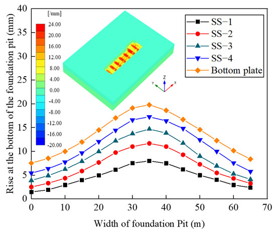
Figure 8.
Diaphragm wall displacement at different excavation stages.
4.1.2. Mechanical Response of the Diaphragm Wall
The horizontal displacement and bending moment of the diaphragm wall near the elevated station were shown in Figure 9. From the analysis of the horizontal displacement of the diaphragm wall (Figure 9a), it can be observed that the maximum displacement occurs at a depth of 16.6 m. Grouting reinforcement effectively reduces the horizontal displacement of the diaphragm wall. Compared to the no-grouting condition, the maximum horizontal displacement of the diaphragm wall in the single-row and double-row grouting conditions decreases by 17.8% and 22.3%, respectively. The analysis of the bending moment distribution of the diaphragm wall (Figure 9b) shows that the bending moment increases initially and then decreases, reversing at a depth of 22 m, indicating the influence of the diaphragm wall entering the bedrock. The maximum bending moment occurs at a depth of 17 m. Grouting reinforcement effectively reduces the bending moment of the diaphragm wall. Compared to the no-grouting condition, the maximum bending moment decreases by 14.9% and 18% for the single-row and double-row grouting conditions, respectively. Grouting reinforcement does not significantly change the diaphragm wall’s deformation mode or internal force distribution, primarily showing a numerical reduction. The reinforcement efficiency of the single-row grouting scheme is significantly higher than that of the double-row grouting scheme. Therefore, adopting the single-row grouting scheme is more economically efficient while meeting the requirement of deformation control.
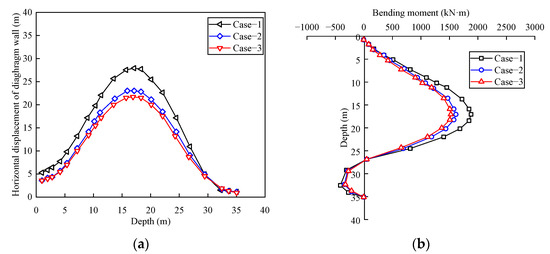
Figure 9.
Mechanical response of the diaphragm wall: (a) horizontal displacement; (b) bending moment.
4.1.3. Ground Settlement
The ground settlement curves were shown in Figure 10. After the foundation pit excavation, the maximum ground settlement without grouting was 30.3 mm. With the first-row grouting reinforcement scheme, the maximum ground settlement decreased to 20.8 mm, reducing by 9.5 mm or 31.4% compared to the no-grouting scheme. With the second-row grouting reinforcement, the maximum ground settlement further decreased to 18 mm, reducing by 12.3 mm or 40.5% compared to the no-grouting scheme. As the number of grouting rows increased, the rate of soil settlement gradually slowed, and the position corresponding to the maximum settlement remained unchanged. This shows that while the double-row grouting scheme provided the most effective control of ground settlement, the reinforcement efficiency of the single-row grouting scheme was still higher than that of the double-row grouting scheme.
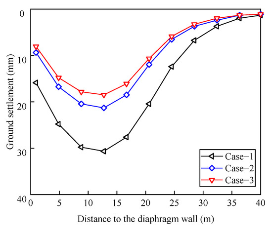
Figure 10.
Ground settlement curve.
4.2. Analysis of the Foundation Piles
4.2.1. Settlement of the Foundation Piles
Figure 11 shows the maximum settlement of each pile cap under different grouting schemes. Overall, the maximum settlement values of the pile caps were relatively scattered. The AT-11 cap had the highest settlement without grouting reinforcement, reaching 3.1 mm. After adopting the first-row grouting scheme, the settlement was reduced to 2.4 mm, a reduction of 0.7 mm or 22.6% compared to the no-grouting scheme. With the second-row grouting scheme, the settlement further decreased to 2.08 mm, a reduction of 1.02 mm or 32% compared to the no-grouting scheme. In general, the settlement deformation of the caps was significantly reduced after grouting reinforcement. The pile settlement curve gradually became smoother, and the uneven settlement between adjacent caps decreased with the increase in grouting rows, which is critical for ensuring the stable operation of the elevated lines.
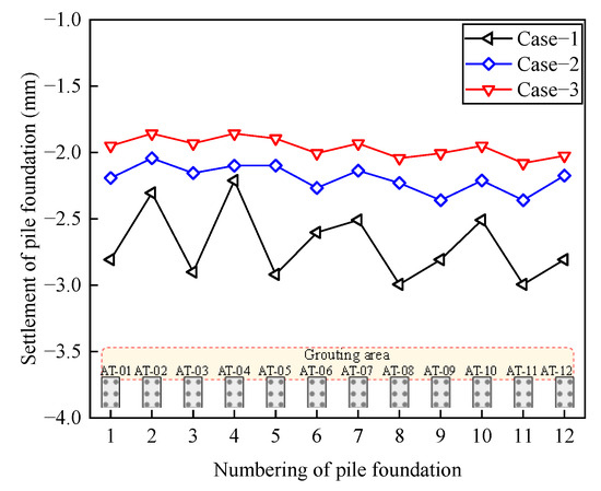
Figure 11.
Settlement curve of the elevated station.
4.2.2. Displacement and Bending Moment of Piles
The AT-08 pile was selected to analyze its horizontal displacement and bending moment under different grouting reinforcement schemes, as shown in Figure 12. The horizontal displacement of the pile increases first and then decreases along the length of the pile. After grouting reinforcement, the pile’s horizontal displacement and internal forces are significantly reduced, but the deformation mode and stress form remain unchanged, with the pile still bending towards the pit. The upper and lower parts of the pile exhibit negative bending moments, while the middle part exhibits positive bending moments. The position corresponding to the maximum horizontal displacement of the pile shifted upward after grouting, while the position of the maximum bending moment remained unchanged. Without grouting, the pile’s maximum horizontal displacement and bending moment were 7.4 mm and 1711.8 kN·m, respectively. After single-row grouting, the maximum horizontal displacement and bending moment were reduced to 4.1 mm and 1540.6 kN·m, a reduction of 45% and 10%, respectively. After double-row grouting, the maximum horizontal displacement and bending moment were further reduced to 3.8 mm and 1494.4 kN·m, a reduction of 48% and 12.7% compared to the no-grouting condition. Therefore, grouting reinforcement is more effective at controlling the deformation of the foundation piles than their internal forces, and the reinforcement efficiency of the single-row grouting scheme is significantly higher than that of the double-row grouting scheme.
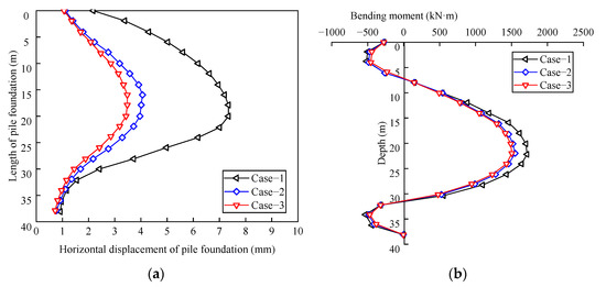
Figure 12.
Distribution of horizontal displacement and bending moment of the foundation pile: (a) horizontal displacement; (b) bending moment.
4.2.3. Bearing Capacity of the Foundation Pile
The axial force, pile-side friction, and load–settlement (Q-S) curve were selected to analyze the foundation pile’s bearing capacity. The Q-S curve represents the variation in the pile-top settlement as the pile-top load is incrementally increased during static load tests, serving as a comprehensive reflection of the load transfer in the pile-soil system and the resistance of the foundation pile [28]. Figure 13 illustrates the axial force, pile-side friction, and Q-S curve of the AT-08 piles under different grouting reinforcement schemes. It should be noted that the Q-S curve is obtained by applying incremental loads at the top of the AT-08 pile (Figure 13c). The dashed line in the figure indicates the load at the pile top when the maximum allowable settlement of 14 mm for the foundation pile in this project is reached.
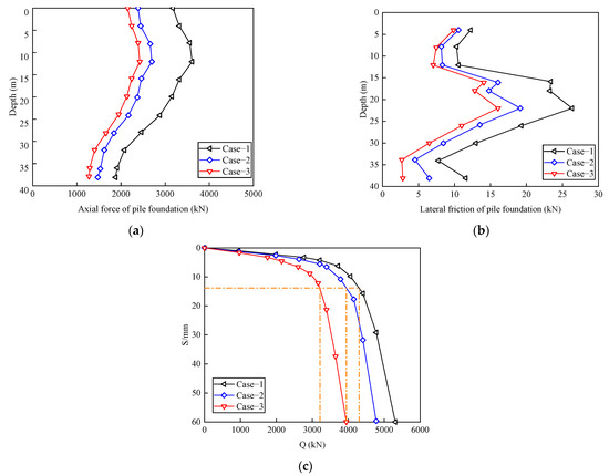
Figure 13.
Mechanical characteristics of the foundation pile: (a) axial force; (b) pile-side friction; (c) Q-S curve.
It can be observed that the axial force of the pile increases first and then decreases along the depth of the pile, gradually attenuating at a depth of 12 m. Due to the small axial force at the lower part of the pile, the relative displacement between the pile and the surrounding soil is minimal, making it difficult for the pile-side friction at the lower part of the pile to be fully mobilized. The pile-side friction at the bottom of the pile increases suddenly, mainly due to the higher stiffness of the soil at the pile tip. After applying vertical loads to the pile top, the Q-S curve of the pile top exhibits a ‘steep drop’ characteristic.
Grouting reinforcement has little effect on the deformation modes of the pile axial force, pile-side friction, and Q-S curve, but it does improve the bearing capacity of the foundation pile. Under the same pile-top load, the pile-top settlement is the largest in the no-reinforcement scheme, followed by the single-row grouting scheme, with the smallest settlement observed in the double-row grouting scheme. Without grouting reinforcement, the axial bearing capacity of the pile is 3154 kN. After single-row and double-row grouting reinforcement, the bearing capacity of the pile increases to 3900 kN and 4160 kN, representing increases of 23.7% and 31.9%, respectively. The bearing capacity of the double-row grouting scheme is 6.7% higher than that of the single-row grouting scheme, a relatively smaller increase compared to the 23.7% increase of the single-row grouting scheme. Overall, the double-row grouting scheme provides the best results.
5. Discussion and Limitation
5.1. Discussion
This study validated the effectiveness of the grouting scheme in controlling the deformation and settlement of foundation pits located near elevated structures. However, the applicability of the grouting techniques under varying geotechnical and engineering conditions requires further discussion.
The double-row grouting scheme offers enhanced effectiveness due to the larger grout injected into the soil, leading to more thorough stabilization. This method creates two layers of reinforcement, which overlap and provide a more uniform distribution of pressure, significantly improving the soil’s bearing capacity and reducing settlement and lateral displacement. While the double-row grouting scheme offers superior technical performance, it involves higher material costs, more complex execution, and a longer construction time than single-row grouting. The increased grout, additional drilling, and the need for more detailed monitoring and quality control increase the overall cost. While slightly less effective in terms of deformation control, the single-row grouting scheme provides a more cost-efficient solution with reduced material and labor costs. This method is more accessible to implement and requires less time, making it ideal for projects with less complex engineering demands.
Additionally, adjustments to the grout composition and injection patterns may be necessary for sites experiencing complex loading conditions—such as dynamic loads from railways or seismic impacts. For example, the interaction between grouting layers and soil behavior under seismic conditions could affect long-term stability. Future studies could explore using specialized grout materials designed to withstand cyclic loading.
Thus, the findings of this research are most applicable to projects in soft, highly permeable soils with moderate structural loads. However, when applied to denser soils or locations with more challenging geotechnical conditions, additional adjustments to the grouting methodology may be required to maintain effectiveness. Further field studies would help validate these insights and expand understanding of the grouting scheme’s adaptability across various construction environments.
5.2. Limitation
Specific components, such as foundation piles and diaphragm walls, were treated as ideal linear elastic elements to ensure computational efficiency. These simplifications may not fully capture the complex interactions between soil and structures, especially under non-linear stress conditions. The soil layers in the model were considered homogeneous with pre-determined mechanical properties. In reality, soil conditions can vary significantly across small areas, which might affect the accuracy of the predicted deformations and internal forces.
Although the numerical simulation was simplified in this study, the comparison between the simulation results and monitoring data verified the validity of the simulation. Therefore, the impact of these simplifications on the simulation results is considered acceptable.
6. Conclusions
This study investigates the influence of grouting reinforcement on the stability and deformation characteristics of foundation pits adjacent to elevated railways. The research evaluates single-row and double-row grouting reinforcement schemes through full-scale numerical simulations. The key findings can be summarized as follows:
Grouting reinforcement significantly enhances the stability of the diaphragm wall and reduces surface settlement. In the single-row and double-row grouting scenarios, the maximum horizontal displacement of the diaphragm wall was reduced by 17.8% and 22.3%, respectively, compared to the non-grouted case. Furthermore, surface settlement decreased by 31.4% with single-row grouting and 40.5% with double-row grouting. These reductions demonstrate that grouting effectively mitigates ground deformation induced by foundation pit excavation;
The grouting reinforcement also improved the mechanical response of the elevated bridge foundation piles. Without reinforcement, the pile’s maximum horizontal displacement and bending moment were 7.4 mm and 1711.8 kN·m, respectively. Single-row grouting reduced these values by 45% and 10%, while double-row grouting decreased them by 48% and 12.7%. The maximum displacement position shifted upward after grouting, indicating a beneficial redistribution of structural loads;
While both grouting schemes improved structural performance, the single-row grouting approach offered a better balance of reinforcement efficiency and economic feasibility. It effectively controlled deformation and maintained structural safety while meeting engineering requirements. Consequently, single-row grouting is recommended for similar projects due to its cost-efficiency and practicality.
While the study demonstrated effective grouting reinforcement in soft soils, future research could explore its application in other soil types, such as clay or silty sand. The performance of grouting techniques may vary significantly in less permeable soils or under mixed strata conditions. Comparative studies involving multiple soil types would help generalize the findings and establish guidelines for diverse geotechnical conditions. The conclusions of this study have broader implications for construction projects adjacent to sensitive urban infrastructure, such as metro tunnels or historical buildings. Future work could extend these insights by applying the grouting techniques in similar high-risk construction environments, further validating the effectiveness of the proposed schemes.
Author Contributions
Conceptualization, G.Z., X.W., X.L., L.C. and Y.L. (Yongjie Li); methodology, G.Z., X.W., X.L., L.C. and Y.L. (Yongjie Li); software, G.Z., X.W., X.L., L.C.; Y.L. (Yongjie Li), C.L., R.W. and Y.L. (Yingpeng Li); validation, G.Z., C.L. and Y.L. (Yongjie Li); formal analysis, X.L. and L.C.; investigation, Y.L. (Yongjie Li); resources, X.L.; data curation, G.Z. and X.W.; writing—original draft preparation, G.Z. and R.W.; writing—review and editing, G.Z., X.W., Y.L. (Yongjie Li), X.L. and L.C.; visualization, C.L. and R.W.; supervision, L.C. and Y.L. (Yingpeng Li); project administration, X.L.; funding acquisition L.C. All authors have read and agreed to the published version of the manuscript.
Funding
This research was funded by the National Natural Science Foundation of China, grant number No. 52379104 & 52090084, the Technical Innovation Foundation of Shenzhen, grant number No. 20231121224122001.
Institutional Review Board Statement
Not applicable.
Informed Consent Statement
Not applicable.
Data Availability Statement
Data are contained within the article.
Conflicts of Interest
Author Xuhui Li and Yongjie Li were involved as a consultants in Shenzhen Raw Water Co., Ltd.; Author Le Chang worked as a senior engineer in Sinohydro Bureau 14 Co., Ltd.
References
- Liu, J.; Chau, K.W.; Bao, Z. Multiscale spatial analysis of metro usage and its determinants for sustainable urban development in Shenzhen, China. Tunn. Undergr. Space. Technol. 2023, 133, 104912. [Google Scholar] [CrossRef]
- Zhong, W.; Wan, Q.; Nie, N.; Ding, H.; Gao, F.; Xu, C. Research on the optimal design of retaining piles of a wide metro tunnel foundation pit based on deformation control. Buildings 2024, 14, 1906. [Google Scholar] [CrossRef]
- Wu, W.; Lu, H.; Chen, S.; Zhang, D. Effect and control of foundation pit excavation on existing tunnels: A state-of-the-art review. Tunn. Undergr. Space. Technol. 2024, 147, 105704. [Google Scholar]
- Liu, Z.; Fang, Q.; Shen, Y.; Ai, Q.; Wang, H.; Huang, X.; Yuan, Y. Two-stage surrogate modeling strategy for predicting foundation pit excavation-induced strata and tunnel deformation. Tunn. Undergr. Space. Technol. 2024, 151, 105845. [Google Scholar] [CrossRef]
- Zhao, Y.; Chen, X.; Hu, B.; Huang, L.; Lu, G.; Yao, H. Automatic monitoring and control of excavation disturbance of an ultra-deep foundation pit extremely adjacent to metro tunnels. Tunn. Undergr. Space. Technol. 2023, 142, 105445. [Google Scholar] [CrossRef]
- Wu, J.; Yu, J.; Fang, F.; Lin, G.; Tang, X.; Ding, H.; Xu, C. Impact of Excavation on Adjacent Elevated Bridges and Optimization Analysis of Deformation Control. Buildings 2024, 14, 3197. [Google Scholar] [CrossRef]
- Zeng, C.F.; Powrie, W.; Chen, H.B.; Wang, S.; Diao, Y.; Xue, X.L. Ground behavior due to dewatering inside a foundation pit considering the barrier effect of preexisting building piles on aquifer flow. J. Geotech. Geoenviron. Eng. 2024, 150, 05024004. [Google Scholar] [CrossRef]
- Ye, S.; Zhao, Z.; Wang, D. Deformation analysis and safety assessment of existing metro tunnels affected by excavation of a foundation pit. Undergr. Space. 2021, 6, 421–431. [Google Scholar] [CrossRef]
- Cheng, X.; Zhao, L.; Han, S.; Ji, Y.; Xu, Z.; Meng, L.; Pan, J.; Zheng, G.; Wang, R. In-situ test and calculation method for horizontal deformation of soil induced by multi-row grouting. Can. Geotech. J. 2023, 61, 1723–1937. [Google Scholar] [CrossRef]
- Zheng, J.; Shen, M.; Tu, S.; Chen, Z.; Ni, X. Investigations of countermeasures used to mitigate tunnel deformations due to adjacent basement excavation in soft clays. Geomech. Eng. 2024, 36, 563. [Google Scholar]
- Shan, Y.; Luo, J.; Wang, B.; Zhou, S.; Zhang, B. Critical application zone of the jet grouting piles in the vicinity of existing high-speed railway bridge in deep soft soils with medium sensibility. Soils. Found. 2024, 64, 101407. [Google Scholar] [CrossRef]
- Fu, Y.; Wang, B.; Wu, H.; Chen, X.; Sun, X.; Bian, Y.; Shen, X. Theoretical analysis on horizontal rectification of tunnel near deep foundation pit by grouting. Tunn. Undergr. Space. Technol. 2023, 133, 104977. [Google Scholar] [CrossRef]
- Zheng, Z.; Liu, R.; Li, S.; Zhang, Q. Numerical modeling and verification of grouting with mold bag treatment on seepage failure in foundation excavation. Geomat. Nat. Haz. Risk. 2018, 9, 1172–1185. [Google Scholar] [CrossRef]
- Xue, H. Research on the control of excavation deformation of super deep foundation pit adjacent to the existing old masonry structure building. Sustainability 2023, 15, 7697. [Google Scholar] [CrossRef]
- Xiao, Z.; Xie, S.; Hu, A.; Chen, Y.; Wang, M. Displacement control in irregular deep excavation adjacent to tunnel groups in structural soil: A case study of MJS cement-soil composite piles and grouting rectification. Case. Stud. Constr. Mat. 2024, 20, 03085. [Google Scholar] [CrossRef]
- Bao, X.; Yuan, H.; Shen, J.; Liu, C.; Chen, X.; Cui, H. Numerical analysis of seismic response of a circular tunnel-rectangular underpass system in liquefiable soil. Comput. Geotech. 2024, 174, 106642. [Google Scholar] [CrossRef]
- Bao, X.; Bao, Z.; Shen, J.; Chen, X.; Cui, H. An optimization DEM modelling method for soil-fibre undrained cyclic loading tests model based on the influence range of fibre. Comput. Geotech. 2025, 177, 106846. [Google Scholar] [CrossRef]
- Bao, X.; Li, J.; Shen, J.; Chen, X.; Zhang, C.; Cui, H. Comprehensive multivariate joint distribution model for marine soft soil based on the vine copula. Comput. Geotech. 2025, 177, 106814. [Google Scholar] [CrossRef]
- You, X.; Zhou, Q.; Xiao, Y.; Tong, L.; Yang, Q. Numerical Study on the Coupling Effect on a Retaining Structure of a Complex Deep Foundation Pit Group Excavation in a Soft-Soil Area. Appl. Sci. 2023, 13, 3263. [Google Scholar] [CrossRef]
- Ge, C.; Yang, M.; Li, P.; Zhang, M.; Zhang, Z. Performance and environmental impacts of deep foundation excavation in soft soils: A field and modeling-based case study in Nanjing, China. Undergr. Sp. 2024, 18, 218–238. [Google Scholar] [CrossRef]
- Zhang, J.; Xie, R.; Zhang, H. Mechanical response analysis of the buried pipeline due to adjacent foundation pit excavation. Tunn. Undergr. Space. Technol. 2018, 78, 135–145. [Google Scholar] [CrossRef]
- Gao, X.; Tian, W.P.; Zhang, Z. Analysis of deformation characteristics of foundation-pit excavation and circular wall. Sustainability. 2020, 12, 3164. [Google Scholar] [CrossRef]
- Lin, Q.; Zhang, Y.; Yang, C.; Wang, X.; Lei, T.; Ju, C.; Yao, Z.; Yao, K. Evaluation of differential settlement of subgrade for highway-widening projects. Sustainability 2023, 15, 2950. [Google Scholar] [CrossRef]
- Zou, Q.; Chen, C.; Chen, Z.; Peng, K.; Lv, H.; Zhan, J. Characterization and differences of acoustic signals response of semi-circular red sandstone under combined monotonous and cyclic loadings. Geomech. Geophys. Geo. 2024, 10, 146. [Google Scholar] [CrossRef]
- Zou, Q.; Chen, Z.; Zhan, J.; Chen, C.; Gao, S.; Kong, F.; Xia, X. Morphological evolution and flow conduction characteristics of fracture channels in fractured sandstone under cyclic loading and unloading. Int. J. Min. Sci. Technol. 2023, 33, 1527–1540. [Google Scholar] [CrossRef]
- Li, Z.; Zhao, G.F.; Wei, X.; Deng, X. Numerical modelling of multiple excavations in an ultra-deep foundation using an enhanced distinct lattice spring model with modified cam clay model. Tunn. Undergr. Space. Technol. 2024, 152, 105875. [Google Scholar] [CrossRef]
- Bao, X.; Cheng, Z.; Lv, C.; Shen, J.; Chen, X.; Cui, H. Analysis of the influence of deep foundation excavation on adjacent viaduct pile foundation considering train dynamic loads. Appl. Sci. 2023, 13, 1572. [Google Scholar] [CrossRef]
- Zhao, X.; Yan, N.; Bai, X.; Sang, S.; Chen, X.; Zhang, Y.; Zhang, M. Vertical compressive bearing performance and optimization design method of large-diameter manually-excavated rock-socketed cast-in-place piles. Sci. Rep. 2023, 13, 14234. [Google Scholar] [CrossRef]
Disclaimer/Publisher’s Note: The statements, opinions and data contained in all publications are solely those of the individual author(s) and contributor(s) and not of MDPI and/or the editor(s). MDPI and/or the editor(s) disclaim responsibility for any injury to people or property resulting from any ideas, methods, instructions or products referred to in the content. |
© 2024 by the authors. Licensee MDPI, Basel, Switzerland. This article is an open access article distributed under the terms and conditions of the Creative Commons Attribution (CC BY) license (https://creativecommons.org/licenses/by/4.0/).