1. Introduction
Footings are placed adjacent to one another to efficiently transfer the loads downward. As a result, the overlapped impacts in soils caused by neighboring footings cannot simply be neglected. Stuart [
1] was the first to propose an efficiency factor that can be used to describe the interfering impact of two neighboring strip footings in sand. The factor was defined as the ratio of the ultimate bearing capacity of two neighboring footings to a single specific footing. Although highlighting the importance of the footing settlement pattern, Das and Larbi-Cherif [
2] carried out laboratory model tests to investigate the efficiency factor of the same problem as Stuart [
1]. They found that the experimental results of the efficiency factors were in good agreement with those predicted by the theory. Upper-bound techniques and stress characteristics were employed by Kumar and Ghosh [
3,
4] to analytically derive the efficiency factors of two adjacent strip footings on cohesionless soil, where all possible values of the internal friction angle of sand as well as the full range of the distance between two footings were considered. Kumar and Ghosh [
3,
4] proposed two mechanisms of two footings at the failure, which were validated using the previous results [
1,
2]. The authors also prepared a wide range of parametric results based on their study.
The numerical technique of lower-bound finite-element limit analysis (FELA) was used by Kumar and Kouzer [
5] to compute the solutions of the efficiency factors of twin neighboring strip footings on unconsolidated soil. Note that Kumar and Kouzer [
5] were the first to use lower-bound finite-element limit analysis to compute the efficiency factors of two strip footings. Considering the effect of surcharge loading, the efficiency factors of two footings on cohesive–frictional soils were reported by Mabrouki et al. [
6] using finite difference method software with explicit numerical formulations, namely Fast Lagrangian Analysis of Continua (FLAC). The results from Mabrouki et al. [
6] demonstrated a tendency of the efficiency factors that was similar to those observed in [
3,
4,
5], and a couple of design charts were provided. Further, Pal et al. [
7] and Lavasan et al. [
8] also investigated the bearing capability of two nearby bordered strip footings in sand. Graham et al. [
9] assessed the interfering impact of three tightly spaced strip footings in sand utilizing the characteristic techniques and small-scale model testing. Moreover, by applying upper-bound (UB) and lower-bound (LB) finite-element limit analysis (FELA), Kouzer and Kumar [
10], Kumar and Bhattacharya [
11], and Yang et al. [
12] studied the effectiveness factors of numerous evenly spaced strip footings in cohesionless soils. Recently, Ghazavi and Dehkordi [
13] provided a comprehensive assessment of the interference impact on the performance of shallow strip footings.
According to Terzaghi’s bearing capacity equation, the three bearing capacity factors consist of the cohesion factor (
Nc), the surcharge factor (
Nq), and the unit weight factor (
Nγ). In all published studies, only Mabrouki et al. [
6] proposed the efficiency factors of two footings by considering all impacts of soil cohesion, surcharge loading, and unit weight. Their solutions were limited to
ϕ = 20° to 40°. Note that, in the past, there was no work that employed a finite-element limit analysis with an adaptive mesh refinement to compute rigorous bound solutions. The application of the adaptive mesh refinement can provide more accurate solutions from both upper- and lower-bound methods. The present charts of the efficiency factors can be used for practical engineers who have to deal with footing problems. In this study, we aimed to determine the efficiency factors of two unique interference situations: two tightly spaced strip footings and numerous tightly spaced strip footings. The present study considered the full range of
ϕ = 5° to 45°, and the efficiency factors were quantitatively studied using a robust upper-bound (UB) and lower-bound (LB) finite-element limit analysis (FELA). It aimed to provide comprehensive results for design practices using rigorous upper- and lower-bound solutions.
2. Problem Statement and FELA
Currently, finite-element limit analysis (FELA) has become a powerful approach for analyzing many bearing capacity problems in civil engineering. It is a technique that combines the powerful capabilities of finite-element discretization in order to handle the complexity of the geotechnical problems that include the boundary conditions and loading as well as the complicated soil stratifications. FELA employs the plastic bound theorem, which can provide upper-bound (UB) and lower-bound (LB) solutions. Note that the upper-bound solutions are always larger than the true solutions whereas the lower-bound solutions are always lower than the true solutions. By improving these upper- and lower-bound approaches, the gap between them becomes smaller, which mean the values of the upper- and lower-bound solutions become closer. At some point, when both the lower and upper-bound solutions become the same, it would mean the true solutions could be obtained. The lower- and upper-bound theorem also requires the assumption of a rigid, perfectly plastic material with an associated flow rule [
14,
15,
16,
17].
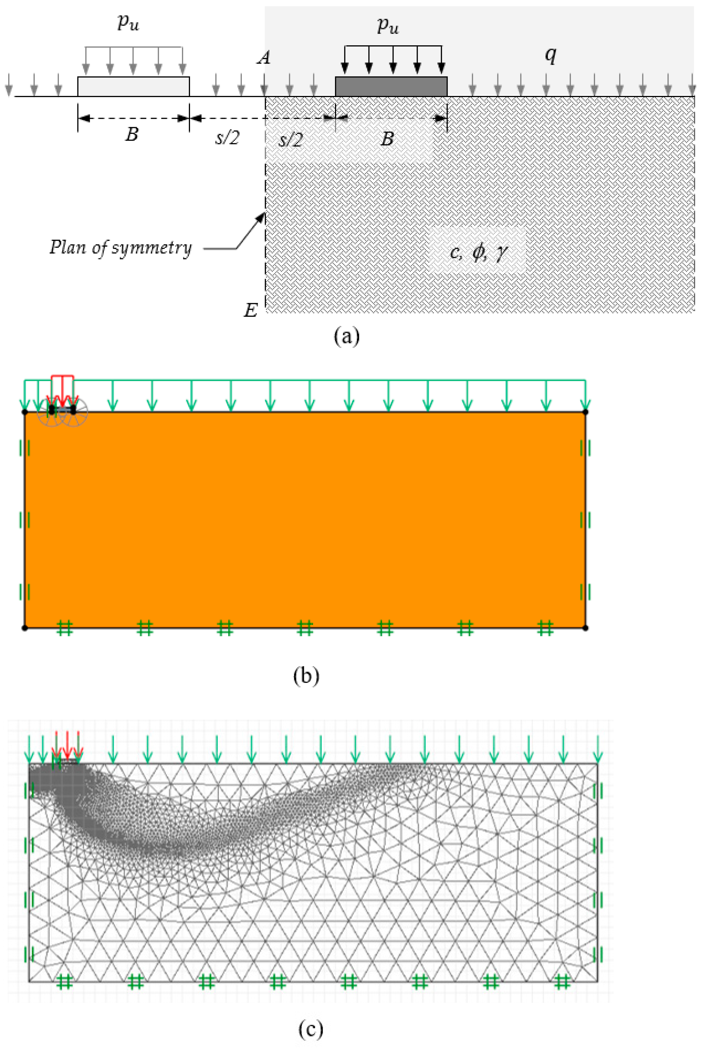
The first problem considered here was for two interfering footings. Each footing had the same width (B) and was subjected to a limit vertical pressure of
pu (i.e., the bearing capacity of the footing). As shown in
Figure 1a, the edge-to-edge distance of the two interfering footings was defined as
s. The surcharge pressure was denoted by
q. The line of symmetry in the middle of the domain was indicated by a dashed line (AE). Owing to the problem’s symmetry, the simulation utilized just half of the domain, and the symmetrical boundary condition (the left boundary) only required the nodes to move vertically (
Figure 1b). At the right boundary (or the far side), the same condition was applied. The bottom border was restricted with no movement allowed in both directions, while the upper boundary was unrestricted.
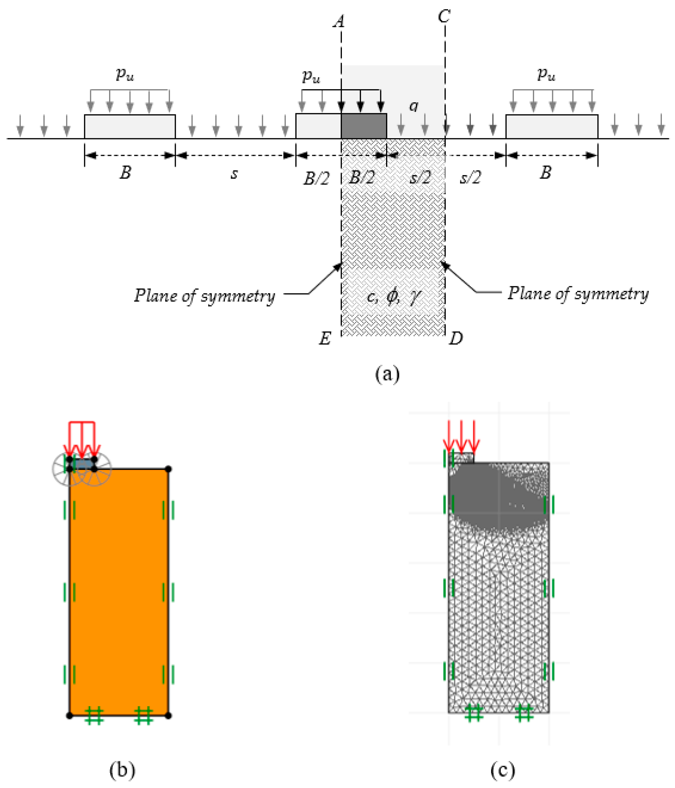
The second problem was for multiple interfering footings. Each footing had the same width (B) and a limit vertical pressure of
pu applied at each footing, as shown in
Figure 2a. The edge-to-edge footing distance was defined as s, and the surcharge pressure was denoted by q. It is interesting to note that the symmetrical planes were represented by the dashed lines CD and AE, which represented the problem’s domain, as seen in
Figure 2b. The same as with two interfering footings, the boundary condition for the two symmetric planes only required the nodes to be fixed in the horizontal direction. The rest of the boundary conditions were identical compared to the case of two overlapping footings.
Sloan [
14,
15] established the first studies of linear programming, known as FELA. Lyamin and Sloan [
16,
17] and Krabbenhoft et al. [
18] further expanded the approach to a nonlinear programming framework. The fundamental bound theorems are based on a rigid, perfectly plastic material and have been successfully applied in various ways to solve for stability solutions in the geotechnical fields [
19,
20,
21,
22,
23,
24,
25,
26,
27,
28].
A finite-element lower-bound analysis employs three-node triangular components. The nodal stresses are specified to be the primary unknown variables in each triangle element. For creating the continuity of normal and shear stresses, as well as the interfaces of all the elements, statically allowable stress discontinuities are permitted. In a typical LB analysis, the stress equilibrium requirements, the stress boundary condition, and the Mohr–Coulomb failure criterion are all restrictive, with the propose of maximizing the collapse loads of problems. The upper-bound theorem necessitates a kinematically acceptable velocity field with external work larger than or equal to plastic shear dissipation. Six-node triangular components are employed in the UB method’s formulation. The horizontal (u) and vertical (v) velocities are specified as the fundamental unknown at each node of the element. These two theorems are excellently suited for second-order cone programming nonlinear programming optimization problems (SOCP). The constraints employed in this approach are nonlinear and non-smooth, but they are nonetheless convex and analyzed. More details of the numerical formulation can be found in Sloan [
29] and OptumG2 [
30]. It should also be noted that a bearing capacity analysis using a finite-element limit analysis (FELA) is basically based on the limit analysis theory. As a result, this FELA requires only the strength parameters of soils (cohesion and friction angle). The parameters of stiffness, such as Poisson’s ratio and Young’s modulus, are not required in FELA. Consequently, the deformations of the problems cannot be obtained, which is different from the conventional displacement-based finite-element method [
14,
15,
16,
17].
In the FELA of OptumG2, the underlying soil was modeled with volume elements using a Mohr–Coulomb material. The concrete footings were modeled using rigid volume elements. The contact interface between footings and soils was considered to be perfectly rough in this study. It was noted that neglectable differences were reported between smooth and rough interfaces for the bearing capacity problem of flat ground. The adaptive mesh refinement approach proposed by Ciria et al. [
31] was employed. In all investigations, five adaptive stages were used, with the first phase containing 5000 elements and the last phase containing about 10,000 elements (or the fifth step). The final adaptive meshes for the problems of two and multiple interfering footings are shown in
Figure 1c and
Figure 2c, respectively.
3. The Efficiency Factor
The superposition equation proposed by Terzaghi [
32] is often used to determine the bearing capacity (
pu) of a single strip footing in cohesive–frictional soil, with the surcharge loading as expressed in Equation (1):
where the soil cohesion is
c, the soil unit weight is
γ, and the surcharge loading is represented by
q.
B denotes as the width of the footing, and
Nc,
Nq, and
Nγ are the bearing capacity factors for a single strip footing. Note that the bearing capacity factors are influenced by the soil’s internal friction angle (
ϕ) and they are obtained from a finite-element limit analysis of a single strip footing. Equation (2) shows the process involved in calculating the respective bearing capacity factors (
Figure 3).
For the bearing capacities of two interfering footings and multiple interfering footings (
pu,m), Terzaghi’s bearing capacity equation can be modified to Equation (3):
where the three efficiency factors are denoted by
ξc,
ξq, and
ξγ. These factors are literally the ratios of the ultimate bearing capacity of two interfering footings or multiple interfering footings (
pu,m) to the ultimate bearing capacity of a single isolated footing (
pu). The procedure for determining each efficiency factor individually is expressed in Equations (4a–c)
The efficiency factors are functions of the soil’s internal friction angle (
ϕ) and the spacing ratio (
s/B), as expressed in Equation (5).
The impacts of the spacing ratio (s/B) and the soil’s internal friction angle (ϕ) on the efficiency factors of interfering strip footings are explored and reported in the form of a design chart. The proposed efficiency factors can be conveniently used to estimate the bearing capacity using the modified equation (Equation (3)).
4. Two Interfering Footings
The numerical results of the three efficiency factors
ξc,
ξq, and
ξγ are shown in
Figure 4,
Figure 5 and
Figure 6 against the distance ratio (
s/B). They are for the different values of the internal friction angle (
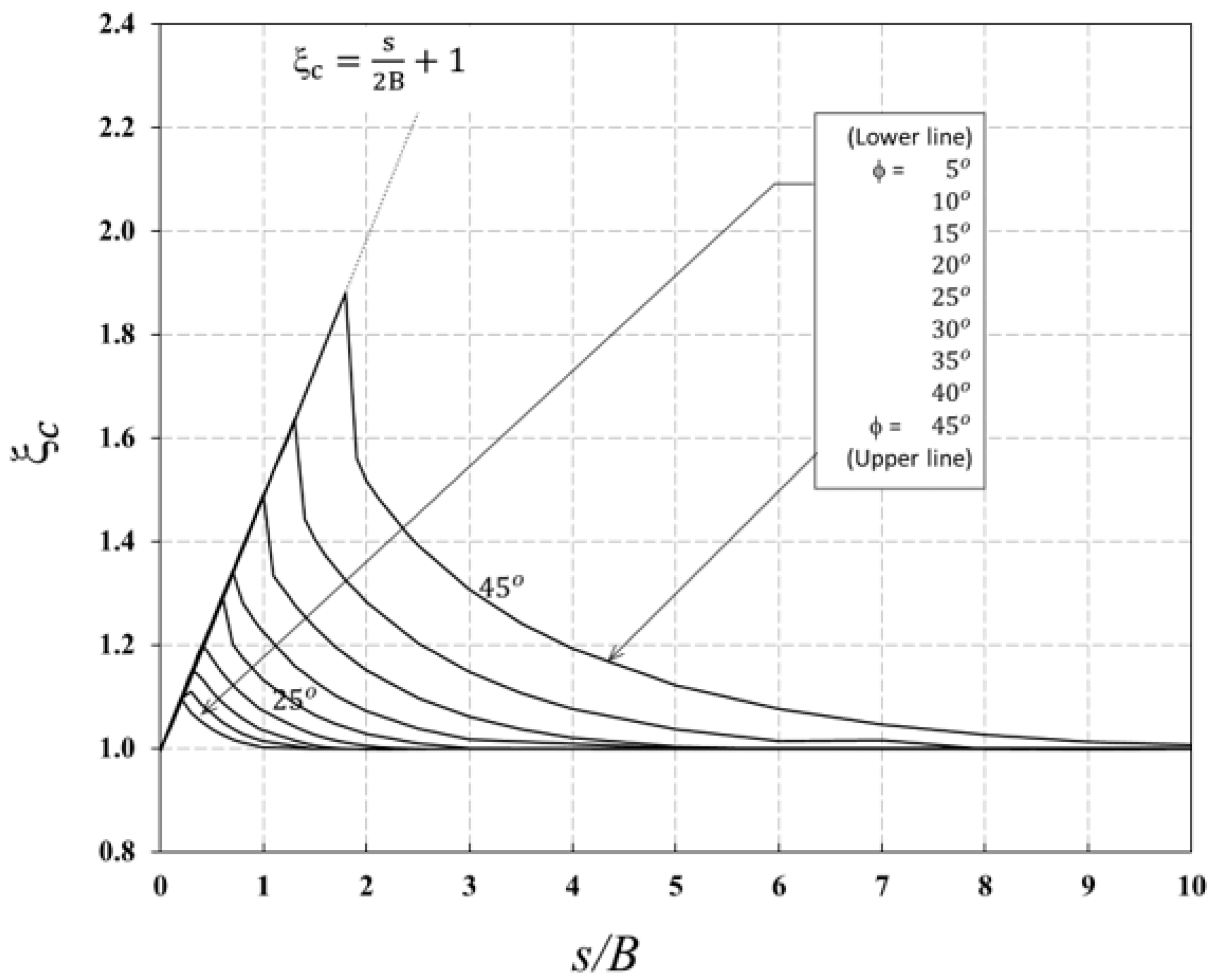
ϕ = 5° to 45°). In
Figure 4, the cohesion efficiency factor began at
ξc = 1 at
s/B = 0 (i.e., a single footing), and it increased linearly, with a small increase in
s/B. This occurred at any value of
ϕ, and the relationship between
ξc and
s/B may be written as a linear equation (
ξc = (
s/2B) + 1). Depending on the internal soil friction angle (
ϕ), at some points after reaching the peak, the cohesion efficiency factor
ξc decreased sharply as the distance ratio (
s/B) further increased, and it eventually returned to unity (
ξc = 1) at various
s/B values. It is to be noted that
ξc = 1 is the efficiency factor of a single footing or two footings that are placed far away from each other.
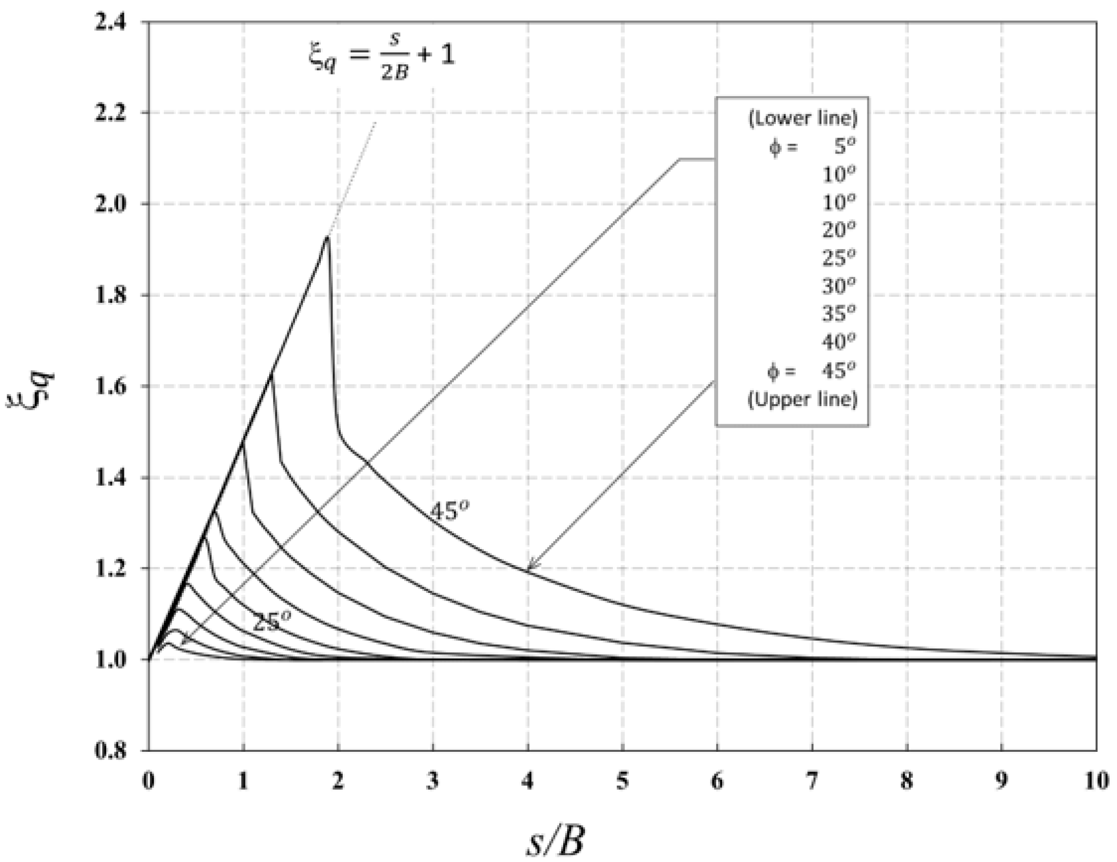
Interestingly, the numerical results of the surcharge efficiency factor
ξq in
Figure 5 showed the same results as in those of
ξc. The linear equation was also found to be
ξq = (
s/2B) + 1. A similar observation was also reported by Lavasan et al. [
8]. In general, the larger the internal friction angle (
ϕ), the greater the values of the efficiency factors.
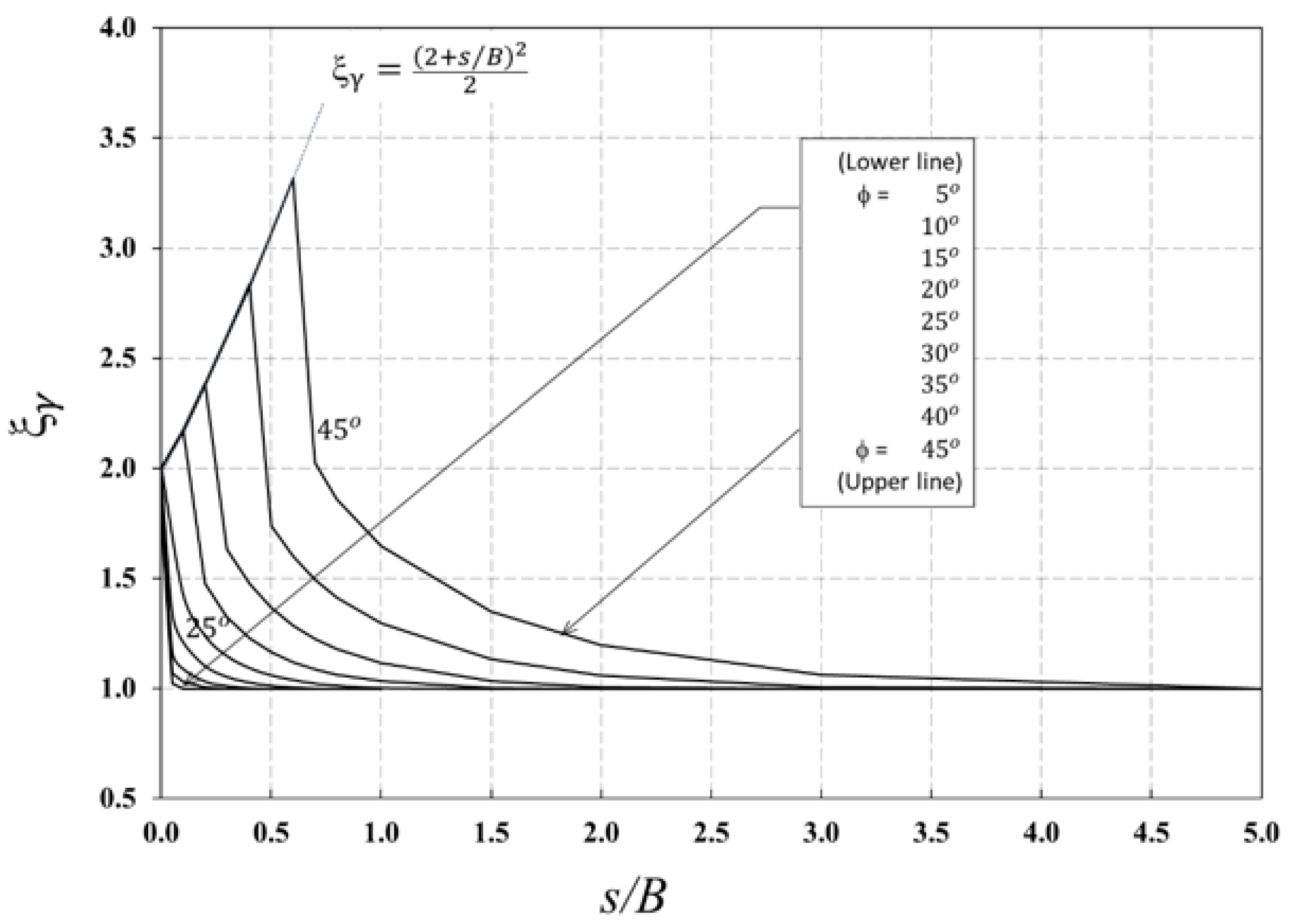
Figure 6 shows that the unit weight efficiency factor
ξγ started at
ξγ = 2 at
s/B = 0 (i.e., a single footing), and it increased nonlinearly, with a small increase in
s/B. This occurred for all values of
ϕ, and the relationship between
ξc and
s/B can be expressed by the equation
ξγ = (2 +
s/B)
2/2. After reaching a peak at a certain respective
s/B, also depending on the value of
ϕ, the unit weight efficiency factor
ξγ decreased dramatically and eventually returned to unity at various
s/B values. The overall trend was very similar to
ξc, as discussed above.
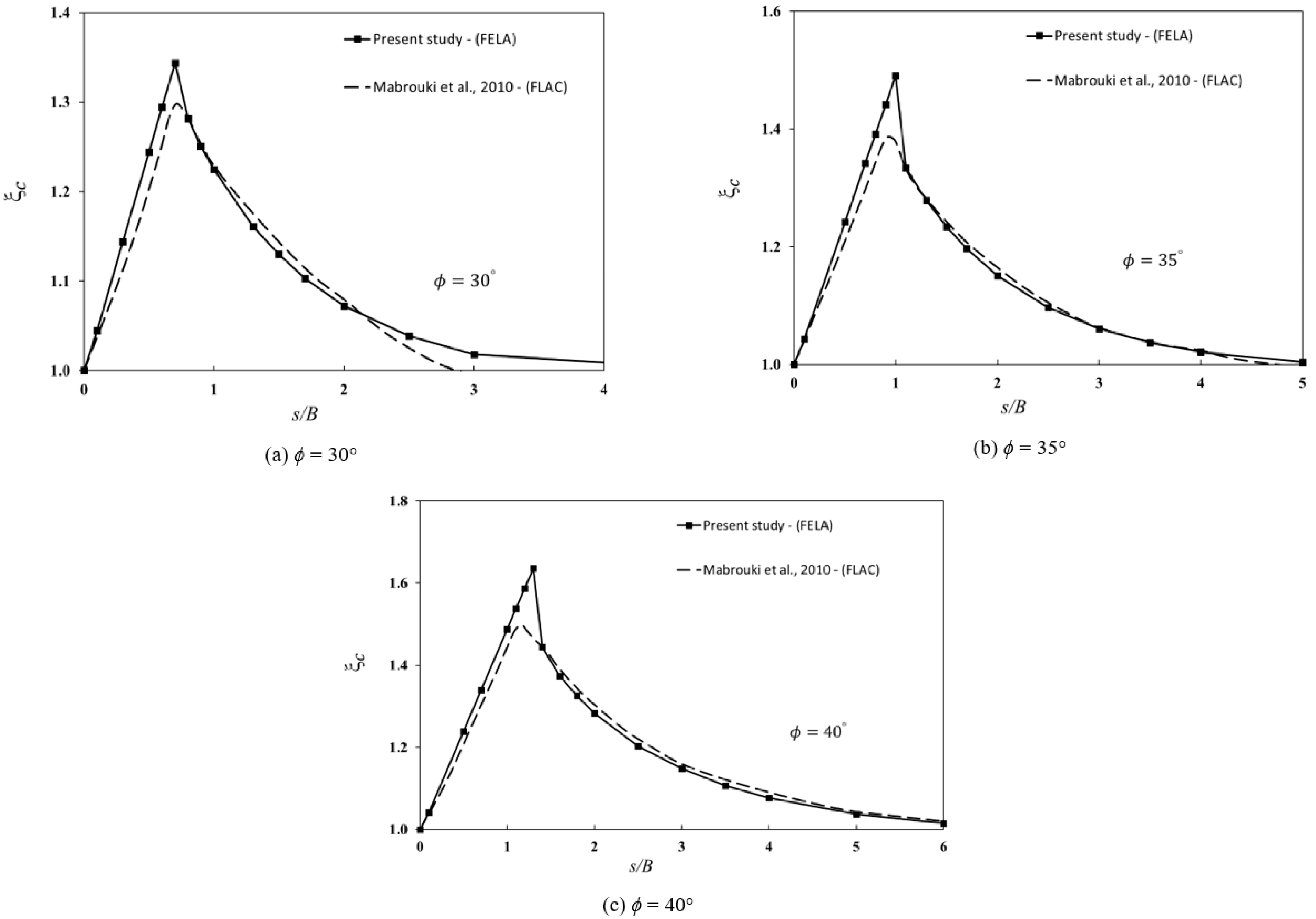
Figure 7a–c show the comparisons of
ξc for the different values of
ϕ = 30°, 35°, and 40°. In general, the finite difference results (FDM) presented by Mabroukei et al. [
6] are in good agreement with the present FELA results. It is interesting to note that those produced by FDM could not reach the peak values of the current FELA. This resulted in some differences, as shown in
Figure 7a–c.
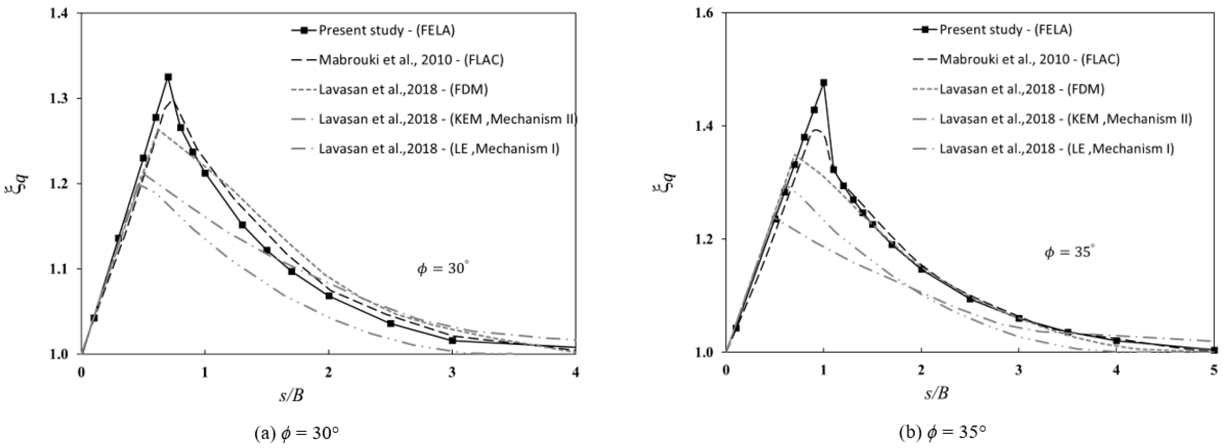
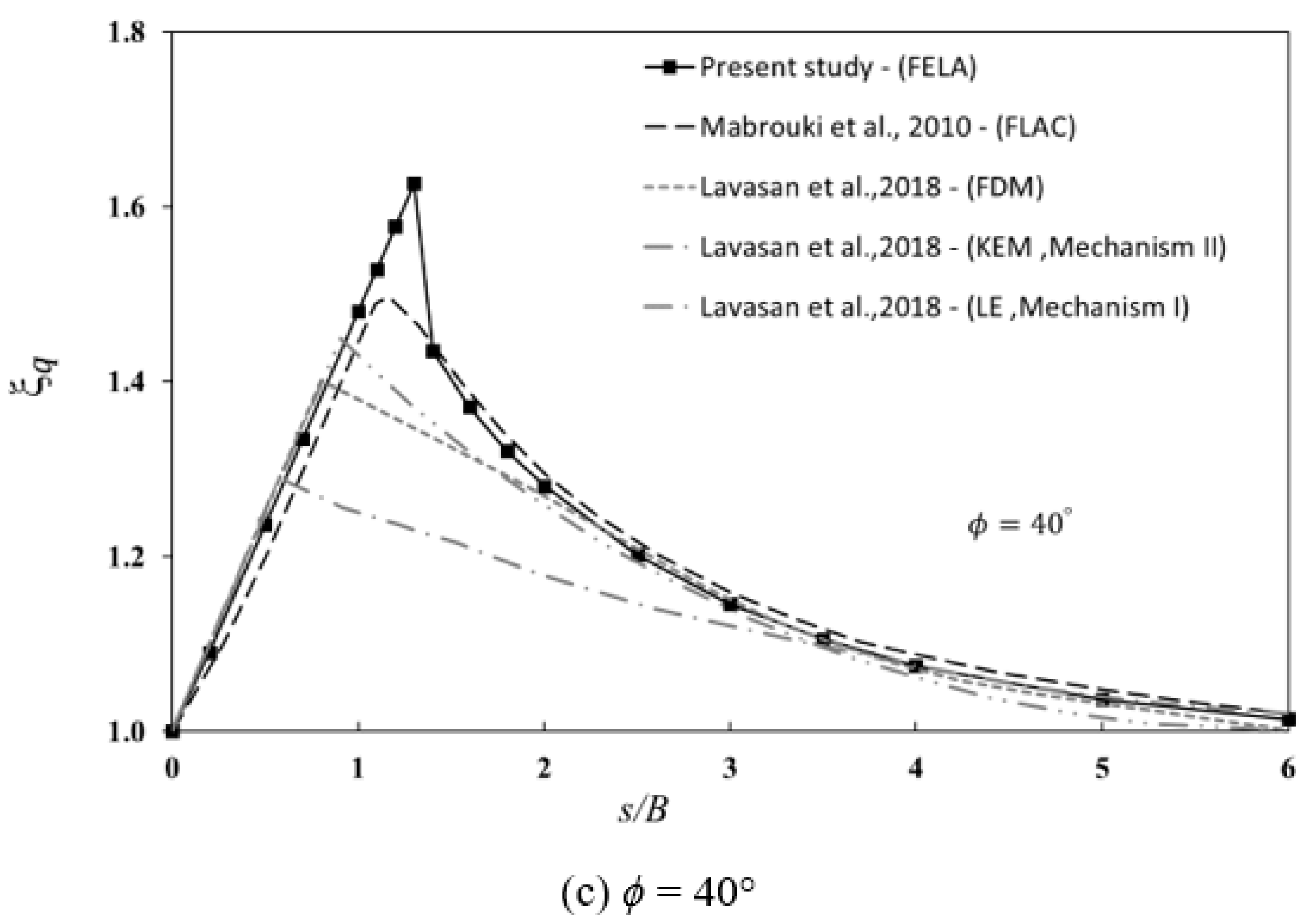
Numerical comparisons of
ξq for different values of
ϕ (30°, 35°, and 40°) are presented in
Figure 8a–c. In
Figure 8a, for
ϕ = 30°, the finite difference results (FDM) of Mabroukei et al. [
6] were in good agreement with the present FELA results. Nevertheless, those reported by the limit equilibrium and the upper-bound methods were well under the agreed curve, and the results cannot be used in practice. As
ϕ increased, the differences became greater (see
Figure 8b,c for
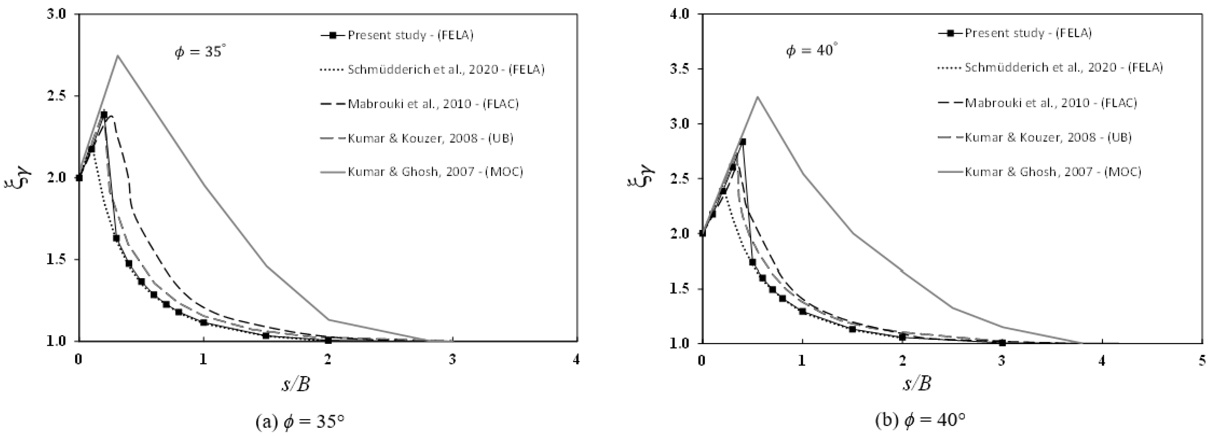
ϕ = 35° and 40°, respectively). Finally, comparisons of the efficiency factor
ξγ for
ϕ = 35° and 40° were made with those published by Mabrouki et al. [
6], Kumar and Kouzer [
5], Schmüdderich et al. [
33], and Kumar and Ghost [
3], and they are shown in
Figure 9. The numerical results showed that the present solutions agreed well with all other published solutions at larger
s/B ratios. The results of Kumar and Ghost [
3] with mechanism IV are considered to be over-conservative, as they were consistently higher than ours. It should be noted that this is the first study to employ FELA with an adaptive mesh refinement to compute rigorous bound solutions. As indicated by several researchers (e.g., [
19,
20,
21,
22,
23,
24,
25,
26,
27,
28]) who also used the feature of adaptive mesh refinement, the differences between the LB and UB solutions became neglectable, which led to more accurate limit state solutions of several stability problems.
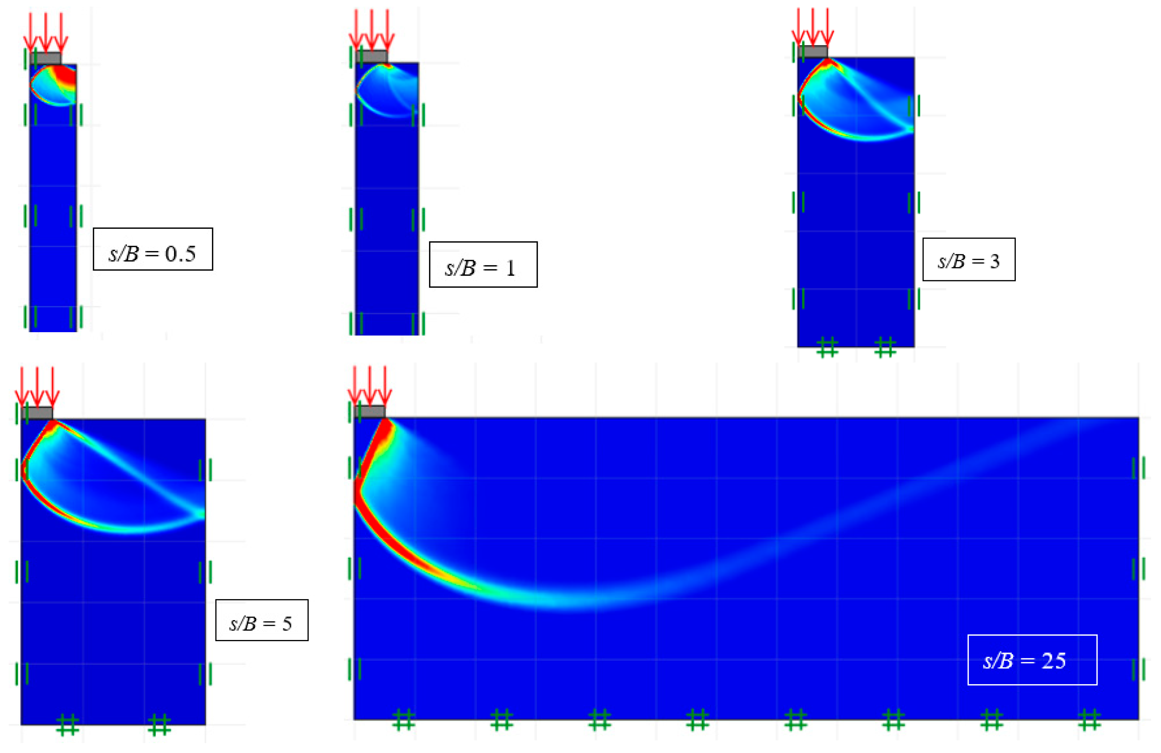
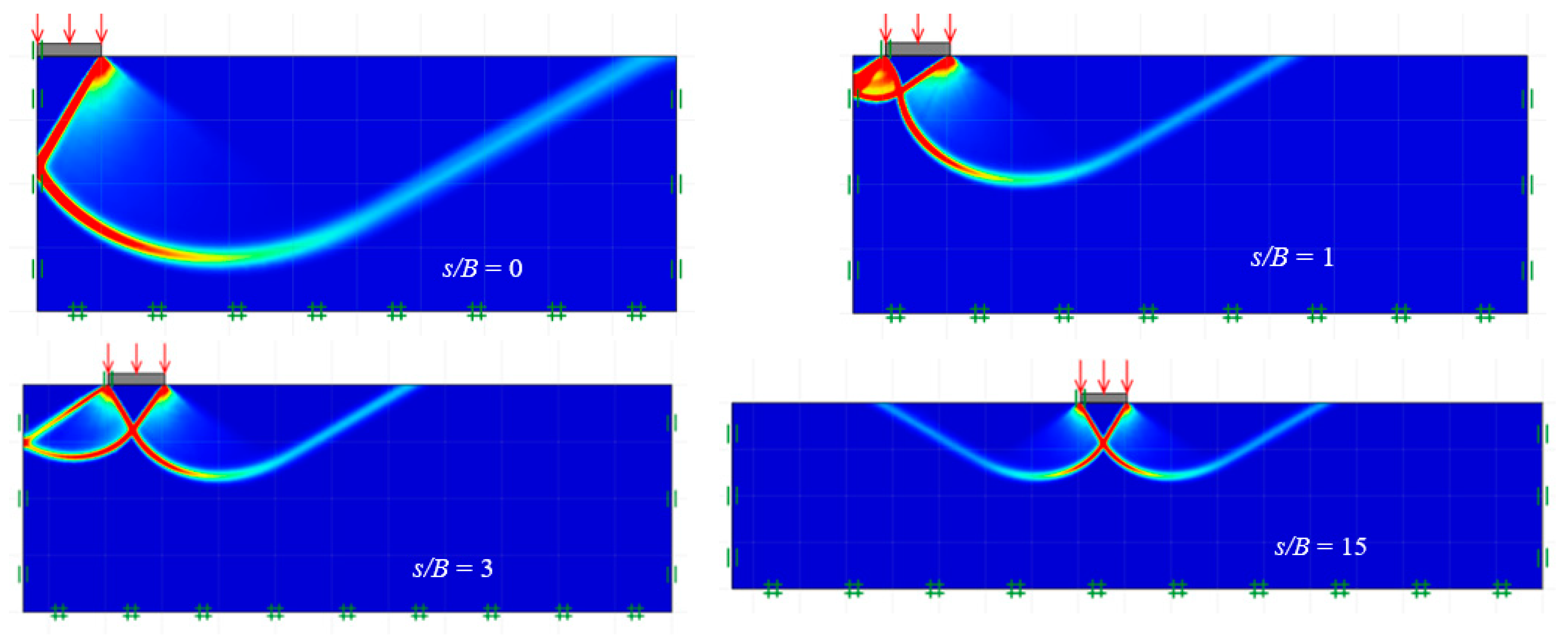
The failure mechanisms for
ξc (
c ≠ 0,
γ =
q = 0),
ξq (
q ≠ 0,
c =
γ = 0), and
ξγ (
γ ≠ 0,
c =
q = 0) are presented in
Figure 10,
Figure 11 and
Figure 12. The plots are for
ϕ = 30°. For brevity, only the plots of shear dissipation contours for the various distance ratios (
s/B) are shown. When
s/B = 0, the problem of two footings turns into a single footing, where the failure is in a Prandtl-type pattern. Noting the symmetrical domains in the figures, the overlapping effects were particularly noticeable at minimal
s/B values. This overlapping action may improve the capacity of the footing, but the downside would be the possible uneven footing settlement. On the other hand, as expected, the larger the
s/B ratio, the smaller the footing interference. Prandtl-type failure mechanisms were obtained for large values of
s/B, as can be seen in
Figure 10,
Figure 11 and
Figure 12.
5. Multiple Interfering Footings
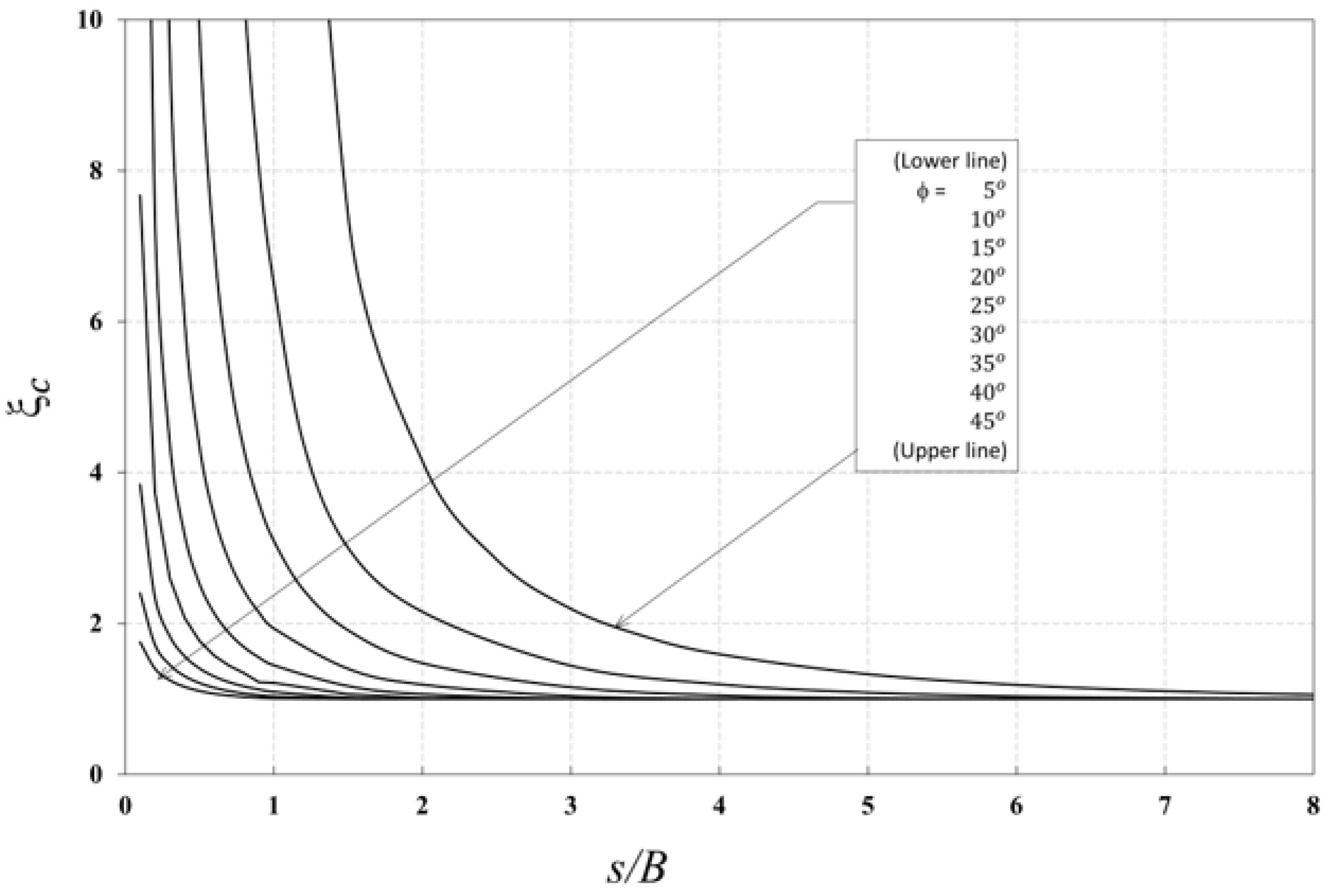
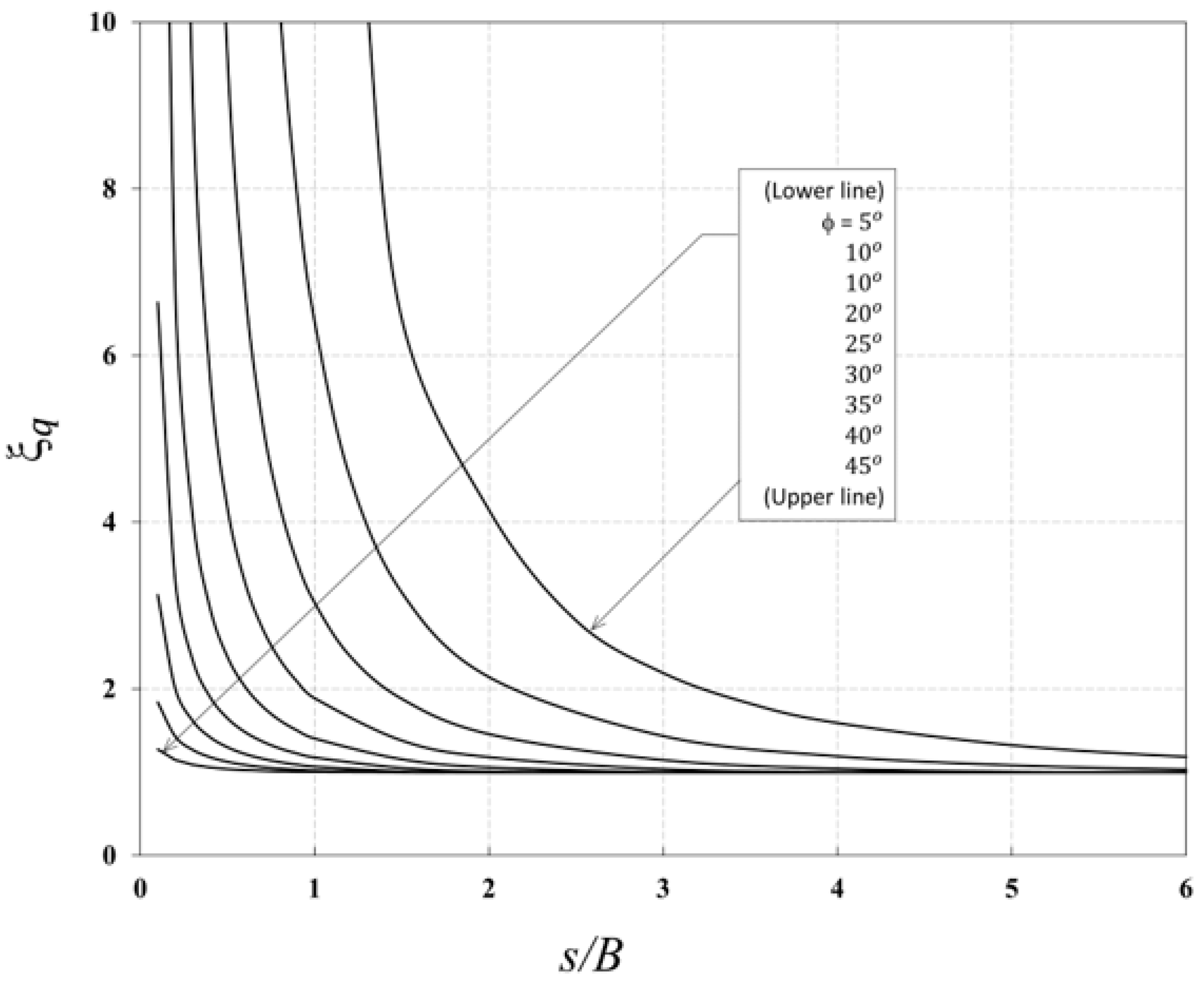
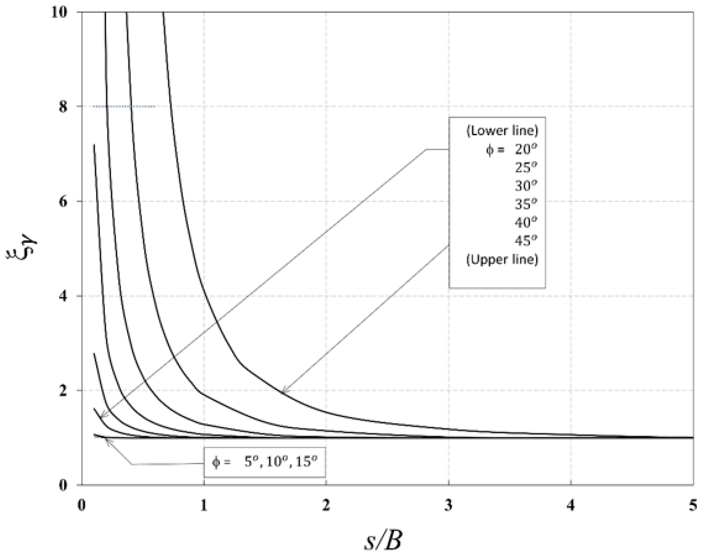
The variation in efficiency factors
ξc,
ξq, and
ξγ with
s/B for multiple interfering strip footings are presented in
Figure 13,
Figure 14 and
Figure 15, respectively. These figures are for the various values of the internal friction angle (
ϕ = 5° to 45°). The initial value of the efficiency factors at
s/B = 0 was an intriguing result that differed from the previous results with two interfering strip footings. All three efficiency factors
ξc,
ξq, and
ξγ had infinite values as
s/B approached zero since the problem turned into a single footing with B being infinity compressed everywhere on the soil surface. Once the ratio of
s/B was further increased, it led to decreasing efficiency factors owing to a surface gap opening for soil masses to move upwards. Depending on the value of
ϕ, the three efficiency factors
ξc,
ξq, and
ξγ decreased significantly to unity at different s/B values. A hyperbola-type smooth curve was observed. The numerical results in this study also showed that a larger value of
ϕ led to higher values of the efficiency factors.
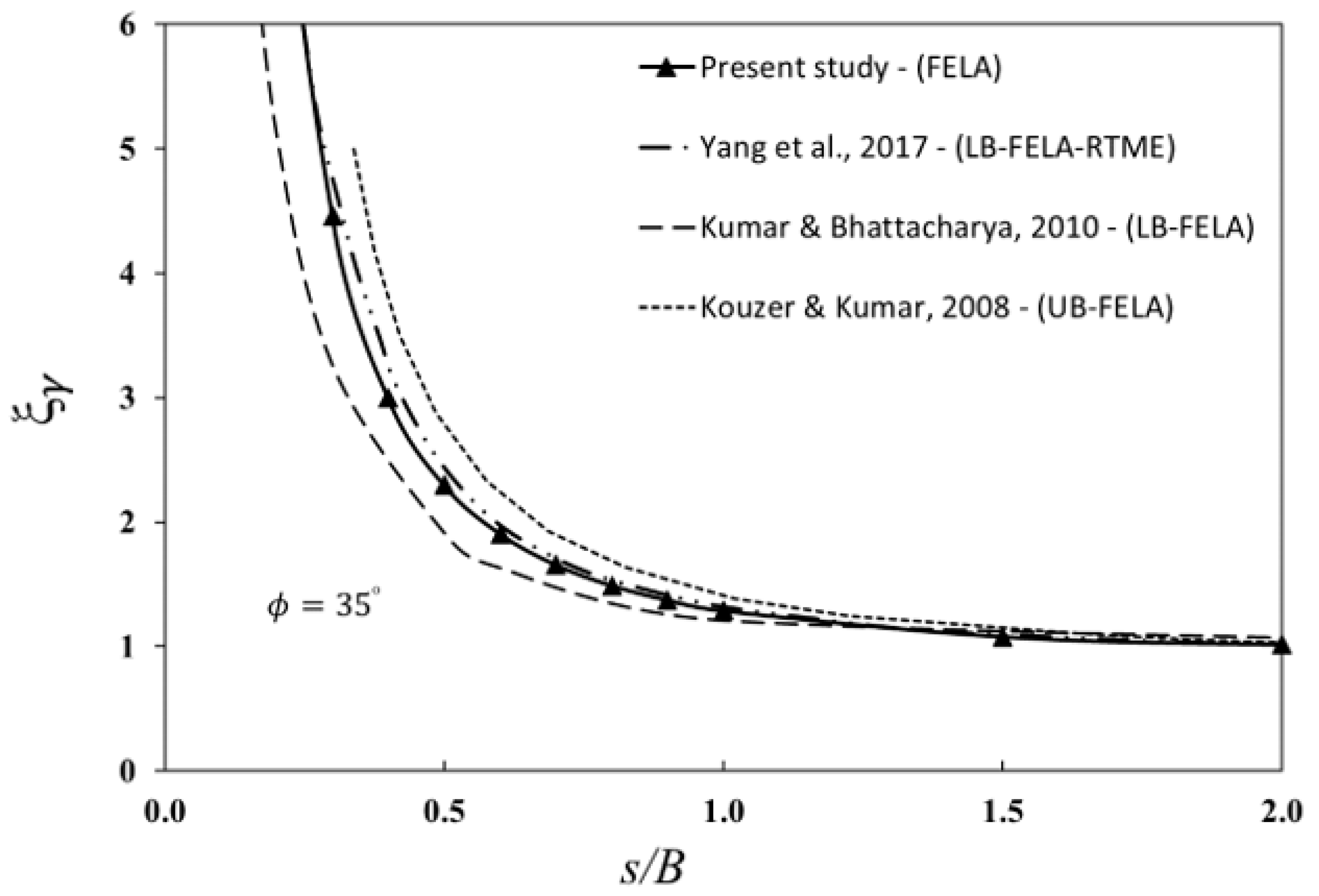
A comparison of the efficiency factor
ξγ of multiple interfering strip footings is presented in
Figure 16. The comparison is for
ϕ = 30°. In general, the current analysis and the previously reported solutions were found to be in good agreement. The numerical results of Yang et al. [
12] were remarkably similar to the findings of the current investigation, while Kouzer and Kumar [
10] predicted larger values and Kumar and Bhattacharya [
11] had lower values than ours.
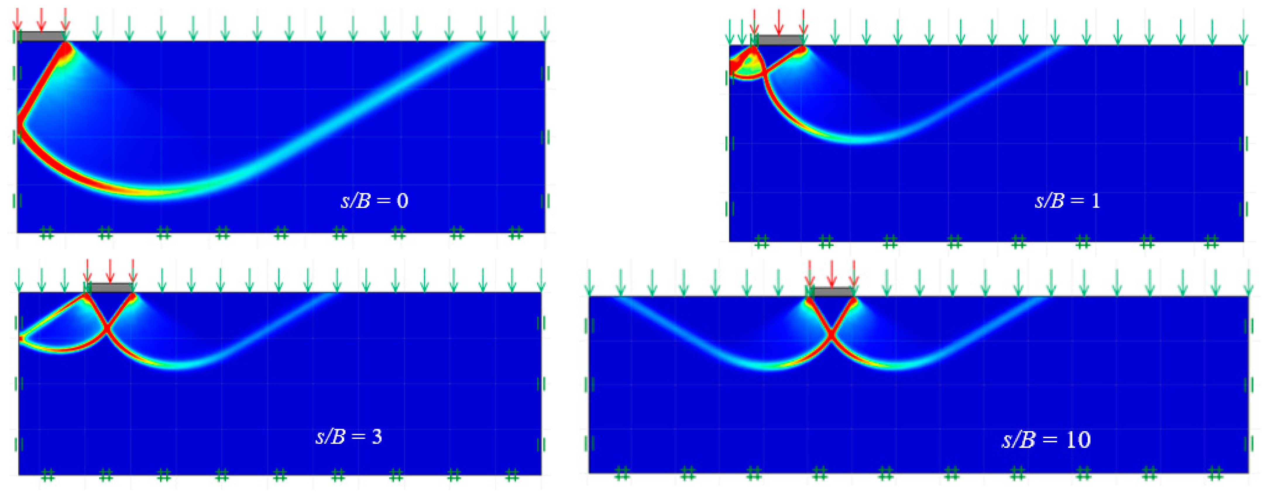
The failure mechanisms of multiple interfering strip footings are demonstrated in
Figure 17,
Figure 18 and
Figure 19 for
ξc (
c ≠ 0,
γ =
q = 0),
ξq (
q ≠ 0,
c =
γ = 0), and
ξγ (
γ ≠ 0,
c =
q = 0), respectively. The chosen comparison is for
ϕ = 45°. It is worth noting that the problem of multiple footings has symmetrical planes on both the left and right sides. The resulting efficiency factors are significantly larger than those with two interfering footings. Consequently, it may indicate that overlapping has a positive effect on the overall bearing capacity of multiple footings owning to the lateral resistance provided by the nearby footings. This study broadly confirmed the understanding of the effects of the two key parameters
ϕ and
s/B for the problem of multiple interfering strip footings on cohesive–frictional soil.
6. Examples
The above study provides complex solutions that require further explanation on how to use them practically in the field. Therefore, this section includes several examples to demonstrate the superposition process involved in calculating the bearing capacity of closely spaced footings using Equation (3). The following three examples are for frictional soil and cohesive–frictional soil with a two-footing system as well as for cohesive–frictional soil with a multiple-footing system.
Example 1. Frictional soil with surcharge loading (two footings)
Two strip footings have the same width of B = 1.00 m, and the edge-to-edge distance of the two interfering footings is s = 0.30 m. The design parameters are given as the soil unit weight of γ = 18 kPa and the soil’s internal friction angle of ϕ = 40°. The soil cohesion (c) is zero, and the surcharge loading is q = 18 kPa.
Given
ϕ = 40°, the values of
Nc,
Nq, and
Nγ from
Figure 3 are 74.77, 63.84, and 84.09, respectively. The efficiency factors can be determined as
ξc =1.15,
ξq = 1.15, and
ξγ = 2.65 from
Figure 4,
Figure 5 and
Figure 6, respectively (
ϕ = 40° and
s/B = 0.3). By substituting these into Equation (3), the bearing capacity of two closely spaced footings can then be calculated as
pu,m = (18 × 1.15 × 63.84) + (0.5 × 18 × 1 × 2.65 × 84.09) = 3327.13 kPa.
Example 2. Cohesive–frictional soil with surcharge loading (two footings)
In this example, the two-strip footing has a width of
B = 1.50 m, and the spacing is
s = 0.60 m. The design parameters are given as the soil unit weight of
γ = 18 kPa and the soil’s internal friction angle of
ϕ = 40°. The soil cohesion is
c = 15 kPa, and the surcharge loading is
q = 18 kPa. Given
ϕ = 40°, the values of
Nc, Nq, and
Nγ from
Figure 3 can be determined as 74.77, 63.84, and 84.09, respectively. The efficiency factors can be obtained from
Figure 4,
Figure 5 and
Figure 6, respectively, for the case of
ϕ = 40° and
s/B = 0.4, and they are
ξc = 1.20,
ξq = 1.20, and
ξγ = 2.9. Using Equation (3), the bearing capacity of two closely spaced footings can then be calculated as
pu,m = (15 × 1.2 × 74.77) + (18 × 1.2 × 63.84) + (0.5 × 18 × 1.5 × 2.9 × 84.09) = 6016.93 kPa.
Example 3. Cohesive–frictional soil with surcharge loading (multiple footings)
In this example, the multiple strip footings have the same width of
B = 1.50 m, and they are equally spaced, with
s = 3.00 m. The design parameters are given as the soil unit weight of
γ = 18 kPa and the soil’s internal friction angle of
ϕ = 35°. The soil cohesion is
c = 15 kPa, and the surcharge loading is
q = 20 kPa. Given
ϕ = 35°, the values of
Nc,
Nq, and
Nγ from
Figure 3 are 45.85, 33.17, and 34.21, respectively. The efficiency factors can be determined as
ξc = 1.47,
ξq = 1.46, and
ξγ = 1.00 from
Figure 13,
Figure 14 and
Figure 15, respectively, for
ϕ = 35° and
s/B = 2.00. By substituting these into Equation (3), the bearing capacity of multiple closely spaced footings can then be calculated as
pu,m = (15 × 1.47 × 45.85) + (20 × 1.46 × 33.17) + (0.5 × 18 × 1.5 × 1.00 × 34.21) = 2441.39 kPa.
7. Conclusions
This paper considered one of the classic problems in geotechnical engineering, which is the problem of closely spaced footings. It was undertaken to study the interference effects of closely spaced footings on cohesive–frictional soil. The study set out to estimate the efficiency factors ξc, ξq, and ξγ, which can be used to evaluate the bearing capacity of closely spaced footings. This problem is similar to the cases of closely spaced piles, as the efficiency factors are required in the design of group piles. To calculate the results, lower-bound (LB) and upper-bound (UB) finite-element limit analyses (FELA) were employed to provide accurate solutions for the efficiency factors of closely spaced footings problems. Two cases were considered in this study: two closely spaced strip footings and multiple closely spaced strip footings. The underlying soils were cohesive–frictional materials, where both cohesion and the friction angle were taken into account.
With advanced finite-element limit analysis, it has been shown that the efficiency factors ξc, ξq, and ξγ are functions of the internal frictional angle (ϕ) and the spacing ratio (s/B). It was noted that the failure mechanisms were highly affected by the two key parameters (ϕ and S/B). Several comparisons were made with published solutions, and design charts covering wide ranges of the two parameters were produced for practical uses. In addition, the failure mechanisms of the two closely spaced strip footings and the multiple closely spaced strip footings were discussed. These failure mechanisms are of great interests to foundation engineering practitioners. Three examples were also presented to demonstrate the process of estimating the bearing capacity of closely spaced footings. The present findings were comparable to prior solutions, boosting user confidence and allowing for the creation of design charts for practical applications. This study adds to a growing body of literature on the stability of closely spaced soil structures. Future research work is needed for settlement design, considering the possibility of uneven settlement due to the overlapping effect. An experimental program can be established in the future to compare the results with our rigorous UB/LB solutions.


 ,
, 

