Article

Research on Film Insulation Technology for Artificial, Open Water Delivery Canals Based on Solar Heat Radiation Utilization

1
Nanjing Hydraulic Research Institute, Nanjing 210024, China
2
State Key Laboratory of Hydrology-Water Resources and Hydraulic Engineering, Nanjing 210098, China
3
College of Water Resources and Architectural Engineering, Northwest A&F University, Yangling, Xianyang 712100, China
*
Authors to whom correspondence should be addressed.
Sustainability 2022, 14(9), 5720; https://doi.org/10.3390/su14095720
Submission received: 11 April 2022 / Revised: 4 May 2022 / Accepted: 5 May 2022 / Published: 9 May 2022
(This article belongs to the Section Hazards and Sustainability)

Abstract

:
A measure of insulation film floating on the water surface was put forward to solve the problems of ice damage to water delivery canals during the winter operation period in cold regions. Firstly, a circulating flume test system was designed in an indoor radiation- and temperature-controlled environment. Secondly, five groups of comparative tests were carried out according to different application scenarios. Lastly, combined with the experimental data, the radiative degree-day method was used to calculate the ice thickness growth under the film. The results show that, in a sufficient radiation condition, a membrane can effectively melt the canal ice and prevent ice formation. In a limited radiation condition, a membrane can delay the ice sealing time and reduce the ice thickness, avoiding ice thrust damage to canal lining. The ice thickness growth formula can predict the development process of water and ice thickness under this technique. The research provides certain theoretical guidance and practical significance for the combination of solar thermal technology and water delivery engineering in cold regions.

1. Introduction

Long-route artificial water diversion canals and channels are regarded as some of the most effective measures available to alleviate water supply and demand issues in water-scarce Chinese cities [1,2]. In cold regions, water delivery by canals and channels during winter faces a frigid climate. Due to the high freezing index, ice slush in the canals rapidly develops and forms ice cover that is too heavy and affects the water flow; furthermore, it can cause serious damage to the canal structure [3]. When the temperature fluctuates frequently between positive and negative in winter, that is, in warm–cold regions, the ice cover becomes unstable and breaks easily. There is a risk that the broken ice cover may come together again downstream of the canal to form an ice jam and block the flow [4,5]. Therefore, the efficiency of the water supply and the safety of the canal in winter in cold regions face great challenges [6]. It is imperative to innovate the insulation technology of canal water to improve its water supply capacity and safety in winter in cold regions.
Solar energy is recognized as an economical and accessible natural heat source [7]. At present, the method of using a thin film or vacuum tubes to collect solar heat to heat water is widely used in seawater desalination [8]. The technology of water heating by covering the surface with a film to absorb the solar heat radiation has also been widely applied in building hot water supplies and swimming pool water heating. In the application cases above, the water content is limited and still, and the water can be completely covered by the film so that the film provides significant thermal insulation and heat absorption effect, and the water temperature can be raised to 60–80 °C [9,10,11]. In-depth research has been carried out on thin film materials, the optimization of heat collection structures, and phase change heat storage materials [12,13]. Regarding water supply canals, the North Xinjiang water supply project in China, for the first time, tried to achieve thermal insulation for the canal flow water by adding a fiber-reinforced plastic composite structure to form a sunshine greenhouse [14]. However, due to the high freezing index, wind, and snow load, the structure of the sunshine greenhouse was too complex, and the project cost was too large [15] so was not widely used for long-distance water supply canals. Therefore, a method using thin film material to absorb sunlight heat might be a somewhat economical and reasonable choice. At present, this kind of measure has only been applied to static water bodies, and the research on its heating efficiency and layout methods with regard to canal flow water is still insufficient.
This study aimed to solve the water channel damage caused by heavy ice cover in extremely cold regions or ice plugs caused by broken, unstable ice cover in warm–cold regions. For the above reasons, it is important to insulate the canal water by the full use of solar radiation in cold regions. To meet the thermal insulation requirements of artificial, open water delivery canals, a new water heating measure was designed with a thin film floating on the canal water surface to absorb the solar radiation and transfer the absorbed heat into the water body during the day and block heat loss during the night. To get the best result, black fish-scale PVC film material with high heat absorption and low radiation was selected and was spread and floated on the water surface of the canal by winch. Then, the artificial canal water delivery model experiment was designed in a low-temperature radiation environment. In the experiment, the effect of the heating and thermal insulation of the film on the water was researched according to different film materials, radiation angles, and radiation time. Finally, based on the experimental results and the theory of river ice mechanics, a prediction model of water ice thickness growth in a film-covered canal was established, and two different application scenarios for the film were put forward.

2. Test Devices and Methods

2.1. Circulating Water Tank Device

Water flow icing has been studied by flume experiments for a long time. The long, straight flume model can be used to study the flow behavior and the accumulation movement in the flow at room temperature [16,17]. Because the low-temperature storage space was limited and annular flume test devices are often chosen to simulate the water flow situation and ice development [18,19], to realize the low-temperature water delivery conditions, an annular flume test device was developed in a low-temperature environment chamber. The chamber provided a temperature-controlled environment within the range of −40 °C to 40 °C, and heat radiation lamps, with heat power of 500 W in each array, were distributed on the top of the chamber. The annular flume device consisted of a U-shaped water sink welded with steel plates and a pipe pump, with the length of the straight line segments being 2 m each, and the radius of curved arc being 1.5 m. The U-shaped sink had a half-trapezoidal section, and its inner layer was coated with anti-seepage paint and lined with ceramic tiles, and the inner side of the outer steel plate was pasted with insulation board. The top width of the sink was 57.6 cm, and the bottom width was 10 cm, and the height was 45 cm, which meant that the scale of the model to the prototype was 1:5. In order to meet the similarity requirement, the scale of time was set as 1:5, and the scale of flow rate was 1:1. The pipeline pump with a YE3-180L-4 three-phase asynchronous motor, with rated speed of 1400 r/min, was adopted to change the flow velocity in the tank by adjusting the motor speed. A rectangular, deep water tank was set between the pipeline pump and the U-shaped water sink with two iron nets set at the connection to smooth the U-shaped groove water flow. The composition and structure of the device are shown in Figure 1.

2.2. Experimental Data Acquisition Scheme

Water-proof Pt100 temperature sensors, with ranges of −50~300 °C and accuracy within 0.1 °C, were used to measure the water temperature at different locations and different depths. RY-EBN-1 solar radiation sensors were used to measure the radiation received and reflected by the water and film surface. The measurement range of the solar radiation sensors was 0~2000 W/m2, and the working environment was −40~65 °C. A LS300-ALGY-II rotary-type current meter was used to measure the flow velocity of the canal water. The velocity range of the current meter was 0.01~4.00 m/s, and the flow measurement error was less than 1.5%. Ice thickness was measured with vernier calipers and recorded every 1 h.

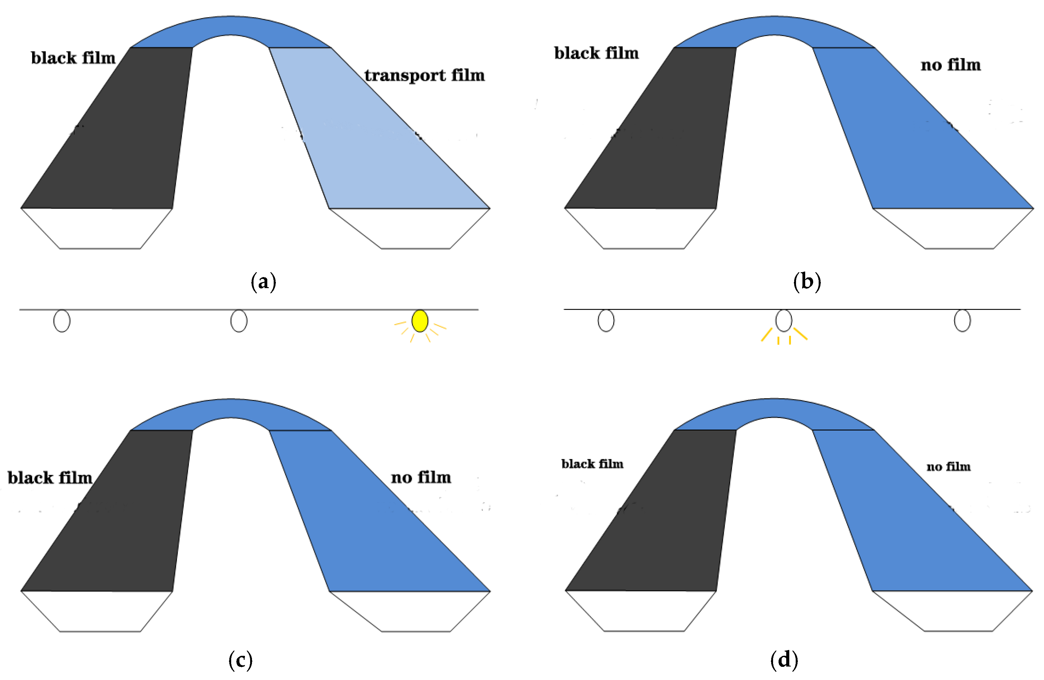
2.3. Test Scheme Design

Before the test, the pump power was adjusted to stabilize the water flow at a depth of 0.3m and velocity of 0.15 m/s. The temperature sensors were fixed 1 cm and 10 cm under the water, respectively. During the test, the ice thickness was measured with vernier calipers by drilling through the ice surface. The amount of radiation received and reflected by the water or film surface was measured with the solar radiation sensors, and the net absorption was calculated. At the beginning, the room temperature was set to 0 °C, and the pump was started to form a circulatory water flow until the water temperature dropped to 0 °C. Then, the ambient temperature was set to −9 °C and maintained, and the temperature of water and the ice thickness were recorded every 1 h. To study the thermal insulation effect of the PVC film material on the canal water under different solar radiation conditions, five groups of different control experiments were designed in the flume. In test 1, to compare the heating efficiency of black and transparent PVC films, the black and transparent PVC films were separately laid on the water surface of the left and right side of the U-shaped slot. The heat radiation lamp at the middle-top of the slot was opened so that it could supply equal heat radiation to each side of the water surface (Figure 2a). In test 2, to study the heating efficiency of black PVC films and bare water, the environment and the flow condition were maintained while the transparent PVC film on one side of the slot was removed following test 1 (Figure 2b). In test 3, to study the absorption of solar radiation by the black film and the resulting water temperature and ice development at a lower sun angle, the heat radiation lamp near the right side, where no film covered the water, was opened, while the middle-top lamp was closed following test 2 (Figure 2c). In test 4, to study the preservation effect of the film at night, all heat lamps were closed, and the environment temperature was maintained at −9 °C (Figure 2d). In test 5, to study the preservation and heat effect of the black film when day and night alternated, the environment temperature was cyclically changed between −9 °C and 2 °C within 7 h, and the radiation lamp was turned off and on accordingly (Figure 2d). The indoor model and the film layout are shown in Figure 3.

3. Test Results and Analysis

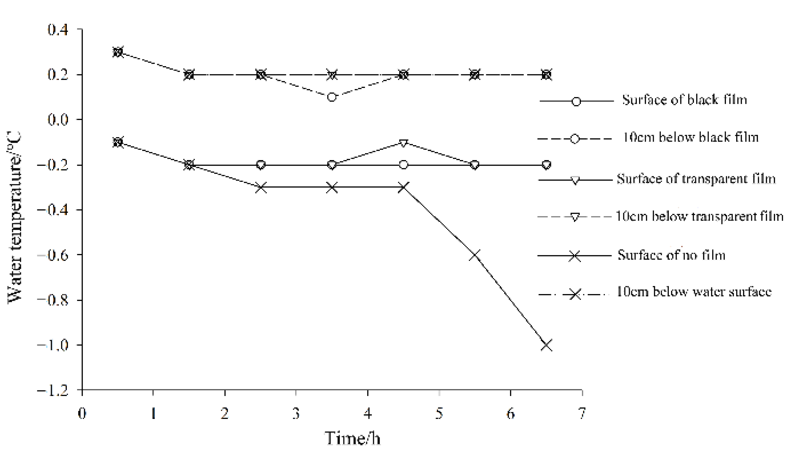
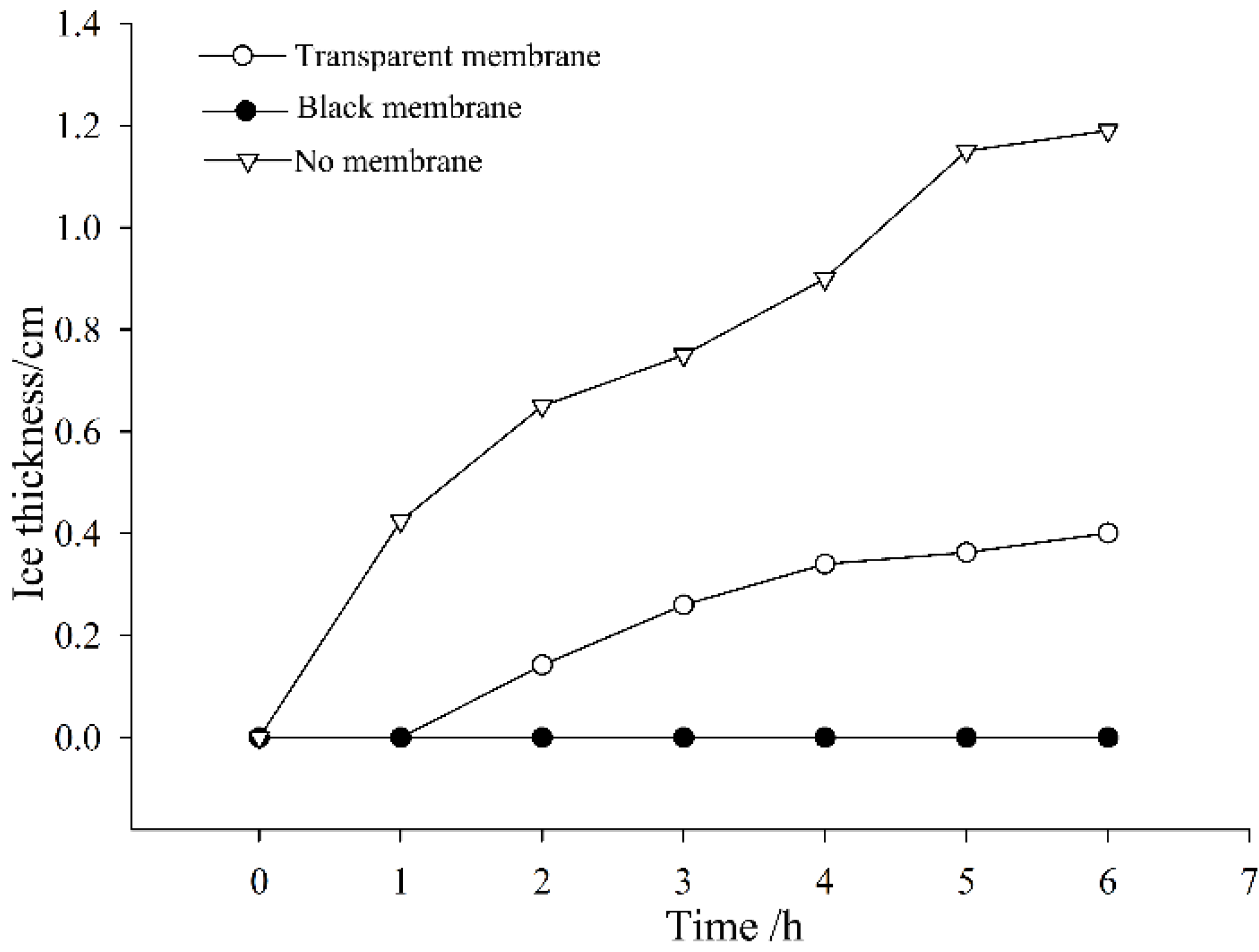
3.1. Heating Effect of Different PVC Films

In tests 1 and 2, the radiative heat received by the black film, transparent film, and water surface was measured to be 36 W/m2, and the reflection radiation was 2.8 W/m2, 12.4 W/m2, and 12.8 W/m2, respectively. The net radiation absorption of the black film was 1.4 times that of the transparent film and water surface. The water temperature duration under different film mulching conditions is shown in Figure 4. The water temperature when covered by the black film and transparent film was almost the same and higher than that without the film. As the test progressed, the amounts of thermal radiation absorbed by the water, heat produced by the phase change, and heat dissipated by the water reached equilibrium so that the water temperature remained unchanged until ice cover formatting. Due to this reason, the temperature of the water surface, without film, stayed near freezing point at first, then decreased until the ice sheet thickened and wrapped around the temperature sensors. The deep water temperature (10 cm under the surface) was consistent both in the filmed and bare regions and always higher than the freezing point.
The ice thickness under the film was measured. As shown in Figure 5, water under the black film was always free of ice. Water under the transparent film was free of ice at the beginning but slowly froze 1 h later and formed an ice sheet with a maximum thickness of 0.40 cm. For the water with no film, the ice rapidly hung from both sides of the slot and eventually formed a fully frozen ice sheet with an average thickness of 1.19 cm.

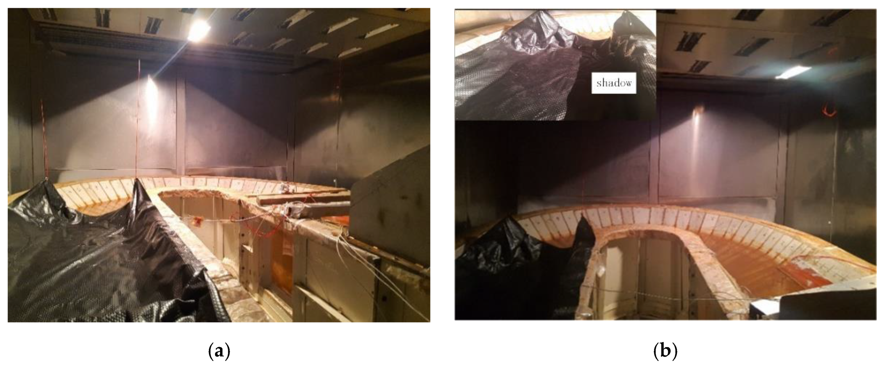
3.2. Influence of Low Incident Angle and Shadow on Film Heat Efficiency

In test 3, the absorption efficiency and heating effect of black film on the water were studied under the condition of receiving low-angle radiation with shadow on the film surface compared to a bare water surface with vertical incidence (Figure 3b). The incident radiation measured was 7.8 W/m2 for the black film, and the reflection radiation was 0.7 W/m2; hence, the net absorption was 7.1 W/m2 for the irradiated region but 0 for the shaded region. In comparison, the net absorption of the bare water surface was 38.6 W/m2, which was 5.4 times that of the black film surface. However, the temperature of the water 1 cm below the film was equal to that with no film, and the temperature 10 cm below the film was slightly higher than that with no film (Figure 6). As for the ice development, see Figure 7; there was no ice in the shaded region below the film at the beginning, but the ice formed 1 h later, and its thickness increased rapidly, while there was no ice in the lit region throughout the test. As a comparison, the water surface with no film but plenty of heat radiation was frozen to form ice cover at a constant rate. The results showed that the black film had an excellent radiation utilization rate that prevented the water forming ice cover even when receiving a very small radiation amount. At the same time, the film had an insulation effect so that the ice was thinner than that in the bare water of test 1 and test 2 and was nearly as effective as the bare water with vertical incidence. For the canal with shading effect, the film melted the ice in the illumination area and slowed down the development of ice thickness in the shaded area.

3.3. Influence of Diurnal Variation on Film Heat Efficiency

In test 4, the negative temperature was maintained, and the radiation lamp was turned off to simulate the operation condition of the canal at night. As shown in Figure 8, both the filmed and bare water formed an ice sheet, but the water temperature remained unchanged when they decreased near to freezing point. With the extension of the freezing time, the ice thickness of the bare water developed beyond the position of the temperature sensors that were 1cm below the water surface, so the measured temperature declined continuously. For the filmed water, the ice thickness grew slowly (delayed 1 h), and the water temperature measured was always near to the freezing point. At the end of the test, the thickness of the ice sheet reached 1.35 cm in the bare water and 0.75 cm in the filmed water. Under the condition of no radiation, the ice thickness was reduced by about 45% due to the insulation of the film, which, if applied, could effectively alleviate the problem of an ice jam disaster caused by ice sheet thickness in an extremely cold environment.
In test 5, the environment temperature periodically alternated between −9 °C and 2 °C according to the average daytime and night temperature in early winter (November–December) in Northern Xinjiang of China. The radiation lamp was turned off and on to simulate the diurnal variation. The temperature and ice thickness of the filmed water and bare water were observed, as shown in Figure 9, through five alternating temperature and radiation periods in 35 h. No ice formed in the region where the film covered the water, and the surface temperature fluctuated with an ambient temperature around 0 °C. As a contrast, the ice thickness gradually increased to 2cm in the bare region, and the surface temperature of the water dropped to freezing point and remained stable, then began to drop to −3 °C until the ice cover thickened and wrapped around the sensors. It can be seen that, under the comprehensive condition of alternating temperature and alternating radiation, the film warmed and insulated the water alternately and could be used for the purpose of maintaining the ice-free operation of water delivery in early winter.

4. Radiation-Day Model for Calculating Ice Thickness in a Film-Covered Canal

4.1. Calculation Model

To consider the effect of radiation on ice sheet growth, the radiation-day model was modified on the basis of the traditional freeze-day model to fit the experimental results and provide a design reference for the application of the film insulating technology. The evolution of the ice sheet simplified by the radiation model was essentially the result of heat exchange [20,21]. The main thermal processes of the ice cover were radiative heat transfer and heat exchange processes mediated by the ice cover.
The radiation heat transfer was studied first. The energy of solar radiation that can reach the ground directly is expressed as the total solar radiation Rs (unit: J/m2), which is composed of direct radiation Rsb and scattered radiation Rsd. The energies radiate outwards by the ground, and atmosphere is expressed as surface radiation RLu and atmospheric inverse radiation RLd, respectively. The difference between the total solar radiation and the atmospheric inverse radiation absorbed by the surface area and the radiation emitted by the surface area is the net surface radiation Rn, which is expressed below.
R n = ( R sb + R sd ) ( 1 ε ) + R Ld R Lu
where ε is the reflectance of solar radiation by the earth (unit, 1).
In this paper, the radiation source used in the experiment was not sunlight but the radiation lamps, and their radiation quantity Rs was directly measured by the radiometers. Meanwhile, the atmospheric inverse radiation RLd was ignored in the laboratory environment. The above formula was simplified as:
R n = R s ( 1 ε ) R Lu
where Rs is the acceptance radiation measured in the laboratory, and RLd is the reflection radiation measured in laboratory.
According to the definition of the net surface radiation, the heat rate qs (unit: J/m2) obtained (lost) by the radiative heat transfer per unit area of ice cover can be calculated by the following equation:
q s = R n
The direct heat exchange between the water and the atmosphere is transformed into the heat exchange process mediated by ice cover after the water surface freezing. The exchange includes two processes: the heat exchange between the ice cover and the water body qwi and the heat exchange between the ice cover and the atmosphere qi. Considering the radiative heat transfer, the increase or decrease of the ice cover thickness due to the total heat budget is shown below.
q i d t q wi d t q s d t = L i ρ i d Δ h i
where t is the time, unit h; Li is the phase change latent heat between water and ice, unit J/(kg °C); and ρi is the density of ice, unit kg/m3.
Since the experiment in this paper was carried out in flow water, the radiation-day method for flow water was used to fit the experimental results. Hence, qi and qwi in Formula (4) could be calculated as [21]:
q i = k i k a k a h i + k i h a T a
q wi = k w h w T w
where ki is the heat conductivity of the ice (2.24 W/(m·°C)), ka is the heat conductivity of the air (0.026 W/(m·°C)), kw is the heat conductivity of the water (0.58 W/(m·°C)), hi is the thickness of the ice cover, ha and hw are the boundary layer thickness of the air–ice interface and the ice–water interface, respectively, and Ta and Tw are the temperature of the air (−9 °C in the experiment) and the water (0.1 °C in the experiment), respectively.
The differential equation of the ice thickness development for the filmed water could be obtained:
k i k a k a h i + k i h a T a d t k w h w T w d t R n d t = L i ρ i d Δ h i
Δhi (unit: m) is the increment of ice thickness based on the initial thickness h0, and the ice thickness hi could be expressed as:
h i = h 0 + Δ h i
The formula for calculating the ice thickness of the flow water by the radiation day method was sorted out by integrating both sides of Equation (7) and the differential time step.
h i = b + b 2 4 a c 2 a
where a = Liρika, b = Liρi(kiha + kah0) + ζ·ka, c = kikaTaΔt + (ζ·kiha + kah0), and ζ is the difference scheme of time, as below.
ζ = k i k a k a h i + k i h a T a Δ t + R n Δ t k w h w T w Δ t

4.2. Calculation Results

The radiation-day model for calculating the ice thickness of the filmed and bare water was verified according to the results of test 1. The thickness of the turbulent boundary layer of the ice–air interface was valued as 8 × 10⁻⁴ m, and the ice–water interface was valued as 1.2 × 10⁻³ m [22]. To ensure the calculation scheme, the initial ice thickness h0 should be given as a non-zero value; it was 0.01 cm in this paper. The comparisons of the calculated ice thickness with that measured in test 1 are shown in Figure 10. The calculation of the ice thickness of the bare water agreed with the experiment results, and the ice cover developed rapidly at the beginning and then became stable. According to the calculation results, the ice cover formed inescapably in the filmed water, while the water was free of ice in the actual test. This was because the initial ice thickness was not zero in the model. However, the calculated ice thickness was very small and barely grew with time.

5. Discussion

It seemed that film could not significantly improve the temperature of water flowing in the slot in this experiment. The temperature measured for the filmed and the bare water surface was almost the same. The film only maintained constant water temperature when receiving radiation at a negative temperature. This was because the film region was limited, so the water flow under the film absorbed heat transitorily and then flowed out of the film. Even so, the region covered by the black film was free of ice for two reasons. One reason was that the film, isolated from the direct contact between the water and cold air, reduced the further heat loss of the water caused by convection and evaporation. The other reason was that the tiny ice crystals melted rapidly once they floated up to the film surface. The ice crystals could not gather in the film region and form ice cover. Under the simultaneous action of heat preservation and ice melting, no ice formed in the covered region when the water experienced temperature and radiation alternating between day and night, which, if applied, could effectively protect water delivery buildings from ice damage.
The filmed area with shading inevitably formed ice cover in test 4, but the time of ice cover forming was delayed by 1h, and the maximum ice thickness was reduced by 45% compared with the bare water. There was a remarkable phenomenon in the test where the ice cover surface of the bare region was rough, and the ice crystal arrangement was irregular, while the cover surface was smooth under the film and had regular and compact ice crystal arrangement (shown in Figure 11). It was presumed that the ice cover formed was more stable under the film. At present, there is no relevant explanation for the difference of the ice cover morphology between the filmed and bare water, so it is worthy of further study in subsequent experiments.
Through the tests, two different application cases of the film for water delivery canals can be summarized. Case 1: in an extremely cold region or a region with insufficient solar radiation, the film may not be able to melt water ice and prevent ice cover formation. However, the film can be used to delay the freezing time and reduce the thickness of ice cover, which is significant for improving the flow capacity of the canal and protecting the canal structure from damage by heavy ice cover. Case 2: in warm–cold regions or regions with sufficient solar radiation, the film can melt ice in a timely fashion and keep the water delivery canal free of ice. It is dangerous that unstable ice cover can form in water delivery canals in warm–cold regions, and the ice cover can easily break and restructure to form ice jams in the canal. The film-covered canal can eliminate the hidden risk of ice jam in the warm–cold regions.

6. Conclusions

The application effect of the film insulation technology on water delivery canals in cold regions was researched by indoor model tests. Combined with the test results, the principles and applicability of its thermal preservation and ice melting were analyzed. Furthermore, the approximate calculation formula for the water ice thickness prediction of the film-covered canal was deduced. The conclusions are as follows:
(1)
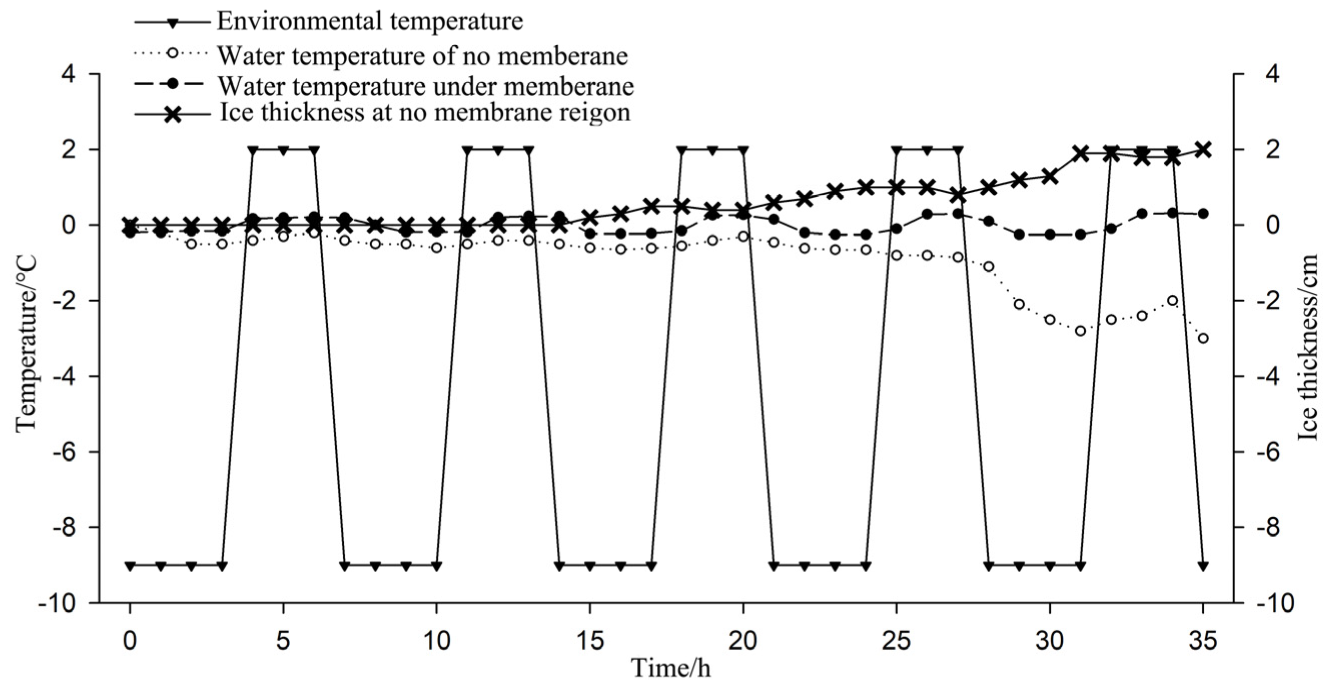
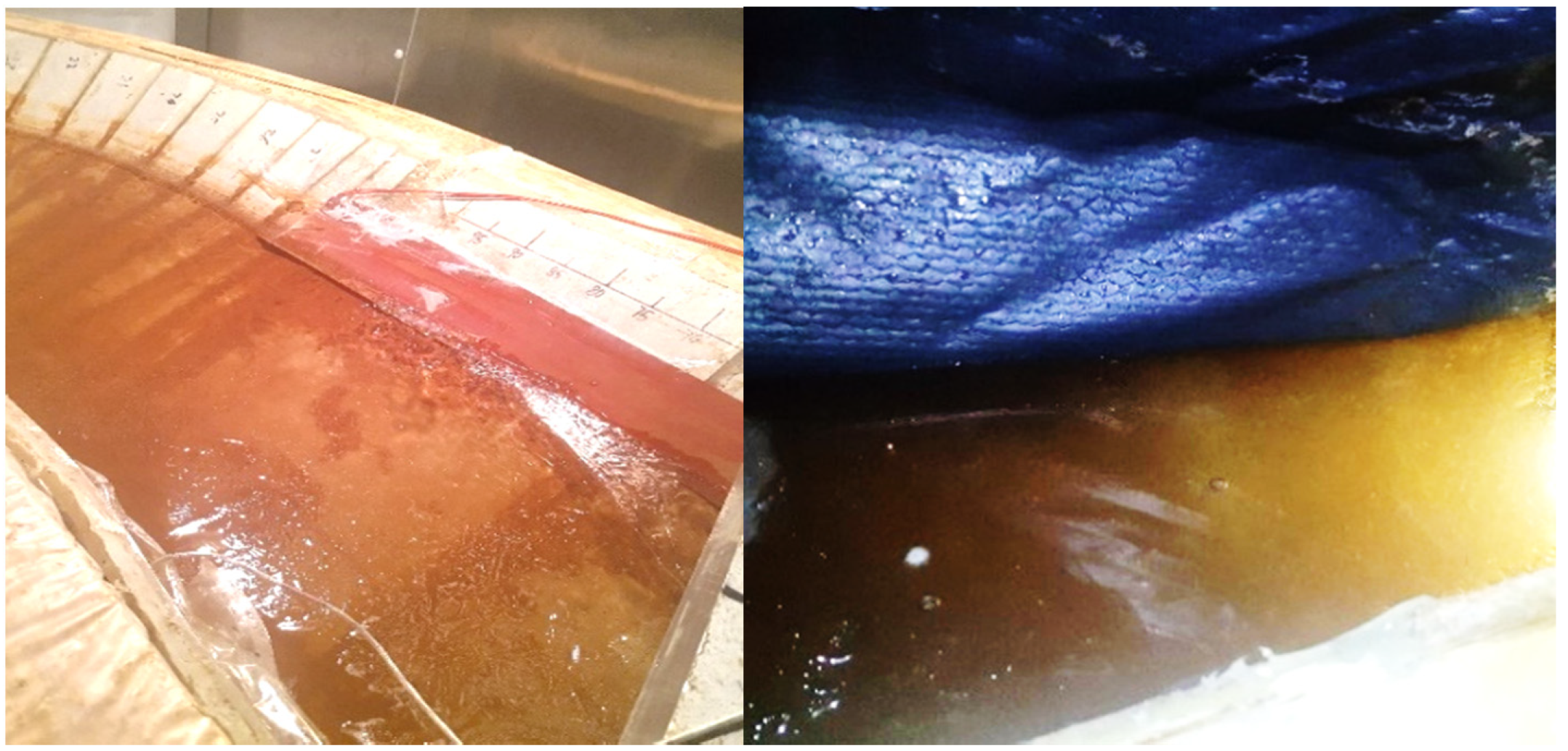
The black PVC film with fish-scale surface had high radiation absorption efficiency and low reflectivity, and the ice melting effect was remarkable. In negative temperatures, the tiny ice crystals melted rapidly once they floated up to the film surface that was receiving irradiation. The film retained thermal heat in the absence of radiation, thus, delaying the formation of ice cover. Under the condition of alternating between radiation and no radiation, the film still melted ice and ultimately remained ice free.
(2)
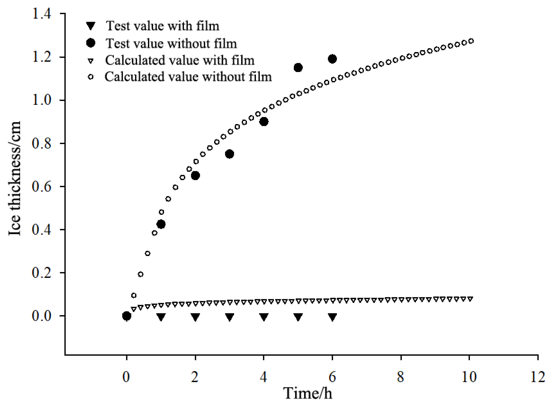
The ice thickness prediction formula of the flow water was derived based on the radiation-day model and was able to evaluate the effectiveness of this technical measure.
(3)
In extremely cold regions or regions with insufficient solar radiation, the film can be used to delay the freeze time and reduce the thickness of ice cover, which is significant for improving the flow capacity of canals and protecting the canal structures from damage by heavy ice cover. In warm–cold regions or regions with sufficient solar radiation, the film can melt ice in a timely fashion and keep the water delivery canals free of ice, eliminating the hidden risk of ice jam.

7. Patents

Zhengzhong Wang, Yi Wang, Xuecai Zhang. A new method for preventing the freezing and evaporation of water delivery channels in cold regions. CN, CN106544990A. Aijun Zhang, Wenyuan Ren, Ruishan Jin, Zili He, Zhengzhong Wang. Model test device and test method for circulating water flow freezing in long-distance diversion channel. CN, CN109540463B.

Author Contributions

Conceptualization, Y.W.; Data curation, Y.W. and H.J.; Funding acquisition, Z.W. and Z.C.; Investigation, C.Z. and X.Z.; Methodology, Y.W. and H.J.; Project administration, Z.W.; Resources, C.Z.; Supervision, Z.C.; Visualization, X.Z.; Writing—original draft, Y.W.; Writing—review & editing, Z.W. and Z.C. All authors have read and agreed to the published version of the manuscript.

Funding

National Key Research and Development Program of China (grant no. 2017YFC0405103). Fundamental Research Funds for the Central Scientific Research Institute (grant no. Y321009). National Natural Science Foundation of China (grant no. U2003108).

Data Availability Statement

The data used to support the findings of this study are included within the article.

Conflicts of Interest

The authors declare that they have no conflicts of interest.

References

  1. Wang, J.; Sui, J.; Chen, P. Numerical simulations of ice accumulation under ice cover along a river bend. Int. J. Environ. Sci. Technol. 2008, 6, 1–12. [Google Scholar] [CrossRef] [Green Version]
  2. Guo, X.; Yang, K.; Fu, H.; Xia, Q.; Wang, T.; Yang, S. Ice processes modeling during reverse water transfer of open canals: A case study. J. Hydro-Environ. Res. 2017, 17, 56–67. [Google Scholar] [CrossRef]
  3. Ge, J.R.; Wang, Z.Z.; Niu, Y.H.; Wang, Y.; Xiao, M.; Liu, Q.H.; Jiang, H.H. Elastic foundation beam unified model for ice and frost damage concrete canal for water delivery under ice cover. Trans. CSAE 2020, 36, 90–98. (In Chinese) [Google Scholar]
  4. Beltaos, S.; Burrell, B.C. Ice-jam model testing: Matapedia River case studies, 1994 and 1995. Cold Reg. Sci. Technol. 2010, 60, 29–39. [Google Scholar] [CrossRef]
  5. Turcotte, B.; Morse, B. A global river ice classification model. J. Hydrol. 2013, 507, 134–148. [Google Scholar] [CrossRef]
  6. Zhang, C.; Cai, Z.-Y.; Huang, Y.-H.; Chen, H. Laboratory and Centrifuge Model Tests on Influence of Swelling Rock with Drying-Wetting Cycles on Stability of Canal Slope. Adv. Civ. Eng. 2018, 2018, 1–10. [Google Scholar] [CrossRef] [Green Version]
  7. Velmurugan, V.; Srithar, K. Performance analysis of solar stills based on various factors affecting the productivity—A Review. Renew. Sustain. Energy Rev. 2011, 15, 1294–1304. [Google Scholar] [CrossRef]
  8. Arunkumar, T.; Sathyamurthy, R.; Denkenberger, D.; Lee, S.J. Solar distillation meets the real world: A review of solar stills purifying real wastewater and seawater. Environ. Sci. Pollut. Res. 2022, 29, 1–25. [Google Scholar] [CrossRef]
  9. Ibezim, J.M.; Owuama, K.C.; Ikebudu, K.O.; Azubuike, J.O.; Anyanwu, O.U. Analysis of Exergy of an Experimental Domestic Scale Solar Water Heating System Situated in Owerri. J. Energy Power Eng. 2021, 15, 87–99. [Google Scholar] [CrossRef]
  10. Chyng, J.; Lee, C.; Huang, B. Performance analysis of a solar-assisted heat pump water heater. Sol. Energy 2003, 74, 33–44. [Google Scholar] [CrossRef]
  11. Ralegaonkar, R.V.; Gupta, R. Review of intelligent building construction: A passive solar architecture approach. Renew. Sustain. Energy Rev. 2010, 14, 2238–2242. [Google Scholar] [CrossRef]
  12. Ying, X.; Liu, D.; Xiang, H.; Ren, S.; Zhu, Z.; Liu, D.; Xu, H.; Cui, F.; Wang, W. Easily scaled-up photothermal membrane with structure-dependent auto-cleaning features for high-efficient solar desalination—Sciencedirect. J. Membr. Sci. 2019, 586, 222–230. [Google Scholar]
  13. Peng, X.; Gu, J.; Zhang, C.; Ni, F.; Liang, Y.; He, J.; Zhang, L.; Ouyang, J.; Kuo, S.-W.; Chen, T. A scalable, low-cost, and robust photothermal fabric with tunable and programmable 2d/3d structures towards environmentally adaptable liquid/solid-medium water extraction. Nano Energy 2019, 65, 104002. [Google Scholar]
  14. Zhao, Q.L.; Ke, M.Y.; An, X.Q.; Qu, Q.L.; Wang, X.P. The Utility Model Relates to a River Cover Device for Nonmetal Heat Preservation and Heating of the Water Conveyance Channels in Saline-Alkali Areas. CN, CN210066652U. 2020. Available online: http://cnipa.gov.cn (accessed on 10 April 2022).
  15. Liu, J.; Gao, J.; Zhao, Q. Failure modes of CFRP pre-tightened single tooth joints under axial cyclic tensile loading. Constr. Build. Mater. 2019, 222, 786–795. [Google Scholar] [CrossRef]
  16. Ardiclioglu, M.; Hadi, A.M.W.M.; Periku, E.; Kuriqi, A. Experimental and Numerical Investigation of Bridge Configuration Effect on Hydraulic Regime. Int. J. Civ. Eng. 2022, 1–11. [Google Scholar] [CrossRef]
  17. Nezhad, H.M.; Mohammadi, M.; Ghaderi, A.; Bagherzadeh, M.; Ricardo, A.M.; Kuriqi, A. Flow resistance and velocity distribution in a smooth triangular channel. Water Supply 2022, 1–12. [Google Scholar] [CrossRef]
  18. Wang, Y.; Qian, Y.U.; Shu, G. Relationship between bed shear stress and suspended sediment concentration: Annular flume experiments. Int. J. Sediment Res. 2011, 26, 513–523. [Google Scholar] [CrossRef]
  19. Bocchiola, D.; Rulli, M.C.; Rosso, R. Flume experiments on wood entrainment in rivers. Adv. Water Resour. 2006, 29, 1182–1195. [Google Scholar] [CrossRef]
  20. Shen, H.T.; Yapa, P.D. A unified degree-day method for river ice cover thickness simulation. Can. J. Civ. Eng. 1985, 12, 54–62. [Google Scholar] [CrossRef]
  21. Lian, J.J.; Zhao, X. Radiation degree-day method for predicting the development of ice cover thickness under hydrostatic and non-hydrostatic conditions. J. Hydraul. Eng. 2011, 42, 1261–1267. (In Chinses) [Google Scholar]
  22. Scheel, J.D.; Kim, E.; White, K.R. Thermal and viscous boundary layers in turbulent Rayleigh–bénard convection. J. Fluid Mech. 2012, 711, 281–305. [Google Scholar] [CrossRef]
Figure 1. Composition and structure of the annular flume device.
Sustainability 14 05720 g001
Figure 2. Schematic diagram of test scheme layout. (a) Test 1, (b) Test 2, (c) Test 3, (d) Test 4 and 5.
Sustainability 14 05720 g002
Figure 3. Laboratory test model and device arrangement. (a) Layout of tests 1,2,4, and 5, (b) Layout of test 3.
Sustainability 14 05720 g003
Figure 4. Water temperature duration under different films.
Sustainability 14 05720 g004
Figure 5. Ice thickness development under different films.
Sustainability 14 05720 g005
Figure 6. Temperature comparison of filmed water with low radiation angle and bare water with vertical incidence.
Sustainability 14 05720 g006
Figure 7. Ice thickness comparison of filmed water with low radiation angle and bare water with vertical incidence.
Sustainability 14 05720 g007
Figure 8. Temperature and ice thickness of water with and without film in test 4.
Sustainability 14 05720 g008
Figure 9. Temperature and ice thickness of water with and without film in test 5.
Sustainability 14 05720 g009
Figure 10. Comparison of the calculated value by degree-day method with the experimental value of ice thickness.
Sustainability 14 05720 g010
Figure 11. Comparison of ice cover morphology between uncoated and coated surfaces, uncoated on the left and coated on the right.
Sustainability 14 05720 g011
Publisher’s Note: MDPI stays neutral with regard to jurisdictional claims in published maps and institutional affiliations.

