You are currently viewing a new version of our website. To view the old version click .
Sustainability
  • Article
  • Open Access

10 April 2022

Formal Modeling of IoT-Based Distribution Management System for Smart Grids

,
,
,
and
1
Department of Computer Science, COMSATS University Islamabad-Sahiwal Campus, Sahiwal 57000, Pakistan
2
Department of Computer Science, College of Computers and Information Technology, Taif University, P.O. Box 11099, Taif 21944, Saudi Arabia
3
Department of Computer Sciences, College of Computer and Information Science, Princess Nourah Bint Abdulrahman University, P.O. Box 84428, Riyadh 11671, Saudi Arabia
*
Authors to whom correspondence should be addressed.
This article belongs to the Special Issue Developing 5G/6G Wireless Technologies for Sustainable Communication Systems

Abstract

The smart grid is characterized as a power system that integrates real-time measurements, bi-directional communication, a two-way flow of electricity, and evolutionary computation. The power distribution system is a fundamental aspect of the electric power system in order to deliver safe, efficient, reliable, and resilient power to consumers. A distribution management system (DMS) begins with the extension of the Supervisory Control and Data Acquisition (SCADA) system through a transmission network beyond the distribution network. These transmission networks oversee the distribution of energy generated at power plants to consumers via a complex system of transformers, substations, transmission lines, and distribution lines. The major challenges that existing distribution management systems are facing, maintaining constant power loads, user profiles, centralized communication, and the malfunctioning of system equipment and monitoring huge amounts of data of millions of micro-transactions, need to be addressed. Substation feeder protection abruptly shuts down power on the whole feeder in the event of a distribution network malfunction, causing service disruption to numerous end-user clients, including industrial, hospital, commercial, and residential users. Although there are already many traditional systems with the integration of smart things at present, there are few studies of those systems reporting runtime errors during their implementation and real-time use. This paper presents the systematic model of a distribution management system comprised of substations, distribution lines, and smart meters with the integration of Internet-of-Things (IoT), Nondeterministic Finite Automata (NFA), Unified Modeling Language (UML), and formal modeling approaches. Non-deterministic finite automata are used for automating the system procedures. UML is used to represent the actors involved in the distribution management system. Formal methods from the perspective of the Vienna Development Method-Specification Language (VDM-SL) are used for modeling the system. The model will be analyzed using the facilities available in the VDM-SL toolbox.

1. Introduction

The traditional power grid has been in place for more than a century, with little modification in its fundamental architecture despite the fact that energy demand has risen dramatically in recent decades, necessitating large-scale control of electricity supply and consumption. The smart grid is a modern way of power transmission in which user safety should be on top of the list during the checking and updating of the grid. With the increasing evolution of smart sensors and information and communication technologies, the conventional power system has come forth with the advancement of the smart grid. IoT devices are installed at each stage of the smart grid for monitoring the grid statistics and competent delivery of electricity. According to NIST (National Institute of Standards and Technology), a smart grid consists of seven domains [1]; these are illustrated in Figure 1.
Figure 1. NIST conceptual domain model of a smart grid.
The smart grid is an upgraded electric grid that is comprised of a modern energy system, advanced metering infrastructure, distributed generation resources, smart metering, sensors, smart protection, and smart communication. The progressive development of the power system framework would enable us to manage power generation and its transmission and distribution in large amounts. It also offers the opportunity to coordinate with electric power markets, control center operators, power consumers, and service providers and also to reduce the greenhouse effect and raise the power quality.
The functions of the smart grid conceptual model domains are outlined as follows:
Customers: Customers are the people who utilize power. Energy may also be generated, stored, and managed by the customers. Residential, commercial, and industrial customers are conventionally addressed, each with its own domain.
Markets: The participants and operators of the power sector.
Service providers: Industries that provide services to consumers and utility companies.
Operations: Manager in charge of the flow of power.
Generation: It is possible to store energy for later use. Traditional sources (also known as “generation”) and distributed energy resources (DERs) are included in this area. On a logical level, “generation” refers to coal, nuclear, and large-scale hydroelectric power plants that are typically connected to transmission. Customers and distribution-domains provide generation and storage; service-provider-aggregated energy resources are all included in the generation domain.
Transmission: The long-distance carriers of bulk power. It is also possible to store and generate power.
Distribution: Power suppliers who provide and receive electricity from clients. It is also possible to store and produce power.
Distribution networks become more decentralized and bilateral when distributed generation resources, microgrids, and energy storage technologies are integrated, allowing for device reconfiguration and network self-healing. There are so many conflicts associated with this new adverting touch, which include managing the bidirectional transfer of power voltage in the network. Many forms of network faults such as source and load side faults, transmission line faults, Internet-of-Things protocol breakdown, and smart meter faults may occur in these cases, which makes them difficult to handle, monitor, and regulate.
The key factor of smart grid reliability is in detecting and isolating faults at the generation, transmission, distribution, and consumption levels. The faults in the distribution network disrupt the supply of electricity to end-users, and, sometimes, these faults cause longer durations of outages. If the necessary monitoring and mitigating measures are not taken, the faults will trigger network instabilities and other serious issues. As a result, it is important not only to recognize the various fault modes, as well as their primary triggers and complications, but also to apply real-time automatic fault monitoring tools that can stop the fault progression and reduce the need for corrective measures. A fault in the electric power system is ordinarily related to the abnormal supply of electric current, such as short-circuits. Several works have been completed in this field. In [2], formal verification of fault detection and mitigation in distribution automation was conducted using the Uppaal integrated tool environment. The author in [3] used the smart grids laboratory for the evaluation of the quality of service of the fault location, isolation, and service restoration functionalities. In [4], the author proposed an intelligent control system for fault identification in the distribution network using neural networks. While several mechanisms have been followed for monitoring, detecting, and isolating the faults in smart grids, the primary objective here is to design and model a fault-free distribution management system using IoT and finite automata in an efficient, reliable, and sustainable manner. In this paper, the aim is to improve the distribution management system of the smart grid using formal methods and a design model for fault identification, isolation, and service restoration in distribution management systems. The major objective is to formalize the model in an efficient way before its implementation so that there is less chance of errors during the implementation due to its validation in the formalizing phase. Fault identification detects all possible fault points; Fault Isolation identifies the best switching order sequence to isolate the fault; Service Restoration identifies the best switching order sequence to return power to the feeders’ safe parts.
Formal methods are abstract techniques that are used to model complex and sophisticated systems. Developers can not only validate the system’s properties in a more detailed manner (than they might through empirical testing) but also use mathematical evidence as a compliment to system testing to ensure the correct behavior by constructing a mathematically robust model of a complex system. Formal approaches have a number of benefits, including the ability to remove/overcome the uncertainties of system requirements and state the underlying assumptions. They also reveal the errors/defects in system specifications, and their diligence allows a more detailed understanding of the problem. The model will address the dynamic automating and efficient fault identification of the distribution management system. The supervisory control and data acquisition system is the standard method for the communication between the components of the distribution network; it will be used for collecting the system faults through its communication facility. Non-deterministic finite automata are used for automating the failure detection and recovery procedures. Unified Modeling Language (UML) diagrams are used for the representations of the actors and their actions in the system, and they show how the components interact with each other. Formal methods in terms of the Vienna Development Method-Specification Language (VDM-SL) are used for the description and formal modeling of the system in a systematic way. Formal methods are mathematically based techniques supported by many tools that offer careful and effective ways to model, design, and analyze systems of the real world. Ambiguities and contradictions are often discovered while formalizing the informal requirements.

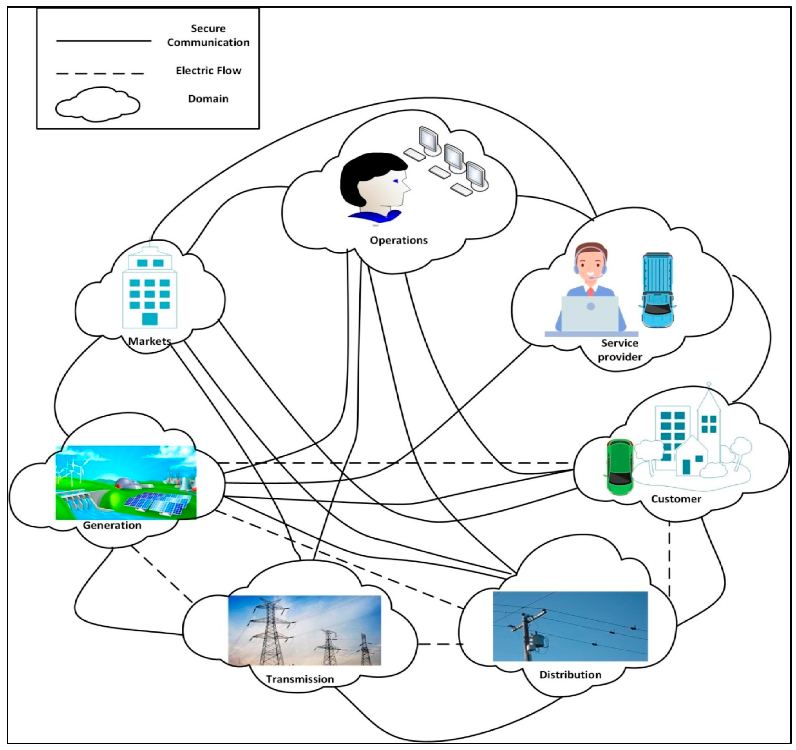
3. Problem Statement and System Model

Compared to the traditional grid, there are higher expectations with the smart grids to provide better services. Utility firms intend to convert the present unidirectional grid into a bi-directional power grid, with the goal of storing energy in the electrical system and using it wherever it is needed. Among other safety-critical applications, smart grids need precise modeling and the analysis of systems such as demand response, distribution automation, energy storage, and fault detection. These applications are critical because even a minor design flaw can have serious consequences, even at the expense of individual life and property. The present electricity grid is predicted to have expertise in the difficulties in the generation, transmission, and distribution of the requisite power for massive amounts of the demanding load. Considering the sophistication and complexity of today’s distribution networks, there is always the risk of underlying errors in models that are not detectable by evaluating a small number of scenarios. Network failures and high operating expenses might occur if these models fail. As a result, it appears that a mathematical model for distribution automation capabilities in smart grids that can be confirmed is required. The aim of this paper is to design a systematic model for a distribution management system comprised of substations, feeders, and smart meters. Modeling an IoT-based automated distribution management system will portray equipment utilization in substations, fault detection, and a recovery mechanism in transmission lines for the integrity and efficiency of the system.

3.1. Advanced Metering Infrastructure (AMI)

The primary objectives of the smart grid are: self-coordination, self-awareness, self-healing, and self-reconfiguration, to add intelligence to the grid so that it can perform, to increase the deployment of renewable energy sources, to improve the efficiency of power generation, transmission, and usage, and to shift and configure consumers’ energy demands by using demand response (DR) techniques to manage peak loads of customers. Sophisticated distribution automation and price optimization models based on automated meter reading (AMR) and advanced metering infrastructure are required to achieve this. Smart meters are similar to a traditional electric meter but with enhanced ICT-enabled features because they not solely measure the amount of energy consumed but also track a vast amount of data over time, such as the patterns of electricity usage. AMI uses smart control and communication technologies to automate metering services that were previously done by hand, which are time-consuming activities such as energy meter readings, service connection and disconnection, interventions and theft detection, the monitoring of voltage, and fault and outage identification, when combined with cutting-edge customer-centric technology. The Drive-by/Walk-by meter reading in AMI is depicted in Figure 2.
Figure 2. Drive-by/Walk-by automated meter reading.

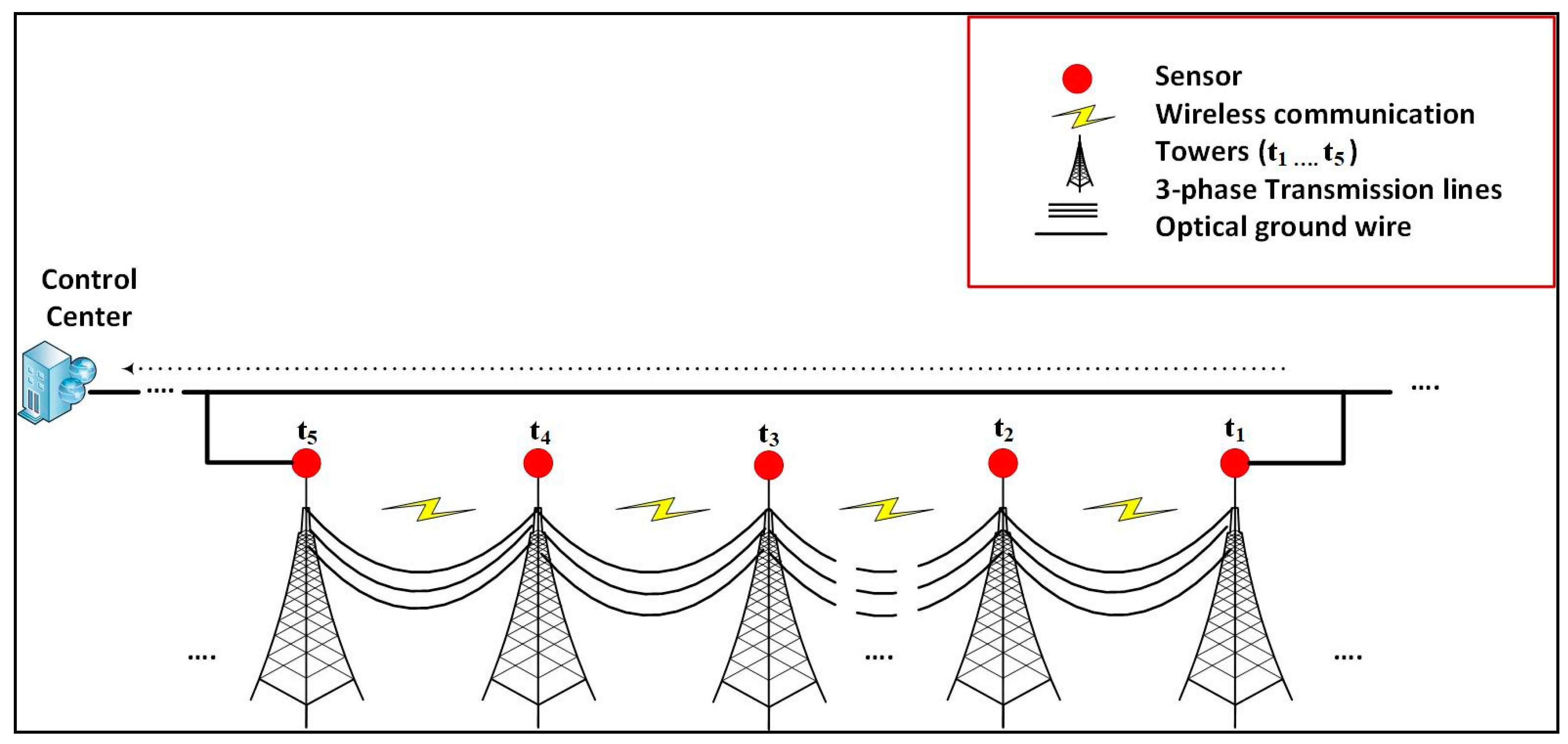
3.2. Cables and Transmission Lines

Power cables, including transmission and distribution-level lines, establish crucial links between the generation and load. These lines often transport low-voltage power that is stepped down from the transmission grid or generated by distributed generating systems. Transmission lines carry voltages from transmission to distribution points, whereas the distribution lines carry voltage from distribution to domestic use, such as to homes, offices, and buildings. The faults in the transmission lines network are classified into four categories [38], which are illustrated in Figure 3, with a brief explanation as follows.
Figure 3. Transmission line faults.
  • Single-line-to-ground fault
The most frequent transmission line fault is the single-line-to-ground (SLG) fault that might be caused by a vehicle accident, by tree branches, or by flashovers over dusty insulators during rain showers, which will cause one of the phase conductors to collapse and come in touch with the ground.
  • Line-to-line fault
When two phases of a three-phase line are unexpectedly coupled, a line-to-line fault occurs. The fault current will flow during both phases in this instance.
  • Double-line-to-ground fault
The two lines, as well as the ground, come in touch with each other in a double-line-to-ground fault. Such faults have a nearly 10% chance of occurring.
  • Triple-line-to-ground fault
A triple line-to-ground fault occurs when three lines come in touch with the neutral wire or lie on the ground.
In our proposed monitoring network of transmission lines, several wireless sensors are mounted on the chosen towers. The working principle of these sensors is to collect information about the operating conditions of the transmission lines as well as their surroundings. These sensors, after collecting data, send the data to the nearest IED through a communication gateway. Figure 4 shows the communication infrastructure between the sensors and IEDs. These IEDs will send the collected data to the control center. The important point to be considered here is that sensors do not need to be installed on all of the towers.
Figure 4. Transmission line monitoring.

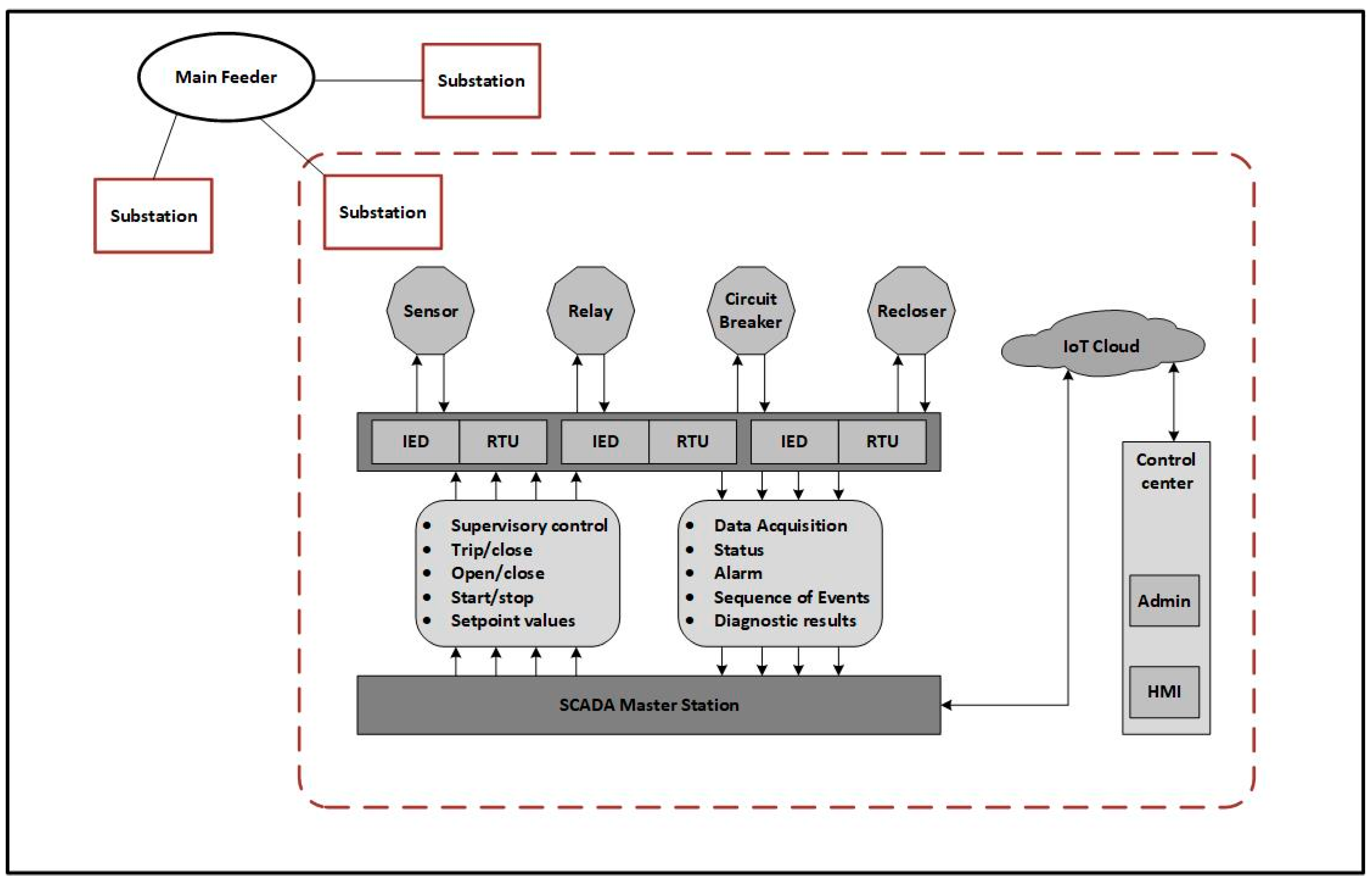
3.3. Intelligent Electronic Device (IED)

Intelligent electronic devices in the distribution network of smart grids play a crucial role. Whenever a fault is encountered because of the failure of the transformers or the line current surpasses the threshold value, the substation’s overcurrent relay trips the circuit breaker and the IED associated with that circuit breaker forwards an alarm message to other load-switch IEDs that are associated and operated by the IEDs of the substation’s circuit breaker. The relay will determine the fault as temporary or permanent if after one or two consecutive trippings of the circuit breaker, the system comes back to its previous state; that is, if the power supply is restored, the fault is considered temporary.
In the second scenario, after some consecutive tripping, if the system is unable to recover itself, the IEDs of the circuit breaker interact with the load switches of the IED to identify the actual fault location. After the fault identification, the fault localization will be finished when the load switch of the feeder terminal unit raises the fault flag; then, the next task of the IED is to isolate that area by tripping off the specific load switch. The load switch cuts off the power supply to the rest of the network within a short time span and transfers a message to each IED of the system components, including relays, circuit breakers, and tie switches, for the purpose of power supply restoration in the substation’s faulty area. If the non-active switch is unable to restore the substation’s power supply through the primary source, then it will choose another fault-free energy side. Figure 5 shows the possible states of the IED in the substation.
Figure 5. Possible states of the IED during the fault.

3.4. Supervisory Control and Data Acquisition (SCADA) System

A smart grid is made up of several micro subsystems that work together to share connectivity and security components. It is the core component of the substation’s control center, which is not only a monitoring system but also provides communication links. It is used for automating the distribution network of a medium voltage substation for intelligent remote controlling. This controlling and monitoring infrastructure provides benefits to the power utilities by enhancing electric supply maintainability and lowering the cost of operation [10]. The essential features of SCADA are gathering data, presentation and monitoring, supervisory control, and notifying alarms as shown in Figure 6. It includes both hardware and software, having primary components such as human–machine interfaces (HMIs), programmable logic controllers (PLCs), data collection servers, and remote terminal units (RTUs).
Figure 6. IoT-based SCADA communication in a substation.

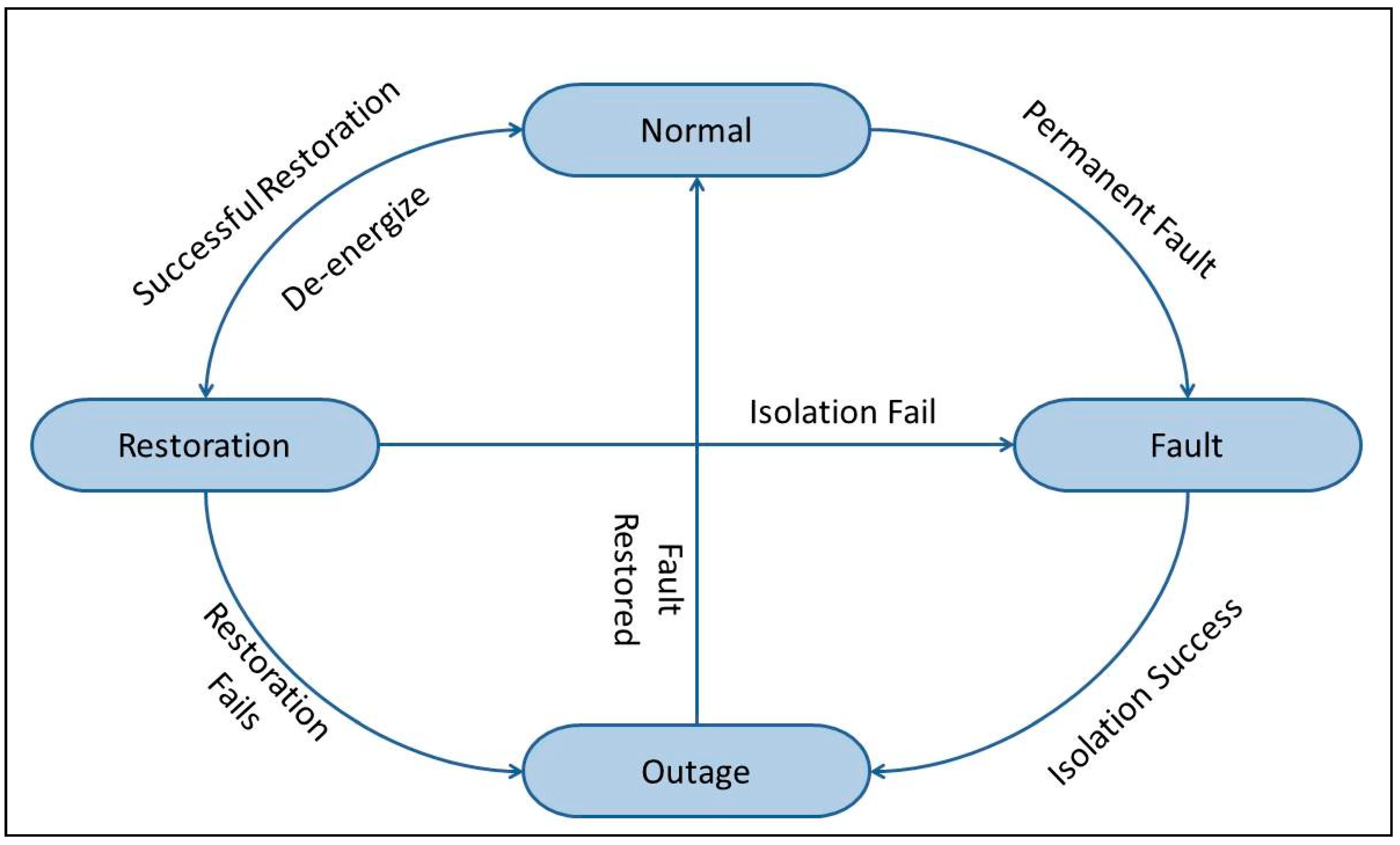
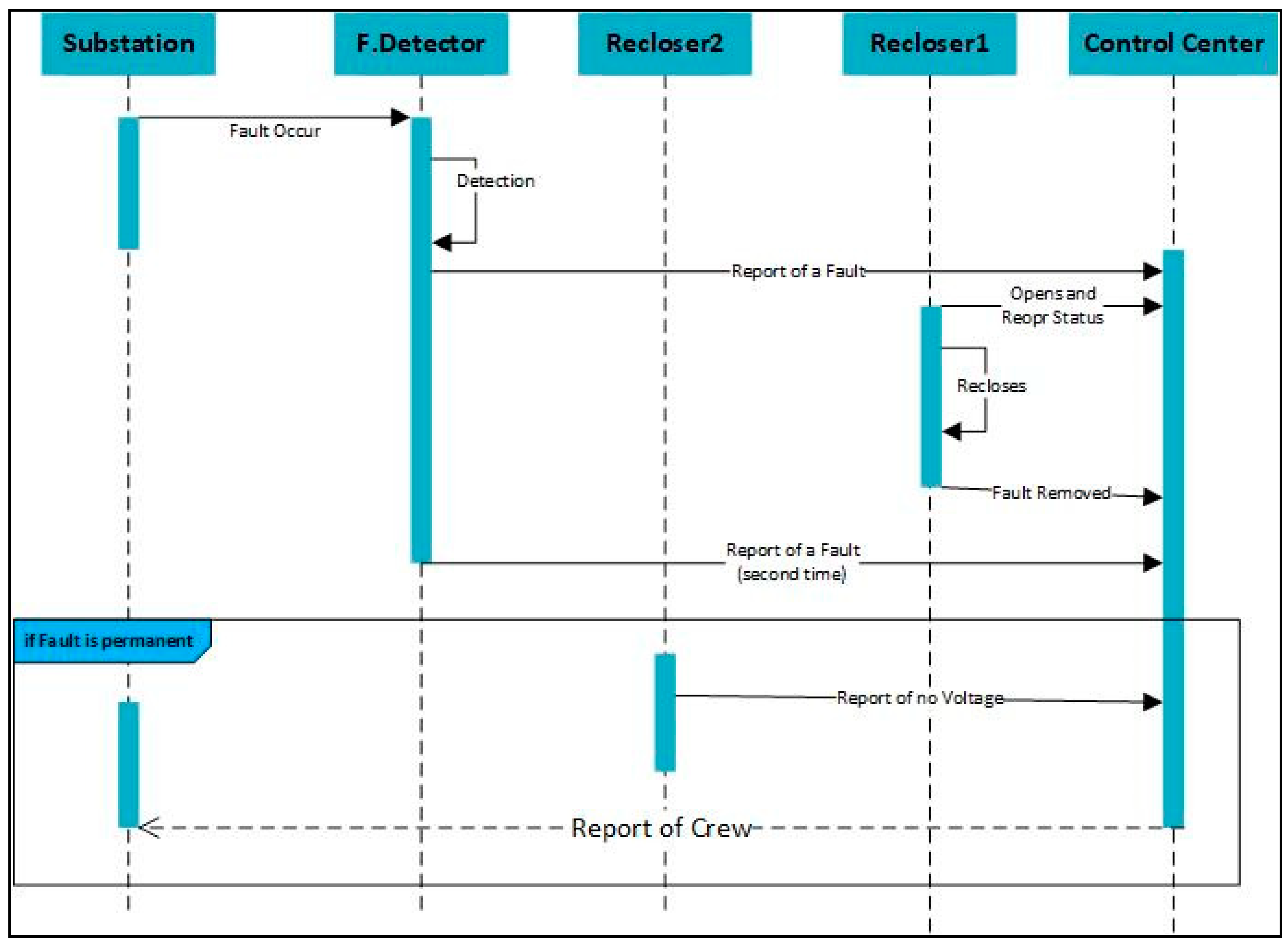
3.5. Sequence Diagram

The Unified Modeling Language (UML) is a software engineering modeling language that tries to standardize how to depict a system’s architecture [39]. UML is used to create a variety of diagrams, including interface, structural, and behavior diagrams. The most frequent type of interaction diagram is a sequence diagram. A sequence diagram simply displays the order in which objects interact or the order in which these interactions occur. Sequence diagrams show how and in what sequence the components of a system work together. In Figure 7, the sequence diagram of fault detection is shown, such as, whenever a fault occurs in the substation, the detector will eventually detect the fault and send a report message to the control center and the nearest recloser will automatically open itself according to the predefined instructions embedded in it. After the first tripping, the connected circuit breaker will try to make contact, and if the recloser recloses itself, the connection will be reestablished, the fault will be recorded as temporary, and then no further actions will need to be performed.
Figure 7. UML sequence diagram of fault detection in a substation.

4. Formal Model

Formal methods are mathematical entities that are used to model complicated systems. It is feasible to validate the characteristics of a complex system in a more formalized manner than empirical testing by developing a mathematically rigorous model of the system. Formal specifications are the descriptions of a model that can be described in a thorough and consistent manner for an application domain, a requirement or a group of requirements, software architecture, or program organization [40]. Formal methods in terms of the Vienna Development Method-Specification Language (VDM-SL) are used for the description and formal modeling of the system in a systematic way. Various constructs, such as composite objects, invariants, sets and pre/post-conditions, are used for developing the specifications.

4.1. Static Model

Formal methods are mathematical entities that are used to model complicated systems. It is feasible to validate the characteristics of a complex system in a more formalized manner than empirical testing by developing a mathematically rigorous model of the system. Formal specifications are the descriptions of a model that can be described in a thorough and consistent manner for an application domain, a requirement or a group of requirements, software architecture, or program organization [41]. The proposed model in this article signifies yet another contribution in this field. In programming languages, composite types are equivalent to record types. The static components include invariants for integrity checking of the condition, which must always hold true, and the fields, in the case of composite objects, may have several data types. In the formal specifications of the distribution system, one portion includes the data types of the variables, alongside which their quote types are declared. The model is comprised of various variables such as sequence type, token type, and string type. To record everything in the system, the date and time are taken as composite objects.
types
LID = token;
DID = token;
SID = token;
SBID = token;
TID = token;
Details = token;
Wire = token;
String = seq of char;
CName =String;
CID=token;
MID = token;
Relay = token;
Ack = <yes>|<no>;
Mode = <idle>|<working>|<damage>;
Status = <ON>|<OFF>;
Signal = <OPEN_Recloser>|<CLOSE_Recloser>|<DO_Nothing>|<Restored>;
FType = <Temporary>|<Permanent>;
FAlert = <Detected>|<NoDetected>;
FInfo = <Transmitted>|<Received>;
Fcat = <LL>|<LG>|<LLG>|<LLL>;
Date::   day: nat
        Month:nat
     Year:nat;
Time:: hour:nat
       min:nat
inv mk_Time(hour,min) == hour < 24 and min < 60;
The composite object substation consists of the substation ID; the capacity of the substation means the total amount of electricity to send and receive, the details about the substation, and the set of transformers. The invariant on the composite object substation is defined, and it ensures that the capacity of the substation will always be more than 0.
Substation :: id : SBID
      capacity : real
      details : Details
      transformers : set of Transformer
inv mk_Substation(-,c,-,-) == c > 0;
The next composite object is the transformer, which has five fields: transformer ID; its mode, with three possible conditions idle|working|damage; location of the transformer; and the capacity of carrying voltage, respectively.
Transformer :: tid:TID
         mode:Mode
         location : String
         tcapacity : real
         date : Date;
The third composite object transmission line is composed of the line ID; a detector, which is embedded on each transmission line; the phase voltage of type real value; and the zero sequence current of type real. The zero sequence current is the unbalance flow of the current during the earth fault. Three lines are taken as wire, and the invariant on these lines ensures that all these lines are distinct from each other.
Transmissionline :: lineid : LID
         detector : Detector
         phasevoltage : real
         zeroscurrent: real
         line1 : Wire
         line2 : Wire
         line3 : Wire
    inv mk_Transmissionline(-,-,-,-, l1, l2, l3) == (l1<>l2 and l1<>l3 and l2 <>l3);
The detector is the one that is embedded in each transmission line and the near-to-field devices, such as transformers and meters, and in the substation area. Each detector is distinguished based on the unique ID. The possible values of the detector status would be on and off. The purpose of the detector is to determine the type of the fault, whether it is temporary or permanent, and if the fault is permanent, it will further inform about the category of the fault, whether it is <LL> line-to-line fault, <LG> line-to-ground fault, <LLG> double line-to-ground fault, or <LLL> line-line-line fault. To keep the database of faults updated, it is necessary to add the date and time of the fault.
Detector :: id : DID
   status : Status
   ftype: FType
   fcat:Fcat
     signal : Signal
         fdate : Date
           ftime : Time;
The composite object Voltsensor is created for the sensor, which is used for measuring the voltage of the power. The deviation in the nominal values of voltage and current causes most electrical faults, so it is most important to continuously measure the value of the voltage in the lines. Actual load and requested load are those values of the voltage that are actually flowing and demanding, respectively. The sensor will send the alert message to the control center and provide the fault info.
Voltsensor ::   vsid: SID
           volt:real
           nvolt:real
                actualload : int
                requestedload : int
           faultalert: FAlert
           faultinfo: FInfo;
The keyword values is used to specify the constants of the specifications in VDM-SL. This declaration of values comes right before the state definition. Here, we declare the phase voltage and zero sequence current values. These values will be used in the fault detection operation. These values are specified here for the efficient working of the system. If the threshold values are exceeded, the system will go into the imbalance condition, which is the faulty state.
Values
phasevoltage = 160;
zeroscurrent = 35;
Limit = 200;

4.2. Dynamic Model

The dynamic components include the state definition, the possible operations, and the reusable functions. Various constructs, such as composite objects, invariants, sets, and pre/post conditions, are used for developing the specifications. IoT is deployed in the smart grid for detecting the faults that consist of sensors and detectors. The exceptional part of the VDM-SL specification is state, in which the variables are declared in a similar manner as in the other programming languages. The attribute specified in the state is permanently stored by the system. The illustration/explanation of specifying the state for our DMS is as follows. Many variables have been declared, with their data types being used in the state. Invariants are defined in these variables, which must be true for the system from the beginning to the system termination. The state of the system is always finished with the keyword end.
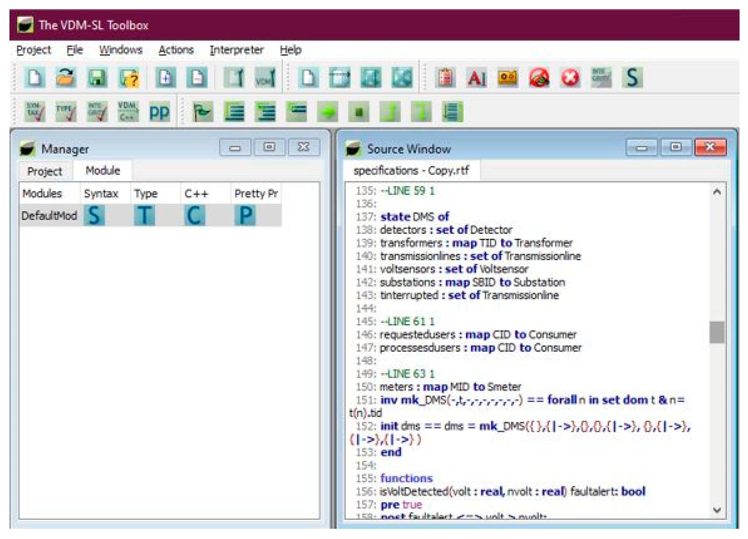
state DMS of
detectors : set of Detector
transformers : map TID to Transformer
transmissionlines : set of Transmissionline
voltsensors : set of Voltsensor
substations : map SBID to Substation
tinterrupted : set of Transmissionline
requestedusers : map CID to Consumer
processesdusers : map CID to Consumer
meters : map MID to Smeter
inv mk_DMS(-,t,-,-,-,-,-,-,-) == forall n in set dom t & n = t(n).tid
init dms == dms = mk_DMS({ },{|->},{},{},{|->}, {},{|->},{|->},{|->} )
end
The function is another tool that is vital when specifying complicated systems. These functions can be used later in operations. The following function is defined to check the voltage: nvolt is the normal voltage, and volt is the abrupt change in the voltage if it becomes high. We will use this function later in our operation of fault detection.
Functions
isVoltDetected(volt : real, nvolt : real) faultalert: bool
pre true
post faultalert <=> volt > nvolt;
The dynamic behavior of the system is described by exploiting operations. A non-mandatory pre-condition and a mandatory post-condition are required to represent the operation. By specifying the pre-conditions, each operation is correlated to the preceding one. Post-conditions are used to specify the accuracy of an operation. Our proposed formal model performs various operations on the distribution management system, such as checking the capacity of the substation to get its details and adding transformers to the substation.
Operations
The operation check capacity is designed to measure the total capacity of any specific substation in the smart grid. The capacity refers to the capability of power storage and power transfer to the distribution transformers. It takes one input, which is the ID of the specific substation, and will return the value of the capacity in the real data type. Before proceeding to the post-condition, the system will ensure the pre-condition. In the external clause, the rd keyword is used to tell the system that the access type is only to read.
checkCapacity(idIn: SBID) cap : real
ext rd substations : map SBID to Substation
pre idIn in set dom substations
post cap = (substations(idIn)).capacity;
Pre-conditions (1) The registration of the specific substation is the first check by the system that the given ID is in the mapping of the substation in the system record.
Post-conditions (1) The mapping of the substations is applied to the entered ID of the substation, which will create an object; the dot operator is used with the capacity attribute, which will take the value of the specified entry and return it as a real number. The get details operation is defined for getting the details of the specific substation. This operation is useful for obtaining the overall detail of the substation at any time; the system is updated periodically.
getDetails(idIn: SBID) detailsOut : Details
ext rd substations : map SBID to Substation
pre idIn in set dom substations
post detailsOut = (substations(idIn)).details;
Pre-conditions The registration of the specific substation is the first check by the system that the given ID is in the mapping of the substation in the system record.
Post-conditions The mapping of the substations is applied on the entered ID of the substation, which will create an object, and, with the dot operator, it will take the value of the specified entry and return the appropriate fields of details for that particular substation. When the demand for electricity usage increases, the need will be to receive more power from generation resources so that the demand of the consumers is met. The extra received electricity needs to be stored in the main substation, which means the need will arise for new substation transformers of heavy capacity. The add transformer SB refers to the newly added transformer in the substation. The required fields for the new record are: the substation ID in which it is being deployed and recorded, transformer ID, capacity of the new transformer, its location, and the date on which the transformer was added into the system. The external clause is used to give the write access to the mapping of substations.
addTransformerSB (idIn : SBID, tidIn : TID, tcapacityIn : real, locationIn:String, dateIn:Date)
ext wr substations : map SBID to Substation
pre idIn not in set dom substations
post let trans = (substations~(idIn)).transformers
       in let newTrans = mk_Transformer(tidIn, <idle>, locationIn, tcapacityIn,
dateIn)
      in substations = substations~ ++ {idIn |-> mu (substations~ (idIn), transformers
|-> trans union {newTrans})};
Pre-conditions (1) The registration of the specific substation is the first check by the system that the given ID is not in the mapping of the substation in which the transformer is added.
Post-conditions (1) The let-in clause is used here to overcome the complexity of the operation. More than one let-in clause can be used in a single operation, such as in the post-condition. (2) Here, two local names ‘trans’ and ‘newTrans’ are used for the sub-expressions (substations~(idIn)).transformers and mk_Transformer (tidIn, <idle>, locationIn, tcapacityIn, dateIn), respectively. (3) Both of these local names are joined in the last sub-expression, with the union operation to add a new record in the substations mapping. The following operations are defined for the entity transformer. The add transformer operation is for the new transformer that is being deployed into the distribution network for the electric supply to the user. The required fields are the ID, location, and date of entry.
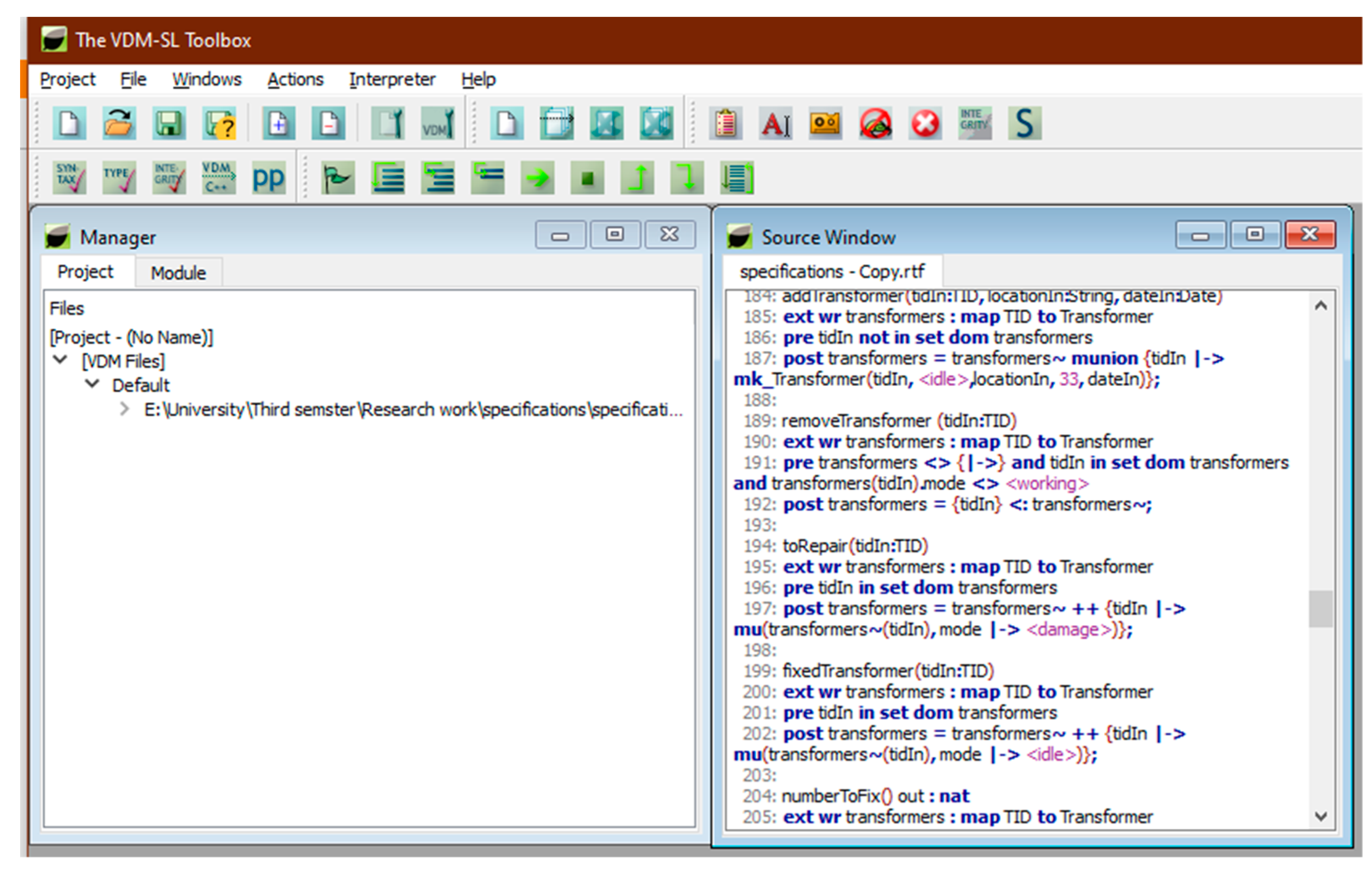
addTransformer(tidIn:TID, locationIn:String, dateIn:Date)
ext wr transformers : map TID to Transformer
pre tidIn not in set dom transformers
post transformers = transformers~ munion {tidIn |-> mk_Transformer(tidIn, <idle>, locationIn, 33, dateIn)};
Pre-conditions (1) The pre-condition is to first check the transformers mapping to ensure that there is no already existing transformer with the same ID.
Post-conditions (1) The post-condition accepts the ID of a new transformer and records the fact that this transformer has been added with the specified fields to the collection of transformers.
The operation removeTransformer is similar to the addTransformer operation in nature except the fact that its pre-condition is different; it accepts the ID of a transformer and records the removal of this transformer from the system.
removeTransformer (tidIn:TID)
ext wr transformers : map TID to Transformer
pre transformers <> {|->} and tidIn in set dom transformers and transformers(tidIn).mode <> <working>
post transformers = {tidIn} <: transformers~;
Pre-conditions (1) The pre-condition is to first check the transformers mapping to ensure that the accessed mapping is not empty; in brief context, in order to remove a record from the system, there should a record present in it. (2) The specified ID to be removed is in the collection of transformers. (3) The working mode of the transformer is checked, in that its status should not be working, which means its status can be any other than working.
Post-conditions (1) The post-condition accepts the ID of a new transformer and removes the required transformer from the collection of transformers.
To record a transformer as damaged, the operation to repair accepts the ID of a transformer and records its mode as damaged. To change the records of the composite object, the write access is given to the transformers mapping with the external clause.
toRepair(tidIn:TID)
ext wr transformers : map TID to Transformer
pre tidIn in set dom transformers
post transformers = transformers~ ++ {tidIn |-> mu(transformers~(tidIn), mode |-> <damage>)};
Pre-conditions (1) The pre-condition is to first check the transformers mapping to ensure that the transformer is in the collection of transformers.
Post-conditions (1) The post-condition accepts the ID of the transformer, and, by using the override, the operator changes the required fields of that transformer, and then the collection of transformers will be updated.
To update the record of the transformer’s collection, the operation fixedTransformer accepts the name of a damaged transformer and records that its mode is set to idle; the other process is the same as above.
fixedTransformer(tidIn:TID)
ext wr transformers : map TID to Transformer
pre tidIn in set dom transformers
post transformers = transformers~ ++ {tidIn |-> mu(transformers~(tidIn), mode |-> <idle>)};
The operation numberToFix returns the number of total damaged transformers. The operation will return a natural number value.
numberToFix() out : nat
ext wr transformers : map TID to Transformer
pre true
post out = card {t | t in set rng transformers & t.mode = <damage>};
Pre-conditions (1) The pre-condition is true here, which refers to the condition that there is no need to apply any check or constraints because, without any pre-condition, the post-condition will work perfectly, such that it is just a read type operation.
Post-conditions (1) The cardinality operator is used here to take the number from a set type. (2) The condition in braces checks that there exists a transformer in the range of the transformers mapping of them; if the mode is damaged, then the total gathered transformers will be returned as a number.
To determine the total number of transformers under a substation, we created the operation of get_total_Transformer, which will return a natural number value.
get_total_Transformer()out:nat
ext rd substations : map SBID to Substation
pre true
post out = card dom substations;
The important aspect of the distribution management system is to detect the theft ofequipment in the substation. It can be ensured by checking the supply or working mode of the transformer; the operation will take the ID of the transformer as input and the query will return as true or false, depending on the post-condition check.
detectTransformerTheft(tidIn:TID) query : bool
ext wr transformers : map TID to Transformer
pre true
post query <=> tidIn in set dom transformers and transformers(tidIn).mode <>
<working>;
Post-conditions (1) The query will return as true when the specified transformer is in the record of the substation but the system shows its mode is not working. (2) We ensure that we have already created an operation of damaged transformers, so it cannot be considered that if a transformer is not working, it is in the damaged transformer collection. (3) The damaged transformer records are updated with the time, so a nonworking transformer will be considered as lost.
To detect the fault in the transmission line, a volt measuring sensor is taken as input in the following operation; it will return a Boolean type value in the form of true/false.
faultDetection(voltsensorIn : Voltsensor) faultalert: bool
ext rd voltsensors : set of Voltsensor
pre voltsensorIn in set voltsensors
post faultalert <=> voltsensorIn.volt > voltsensorIn.nvolt and
voltsensorIn.faultinfo=<Transmitted>;
Pre-conditions (1) The pre-condition will check the fact that the voltage measuring sensor is in the collection of Voltsensor.
Post-conditions (1) Fault alert will return true only if the volt value is greater than the normal volt that is nvolt; the fault info is transmitted to the control center. The major task of the distribution management system is to categorize the type of fault. Our operation determines that the fault type is quite lengthy yet easy to understand. The operation takes three transmission lines as input and the detector. The specified fields for fault detection in transmission lines are three transmission lines and one detector mounted on the tower. Read and write access is given to the collection of transmission lines, detectors, and the set of interrupted lines.
determineFaultType (lineIn1 : Transmissionline, lineIn2 : Transmissionline, lineIn3 : Transmissionline, detectorIn : Detector) signal : Signal
ext rd transmissionlines : set of Transmissionline
      rd detectors : set of Detector
      wr tinterrupted : set of Transmissionline

pre lineIn1 in set transmissionlines and lineIn2 in set transmissionlines and lineIn3 in
set transmissionlines and detectorIn in set detectors and detectorIn.status=<ON> and
tinterrupted = {}
post if lineIn1.phasevoltage > 160 and lineIn2.phasevoltage > 160 then tinterrupted
<>{}and detectorIn.ftype = <Permanent> and detectorIn.fcat= <LL> and signal =
<OPEN_Recloser>
elseif lineIn2.phasevoltage > 160 and lineIn3.phasevoltage > 160 then tinterrupted
<>{}and detectorIn.ftype = <Permanent> and detectorIn.fcat= <LL> and signal =
<OPEN_Recloser>
elseif lineIn1.phasevoltage > 160 and lineIn1.zeroscurrent > 35 then tinterrupted <>{}and
detectorIn.ftype = <Permanent> and detectorIn.fcat= <LG> and signal =
<OPEN_Recloser>
elseif lineIn2.phasevoltage > 160 and lineIn2.zeroscurrent > 35 then tinterrupted <>{}and detectorIn.ftype = <Permanent> and detectorIn.fcat= <LG> and signal =
<OPEN_Recloser>
elseif lineIn3.phasevoltage > 160 and lineIn3.zeroscurrent > 35 then tinterrupted <>{}and detectorIn.ftype = <Permanent> and detectorIn.fcat= <LG> and signal =
<OPEN_Recloser>
else signal =<DO_Nothing>;

Pre-conditions (1) The pre-condition will check the fact that the transmission lines are in the set of transmission lines. (2) The status of the detector is working. (3) Initially, there is no pending fault such that the set of interrupted transmission lines is empty.
Post-conditions (1) Two types of faults are detected in the post-condition by comparing the combinations of transmission lines. (2) Two constraints, phase voltage and zero sequence current, are used here for checking the proper working condition of the lines. (3) For any combination of two adjacent wires, if these constraints exceed the threshold value, the fault will occur and will be detected by the detector, which will determine the fault type as permanent and send a signal to the nearest recloser to open itself. (4) When two adjacent wires exceed the value of phase voltage, they will touch each other and the occurring fault will be a line-to-line fault. (5) If one of the three wires exceeds the phase voltage as well as the zero sequence current value, the occurring fault will be considered a line-to-ground fault. The following function takes the transformer ID as input and will send a signal to the control center about the restoration of the supply. In the post-condition, the mode is checked for that specific transformer if the result is true; if it is in the condition, then a restored signal is sent to the system; in the opposite case, it sends a signal to do nothing.
serviceRestore(tidIn: TID) signal : Signal
ext rd transformers : map TID to Transformer
pre tidIn in set dom transformers
post if transformers(tidIn).mode= <working> then signal = <Restored> else signal = <DO_Nothing>;
Pre-conditions (1) The pre-condition is to first check whether the given ID is in the collection of transformers.
Post-conditions (1) The specified transformer mode is checked as to whether it is working or not. If the mode is equal to working, then a signal will be transferred to the control center that the service has been restored.
The following operations are specified for the transmission lines. For checking the specific line against an ID, the first operation is used, which will check that line in the interrupted collection of wires. After resolving the fault of the specific line, it will add up to the collection of transmission lines; transmissionlines~ is the old set of transmission lines and transmissionlines is the updated collection. To remove a faulty line from the interrupted transmission line collection, write access is used here to change the record. Sometimes, the continuous flow of the current in the wires gets changed due to some inner or outer conditions of the system, and the system starts tripping; this tripping mostly happens in the nearest circuit breaker.
lineRestore(lineidIn:LID)
ext wr transmissionlines : set of Transmissionline
pre true
post transmissionlines = transmissionlines~ union {lineidIn};

removeFaultyLine()
ext wr tinterrupted : set of Transmissionline
pre tinterrupted <> {}
post tinterrupted = {};

tripCB(voltsensorIn : Voltsensor) trip: bool
ext rd voltsensors : set of Voltsensor
pre true
post trip <=> voltsensorIn.requestedload > voltsensorIn.actualload;

The following are the smart meters’ operations: initially, the consumers request that the smart meter be installed at their residence; the required attributes are taken as input, which is stored in the system for further use in the future. The smart meter installation takes the required data of the user as input and also the unique ID of the meter that is being installed. The last two operations are regarding the usage of the units and meter removal.
requestMeter(cidIn : CID,cnameIn: CName, dateIn: Date, detailsIn: Details)
ext wr requestedusers: map CID to Consumer
rd processesdusers : map CID to Consumer
pre cidIn not in set dom requestedusers
post requestedusers = requestedusers~ munion {cidIn |->mk_Consumer(cidIn, cnameIn,
dateIn, detailsIn)};
Pre-conditions (1) The pre-condition is to first check that the request has not already been registered against the ID of the consumer.
Post-conditions (1) The post-condition is updating the mapping of the requested user. The installMeter operation will record the fact that the request of the specified consumer is completed with the complete details of the consumer and that the date of the record is also updated.
installMeter(cidIn : CID, cnameIn: CName, dateIn: Date, detailsIn: Details, midIn: MID)ack : Ack
ext wr processesdusers : map CID to Consumer
wr meters : map MID to Smeter
rd requestedusers : map CID to Consumer
pre cidIn in set dom requestedusers and midIn not in set dom meters
post meters= meters~ munion {midIn |-> mk_Smeter(midIn,2000)}
      and processesdusers= processesdusers~ munion {cidIn |-> mk_Consumer(cidIn, cnameIn, dateIn, detailsIn)}and ack = <yes>;
Pre-conditions (1) The pre-condition is to first check that the request is not yet processed and the meter ID is not in the already installed meter collection.
Post-conditions (1) The post-condition is updating the mapping of the meters; the requested user is added to the processed users, and an acknowledge message is sent to the system that a new meter has been installed and the request has been processed.
To limit the usage of the electricity unit, the load limit operation is specified here, in which the pre-condition ensures that the meter is in the collection of meters and the usage limit is crossing or exceeding the specified value. In the post-condition, the status of the meter load limit will be enabled.
loadLimit(midIn: MID)
ext wr meters: map MID to Smeter
pre midIn in set dom meters and meters(midIn).munits > Limit
post meters = meters~ ++{ midIn|-> mu (meters~(midIn), status|->
<Enable>)};
The removeMeter operation illustrates the procedure of removing a meter that has crossed the limit of the given units and has not yet paid for the previous transaction.
removeMeter(midIn: MID)
ext wr meters : map MID to Smeter
pre midIn in set dom meters and meters(midIn).munits > Limit
post meters = {midIn} <: meters~ ;

5. Model Analysis

To analyze and verify formal specifications, the VDM-SL toolbox was deployed through the exploitation of its prevailing service. The toolbox comprises various services for ensuring accuracy, such as syntax and type checking, pretty printer, C++ code generation, interpreter, integrity inspector, dynamic verification, and several other validations and analysis techniques. No tool exists to provide a complete guarantee of the absolute correctness of any system model. Therefore, the formal specification does not assure that system is completely accurate. However, it helps in the identification of the possible errors at the initial stages of any software development. The design and analysis of the model help to recognize areas of ambiguity and incompleteness in the requirements of the informal framework and give a degree of assurance that the key properties, in particular those of safety or security, will be appropriate for legitimate implementation. The specifications of the system are analyzed through the VDM-SL toolbox. The specification is evaluated via syntax, type checker, generator of C++ code, and pretty printer. In the formal specification, the reported errors are eliminated earlier by enhancing the characteristics of invariants and pre/post-conditions as well. The developed formal specification is approved with success through all checkers, and the proof of correctness is shown in Figure 8.
Figure 8. Proof of correctness.
An integrity analyzer is used to determine the specification’s integrity properties. The dynamic level of the requirements is examined by the integrity checker, and VDM-SL predicates are defined by a set of formulated integrity properties that specify the parameters in which no runtime error should execute. There will be no runtime error if the integrity property responds to true. All integrity properties are found to verify the true condition of the specification. For the validation of model properties, invariants and pre/post-conditions are specified.
There are two functions that are necessary to be performed in order to ensure the system’s formal validation’s validity. The VDM-SL toolbox provides syntax and type checkers that evaluate the developed static and dynamic models. Initially, there were numerous syntax and type errors within the model specification, which were explored by the tool’s syntax and semantics evaluation as shown in Figure 9.
Figure 9. Model analysis.
The detailed description of the proposed model is defined in tabular form, as given in Table 2 and Table 3.
Table 2. Formal analysis of the transformer module.
Table 3. Formal analysis of the fault detection module.

6. Conclusions

The smart grid is an excellent innovation of engineering and technology for the modern world. There are numerous studies concerning the distribution layer of the smart grid, but this is majorly concentrated on the modeling of the distribution management system because very little work has been done in this domain. The obligation is to utilize the current state-of-the-art technologies in better sensing, detecting, communicating, and controlling the grid, especially the distribution network layer, to make the grid robust, efficient, and resilient. In this article, we present the formal model of an automated distribution management system for smart grids. The aspiration of using formal methods in smart grids is to design a formalized model in an efficient way so that there is less chance of errors during the implementation because smart grids are a safety-critical domain, where a minor error can lead to severe destruction to equipment or serious harm to humans. An IoT-based automated distribution management system is introduced in the form of formal specifications. The system helps to ensure the correct and cost-effective functioning of the system at the user end as well as service-provider end because the designed system has been produced for substation automation; transmission line fault detection and its restoration; components management, such as transformers; and the specifications of smart meters, enabling the properties of advanced metering infrastructure. The absolute necessity of employing formal techniques in safety-critical systems leads to the suggested system’s precision, consistency, and correctness. To demonstrate and justify the formal specification’s validity, the Vienna Development Method-Specification Language (VDM-SL) was deployed. The formulated specification of the IoT-based formal model of a distribution management system was then substantiated and analyzed by employing the VDM-SL toolbox facilities. The reported errors were eliminated earlier by enhancing the characteristics of invariants and pre/post-conditions. Moreover, examining specifications and implementing them by utilizing comprehensive computer tools enhances reliability through the exploration of possible problems in the initial phases of the development of system design. We would like to point out here that the framework recently proposed here presents only a few distribution level components. However, the same principle may be used for a wide range of components of each layer of the smart grid as future prospects; additionally, we will employ model checking and simulation approaches to extend our work to real-world scenarios.

Author Contributions

Conceptualization, S.K. and N.A.Z.; Introduction, S.K., T.A., N.A.Z. and E.H.A.; Background. N.A.Z., T.A. and E.H.A.; Contribution, S.K., N.A.Z., T.A. and E.H.A.; Related work, S.K., N.A.Z., T.A. and E.H.A.; System Architecture S.K., M.H. and N.A.Z.; Introduction to Formal Modeling, S.K., N.A.Z., T.A., M.H. and E.H.A.; Formal specification, S.K. and N.A.Z.; Formal Analysis, S.K., N.A.Z., T.A., M.H. and E.H.A. All authors have read and agreed to the published version of the manuscript.

Funding

This work is supported by the Taif University Researchers Supporting Project (number TURSP-2020/292), Taif University, Taif, Saudi Arabia. This work is also supported by the Princess Nourah bint Abdulrahman University Researchers Supporting Project (number PNURSP2022R193), Princess Nourah bint Abdulrahman University, Riyadh, Saudi Arabia.

Institutional Review Board Statement

Not applicable.

Data Availability Statement

Not applicable.

Acknowledgments

The authors would like to acknowledge the Taif University Researchers Supporting Project number (TURSP-2020/292), Taif University, Taif, Saudi Arabia. The authors would also like to acknowledge the Princess Nourah bint Abdulrahman University Researchers Supporting Project number (PNURSP2022R193), Princess Nourah bint Abdulrahman University, Riyadh, Saudi Arabia.

Conflicts of Interest

The authors declare no conflict of interest.

References

  1. Aderibole, A.; Aljarwan, A.; Rehman, M.H.U.; Zeineldin, H.H.; Mezher, T.; Salah, K.; Damiani, E.; Svetinovic, D. Blockchain technology for smart grids: Decentralized NIST conceptual model. IEEE Access 2020, 8, 43177–43190. [Google Scholar]
  2. Abadi, S.R.; Mahmoodi, M.; Fereidunian, A.; Jahandoust, G.; Leasni, H. Formal verification of fault location, isolation and service restoration in distribution automation using UPPAAL. In Proceedings of the 2017 Conference on Electrical Power Distribution Networks Conference (EPDC), Semnan, Iran, 19–20 April 2017; pp. 96–100. [Google Scholar]
  3. Spalding, R.A.; Rosa, L.H.; Almeida, C.F.; Morais, R.F.; Gouvea, M.R.; Kagan, N.; Mollica, D.; Dominice, A.; Zamboni, L.; Batista, G.H.; et al. Fault Location, Isolation and service restoration (FLISR) functionalities tests in a Smart Grids laboratory for evaluation of the quality of service. In Proceedings of the 2016 17th International Conference on Harmonics and Quality of Power (ICHQP), Belo Horizonte, Brazil, 16–19 October 2016; pp. 879–884. [Google Scholar]
  4. Chishti, S.O.A.; Naseem, S.A.; Uddin, R.; Saleem, M.H.; Naseem, S.W. Intelligent Control System to Identify Fault in Distribution Network of Smart Grid through Neural Network. In Proceedings of the 2019 4th International Electrical Engineering Conference (IEEC 2019), IEP Centre, Karachi, Pakistan, 25–26 January 2019. [Google Scholar]
  5. Rajpoot, S.C.; Rajpoot, P.S.; Khan, M. Electricity Pilferage, Fault Detection and their Isolation for Power Quality enhancement in Electrical Distribution System by espouse SDS with Smart Switching Control based on μ PMU, IoT-LoRa technology. In Proceedings of the 2020 International Conference on Communication and Signal Processing (ICCSP), Chennai, India, 28 July 2020; pp. 307–314. [Google Scholar]
  6. Khan, F.; Siddiqui, M.A.B.; Rehman, A.U.; Khan, J.; Asad, M.T.S.A.; Asad, A. IoT based power monitoring system for smart grid applications. In Proceedings of the 2020 International Conference on Engineering and Emerging Technologies (ICEET), Lahore, Pakistan, 22–23 February 2020; pp. 1–5. [Google Scholar]
  7. Patil, S.; Zhabelova, G.; Vyatkin, V.; McMillin, B. Towards formal verification of smart grid distributed intelligence: Freedm case. In Proceedings of the IECON 2015-41st Annual Conference of the IEEE Industrial Electronics Society, Yokohama, Japan, 9–12 November 2015; pp. 3974–3979. [Google Scholar]
  8. Dhend, M.H.; Chile, R.H. Innovative scheme for smart grid distribution SCADA system. In Proceedings of the 2015 IEEE 2nd International Future Energy Electronics Conference (IFEEC), Taipei, Taiwan, 1–4 November 2015; pp. 1–6. [Google Scholar]
  9. Akram, W.; Niazi, M.A. A formal specification framework for smart grid components. Complex Adapt. Syst. Modeling 2018, 6, 5. [Google Scholar]
  10. Goel, N.; Agarwal, M. Smart grid networks: A state of the art review. In Proceedings of the 2015 international conference on signal processing and communication (ICSC), Noida, India, 16–18 March 2015; pp. 122–126. [Google Scholar]
  11. Divyapradeepa, T. Fault diagnosis on distribution system using PLC & SCADA. Int. J. Innov. Res. Sci. Eng. Technol 2017, 6, 21393–21401. [Google Scholar]
  12. Chen, J. Research on power system automation communication technology for smart grid. In IOP Conference Series: Materials Science and Engineering; IOP Publishing: Bristol, UK, 2019; Volume 569, p. 042025. [Google Scholar]
  13. Alhelou, H.H.; Golshan, M.H.; Askari-Marnani, J. Robust sensor fault detection and isolation scheme for interconnected smart power systems in presence of RER and EVs using unknown input observer. Int. J. Electr. Power Energy Syst. 2018, 99, 682–694. [Google Scholar]
  14. Ferreira, E.F.; Barros, J.D. Faults Monitoring System in the Electric Power Grid with Scalability to Detect Natural/Environmental Catastrophes. Int. J. Therm. Environ. Eng. 2018, 16, 37–45. [Google Scholar]
  15. Butt, O.M.; Zulqarnain, M.; Butt, T.M. Recent advancement in smart grid technology: Future prospects in the electrical power network. Ain Shams Eng. J. 2021, 12, 687–695. [Google Scholar]
  16. Shahinzadeh, H.; Moradi, J.; Gharehpetian, G.B.; Nafisi, H.; Abedi, M. IoT architecture for smart grids. In Proceedings of the 2019 International Conference on Protection and Automation of Power System (IPAPS), Tehran, Iran, 8–9 January 2019; pp. 22–30. [Google Scholar]
  17. Raza, N.; Akbar, M.Q.; Soofi, A.A.; Akbar, S. Study of smart grid communication network architectures and technologies. J. Comput. Commun. 2019, 7, 19. [Google Scholar]
  18. Ghosh, P.; Eisele, S.; Dubey, A.; Metelko, M.; Madari, I.; Volgyesi, P.; Karsai, G. Designing a decentralized fault-tolerant software framework for smart grids and its applications. J. Syst. Archit. 2020, 109, 101759. [Google Scholar]
  19. Wertani, H.; Salem, J.B.; Lakhoua, M. Analysis and supervision of a smart grid system with a systemic tool. Electr. J. 2020, 33, 106784. [Google Scholar]
  20. Bahmanyar, A.; Jamali, S.; Estebsari, A.; Bompard, E. A comparison framework for distribution system outage and fault location methods. Electr. Power Syst. Res. 2017, 145, 19–34. [Google Scholar]
  21. Parikh, P.; Voloh, I.; Mahony, M. Distributed fault detection, isolation, and restoration (FDIR) technique for smart distribution system. In Proceedings of the 2013 66th Annual Conference for Protective Relay Engineers, College Station, TX, USA, 8–11 April 2013; pp. 172–176. [Google Scholar]
  22. Rivas, A.E.L.; Abrao, T. Faults in smart grid systems: Monitoring, detection and classification. Electr. Power Syst. Res. 2020, 189, 106602. [Google Scholar]
  23. Le, D.P.; Bui, D.M.; Ngo, C.C.; Le, A.M.T. FLISR approach for smart distribution networks using E-Terra Software—A case study. Energies 2018, 11, 3333. [Google Scholar]
  24. Koutsoukis, N.C.; Georgilakis, P.S.; Hatziargyriou, N.D. Service restoration of active distribution systems with increasing penetration of renewable distributed generation. IET Gener. Transm. Distrib. 2019, 13, 3177–3187. [Google Scholar]
  25. Estebsari, A.; Patti, E.; Barbierato, L. Fault detection, isolation and restoration test platform based on smart grid architecture model using intenet-of-things approaches. In Proceedings of the 2018 IEEE International Conference on Environment and Electrical Engineering and 2018 Ieee Industrial and Commercial Power Systems Europe (EEEIC/I&CPS Europe), Palermo, Italy, 12–15 June 2018; pp. 1–5. [Google Scholar]
  26. Fahim, S.R.; Sarker, Y.; Islam, O.K.; Sarker, S.K.; Ishraque, M.F.; Das, S.K. An intelligent approach of fault classification and localization of a power transmission line. In Proceedings of the 2019 IEEE International Conference on Power, Electrical, and Electronics and Industrial Applications (PEEIACON), Dhaka, Bangladesh, 29 November–1 December 2019; pp. 53–56. [Google Scholar]
  27. Shaukat, N.; Ali, S.M.; Mehmood, C.A.; Khan, B.; Jawad, M.; Farid, U.; Ullah, Z.; Anwar, S.M.; Majid, M. A survey on consumers empowerment, communication technologies, and renewable generation penetration within Smart Grid. Renew. Sustain. Energy Rev. 2018, 81, 1453–1475. [Google Scholar]
  28. Suljanovic, N.; Borovina, D.; Zajc, M.; Smajic, J.; Mujcic, A. Requirements for communication infrastructure in smart grids. In Proceedings of the 2014 IEEE International Energy Conference (ENERGYCON), Cavtat, Croatia, 13–16 May 2014; pp. 1492–1499. [Google Scholar]
  29. Meiling, S.; Steinbach, T.; Schmidt, T.C.; Wählisch, M. A scalable communication infrastructure for smart grid applications using multicast over public networks. In Proceedings of the 28th Annual ACM Symposium on Applied Computing, New York, NY, USA, 18 March 2013; pp. 690–694. [Google Scholar]
  30. Ku, T.-T.; Li, C.S.; Lin, C.H.; Chen, C.S.; Hsu, C.T. Faulty line-section identification method for distribution systems based on fault indicators. In Proceedings of the 2020 IEEE/IAS 56th Industrial and Commercial Power Systems Technical Conference (I&CPS), Las Vegas, NV, USA, 29 July–28 June 2020; pp. 1–9. [Google Scholar]
  31. Hussain, N.; Nasir, M.; Vasquez, J.C.; Guerrero, J.M. Recent developments and challenges on AC microgrids fault detection and protection systems–a review. Energies 2020, 13, 2149. [Google Scholar]
  32. Alonso, M.; Alonso, M.; Amaris, H.; Alcala, D.; Florez R, D.M. Smart sensors for smart grid reliability. Sensors 2020, 20, 2187. [Google Scholar]
  33. Mishra, M.; Rout, P.K. Detection and classification of micro-grid faults based on HHT and machine learning techniques. IET Gener. Transm. Distrib. 2018, 12, 388–397. [Google Scholar]
  34. Aslam, M.; Shahbaz, N.; Rahim, R.; Khan, M.G. Smart grid communication infrastructure, automation technologies and recent trends. Am. J. Electr. Power Energy Syst. 2018, 7, 25–32. [Google Scholar]
  35. Sultan, M.; Pir, A.; Zafar, N.A. UML based formal model of smart transformer power system. Int. J. Adv. Comput. Sci. Appl. 2017, 8, 304–310. [Google Scholar]
  36. Li, W.; Li, Y.; Chen, C.; Tan, Y.; Cao, Y.; Zhang, M.; Peng, Y.; Chen, S. A full decentralized multi-agent service restoration for distribution network with DGs. IEEE Trans. Smart Grid 2019, 11, 1100–1111. [Google Scholar]
  37. Katić, V.A.; Stanisavljević, A.M. Smart detection of voltage dips using voltage harmonics footprint. IEEE Trans. Ind. Appl. 2018, 54, 5331–5342. [Google Scholar]
  38. RAVI. Classification of Overhead Transmission Line. 2019. Available online: http://electricalarticle.com/classification-overhead-transmission-line/ (accessed on 25 December 2021).
  39. Ciccozzi, F.; Malavolta, I.; Selic, B. Execution of UML models: A systematic review of research and practice. Softw. Syst. Modeling 2019, 18, 2313–2360. [Google Scholar]
  40. Khan, T.N.; Zafar, N.A.; Alkhammash, E.H. Blockchain-based Formal Modeling of E-Hospital Emergency Management System. In Proceedings of the 2021 International Conference of Women in Data Science at Taif University (WiDSTaif), Taif, Saudi Arabia, 30–31 March 2021; pp. 1–6. [Google Scholar]
  41. Khan, T.N.; Zafar, N.A. Blockchain Based Formal Modelling of Patient Management in Hospital Emergency System. In Proceedings of the 2021 International Conference on Digital Futures and Transformative Technologies (ICoDT2), Islamabad, Pakistan, 20–21 May 2021; pp. 1–7. [Google Scholar]
Publisher’s Note: MDPI stays neutral with regard to jurisdictional claims in published maps and institutional affiliations.

Article Metrics

Citations

Article Access Statistics

Multiple requests from the same IP address are counted as one view.