Article

Development of Operation Strategy for Battery Energy Storage System into Hybrid AC Microgrids

by
Felipe Ramos
1,
Aline Pinheiro
2,
Rafaela Nascimento
1,
Washington de Araujo Silva Junior
1,
Mohamed A. Mohamed
3,*,
Andres Annuk
4 and
Manoel H. N. Marinho
1,*
1
Polytechnic School of Pernambuco, University of Pernambuco (UPE), Recife 50720-001, PE, Brazil
2
Energy Storage Division, Edson Mororó Moura Institute of Technology (ITEMM), Recife 51020-280, PE, Brazil
3
Department of Electrical Engineering, Faculty of Engineering, Minia University, Minia 61519, Egypt
4
Institute of Forestry and Engineering, Estonian University of Life Sciences, 51006 Tartu, Estonia
*
Authors to whom correspondence should be addressed.
Sustainability 2022, 14(21), 13765; https://doi.org/10.3390/su142113765
Submission received: 11 September 2022 / Revised: 26 September 2022 / Accepted: 11 October 2022 / Published: 24 October 2022

Abstract

:
With continuous technological advances, increasing competitiveness of renewable sources, and concerns about the environmental impacts of the energy matrix, the use of hybrid microgrids has been promoted. These generation microsystems, historically composed basically of fossil fuels as the main source, have experienced an energy revolution with the introduction of renewable and intermittent sources. However, with the introduction of these uncontrollable sources, the technical challenges to system stability, low diesel consumption, and security of supply increase. The main objective of this work is to develop an operation and control strategy for energy storage systems intended for application in hybrid microgrids with AC coupling. Throughout the work, a bibliographic review of the existing applications is carried out, as well as a proposal for modification and combination to create a new control strategy. This strategy, based on optimized indirect control of diesel generators, seeks to increase generation efficiency, reduce working time, and increase the introduction of renewable sources in the system. As a result, there is a significant reduction in diesel consumption, a decrease in the power output variance of the diesel generation system, and an increase in the average operating power, which ensures effective control of hybrid plants.

1. Introduction

The hybridization of microgrids integrated with photovoltaic generation systems plays an important role as an alternative to reduce diesel consumption and consequent reduction in operating costs [1]. In this context, energy storage systems act as enablers and enhancers of this integration, since several instability factors can be found when only the photovoltaic system is introduced, mainly due to the lack of control of the solar source [2].
This work has as its main proposal the development of a parameterizable operating strategy for energy storage systems applied to hybrid microgrids.
The textual body of the work is organized into five sections, and in Section 2—Theoretical reference, the definition of microgrids, their main components, and classifications are presented. Furthermore, a detailed description of the Battery Energy Storage System (BESS) applications associated with the scope of this work or the use in isolated systems is provided. In Section 3—Methodology, the applications that make up the proposed control strategy, the changes made to the traditional methodology, and the way in which they are combined are described. At the end, the proposed system for validation is detailed, as well as the analysis methods. In Section 4—Results, the effectiveness of the operation is demonstrated through the analysis of the main energy parameters of the microgrid. In addition, a sensitivity analysis regarding the integration of the PV array (Photovoltaic) and BESS is performed. Finally, in Section 5—Conclusions, the results are consolidated and future work is proposed.

2. Theoretical Reference

2.1. Literature Review

In this section, a bibliographic review is carried out covering topics related to the operation of microgrids in their various configurations.
In [3], an operation strategy proposal was made that uses a day-ahead forecast model to optimize the response to demand, seeking the lowest overall cost of the operation. The proposal, which relies on the connection of the electricity grid, resulted in a sensitivity analysis indicating a microgrid composed of BESS, PV generation, and wind power, reaching lower cost levels when compared to the traditional model of single supply through the distributor.
In [4], a study was carried out based on the application of BESS and renewable energy sources for the short-term energy market, basing the operation on generation and cost forecast models. As a result, there is a cost reduction in the global operation of the system, proving the effectiveness of the proposed algorithm.
A review of the applications of hybrid energy storage systems, based on the combination of batteries and supercapacitors, was presented in [5], focusing on renewable power smoothing strategies, voltage and frequency control, lifetime and optimization, among others. Furthermore, a comparison between storage technologies based on batteries and capacitors is developed.
A comparison of operating strategies for microgrids was presented in [6]. As a base case, the traditional model of load following the electrical network is used, where load fluctuations are absorbed by the main source. Two additional strategies for controlling the supply of the network are proposed: the first is the stabilization of a constant daily supply power and the second is the stabilization of a constant annual supply power. The proposed cases presented a lower total cost of supply than the base case, although they also presented a greater waste of energy.
A comparative study of three operating strategies for microgrids was carried out in [7]: i. Load following, ii. Cycle charging, and iii. Combined dispatch. The strategy iii. operates as a combination of the two previous strategies, aiming at the best option depending on the conditions. The evaluated microgrid is composed of PV generation, Diesel generation, and BESS, based on the Homer (Hybrid Optimization of Multiple Energy Resources) software. In response, for the proposed scenario, the combined dispatch strategy is proven to be more effective, with lower CO2 emissions and lower global cost of supply.
In [8], a study similar to the one discussed in [7] is presented, evaluating the operating strategies available in the Homer software, these being i. Load following, ii. Cycle charging, and iii. Combined dispatch. Additionally, studies are carried out regarding the storage technology used, with analyses for Lead-Acid, Lithium-Ion, Vanadium Flux, Supercapacitors, and Reversible Hydroelectric Batteries.
In [9], a control algorithm for supercapacitors in dynamic frequency regulation applications was developed. Based on this use, an option is presented to reduce the traditional load-sharing strategies, with sudden variations being absorbed by the storage system. The article also shows that although the supercapacitor was used as a base, other technologies can be used to perform the function.
In [10], a study of PV insertion in electrical networks was developed, applying two strategies that make it possible to increase the share of PV generation. The first strategy is based on changing the consumption profile, using variable pricing for energy depending on resource availability. The second strategy uses storage systems as sources of generation stabilization and peak absorption, allowing insertions above 50% of the total energy balance.
A case study of a microgrid composed of diesel, PV, wind, and BESS generation was presented by [11]. The strategy, based on BESS’s SoC (State-of-Charge) steps, ensures that the operation of the diesel generator is minimized and at rated power, being used to recharge the BESS at times of low renewable generation. Optimization and dimensioning studies based on the global cost of the operation are also presented.
More recently, [12] carried out a case study to complement a ship’s energy generation system with fuel cells and BESS. In the proposed strategy, which uses Homer as a simulation platform, the scenario with the lowest possible CO2 emission is sought, so that the ship’s original energy generator is maintained. The study also shows that the result of the reduction and optimal scenario for the insertion of additional elements varies according to the load profile considered.
The literature review contributed to the consolidation of the knowledge base and an investigation of the current technological stage of the topic. Of great importance for the construction of the work methodology, this review also made it possible to identify the gaps in the current proposals for microgrid control. As described in this section, a proposal was not identified in the evaluated works that combined the applications of power smoothing applied to Load and PV, optimal dispatch of BESS to increase the efficiency of diesel generation, sharing of the rotating reserve, and use of the surplus energy generated by PV, which is the focus of this work.

2.2. Microgrids

Microgrids can be defined as independent generation structures composed minimally of one or more generation sources and interconnected loads. These microgrids can have in their generation matrix elements such as renewable energy sources, mainly solar and wind, storage systems, and generation based on fossil fuels. In addition to the generation and consumption components, the importance of the control and protection elements of the system is also highlighted, which guarantees the integrity and correct functioning of the integrated systems [13].
According to [13], microgrids can be classified in different ways, and the main ones can be cited: i. Generation capacity, ii. Type of installation and load, iii. Network connection and supply nature. Other classifications may consider the number of phases, voltage level, and other technical aspects.
Microgrids that work in AC (Alternate Current), DC (Direct Current), and hybrid models of work, both continuous and alternating, can also be classified according to the type of load to be supplied.
For direct current microgrids, the main highlight is the greater efficiency due to reduced energy conversion processes, in addition to facilitating the process of integrating renewable sources. On the other hand, it is important to consider that most loads used today were designed and operated only with AC supply, bringing the need for at least one DC to AC conversion system.
For DC microgrids, the main advantage is the high level of maturity of the global electricity sector on the subject since traditional electrical networks are developed in AC and there are no major complications for connection to the grid or grid conventional electrical, if necessary. However, for the system to function as desired, a robust control and operation structure is required, combined with a good management system.
In addition to the aforementioned options, there is also the possibility of integrating hybrid systems from the point of view of load supply and connection, using part of the system in direct current and part of the system in AC.
Another relevant point in the classification and design of microgrids refers directly to the control modes applied to this structure. For master-slave controls, a structure is used where only one of the generation sources represents the voltage and frequency parameters, whereas the others act as current sources, following the standards established by the main source.
With the use of Peer-to-Peer topology, the figure of the main source is not necessary, since all installed sources work in automatic load sharing mode. In this scenario, all sources are configured with an operating droop curve, where active and reactive power is automatically generated through voltage and frequency parameters at the connection point.
For this classification scenario there are also hybrid models, where part of the sources work in Slave mode and part of the sources in Peer-to-Peer mode. For the system analyzed in this work, the term hybrid refers to the fact that different sources of generation and control are considered, unlike traditional microgrids that are based on only one generation source.

2.3. BESS Applications

According to [14], it is possible to differentiate applications of energy storage systems between five main categories as shown in Figure 1, so that applications related to use in microgrids are directly or indirectly related to one of these proposed items.

2.3.1. Energy Arbitrage

This application, used both in isolated and grid-connected systems, consists of storing energy in periods of high generation and use in periods of low resource availability and/or high consumption. With this strategy it is possible to store energy in periods when energy is cheaper and use it in periods when production is more expensive [15]. In addition, especially in microgrids with high insertion of renewable sources, energy waste is common due to the imbalance between generation and consumption, thus, storage plays a fundamental role in the technical and economic feasibility of these systems [16].
Illustrating this behavior, Figure 2 shows a typical operation of a storage system connected to the electricity grid, charging between 01:00 and 10:00 and discharging between 17:00 and 20:00.
In this work, a method of performing the energy displacement function is proposed, based on intelligent discharge control. This method is detailed in Section 4.

2.3.2. Increase Electric Supply Capacity

In order to meet consumption peaks, this functionality is characterized by the complementation of the storage system to power not available in the generation system, using the stored energy to supply the excess part of consumption [17]. This application makes it possible to install generation systems smaller than the peak consumption required for service, especially in cases where these do not occur continuously and frequently [18].

2.3.3. Upgrade Deferral

This application is used in both transmission and distribution, and characterized by the inhibition or postponement of the need for investments in electrical infrastructure reinforcements.
Usually, the repowering of electrical systems occurs due to sporadic peaks in demand, lasting for a few hours. In this scenario, the investment in storage systems can be reduced when compared to the traditional method of meeting these peaks [19].
Figure 3 shows the typical operation of a storage system performing the investment postponement function.

2.3.4. Black Start

This function is characterized by the capacity of the storage system to restore the electrical grid after a complete system collapse, serving as a voltage and frequency source until synchronization and connection of other generation sources [20].

2.3.5. Load Leveling

This application, typically used in transmission and distribution systems, aims to ensure that energy consumption at a given point is always within pre-established maximum and minimum limits, increasing the predictability of energy supply [21]. If consumption is lower than the established limit, the storage system recharges; if consumption is greater than the established limit, discharge is carried out [22].
Figure 4 shows the typical operation of a storage system performing the leveling function of a hypothetical load.
In this work, a method of performing the load-leveling function is proposed, based on the combination of power smoothing algorithms. This method will be detailed in Section 4.

2.3.6. Power Smoothing

Renewable energy sources are becoming increasingly present in the world’s electricity generation. For example, according to [23], photovoltaic solar energy has increased its capacity by almost nine times in 9 years, from 381.6 GW in 2010 to 3.4 TW in 2019. On the other hand, energy fluctuations caused by weather conditions bring several technical challenges related to power quality, protection, dispatch control, and reliability, reducing the possibility of massive insertion of this source [24].
An alternative to maintain the stability of the network is to smooth the output of the intermittent source with the use of energy storage systems, so that, providing or absorbing power, it stabilizes the variation in the connection point to an acceptable range [25].
Figure 5 shows the typical operation of a storage system connected to a photovoltaic system, performing power smoothing.
The main ways of performing this control are described below:
Moving Average: This technique is widely used in stock analysis, smoothing out volatility and making it easier to see the price trend of a security. It can also be applied to smooth power outputs, being known for its computational simplicity. The basic operation of this algorithm is to sum the recent output power values and then divide by the number of periods in the calculation average.
The only input parameter used for this technique is the analyzed time interval, so that, regardless of the weather conditions, longer intervals will generate smoother curves. However, the greater the gap and smoothing, the greater the energy storage system and its utilization [26].
Double Moving Average: In order to enhance the power smoothing of the single moving average method, the double moving average applies the above technique twice, the first being on the original data and the second on the response data. Similar to the previous scenario, although this strategy produces greater smoothing, the energy and utilization of the storage system is also intensified [27].
Exponential Moving Average: Similar to the simple moving average algorithm, this strategy uses historical data to generate its smoothed output. However, a multiplication constant is also used, which has greater weight for more recent data.
Moving Median: This smoothing algorithm applies a similar concept to the simple moving average, however, using the median instead of the arithmetic average. From a statistical point of view, the moving median can reach the power trend more quickly; however, in certain scenarios, this behavior can be negative, since the algorithm can present sudden transitions.
Ramp Rate: Unlike previous algorithms, the ramp rate method calculates the power variation and uses the storage system only if the variation exceeds the established threshold, for example, 10% per minute. This proves attractive for most scenarios as it minimizes battery usage and sizing. The percentage change is calculated by the difference between the current output and the previous output, divided by the rated power of the plant. This variation can remain within the established limits or exceed positively or negatively [28].
In this work, a method of performing the power smoothing function based on the modification of the ramp rate control algorithm is proposed. This method will be detailed in Section 4.

2.3.7. Clipping Recapture

With the traditional oversizing of DC power against the AC power of photovoltaic systems, it is common for an effect known as “clipping” to occur, where the power available on the DC bus exceeds the rated power of the inverters to which the bus is connected. In this way, the output power of the system is limited, even if the photovoltaic modules have more power available for generation.
This oversizing is generally used for several technical and economic reasons, which are beyond the scope of this work; however, it is possible to direct the additional energy to the storage system and later use, aiming to maximize the gains of the generation system as a whole.
This application has a relatively simple operating logic, since whenever the DC power exceeds the PV inverter’s transformation capacity, the excess power is directed to the batteries, which are connected to the photovoltaic module’s busbars through a DC/ AC [29].
Figure 6 shows the typical operation of a storage system performing the clipping utilization function.

2.3.8. Capacity Reserve

The capacity reserve can be defined as energy available for use in sudden load variations or partial failures in the generation system. These reserves can be divided into a few categories, which are mainly related to the time of operation [30].
Spinning Reserve: Generation capacity connected to the grid with a response between seconds to a few minutes, sufficient to compensate for load increases or partial drops of generation systems. This service can be provided in a simple way by storage systems, since the response to commands sent takes place on a millisecond scale, depending on the priority of the application [31].
Supplementary Reserve: Generation capacity used after the entry of the rotating reserve, which may be disconnected from the network, with a response in tens of minutes [32].
In this work, a method of performing the capacity reservation function based on the load state of the storage system is proposed. This method will be detailed in Section 4.

2.3.9. Frequency and Voltage Regulation

Aimed at guaranteeing the stability of the network, these functions have as their main objective the guarantee of the dynamic balance of power between generation and consumption. To carry out this application, the storage system performs fast and high-power operations, discharging in situations where the frequency has values lower than those established and recharging at times when the frequency has high values. In a similar way to frequency regulation, with in voltage regulation it is possible to control the bus where the system is connected, but with the use of reactive power [33].
Figure 7 shows the typical operation of a storage system performing the frequency control function.

2.3.10. Virtual Inertia

With the massive penetration of non-rotating energy sources in electrical power systems, it is expected that part of the traditional generation systems will lose space, reducing their participation. However, traditional generation systems operate predominantly with synchronous machines, which in their working principle present mechanical inertia, hence being able to respond to frequency variations instantaneously.
This effect of substitution of generation sources causes the weakening of electrical networks, since most power generation systems based on power electronics cannot perform these functions.
An alternative to solve this problem is the use of energy storage systems operating as a voltage source, performing the virtual inertia function in parallel to the electrical grid, associated with control techniques for “damping” the system response.
The main difference between this functionality and traditional frequency regulation is in the connection/operation mode of the storage system, which directly affects the response time. For frequency regulation, the system is connected as a current source, in this way, in an event of frequency variation, it is necessary for the system to perform the measurement, process the information, and then act to correct it. For the virtual inertia function, as the system remains in voltage source mode, the response is instantaneous to frequency variations, whether positive or negative [34].
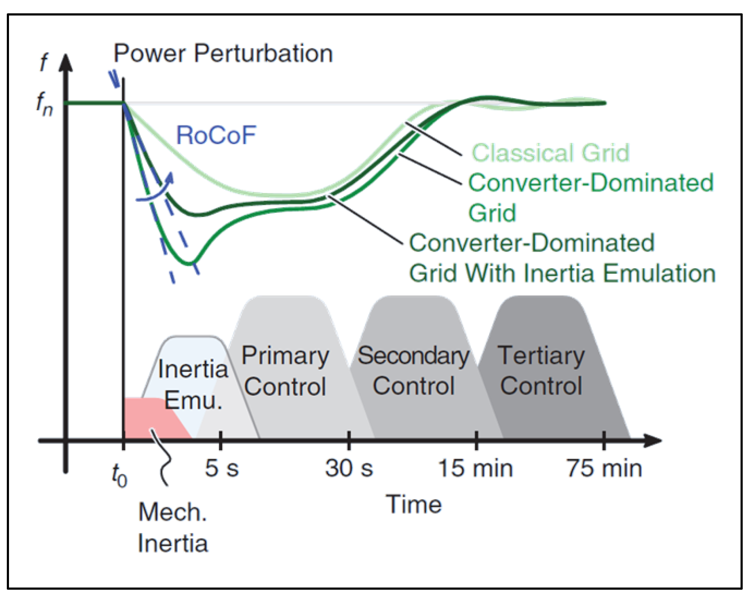
Figure 8 shows the frequency control levels for traditional electrical systems, as follows:
Mech Inertia: Mechanical inertia, provided by synchronous generators;
Inertia Emu.: Virtual inertia, provided by BESS, topic 2.3.10;
Primary Control: Frequency Regulation, topic 2.3.9;
Secondary Control: Rotating Reserve, topic 2.3.8;
Tertiary Control: Supplementary Reserve, topic 2.3.8;
Figure 8. Energy Reserve.
Sustainability 14 13765 g008

3. Methodology

The methodology used in this work consists of the combination of several applications of storage systems aimed at microgrids, with the main objectives of enhancing the diesel economy generated by the photovoltaic system and minimizing the power variations imposed on the Diesel Genset. For the proposed study, it was considered that the Gensets always operate in load sharing mode, where all generated power is divided equally between the connected machines, respecting the minimum operating limit of the machines. The following topics describe the operating modes of each of the storage system applications.

3.1. Applications

3.1.1. Excess Energy Recapture

In traditional isolated systems, the balance between generation and consumption is carried out through the control of the Genset’s, so that load variations are compensated by an increase or decrease in the generation. However, with the application of photovoltaic systems, due to the lack of control of the main source, it is possible the occurrence of scenarios where the generation exceeds the load consumption, causing a waste of energy. This scenario intensifies as the power of the PV system increases.
Figure 9 shows the PV generation and consumption curves for a hypothetical day, highlighting the effect of surplus energy, which can be used to recharge the storage system and later use.
Storage systems are an alternative for the use of surplus energy and subsequent use, enhancing the economy of diesel since more energy comes from a renewable source. As the PV system grows, more surplus energy is generated, bringing greater viability to the application of storage systems. Since this is the application with the highest economic return for BESS in the microgrid, priority is given to its execution over other functionalities.
In line with the strategy of prioritizing the recharge of the storage system with surplus energy, a controlled discharge is proposed in two scenarios. The first scenario occurs when more than one Genset is in operation; in this way, the calculation of the required discharge power of the storage system for the sequential shutdown of the machines is performed. In this way, based on the power and energy available in BESS, as many machines as possible are turned off, ensuring that the machines that remain on continue their operation at the optimum point of efficiency.
This strategy aligns the decrease in diesel consumption by reducing the energy demanded by the Genset’s with the increase in the generation efficiency of the remaining Genset’s, seeking the optimal point of operation.
For example, if three Gensets are operating at 80% of their power (3 × 80% = 240%), the power required to turn off a machine will be equal to 40% of its rated power. If the storage system has enough power and energy to shut down a machine, it will discharge the equivalent of 40% of the Genset power, causing its shutdown, keeping the two remaining machines at their optimal operating point. If the storage system has available power and energy equivalent to 140% of the Genset power, it will shut down two machines, keeping the remaining machine at its optimal operating point.
The second algorithm control scenario occurs when only one Genset is in operation. In the proposed configuration, at least one Genset must remain connected and generating, in order to guarantee the voltage and frequency of the network. Based on this, it is not possible to discharge the storage system to the point of causing the total shutdown of the Diesel generation system.
However, it is proposed to configure a target power of operation of the Genset until the storage system can perform the discharge. Ideally, this target power should not present low Genset efficiency values.
For example, if the configured target power is 75% of the rated power and the generator is operating at 100% of the rated power, the storage will discharge with a power equivalent to 25%. In another hypothetical scenario, using the same target power setting of 75%, but operating the Genset at 50% of rated power, the storage system does not perform unloading or recharging operations.
It is worth mentioning that this configured parameter is different from the minimum operating power of the Genset. The minimum operating power is an immutable value, so continuous operation below the minimum power can cause irreversible damage to the machine.

3.1.2. Power Smoothing of Photovoltaic Generation

As pointed out in topic 2.3.6, the power smoothing of photovoltaic generation is an important service provided by storage systems. In this work, two modifications are proposed to the commonly used methods.
In traditional microgrids, power generation is based on Gensets; in this way, since this is the main source, all load variations are absorbed by this set. Based on this, it is proposed to apply power smoothing in the sum of the load consumption data with the PV generation, creating a real smoothing scenario for the Genset’s, unifying the power smoothing and load leveling applications in a single algorithm.
This modification aims to focus the application of the storage system on reducing the variations imposed on the Genset and not on the output of the PV system. As an example, if the PV system has a positive variation in generation and the load also presents an increase in consumption, this variation against the Genset can be cancelled without interference from storage, depending on the amplitude of the events. The opposite is also valid, since a drop in generation can be potentiated with an increase in consumption, generating a high-power ramp in the Genset’s.
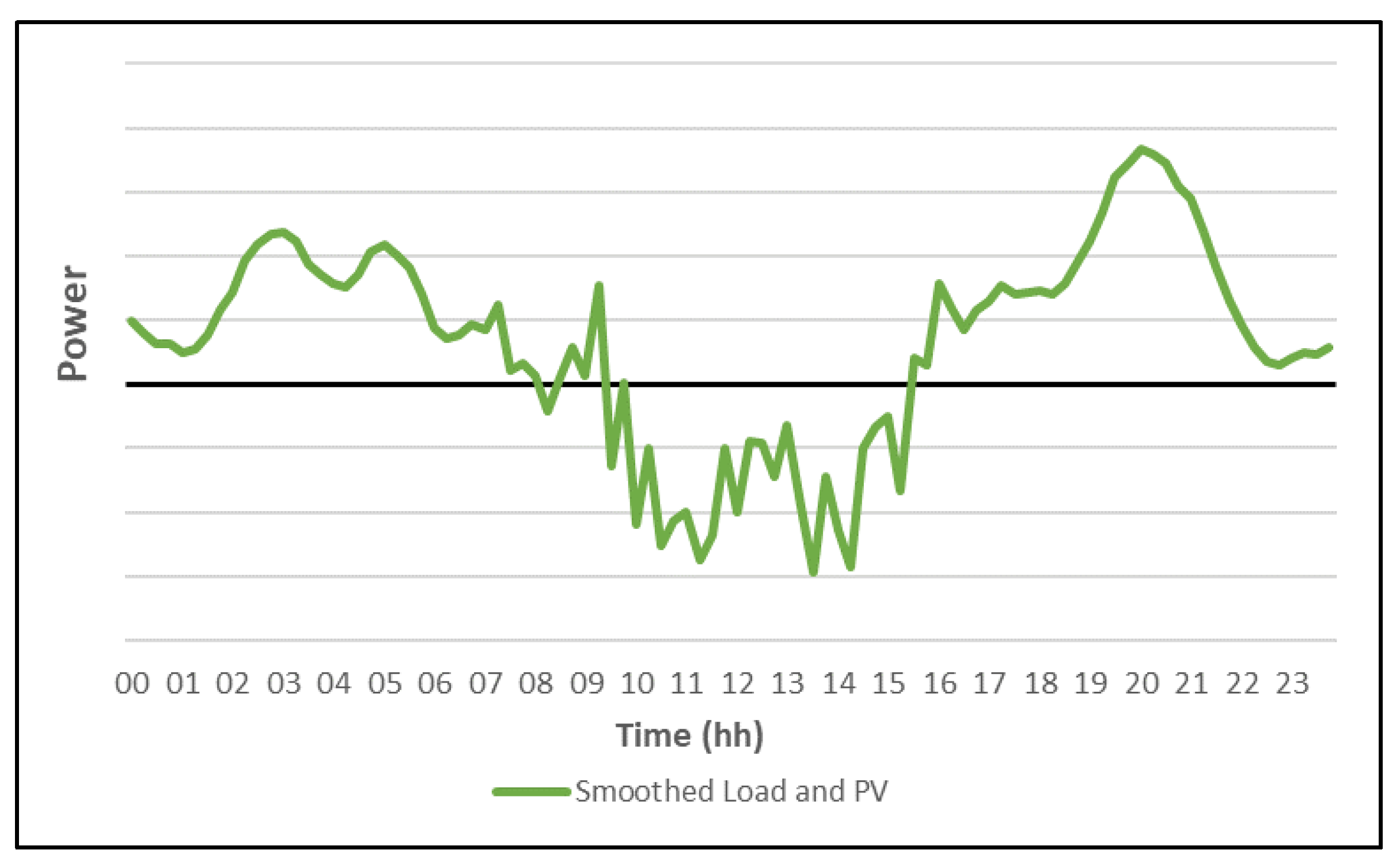
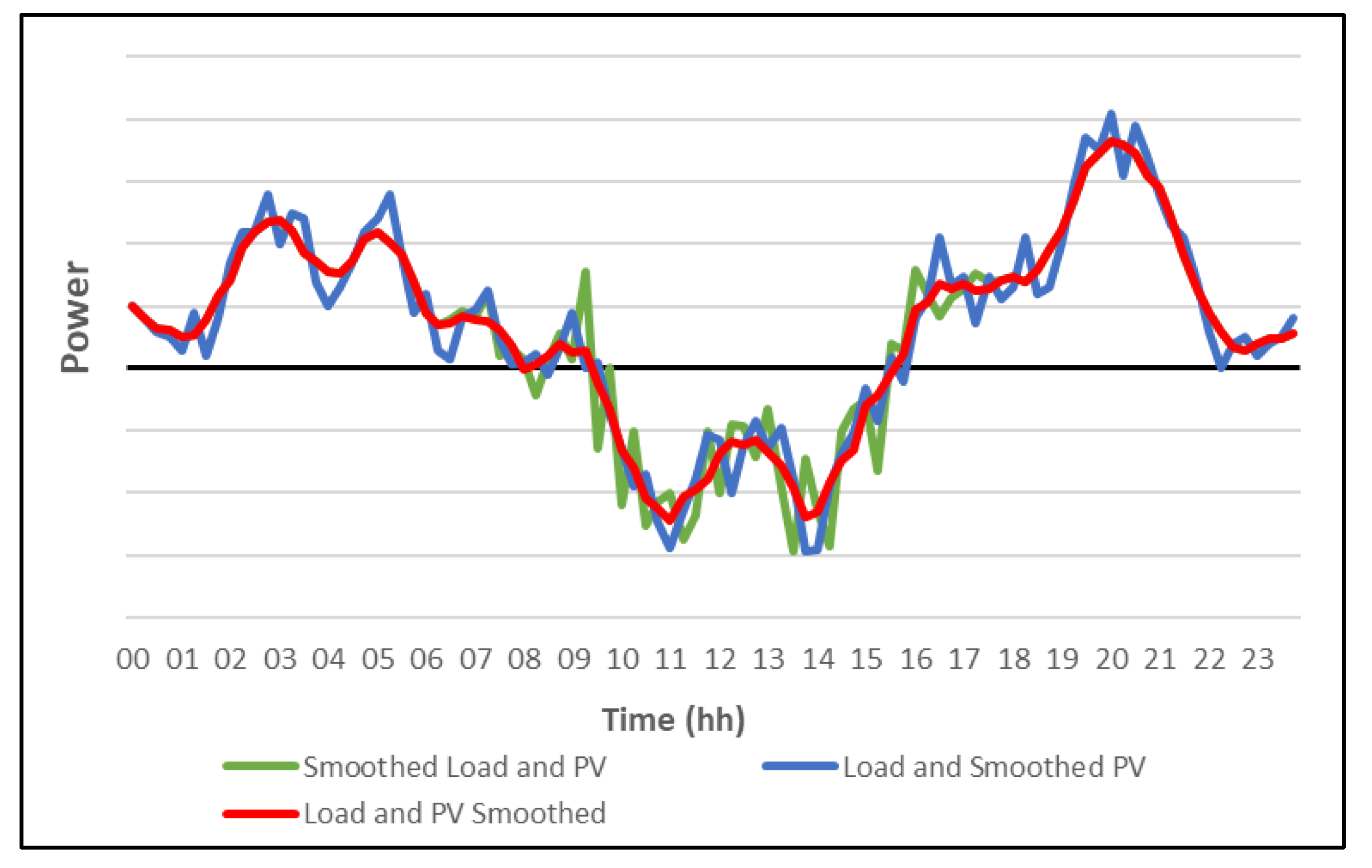
Figure 10, Figure 11, Figure 12, Figure 13, Figure 14, Figure 15 and Figure 16 are possible to observe, for a hypothetical day: i. PV generation; ii. load consumption; iii. load consumption + PV generation; iv. smoothed load consumption + PV generation; v. load consumption + smoothed PV generation; saw. smoothed load consumption and PV generation; vii. Comparison of smoothing.
Another point of great importance for the correct application of smoothing methods, as studied by Pinheiro, A. in [35], refers to the SoC level of the storage system. Depending on load and PV generation variations, scenarios may occur where the consumption increase always happens abruptly and the drops in soft variations, causing an imbalance in the SoC at the beginning and end of the day, since BESS would only carry out operations to smooth out the abrupt rise in consumption, without carrying out recharging operations, as the drop in consumption did not exceed the threshold rate.
Based on this, the proposed smoothing method is a modification of the ramp rate strategy, recharging or discharging the system to reach the desired SoC with energy from the Gensets, without extrapolating the designated threshold rate.
In other words, if the Load + PV set decreases consumption in relation to the previous smoothed power, enough to exceed the threshold rate, the battery bank must consume part of this power, recharging to keep the variation seen by the Genset within the admissible limit, and vice versa. However, if the variation is within the limits (that is, no limit exceeded), the BESS can perform the function of returning to the ideal SoC, recharging or discharging, without extrapolating the limit rate of change.

3.1.3. Capacity Reserve

As presented in 2.3.8, isolated generation systems must work with an available reserve power so that any sudden load increases or partial failures in the generation system can be met without violating the established voltage and frequency values. However, due to this reserve percentage, it is likely that the generators will start to operate outside the optimal consumption ranges, since this value is found close to the rated power of the machine.
As storage systems are capable of providing power and energy quickly, this power reserve can be shifted from the Genset’s to the storage system, so that the optimal range of consumption of the Genset can be reached more easily, since there is greater use of available power.
In this work, it is proposed to perform the capacity reserve function of the generation system in the storage system. For the execution of this functionality, the power available by the storage system is verified, conflicting with the state of load and power limits of the equipment. If full power is not available, the diesel generation system returns to the execution of the functionality, which can also be shared, with part of the reserve coming from storage and part from the Genset’s.

3.2. Proposed System

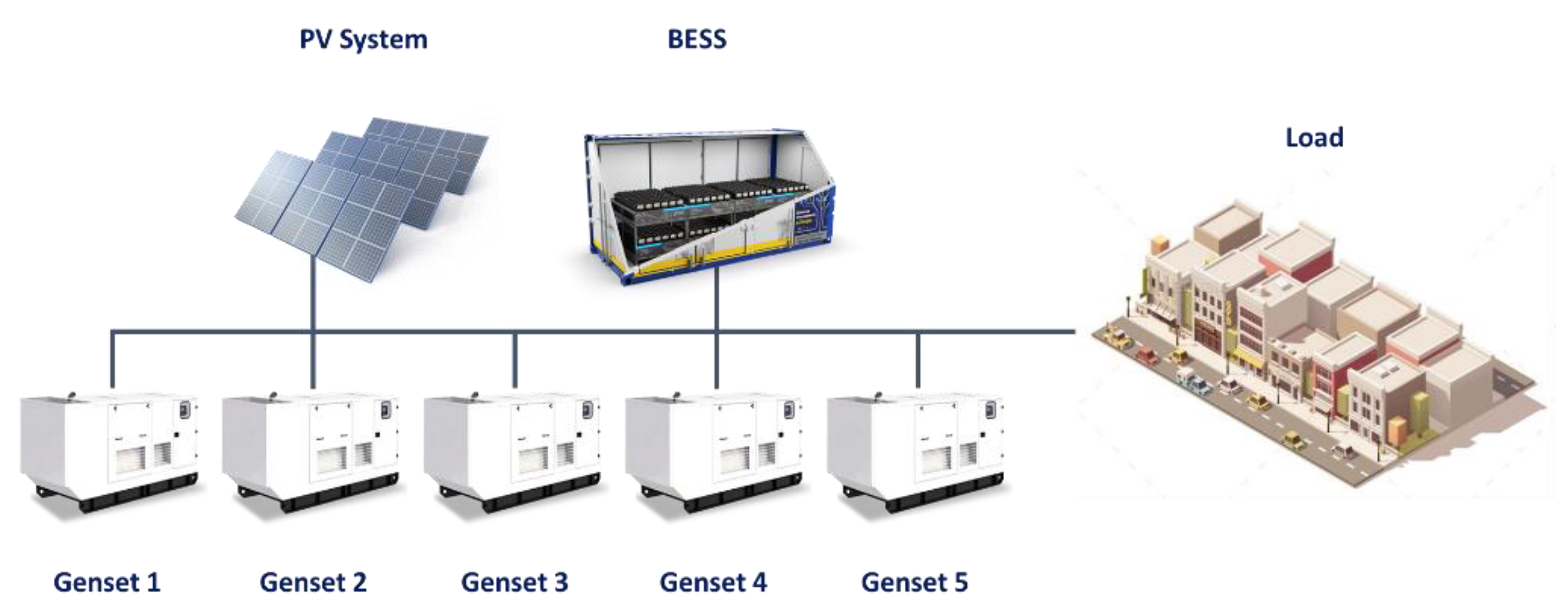
In the proposed microgrid, the PV system, five Gensets of equal power, and the storage and load system are connected to the AC bus, as illustrated in Figure 17.
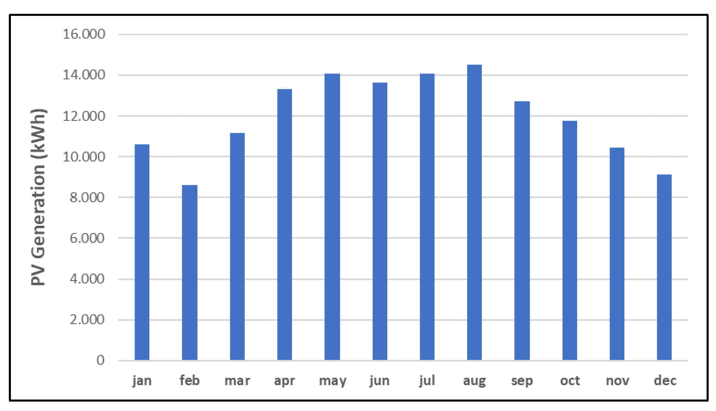
PV system: With peak power being an input variable, the simulated PV system has an average monthly generation of 120 kWh/kWp/month and a monthly generation profile as shown in Figure 18. To perform the simulations, the generation profile was determined as equivalent to 1 kWp, so multipliers on top of the base profile were applied to reach the peak power target. Figure 18 presents the monthly generation for a simulated 100 kWp system.
Genset: The simulated Gensets have a nominal power of 500 kW and a minimum operating power of 125 kW, with the five machines having the same configuration. The consumption curve, shown in Figure 19, is based on the data presented in [36].
Storage System: With useful energy being an input variable, the simulated storage system has a round-trip efficiency of 85% and a power/useful energy ratio of 1.
Load: The base load for the simulations has a peak consumption of 1.25 MW and an average consumption of 500 MWh/month. The typical consumption curve is shown in Figure 20 and the monthly consumption is shown in Figure 21.

3.3. Simulations and Results Analysis

The simulations were carried out for a period of one year of consumption and generation, with a time interval of 5 min between samples, thus, dynamic stability studies are not contemplated in this work.
For the amplitude of the subsystems, analyses were carried out with photovoltaic systems from 0 to 4 MWp, in steps of 500 kWp, and storage system from 0 to 6 MWh, in steps of 500 kWh.
For the analysis of results, the microgrids operation indicators were standardized, as follows:
  • Diesel consumption (L);
  • Surplus Energy (kWh);
  • Energy Recharged by BESS (kWh);
  • PV generation (kWh);
  • PV share in the energy matrix (%)
  • Hours of Operation of Gensets (h);
  • Average operating power of Gensets (kW);
  • Percentage of Gensets power variation within the established limits (%);
  • Variation in the average power of the Gensets;
  • Distribution of power variation bands for Gensets.

4. Results

4.1. Energy Balance

In this section, the energy balance of the microgrid will be analyzed, presenting the effectiveness of the implementation of the hybrid system to reduce diesel consumption, increase the PV share, energy recharged by BESS, and the sensitivity analysis with the variation of these components.
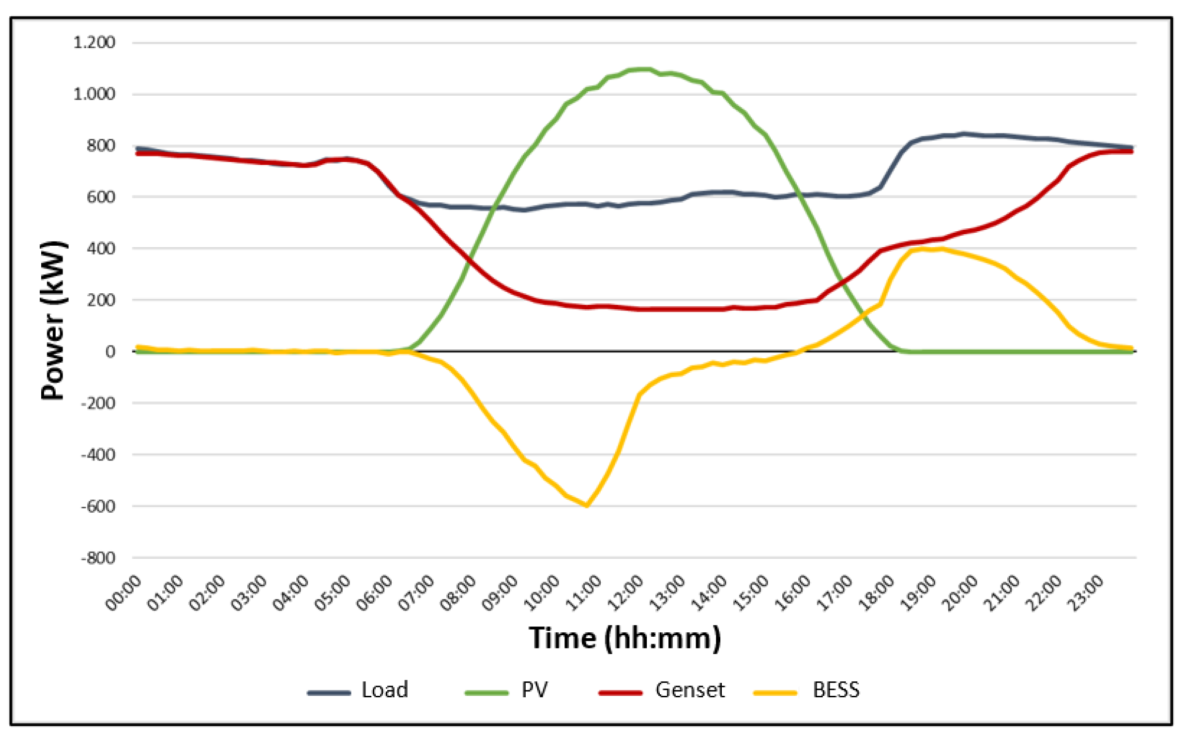
Seeking to simplify the understanding of the behavior of the microgrid and the results achieved by the operation algorithm, Figure 22, Figure 23 and Figure 24 show the standard operation data for scenarios of low, medium, and high penetration of renewables.
In the scenario of low penetration of renewables (Figure 22), it is possible to observe a decrease in the operating power of the Genset in relation to the consumption of the load during the period of higher PV generation, followed also by a slight reduction, where the discharge of the BESS is found. This reduction in operating power is due to PV participation in the generation matrix and storage as an element for absorbing excess energy.
In this scenario, it is possible to point out that even if the PV generation does not exceed the consumption of the load, there is surplus energy in the microgrid, since the minimum generation to be exported by the Gensets is 125 kW.
In the scenario of medium penetration of renewables (Figure 23), it is possible to observe that the PV system has greater participation in the microgrid, with more surplus energy being generated. In the same way, BESS recharges and discharges more expressively, extending the time in which the generator operates with less power than the load consumption.
For this result, it is possible to observe that close to 11:00 am, BESS decreases the recharge power, even if there is excess energy in the microgrid. This happens because the state of charge has reached the maximum value and there is no more storage capacity, causing this excess energy to be wasted.
In the scenario of high penetration of renewables (Figure 24), the surplus energy due to high generation during the day is even more evident. The PV overtakes the load during almost the entire generation period and is followed by a controlled discharge of the storage system, causing the generator to operate at close to its minimum power throughout the entire period.
Similar to the previous analysis, around 11:00 a.m. the charging power of BESS decreases, since charging is complete and there is no space for storage.
As the main parameter to be evaluated in economic analyses, since it corresponds to the component with the highest operating cost in a microgrid, diesel consumption is presented in Figure 25. The operation analysis is performed for systems PV from 0 to 4 MWp, in steps of 500 kWp and BESS from 0 to 6 MWh, in steps of 500 kWh.
At points of lower PV insertion (0 and 500 kWp), it is noted that the change in the size of the storage system does not present significant differences in diesel consumption. This is mainly due to the low surplus energy generated in these scenarios, the main source of BESS recharge. As the PV system grows, the more effective the storage system is, as there is more surplus energy available for recharging.
As an analysis of the operating trends, it is highlighted that the increase in the PV system presents greater effectiveness for the relative reduction in diesel consumption in the first steps (0 to 1 MWp). This is because most of the energy generated in these scenarios is used by the microgrid. With the increase in the PV system, it is possible to observe a stabilization trend in the reduction in diesel consumption, so that this stabilization behavior is observed earlier in scenarios with lower insertion of BESS.
As a complement to the PV trend analysis, it is noteworthy that the first step of inserting storage (0 to 500 kWh) presents a greater percentage reduction in diesel consumption, since the power smoothing and capacity reservation services pass to be performed.
In addition, with the increase in BESS, it is possible to notice that in the final stages (5.5 MWh to 6 MWh) the reduction in diesel loses percentage effectiveness, also reaching a stabilization trend. This behavior is mainly due to the high energy stored and the need to keep at least one generator in operation to guarantee the voltage and frequency reference, even at minimum power.
Complementary to the analyses carried out for diesel consumption, Figure 26 shows the surplus energy of the microgrid with the increase in PVS (Photovoltaic System) and BESS. For the lower PV insertion scenarios (0 to 500 kWp) there is no surplus energy, since the load consumption remains above the PV generation + Genset minimum generation. However, it is noted that the increase in PVS is accompanied by an increase in excess energy, even if minimized with the insertion of BESS.
The trend of constant increase in excess energy, even with the insertion of larger BESS is noticeable, explained by the need to keep at least one Genset in operation, even at minimum power.
For the recharged energy of the BESS (Figure 27), it is noted that the stabilization of the parameter is reached earlier for smaller storage capacities. Similar to previous analyses, this occurs due to the limitation of BESS recharge to absorb excess energy from the plant. This analysis becomes important, mainly for economic aspects, as it details the real need for storage capacity through BESS recharge.
Taking the 1 MWp PVS as an example, it is possible to infer that from the point of view of energy use, there is no considerable difference between using a 2 MWh or 6 MWh BESS, since the energy recharged by both systems is close. In this scenario, using a higher capacity system would bring an extra cost to the system, which could lead to the economic unfeasibility of the investment.
Adding to the analysis of the energy balance of the microgrid, Figure 28 shows the PV participation in meeting the load in view of the increase in the generation and storage system. Additionally, the percentage of PV generation was inserted in relation to the total consumption of the load, in order to illustrate the low use of generated energy for larger systems.
With the low penetration of PVS, it is clear that the PV share follows the percentage generation compared to consumption, as there is low surplus energy in these scenarios. As the PV insertion increases, the greater the dispersion between generation and use, even with the increase in BESS, and a trend towards stabilization of participation is noted.
As already pointed out in previous analyses, this stabilization takes place far from the point of 100% renewable penetration due to the need to guarantee the operation of at least one Genset. It is important to emphasize that different load profiles will bring different results regarding the penetration of renewables in the system, being the analysis of varied loads outside the scope of this work.

4.2. Capacity Reserve

One of the functions developed for the operation algorithm refers to the capacity reservation of the microgrid. In this proposal, the reserve power is transferred to BESS, if available. This feature aims to reduce operating time and increase the average working power of the Genset’s.
To exemplify the proposed strategy, considering a scenario with exclusive generation by Genset’s and 30% of the capacity reserve, for a load of 500 kW, a minimum available power of 650 kW will be required. As the generator simulated for this microgrid has a maximum power of 500 kW, two generators would be needed working in parallel. If this functionality is performed by another system, this load could be serviced with only one generator connected.
In the scenario where the reserve function is not performed by the Genset, the operation is based on one generator, with a working power of 500 kW, compared to two generators with a working power of 250 kW. Note, for this example, that performing the capacity reserve function reduces the operating time by half and the operating power remains at the optimal point, bringing better efficiency in the generated L/kWh ratio and lower maintenance costs, since the machine spends less time in operation.
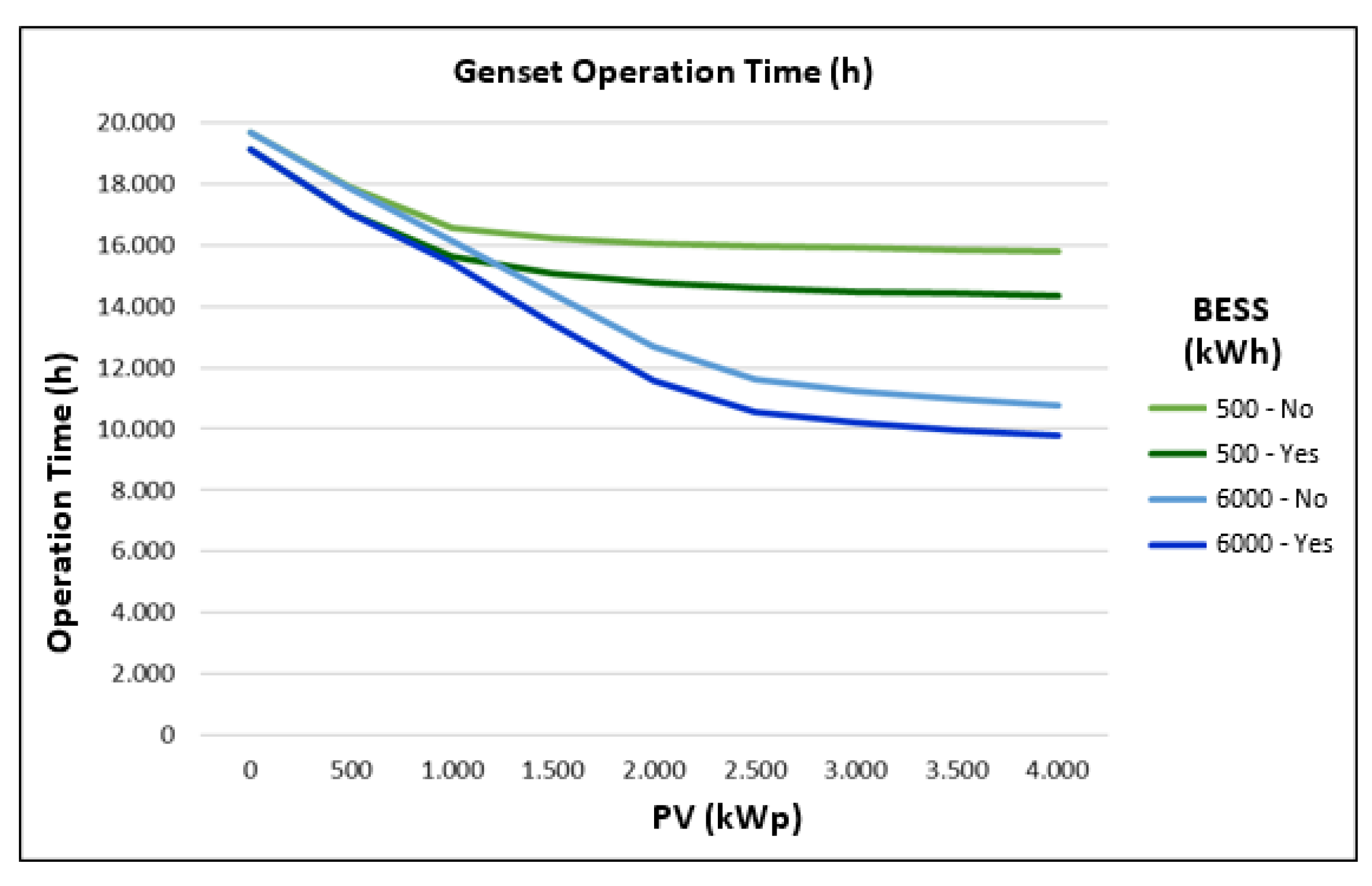
Figure 29 shows the graph with the two extremes of the BESS analyzes (0.5 MWh and 6 MWh). For the system with a capacity of 0.5 MWh, it is possible to achieve a reduction of approximately 900 h of operation for smaller PVSs (0.5 to 1 MWp) and 1500 h for the PVS of 4 MWp.
For the system with a capacity of 6 MWh, the same reduction is achieved for scenarios with lower penetration of renewables and a reduction of approximately 1000 h considering PVS of 6 MWp.
As a consequence of the reduction in the reserve percentage of the Genset’s, an increase in the average operating power of the machines is observed. Figure 30 shows the average power data for the 500 kWh BESS. Of note is an average power increase of 15 kW for scenarios with lower PV penetration and 28 kW for the scenario with higher penetration.
Figure 31 shows the average power data for the 6 MWh BESS. The same reduction of 15 kW for smaller PVSs and 41 kW for the scenario of higher penetration stands out.

4.3. Power Smoothing

The power smoothing functionality has a main objective to limit the variation imposed on the Genset, which is caused by the load or PVS. This variation minimization seeks to increase the voltage and frequency stability of the network (parameters not analyzed in this work) and minimize the chance of damage to the Genset’s due to the inertia found in the motors, which contrast with abrupt load variations.
In short, when executing the functionality, BESS analyzes the working power of the Genset in the previous instant and controls the maximum variation in ±1%/minute. It should be noted that this parameter can be configured according to the needs of the Gensets used.
Figure 32 shows the power variation data within the limits of ±1%/min for a BESS of 500 kWh. It is possible to notice that, without the execution of the functionality, the limits present a high rate of violation, remaining below 80% for low penetration of renewables (0.5 to 1.5 MWp) and close to 83% for higher penetrations.
The increase in data with a variation rate within the limits for larger PVSs is basically due to the generation limitation at times when the generation exceeds the load consumption. As illustrated in Figure 23 and Figure 24, in high-generation scenarios, the Genset output is kept fixed at the minimum power, making the observed variation null. With the functionality running, all scenarios are kept above 95%, proving the effectiveness of the proposed solution even for low storage capacity.
Figure 33 shows the power variation data within the limits of ±1%/min for a BESS of 6 MWh. In a similar way to the behavior of the lower capacity system, the effectiveness of the functionality stands out, guaranteeing 95% of the variation within the limit established for low PV penetration (0.5 MWp) and above 98% for medium and large systems (2 to 4 MWp).
Without functionality running, data within limits remains below 80% for low penetration of renewables (0.5 to 1.0 MWp) and increases up to 94% as PVS increases. As explained in the previous analysis, the increase in the percentage of data within the established variation rate is due to the limitation of PV generation to guarantee the minimum operating power of the Genset.
As a consequence of BESS operation, keeping the power variation within the established limit of ±1%/min, it is also possible to observe a considerable reduction in the average power variation, in kW/min. Figure 34 shows the power variation data, in kW/min, for the 500 kWh BESS, with and without the power smoothing function. For systems with low penetration of renewables it is possible to observe a reduction of approximately 20% of the average variation (10.4 kW to 8.4 kW). For the highest PV insertion point (4 MWp) a reduction of approximately 29% of the average variation is achieved (10.1 kW to 7.2 kW).
For the analysis of the system with a BESS of 6 MWh, shown in Figure 35, it is possible to observe a reduction of the same 20% in low PV insertion (10.4 kW to 8.4 kW) and of 22% for higher insertions (4.3 kW to 3.3 kW). Additionally, noteworthy is the natural reduction in the average power variation for scenarios with greater PV insertion, since, due to the phenomenon presented in the previous analyses, the larger the PV + BESS set, the longer the generator remains at minimum operating power, or with the output power controlled by the action of BESS, according to the strategy of using surplus energy and optimized discharge, presented in Figure 34.
Figure 36 shows the power variation distribution for the simulation performed, 2 MWp–500 kWh. This representation illustrates the scenario with and without the application of the power smoothing strategy, where BESS performs the variation limitation if it has a modulus greater than 1%. As seen from this scenario, it is possible to detect that without the application of the smoothing strategy, there are variations that violate these limits.
It is also noted from Figure 36 that all data with a population outside the allowed variation zone of −1% to 1% had a reduction in their occurrence, due to the application of the smoothing strategy.

5. Conclusions

Throughout this work, in which the control strategy for microgrids was developed and applied, it was possible to verify the effectiveness of the proposal with reductions in diesel consumption with values greater than 50%, reduction in Genset operating time by up to 50%, increase in the average operating power, and guarantee of power variation within the limits with the confidence of up to 99%, all results being variable according to the level of PV + BESS penetration. The proposed strategy contributes with a new perspective of BESS applications in microgrids, enabling the realization of simultaneous and combined functionalities, such as intelligent discharge control, Genset power smoothing, and sharing of the rotating reserve. The proposed study was limited to the construction and demonstration of the effectiveness of the strategy for applications in microgrids with AC coupling, with the guarantee of at least one generator working as a voltage and frequency reference source. For future work, a detailed economic analysis of each of the components and of the complete microgrid is suggested, in order to evaluate the combination of PVS, BESS, and Genset that best relates to the technical and economic benefits, being able to use sensitivity matrices for different estimates of the cost of components, diesel, and maintenance.

Author Contributions

Conceptualization, F.R., A.P., R.N., W.d.A.S.J., M.A.M. and M.H.N.M.; data curation, F.R., W.d.A.S.J., M.A.M. and M.H.N.M.; formal analysis, R.N. and M.H.N.M.; investigation, F.R., A.P., W.d.A.S.J., M.A.M., A.A. and M.H.N.M.; methodology, R.N., M.A.M. and M.H.N.M.; resources, A.P., R.N. and W.d.A.S.J.; software, F.R. and M.H.N.M.; supervision, M.A.M. and M.H.N.M.; validation, A.A.; visualization, A.P. and A.A.; writing—original draft, F.R., A.P., R.N., W.d.A.S.J., M.A.M. and M.H.N.M.; writing—review and editing, F.R., A.P., R.N., W.d.A.S.J., M.A.M., A.A. and M.H.N.M. All authors have read and agreed to the published version of the manuscript.

Funding

This research received no external funding.

Institutional Review Board Statement

Not applicable.

Informed Consent Statement

Not applicable.

Data Availability Statement

Not applicable.

Conflicts of Interest

The authors declare no conflict of interest.

References

  1. Dayalan, S.; Gul, S.S.; Rathinam, R.; Fernandez Savari, G.; Aleem, S.H.A.; Mohamed, M.A.; Ali, Z.M. Multi-Stage Incentive-Based Demand Response Using a Novel Stackelberg–Particle Swarm Optimization. Sustainability 2022, 14, 10985. [Google Scholar] [CrossRef]
  2. Chen, W.; Liu, B.; Nazir, M.S.; Abdalla, A.N.; Mohamed, M.A.; Ding, Z.; Bhutta, M.S.; Gul, M. An Energy Storage Assessment: Using Frequency Modulation Approach to Capture Optimal Coordination. Sustainability 2022, 14, 8510. [Google Scholar] [CrossRef]
  3. Peng, F.; Su, H.; Li, P.; Song, G.; Zhao, J. An Interactive Operation Strategy for Microgrid Cooperated with Distribution System Based on Demand Response; IEEE: New York, NY, USA, 2015; ISBN 9781467371063. [Google Scholar]
  4. Zhang, Y.; Liu, B.; Zhang, T.; Guo, B. An Intelligent Control Strategy of Battery Energy Storage System for Microgrid Energy Management under Forecast Uncertainties. Int. J. Electrochem. Sci. 2014, 9, 4190–4204. [Google Scholar]
  5. Khalid, M. A Review on the Selected Applications of Battery-Supercapacitor Hybrid Energy Storage Systems for Microgrids. Energies 2019, 12, 4559. [Google Scholar] [CrossRef] [Green Version]
  6. Huang, Y.; Masrur, H.; Shigenobu, R.; Hemeida, A.M.; Mikhaylov, A.; Senjyu, T. A Comparative Design of a Campus Microgrid Considering a Multi-Scenario and Multi-Objective Approach. Energies 2021, 14, 2853. [Google Scholar] [CrossRef]
  7. Aziz, A.S.; Tajuddin, M.F.N.; Adzman, M.R.; Ramli, M.A.M.; Mekhilef, S. Energy Management and Optimization of a PV/Diesel/Battery Hybrid Energy System Using a Combined Dispatch Strategy. Sustainability 2019, 11, 683. [Google Scholar] [CrossRef] [Green Version]
  8. Arévalo-Cordero, P.; Benavides, D.J.; Espinoza, J.L.; Hernández-Callejo, L.; Jurado, F. Optimal Energy Management Strategies to Reduce Diesel Consumption for a Hybrid Off-Grid System. Rev. Fac. Ing. 2020, 98, 47–58. [Google Scholar] [CrossRef]
  9. Delille, G.; François, B.; Malarange, G. Dynamic Frequency Control Support: A Virtual Inertia Provided by Distributed Energy Storage to Isolated Power Systems. In Proceedings of the 2010 IEEE PES Innovative Smart Grid Technologies Conference Europe (ISGT Europe), Gothenburg, Sweden, 11–13 October 2010; pp. 1–8. [Google Scholar]
  10. Denholm, P.; Margolis, R.M. Evaluating the Limits of Solar Photovoltaics (PV) in Electric Power Systems Utilizing Energy Storage and Other Enabling Technologies. Energy Policy 2007, 35, 4424–4433. [Google Scholar] [CrossRef]
  11. Zhao, B.; Zhang, X.; Li, P.; Wang, K.; Xue, M.; Wang, C. Optimal Sizing, Operating Strategy and Operational Experience of a Stand-Alone Microgrid on Dongfushan Island. Appl. Energy 2014, 113, 1656–1666. [Google Scholar] [CrossRef]
  12. Vieira, G.T.T.; Pereira, D.F.; Taheri, S.I.; Khan, K.S.; Salles, M.B.C.; Guerrero, J.M.; Carmo, B.S. Optimized Configuration of Diesel Engine-Fuel Cell-Battery Hybrid Power Systems in a Platform Supply Vessel to Reduce CO2 Emissions. Energies 2022, 15, 2184. [Google Scholar] [CrossRef]
  13. Mohamed, M.A. A relaxed consensus plus innovation based effective negotiation approach for energy cooperation between smart grid and microgrid. Energy 2022, 252, 123996. [Google Scholar] [CrossRef]
  14. Ralon, P.; Taylor, M.; Ilas, A.; Diaz-Bone, H.; Kairies, K. Electricity Storage and Renewables: Costs and Markets to 2030; International Renewable Energy Agency: Abu Dhabi, United Arab Emirates, 2017; ISBN 9789292600389. [Google Scholar]
  15. Mohamad, F.; Teh, J.; Lai, C.M. Optimum allocation of battery energy storage systems for power grid enhanced with solar energy. Energy 2021, 223, 120105. [Google Scholar] [CrossRef]
  16. Ramos, F.O.; Neto, M.M.B.; Pinheiro, A.L.; Junior, W.A.S.; Lima, R.N. A Real Case Analysis of a Battery Energy Storage System for Energy Time Shift, Demand Management, and Reactive Control. In Proceedings of the 2021 IEEE PES Innovative Smart Grid Technologies Conference-Latin America (ISGT Latin America), Quito, Ecuador, 15 September 2021. [Google Scholar]
  17. Metwaly, M.K.; Teh, J. Optimum network ageing and battery sizing for improved wind penetration and reliability. IEEE Access 2020, 8, 118603–118611. [Google Scholar] [CrossRef]
  18. Ribeiro, P.F.; Johnson, B.K.; Crow, M.L.; Arsoy, A.; Liu, Y. Energy Storage Systems for Advanced Power Applications. Proc. IEEE 2001, 89, 1744–1756. [Google Scholar] [CrossRef]
  19. Fidalgo, J.N.; Couto, M.; Fournié, L. The worth of network upgrade deferral in distribution systems—Truism or myth? Electr. Power Syst. Res. 2016, 137, 96–103. [Google Scholar] [CrossRef]
  20. Liu, L.; Wang, Y.; Zhao, Y. The Energy Storage System Control Research Based on Black-Start. In Proceedings of the 2014 China International Conference on Electricity Distribution (CICED), Shenzhen, China, 23 September 2014; pp. 1472–1476. [Google Scholar]
  21. Mielczarski, W. Impact of Energy Storage on Load Balancing. In Proceedings of the 2018 15th International Conference on the European Energy Market (EEM), Lodz, Poland, 27–29 June 2018; Institute of Electrical and Electronics Engineers (IEEE): New York, NY, USA, 2018; pp. 1–5. [Google Scholar]
  22. Izidio, D.M.F.; de Mattos Neto, P.S.G.; Barbosa, L.; de Oliveira, J.F.L.; da Marinho, M.H.N.; Rissi, G.F. Evolutionary Hybrid System for Energy Consumption Forecasting for Smart Meters. Energies 2021, 14, 1794. [Google Scholar] [CrossRef]
  23. IRENA. Renewable Capacity Statistics 2020; International Renewable Energy Agency: Abu Dhabi, United Arab Emirates, 2020; ISBN 9789292602390. [Google Scholar]
  24. de Mattos Neto, P.S.G.; de Oliveira, J.F.L.; Domingos, D.S.; Siqueira, H.V.; Marinho, M.H.N.; Madeiro, F. An Adaptive Hybrid System Using Deep Learning for Wind Speed Forecasting. Inf. Sci. 2021, 581, 495–514. [Google Scholar] [CrossRef]
  25. Mohamed, M.A.; Almalaq, A.; Abdullah, H.M.; Alnowibet, K.A.; Alrasheedi, A.F.; Zaindin, M.S.A. A distributed stochastic energy management framework based-fuzzy-PDMM for smart grids considering wind park and energy storage systems. IEEE Access 2021, 9, 46674–46685. [Google Scholar] [CrossRef]
  26. Haque, M.E.; Sakib Khan, M.N.; Islam Sheikh, M.R. Smoothing Control of Wind Farm Output Fluctuations by Proposed Low Pass Filter, and Moving Averages; International Conference on Electrical & Electronics Engineering: New York, NY, USA, 2015; ISBN 9781467378192. [Google Scholar]
  27. Alevizakos, V.; Chatterjee, K.; Koukouvinos, C.; Lappa, A. A Double Moving Average Control Chart. Commun. Stat. Simul. Comput. 2020, 37, 1696–1708. [Google Scholar] [CrossRef]
  28. Martins, J.; Spataru, S.; Sera, D.; Stroe, D.I.; Lashab, A. Comparative Study of Ramp-Rate Control Algorithms for PV with Energy Storage Systems. Energies 2019, 12, 1342. [Google Scholar] [CrossRef] [Green Version]
  29. Mohamed, M.A.; Abdullah, H.M.; Al-Sumaiti, A.S.; El-Meligy, M.A.; Sharaf, M.; Soliman, A.T. Towards energy management negotiation between distributed AC/DC networks. IEEE Access 2020, 8, 215438–215456. [Google Scholar] [CrossRef]
  30. Al-Shamma’a, A.A.; Hussein Farh, H.M.; Noman, A.M.; Al-Shaalan, A.M.; Alkuhayli, A. Optimal Sizing of a Hybrid Renewable Photovoltaic-Wind System-Based Microgrid Using Harris Hawk Optimizer. Int. J. Photoenergy 2022, 2022, 4825411. [Google Scholar] [CrossRef]
  31. Teh, J.; Lai, C.M. Reliability impacts of the dynamic thermal rating and battery energy storage systems on wind-integrated power networks. Sustain. Energy Grids Netw. 2019, 20, 100268. [Google Scholar] [CrossRef]
  32. Al-Shamma’a, A.A.; Alturki, F.A.; Farh, H.M. Techno-economic assessment for energy transition from diesel-based to hybrid energy system-based off-grids in Saudi Arabia. Energy Transit. 2020, 4, 31–43. [Google Scholar] [CrossRef] [Green Version]
  33. Zeng, L.; Xia, T.; Elsayed, S.K.; Ahmed, M.; Rezaei, M.; Jermsittiparsert, K.; Dampage, U.; Mohamed, M.A. A novel machine learning-based framework for optimal and secure operation of static VAR compensators in EAFs. Sustainability 2021, 13, 5777. [Google Scholar] [CrossRef]
  34. Unamuno, E.; Paniagua, J.; Barrena, J.A. Unified Virtual Inertia for Ac and Dc Microgrids. IEEE Electrif. Mag. 2019, 7, 56–68. [Google Scholar] [CrossRef]
  35. Pinheiro, A.L.; Ramos, F.O.; Neto, M.M.B.; Lima, R.N.; Bezerra, L.G.S.; Junior, W.A.S. A Review and Comparison of Smoothing Methods for Solar Photovoltaic Power Fluctuation Using Battery Energy Storage Systems. In Proceedings of the 2021 IEEE PES Innovative Smart Grid Technologies Conference-Latin America (ISGT Latin America), Quito, Ecuador, 15 September 2021. [Google Scholar]
  36. Caterpillar Inc. C18 500kW Diesel Generator Sets; Caterpillar Inc.: Peoria, IL, USA, 2019. [Google Scholar]
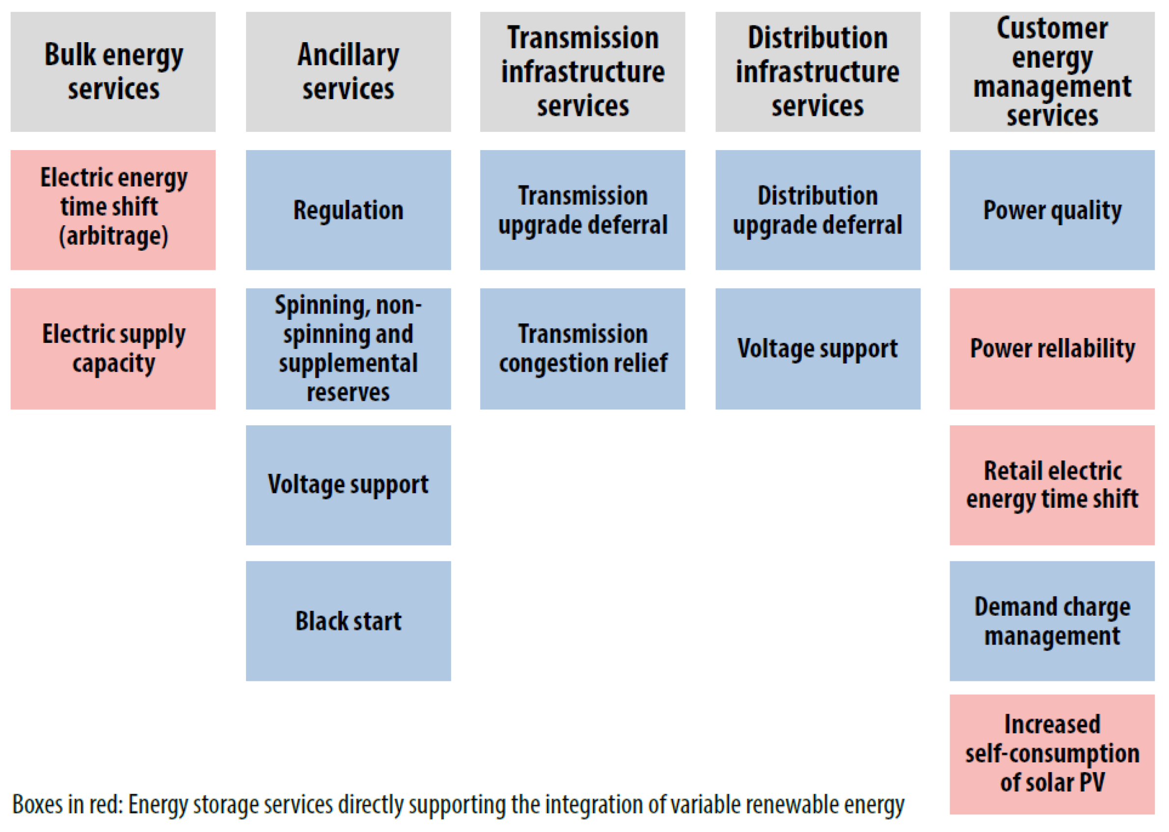
Figure 1. BESS Applications.
Sustainability 14 13765 g001
Figure 2. A typical operation of a storage system connected to the electricity grid.
Sustainability 14 13765 g002
Figure 3. Upgrade Deferral Application.
Sustainability 14 13765 g003
Figure 4. Load Leveling.
Sustainability 14 13765 g004
Figure 5. Typical operation of a storage system connected to a photovoltaic system.
Sustainability 14 13765 g005
Figure 6. Typical operation of a storage system performing the clipping utilization function.
Sustainability 14 13765 g006
Figure 7. Typical operation of a storage system performing the frequency control function.
Sustainability 14 13765 g007
Figure 9. Microgrid with PV Generation.
Sustainability 14 13765 g009
Figure 10. PV Generation.
Sustainability 14 13765 g010
Figure 11. Load Power.
Sustainability 14 13765 g011
Figure 12. Load and PV Power.
Sustainability 14 13765 g012
Figure 13. Smoothed Load and Natural PV.
Sustainability 14 13765 g013
Figure 14. Natural Load and Smoothed PV.
Sustainability 14 13765 g014
Figure 15. Load and Smoothed PV.
Sustainability 14 13765 g015
Figure 16. Smoothing Comparison.
Sustainability 14 13765 g016
Figure 17. AC Microgrid Topology.
Sustainability 14 13765 g017
Figure 18. PV Monthly Generation Profile.
Sustainability 14 13765 g018
Figure 19. Consumption Curve of Diesel Genset.
Sustainability 14 13765 g019
Figure 20. Daily Consumption Profile.
Sustainability 14 13765 g020
Figure 21. Monthly Consumption Profile.
Sustainability 14 13765 g021
Figure 22. Average Operation–Low Renewables Penetration Rate (1 MWp–0.5 MWh).
Sustainability 14 13765 g022
Figure 23. Average Operation–Medium Renewables Penetration Rate (2 MWp–2 MWh).
Sustainability 14 13765 g023
Figure 24. Average Operation–High Renewables Penetration Rate (4 MWp–6 MWh).
Sustainability 14 13765 g024
Figure 25. Diesel Consumption vs. PV and BESS insertion.
Sustainability 14 13765 g025
Figure 26. Excess Energy vs. PV and BESS insertion.
Sustainability 14 13765 g026
Figure 27. BESS Recharged Energy vs. PV and BESS Integration.
Sustainability 14 13765 g027
Figure 28. Renewable Penetration vs. PV and BESS Integration.
Sustainability 14 13765 g028
Figure 29. Diesel Genset Operating Hours vs. Capacity Reserve (500 kWh e 6000 kWh).
Sustainability 14 13765 g029
Figure 30. Average Diesel Genset Operating Power vs. Capacity Reserve (500 kWh).
Sustainability 14 13765 g030
Figure 31. Average Diesel Genset Operating Power vs. Capacity Reserve (6000 kWh).
Sustainability 14 13765 g031
Figure 32. Power Variation of the Diesel Genset within the Established Limit (500 kWh).
Sustainability 14 13765 g032
Figure 33. Power Variation of the Diesel Genset within the Established Limit (6000 kWh).
Sustainability 14 13765 g033
Figure 34. Average Power Variation of Diesel Genset vs. PV Power Smoothing (500 kWh).
Sustainability 14 13765 g034
Figure 35. Average Power Variation of Diesel Genset vs. PV Power Smoothing (6000 kWh).
Sustainability 14 13765 g035
Figure 36. Distribution of Power Variation of Diesel Genset (2 MWp–500 kWh).
Sustainability 14 13765 g036
Publisher’s Note: MDPI stays neutral with regard to jurisdictional claims in published maps and institutional affiliations.