Abstract
In order to obtain the minimum mining height that can play an effective protective role in the mining of the non-full coal protective layer in the Hongyang No. 3 coal mine and improve its economic benefits, the relationship between the mining height and the pressure relief of the protected layer is studied. Theoretical analysis is used to establish a calculation model of the goaf stress distribution law, with the mining height as a variable. The calculation model research results show that the mining height adjusts the goaf stress distribution by adjusting the range of the “three zones”. The force of the falling zone and the frustration zone on the goaf is approximately trapezoidal geostatic stress, and the roof stress in the vertical projection area of the trapezoidal waistline is not transmitted to the goaf. The development heights of the “two zones” are different at different mining heights, and the corresponding pressure-relief ranges are different from the waistline vertical projection. The curved subsidence zone transmits stress to the goaf through the fissure zone and the caving zone below, which can be calculated by the elastic foundation beam model. The falling zone is the elastic foundation, and different mining heights have different foundation coefficients. With the increase in mining heights, the foundation coefficients first decrease and then tend to be stable. The pressure-relief range of the stress transmitted from the curved subsidence zone to the goaf first increases and then tends to be stable. According to the calculation model, the minimum mining height for effective pressure relief of the upper protective layer of thin coal in the Hongyang No. 3 coal mine is 2.5 m, which can effectively relieve the pressure of the protected layer with the floor layer spacing of 48 m.
1. Introduction
Protected seam mining is an effective means to prevent protrusion and flushing in the region [1,2,3,4,5,6,7,8,9]. For conventional coal mine protected seam mining design, the selection of the protected seam mining height is often determined based on the thickness of the coal seam deposit. For some anti-surge and anti-flush projects, there are no coal seams that can be used as protective seams in the adjacent seams, or the coal seams that can be used as protective seams are thin and the seam spacing is large. In order to achieve safe coal seam recovery, some mines select weak rock seams above the protruding coal seams or thin coal seams with top and bottom rock seams for protective seam mining, so as to achieve the elimination of surges [10,11,12]. For the selection of the full- or partial-rock seam protection layer, the economics should be considered first, then the mining height that can play an effective role in pressure relief can be selected. Therefore, the mining height effect of the pressure relief of upper protection layer mining needs to be studied in depth. It is important to establish the relationship between the mining height and the stress redistribution of the stope, to give the calculation method of the pressure-relief value of the protected layer corresponding to different mining heights, and to determine the optimal mining height for the protection effect of non-full coal protection layer mining.
Some studies have been conducted on the influence of the mining height of the protective seam on the protection effect [13,14,15,16,17]. The maximum effective layer spacing for protection of the upper protective seam is given in the Regulations for the Prevention and Control of Coal and Gas Prominence [18], and the dip angle of the seam is mainly considered in the setting of the spacing, without taking into account the mining height of the seam. The coal seam height is closely related to the protection effect. Yu B F [19] was the first to propose the concept of equivalent seam spacing; he established a statistical relationship between the good or bad protection effect and both the mining height and the seam spacing. Liu H Y et al. [20] put forward the classification index of the protection layer and proposed the regression statistical relationship of the minimum effective height of the protection layer. Chen Y L et al. [21] conducted a study on the influence of the mining height of the protected layer on the protection effect by using numerical calculation. Lu S Q et al. [22] used numerical calculations to investigate the minimum height of upper protected layer mining at a certain layer spacing in the Hongling coal mine with the mining height as the main factor. Liu H B et al. [23] took the mining of a very thin drilling protection layer as the engineering background and gave the influence law of the mining height of the lower protection layer on the protection effect. Hui G L [24] carried out a study on the cooperative gas extraction technology of low mining height upper protected layer mining, which showed that the larger the protected layer mining height is, the better the pressure-relief effect on the protected layer. The protection effect is closely related to the stress redistribution after mining. Majkherchik T et al. [25] studied the evolution law of mining stress in a longwall working face and applied it to roadway deformation analysis. Dychkovsky R et al. [26] studied the stress superposition and evolution law during the mining of double working faces. Slashchev I et al. [27] studied the radiation law of roadway surrounding rock under the action of mining stress and presented a method of hazard identification based on radiation characteristics. In addition, Iordanov I [28], Snihur V [29] and Jin J X [30] have conducted beneficial research on the mining effect and stress redistribution law caused by mining.
However, the above studies on the effect of mining height are conducted by statistical analysis or numerical simulation, and the internal mechanisms of mining height affecting stress redistribution and their quantitative analysis method are not given. The statistical analysis fails to reveal the inherent mechanism of stress distribution affected by mining height. The abstraction of the roof rock layer as a continuous medium in the numerical simulation does not reflect the continuous–discontinuous physical characteristics of the roof collapse after the formation of the “vertical three zones” [31,32,33]. The stress analysis in goaf deviates, and it is difficult to obtain the stress redistribution characteristics in some cases. In order to more accurately determine the pressure-relief value and stress redistribution characteristics of the protected layer corresponding to different mining heights, determine the mining height of the protection layer and formulate the mining plan of the protection layer. From the perspective of theoretical analysis, the structural characteristics of rock collapse caused by different mining heights and the stress recovery characteristics of the extraction zone are fully considered to give the effect of mining height on the protection effect, and then provide a theoretical basis for the selection of the minimum mining height of the all-rock/semi-all-rock protection layer.
2. Methods
2.1. Stress Distribution Mechanisms in Protected Layers Affected by Mining Height
2.1.1. Stress Distribution Mechanisms in the Extraction Zone Affected by Mining Height
- ①
- Transport pattern of the roof rock caused by mining height
According to the “vertical three zones” theory, the mining height is directly related to the distribution range of the vertical three zones. According to the existing formula for calculating the distribution range of the vertical three zones, it can be seen that the increase in the mining height will increase the range of the corresponding collapse zone and fissure zone.
- ②
- Influence of different roof collapse structures on stress distribution in goaf
Due to the different structural characteristics of the vertical three zones, each sub-zone has a different mode of action on goaf, as shown in Figure 1. The collapse zone is a trapezoidal stacked loose body in goaf [34] with a trapezoidal profile and a non-continuous structure, and more voids in the sub-zone have certain compressibility. The load transfer is related to the deformation of the rock beam, which depends on the compression of the compressible collapse zone below. In summary, the stresses in the collapse zone and fracture zone in the goaf are the self-weight stresses in the area, and the stresses in the bending and sinking zone in the goaf are the forces transferred from the bending rock beam to the bedding layer.
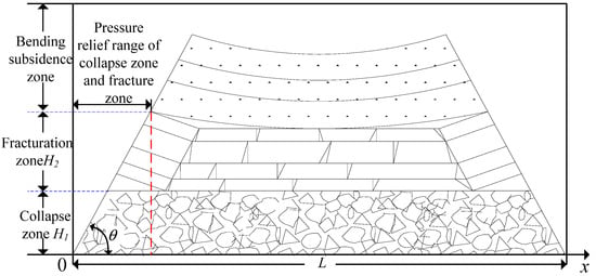
Figure 1.
Structure and distribution characteristics of “three zones”.
When the roof collapse angle is certain, the mining height increases and the height of the collapse zone fissure zone increases, resulting in an increase in the length of the trapezoidal waistline, which corresponds to an increase in the recovery distance of the stress in the goaf. At the same time, the extent of the collapse zone increases, resulting in a change in compression characteristics which, in turn, affects the deformation of the bending rock beam and the force distribution of the bending and sinking zone on the extraction zone. By controlling the extent of the vertical three zones, the mining height adjusts the stress distribution in the extraction zone.
2.1.2. Analysis of the Effect of Height Adjustment on Pressure Relief by the Protected Layer
The transfer of the stress distribution in the bottom plate determines the stress characteristics of the protected layer [35], and the stress distribution in the goaf during the workface advance has the characteristics of spatial and temporal evolution. When the mining enters the full mining stage, the range of the unloading zone and stress recovery zone in the goaf is stable and evolves forward [36]. The main role in the unloading of the protected layer is the extent of the unloading zone in the goaf. The mining height adjusts the stress distribution in the goaf to unload the protected layer, which essentially changes the extent of the unloading zone.
2.2. Calculation Model of Stress Distribution in Goaf with Different Mining Heights
2.2.1. Calculation of the Forces Acting on the Goaf from the Fracture Zone and Collapse Zone
Based on the aforementioned analysis, a trapezoidal profile is selected to calculate the force of the collapse zone and the fracture zone on the goaf. Combined with the coordinate axes shown in Figure 1, the force of each sub-zone on the bottom plate is calculated as Equation (1).
where, is the rock capacity, kN/m3; H1 is the extent of the collapse zone, m; H2 is the extent of the fissure zone, m; is the angle of collapse of the roof rock, °; L is the length of the extraction zone, m; and p is the stress transmitted by the bending and sinking zone.
2.2.2. Calculation of the Forces acting on the Goaf from the Curved Sinking Zone
Based on the aforementioned analysis, the calculation of the force of the curved sink zone on the goaf is simplified to the calculation of the force of the rock beam on the bedding layer in the elastic foundation beam model, and a mechanical analysis model is established, as shown, in Figure 2. The collapsed rock support area is x > 0, and x < 0 is the un-collapsed rock support area outside the collapse line.
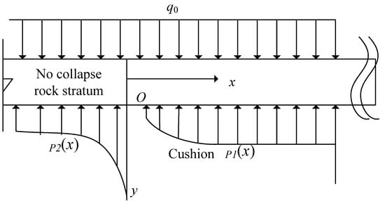
Figure 2.
Bending rock beam stress model.
The bedding beneath the rock beam is regarded as an elastic medium. At this time, the rock beam is supported by two parts, the unbroken rock of the bedding in front of the workings and the broken rock in the goaf. The bedding beneath the curved rock beam is approximated to satisfy the Winkler foundation assumption, i.e.,
where k is the foundation factor, related to the bedding below the rock beam; y is the vertical displacement of the bending rock beam; p is the reaction force generated by the bedding on the bending rock beam, equal to the stress transferred from the bending rock beam to the base plate:
where and are the support force of the foundation on the bent rock beam, kN; is the deflection of the bent rock beam within the goaf, m; is the deflection of the bent rock beam in front of the workings, m; is the foundation factor of the collapsed rock in the goaf, determined by the distribution of the collapse zone; is the foundation factor of the un-collapsed rock below the rock beam, determined by the nature of the rock formation.
p = −ky
The collapsed and fractured rocks are assumed to collapse and expand upon contact with the curved subsidence rock beams. Based on the equation for the change in deflection of the elastic foundation beam under a uniform load [37], the stress transferred from the bending rock beam to the goaf is obtained, as in Equation (4):
where , , q0 is the self-weight of the rock in the bending and sinking zone, MPa. EI is the bending stiffness of the rock beam section, N·m2.
2.3. Stress Distribution Pattern of the Goaf affected by Mining Height
2.3.1. Stress Distribution Pattern of Collapse Zone and Fracture Zone in Goaf under the Influence of Mining Height
Through the existing empirical formula, it can be observed [38] that the increase in mining height corresponds to the increase in the range of the collapse zone and the fissure zone, corresponding to the increase in H1 and H2 in Equation (1), and the increase in the stress recovery distance in the goaf.
2.3.2. Stress Distribution Pattern in the Bending and Sinking Zone of Goaf under the Influence of Mining Height
The compression characteristics of the collapse zone in the goaf can be described by Salamon’s empirical formula [39] with the workings extraction; the collapsed rock layer fills the goaf, and the collapse zone crushed and expanded rock block support force is:
where Ff is the support force of the crushed and expanded rock mass, N; E0 is the initial tangential modulus, MPa; is the strain and is the maximum line strain.
The maximum strain on the crushed rock in the collapse zone, , can be calculated using Equation (6), where the upper load is considered to be infinite and the crushed rock in the collapse zone is completely compacted:
where B is the coefficient of volumetric swelling.
Based on the nature of the rock in the goaf, the results of a large number of indoor experimental studies are fitted to E0 and the initial tangential modulus is derived as in Equation (7) [39]:
where is the uniaxial compressive strength of the rock mass, MPa.
The strain is the ratio of the compressive deformation to the total height of the collapsed rock mass:
where hy is the collapse zone compression, m; H1 is the collapse zone rock height, m, which can be calculated by empirical formula; hm is the mining height, m.
One can combine Equations (6)–(8) with Equation (5) to obtain the reaction force of the compressed rock formation.
According to Equation (8), when the mining height is , the corresponding volume swelling factor B can be expressed as:
Equation (10) is carried over into Equation (9) to obtain the force-strain relationship (11) of the different mining heights. Based on Equation (11), the compression force and strain relationship for the collapse zone at different mining heights can be obtained, and then the foundation factor ki can be obtained.
2.3.3. Theoretical Analysis of Stress Distribution in Goaf Affected by Mining Heights
Based on the given formulae, the stress distribution in the goaf corresponding to different mining heights is calculated separately by selecting the mining of the thin coal seam protection layer of non-full coal in the Hongyang San Mine as the engineering background.
- ①
- Background of the project
At present, the mine mainly mines the No.7 and No.12 coal seams. As the mine has entered the deep mining area to the south, the No.7 coal seam is at risk of protrusion and it is proposed to adopt the method of mining the No.3 coal seam to protect the No.7 coal seam to decompress and eliminate the protrusion. The distribution and physical and mechanical parameters of the rocks above the roof of the No.3 coal seam are shown in Table 1.

Table 1.
Physical and mechanical parameters of rock formation in Hongyang No. 3 Mine.
- ②
- Calculation of stress distribution patterns in the collapse zone and fracture zone corresponding to the goaf
- a.
- Height estimation of collapse zone and fracture zone
The mining heights of 1 m, 1.5 m, 2 m, 2.5 m and 3 m are analyzed, respectively. Based on the physical and mechanical properties of the above rock formations, the compressive strength of the top slab is averaged and the average compressive strength is calculated to be about 22 MPa. Based on the empirical formula [38], the distribution range of the corresponding collapse zone and fracture zone under different mining height conditions is obtained, as shown in Table 2.

Table 2.
The distribution range of “three zones”.
- b.
- Analysis of the extent of pressure relief in the goaf
Combined with the field observation data, the rock collapse angle is 60°. According to the height of the fissure zone, the pressure-relief range of the fissure zone is 14 m, 18 m, 20 m, 22 m and 24 m, respectively, under different mining height conditions of 1~3 m.
- ③
- Calculation of the stress distribution law in the goaf corresponding to the bending and sinking zone
- a.
- Foundation coefficient ki analysis of the collapse zone
According to the calculation Formula (10) of the coefficient of fracture expansion within the collapse zone, the coefficient of fracture expansion of the collapse zone as a bedding layer is shown in Table 3.

Table 3.
The bulking coefficient of falling zone at different mining height.
The average compressive strength of the overburden rock, , is added to Equation (11) to obtain the stress–strain relationship curve for the collapse zone under different mining height conditions, as shown in Figure 3.
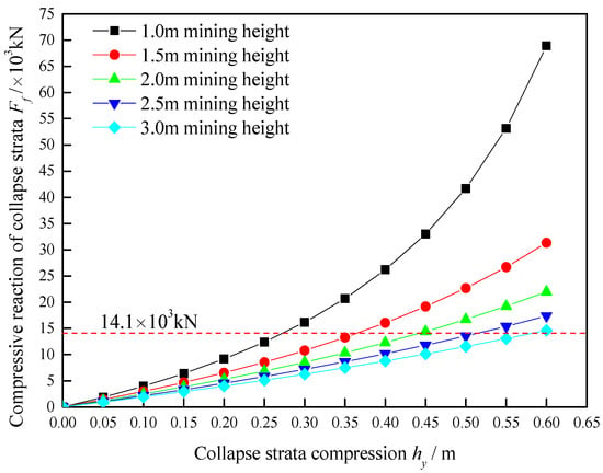
Figure 3.
Compression deformation characteristics of falling zone with different mining height.
It can be seen from the curve in Figure 3 that, with the increase in mining height, the stress–strain curve of the compression of the collapse zone gradually converges in the initial stage. Based on the thickness of the rock layer above the collapse zone, the self-weight stress of the rock layer above the collapse zone is estimated to be 14.1 MPa, which corresponds to a load-per-unit area of 14.1 × 10³ kN. The stress-deformation curves of different mining heights corresponding to this stress value are selected as tangents in Figure 3 to obtain the foundation coefficient ki.
- b.
- Analysis of foundation coefficients in the area of unbent rock kj
- Determination of the bending rock beam
According to the key layer theory, the key layer is the main load-bearing structure controlling the synergistic deformation of the rock formation; the bending rock beam above the elastic foundation can be determined using the key layer theory. The key layer that can be used as the bending rock beam is the key layer whose layer level is higher than the range of the fracture zone, so the bending rock beam is determined as the key layer 2 in Table 1.
- Foundation coefficients in the area of unbroken rock
Considering the deformation range of the rock beam, the corresponding siltstone and mudstone below the sub-critical layer are selected as its bedding layer. Based on the elastic modulus and thickness of the siltstone and mudstone, the foundation coefficient is determined to be 4.29 GPa/m3.
- c.
- Calculation of stress distribution in the extraction zone of the bending and sinking zone
Based on the aforementioned analysis, the final calculation parameters of the stresses transferred from the rock beam to the goaf for different mining heights are obtained, as shown in Table 4.

Table 4.
Calculation parameters.
Combining the parameters in Table 4, Equation (4) is used to calculate the forces on the foundation below in the region x > 0 for the bending rock beam, as shown in Figure 4.
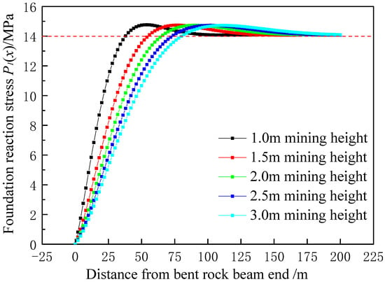
Figure 4.
Force distribution of bending rock beam at different mining heights.
2.3.4. Determination of the Stress Distribution Law in the Goaf
- ①
- Determination of the pressure-relief area in the goaf
It can be seen from Figure 4 that, during the downward transfer of stress in the bending and sinking zone due to the bearing capacity of the bending rock beam itself, some areas’ transfer stress values are smaller than the load above, and these areas constitute the unloading area of the goaf. The final pressure-relief area of the extraction zone can be determined by summing up the pressure-relief area of the collapse zone and the fracture zone with the pressure-relief area of the bending and sinking zone, as shown in Figure 5.
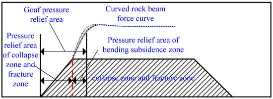
Figure 5.
Determination of pressure relief area in goaf.
The final range of the vertical three zones’ pressure-relief area is shown in Table 5.

Table 5.
Distribution of pressure-relief area in goaf.
- ②
- Determination of the stress distribution law in the goaf
The aforementioned analysis gives the stress recovery distance in the extraction zone. The stress distribution in the quarry can be approximately divided into five parts, as shown in Figure 6, where K is the stress concentration coefficient and γH is the original rock stress, MPa. Based on the stress recovery distance, the stress distribution law in the extraction zone can be obtained, i.e., ④ and ⑤, where the pressure-relief area in the extraction zone in Table 5 corresponds to ④ in Figure 6a. Calculation of the stress distribution of the protected layer requires the distribution of the support pressure, which needs to be calculated for the remaining three parts of the stress distribution.
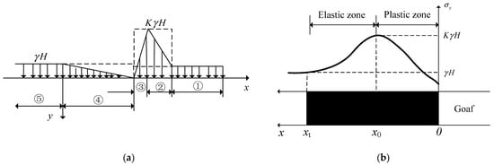
Figure 6.
Working face-bearing pressure distribution. (a) Bearing pressure distribution characteristics; (b) distribution of the elastic–plastic zone in front of the working surface.
The support pressure in front of the working face can be calculated by the limit balance method [40], as shown in Equations (12) and (13):
where x0 is the extent of the plastic zone Figure 6b, corresponding to ③ in Figure 6a, m; xt is the extent of the elastic zone Figure 6b, corresponding to ② in Figure 6a, m; K is the stress concentration factor above the working face; N0 is the support force in the vertical direction of the coal wall, MPa; γH is the self-weight stress in the overlying rock, MPa; f is the interlayer friction factor.
The above calculation gives the calculation method for the support pressure of the working face but, for the unmined working face, the stress concentration coefficient cannot be determined and cannot be calculated directly by Equations (12) and (13). Based on the calculation model of load conservation in the overlying rock layer of the quarry [41], the total stress reduction in the unloading area within the goaf of Figure 6 is equal to the total stress increase in the area in front of the working face, and Equation (14) can be obtained as follows:
Simplification gives:
where Lc is the stress recovery distance of the goaf, m, as in Table 5, the pressure-relief area of the goaf.
The joint vertical (12) (13) (15) to obtain Equation (16) is:
Equation (16) has only K as an unknown and can be solved. Also, the equation is a transcendental equation and, after bringing in the rest of the known numbers, the numerical solution can be used to find the value of K. Bringing the obtained K values into Equations (12) and (13), the x0 and xt values can be obtained, i.e., the range of ② and ③ in Figure 6, and, thus, the whole support pressure distribution can be obtained.
The base parameters of the coal seam , , , N0 = 2.75 MPa, and the stress recovery value Lc in the goaf corresponding to different mining heights hm, are brought into Equation (16) to obtain the support pressure distribution characteristics corresponding to different mining heights, as shown in Table 6.

Table 6.
Bearing pressure distribution of different mining height.
3. Results
3.1. Calculation of Stresses at Different Levels of the Substrate
The stress distribution in the bottom slab can be calculated by the semi-infinite plane elastic theory for the unloading values at 5 m, 10 m, 20 m, 30 m, 40 m, 48 m and 60 m below the bottom slab 29, and the results are shown in Figure 7.
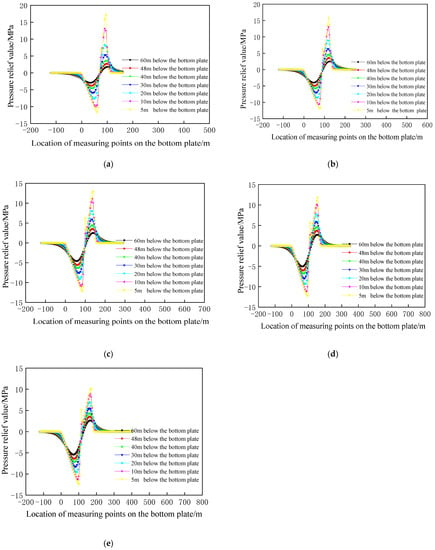
Figure 7.
Distribution of floor pressure relief value at different mining heights: (a) mining height 1 m; (b) mining height 1.5 m; (c) mining height 2 m; (d) mining height 2.5 m; (e) mining height 3 m.
It can be seen from Figure 7, under different mining height conditions, the increase in mining height is beneficial to the increase in the pressure-relief range and the pressure-relief value, while the increase in the mining height up to 2 m reduces the effect of the pressure-relief range and the pressure-relief value as the mining height increases.
Based on the data in Figure 7, the distribution of the maximum pressure-relief value of the rock layers, with different layer spacing below the bottom slab corresponding to different mining heights, is calculated, as shown in Figure 8. With the increase in the mining height, the maximum pressure-relief values of the different seams gradually approach each other and, the closer the seams are to the mined coal seam, the more obvious it is that the maximum pressure-relief values tend to be consistent with the increase in the mining height.
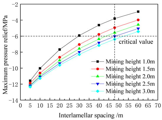
Figure 8.
Mining height corresponds to the maximum pressure-relief value of different interlayer spacing.
3.2. Determination of Minimum Layer Spacing
The normal strain in the coal seam before unloading of the protected layer is [14,42] Equation (17):
The normal strain after decompression is Equation (18):
The amount of strain change resulting from unloading is Equation (19):
where , , is the original rock stress before unloading; MPa; , , , is the stress after unloading the protected coal seam, MPa; is the strain in the starting state; is the strain generated by unloading the coal seam; is the strain generated by the coal rock body after unloading; H is the depth of burial of the unloaded coal seam, m; is the Poisson’s ratio; E is the modulus of elasticity, GPa; is the lateral pressure coefficient; is the capacity of the coal rock body, kN/m.
The coal seam unloading pressure expansion reaching 3‰ is used as the basis for determining the effectiveness of protection, and the expansion deformation is determined by Equation (20).
Substituting Equations (17) and (19) in Equation (20) and introducing the relationship between the vertical stress after decompression shows that the vertical stress before decompression when protecting the effective critical state (21) is:
According to the report of the physical and mechanical parameters of coal rocks in the Hongyang 3 mine, the No.7 coal E = 2.0 GPa, = 0.28, , H = 800 m, and the protected layer No.7 coal = 20 MPa, the critical residual vertical stress value = 14.03 MPa is calculated by using Equation (21) to make the protected layer reach 3‰ deformation. The corresponding unloading stress value should be greater than 5.97 MPa to achieve effective protection. The distance between coal seam No.3 and coal seam No.7 is 48 m, as shown in the intersection of the vertical lines in Figure 8. The unloading stress value is 3.8 MPa for a mining height of 1 m, 4.9 MPa for a mining height of 1.5 m, 5.56 MPa for a mining height of 2 m and 6.02 MPa for a mining height of 2.5 m. Therefore, the minimum design mining height under the current conditions is 2.5 m, the thickness of the thin coal seam at this stage is 1 m, and a 1.5 m thickness of the top or bottom slab rock should be mined.
3.3. Verification of Calculation Results
The mining face with a mining height of 2.5 m was designed on site. In order to verify the effect of pressure-relief protection, the holes were drilled upwards in the bottom extraction lane of the protected layer South I 701 working face, and a deep base point displacement meter was installed to test the amount of expansion deformation. To test the evolution of the expansion deformation law of the South I 701 working face during the advancement of the No.3 coal seam South I 301 working face, the location of the measurement point is shown in Figure 9.
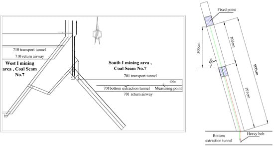
Figure 9.
Expansion deformation measurement arrangement.
The thickness of the coal seam at the South I, 701 working face is 3 m, and the deep base point displacement gauges are installed at the top and bottom plates of the coal seam, respectively. The base point displacement of the top and bottom plates is obtained by observing the length of the line of measurement from the heavy hammer to the inside of the roadway, and the difference between the two base-point displacements is made to obtain the expansion volume. The expansion deformation volume is further obtained, as shown in Figure 10. The test results show that the use of the 2.5 m mining height plays an effective role in protecting the protected layer below.
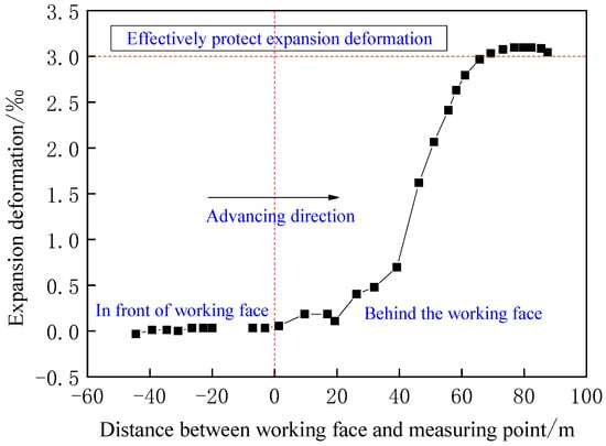
Figure 10.
Evolution law of expansion deformation.
4. Discussion
Based on Equation (21), the effective value of the pressure relief can be calculated when the distance between the coal seam and the mined seam is 10 m, 20 m, 30 m, 40 m and 50 m, respectively, with the parameters shown in Table 7.

Table 7.
Calculation of effective pressure relief value for different interlayer spacing.
From the calculation results, under the conditions of 10~50 m layer spacing, it can be seen that the critical value of pressure relief for the corresponding protected layer to reach effective protection is close, taking 5.97 as the critical value and making a horizontal line in Figure 8. The intersection of the horizontal line and the curve is the critical effective protection layer spacing corresponding to different mining heights, as shown in Figure 11.
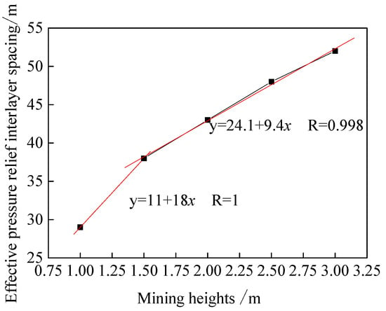
Figure 11.
Effective pressure relief interlayer spacing for different mining heights.
According to the data in Figure 11, when the mining height is varied from 1 m to 3 m, there is a linear relationship between the mining height and the effective layer spacing, with a sudden change at 1.5 m. The relationship between the mining height and the effective layer spacing during the variation from 1 m to 1.5 m conforms to the equation y = 11 + 18x. When the mining height is greater than 1.5 m, it conforms to the equation y = 24.1 + 9.4x. This phenomenon shows that, with the increase in the mining height, the unloading effect on the protected layer at the same layer spacing tends to be consistent, but the effective unloading layer can be extended. Meanwhile, in Figure 6 and Figure 7 of the paper [43], numerical simulations are used to analyze the permeability of the protected layer under different mining heights and layer spacing conditions. The obtained critical effective layer spacing shows the same linear relationship with the mining height, which is similar to the critical effective layer spacing pattern corresponding to the mining height obtained in this study.
5. Conclusions
The selection of the mining height is the core issue in the formulation of the mining plan for the non-full coal protective layer. This paper creatively proposes a quantitative calculation method of the pressure-relief value of the protected layer, corresponding to different mining heights, which provides a basis for the formulation of the mining plan of the protective layer.
(1) The relationship between the mining height and the stress distribution in the lower protected layer is constructed. The mining height affects the distribution range of the “vertical three zones”. The stresses acting on the goaf are different for different ranges of the vertical three zones, which lead to different distribution of the support pressure at the working face and eventually leads to different stress distribution in the protected layer. By changing the height of the collapse zone and the fracture zone, the mining height affects the scope of pressure relief in the extraction zone. Changing the compression characteristics of the collapse zone affects the scope of pressure relief in the extraction zone of the bending and sinking zone.
(2) A model for calculating the stress distribution of the vertical three zones acting on the goaf is established, and the pressure-relief range of the goaf is obtained. The collapse zone and the fracture zone are self-weight stresses. The bending and sinking zone can be calculated by the elastic foundation beam model, and the collapse zone is an elastic foundation. The formulae for calculating the foundation coefficient of the collapse zone with the mining height as the variable are obtained, and the corresponding foundation coefficients are 0.0587 GPa/m3, 0.0158 GPa/m3, 0.00851 GPa/m3, 0.00554 GPa/m3 and 0.00392 GPa/m3 when the mining height changes from 1 m to 3 m with a gradient of 0.5 m. The coefficients of the bending and sinking zone first decrease and then converge, and the unloading range of the bending and sinking zone first increases and then converges. The corresponding stress recovery areas in the mining hollow area are 50 m, 72 m, 84 m, 94 m and 102 m during the 0.5 m gradient change of mining height from 1 m to 3 m.
(3) The calculation method of the working face support pressure is proposed. Using the upper protection layer of the Hongyang 3 mine as the engineering background, the support pressure distribution law corresponding to the change of mining height from 1 m to 3 m with a 0.5 m gradient is calculated.
(4) The stress distribution law of the bottom plate at different layer spacing corresponding to the mining height is obtained. The critical value of pressure discharge when protection is effective is proposed. The corresponding critical pressure discharge value is 5.97 MPa for effective pressure discharge of the No.7 coal seam, and the corresponding minimum mining height of the No.3 coal seam is 2.5 m. When the layer spacing is certain and the mining height changes from 1 m to 2 m, the increase in mining height is beneficial to the increase in the pressure discharge range and the pressure discharge value. When the mining height continues to increase from 2 m, with the increase in the mining height, the effect of increasing the pressure discharge range and the increased effect in the pressure discharge value tends to be the same. However, the increase in mining height can extend the critical layer spacing for effective pressure relief, and there is a linear relationship between mining height and the critical layer spacing for effective pressure relief.
Author Contributions
Conceptualization, Z.S. and D.Y.; Methodology, Z.S. and D.Y.; Validation, S.F. and J.H.; Investigation, Z.S.; Data Curation, D.Y. and B.Q.; Writing—Original Draft Preparation, Z.S.; Writing—Review and Editing, Z.S. and D.Y; Visualization, J.H.; Supervision, W.S.; Project Administration, Z.S.; Funding Acquisition, Z.S.; Investigation, D.Y.; Resources, S.F. All authors have read and agreed to the published version of the manuscript.
Funding
This research was funded by National Natural Science Foundation of China, grant numbers 52004118 and 51874166; Liaoning Technical University, grant number LNTU20TD-11; Department of Education of Liaoning Province, grant number LJ2020QNL009.
Institutional Review Board Statement
Not applicable.
Informed Consent Statement
Not applicable.
Data Availability Statement
The data are contained within the article.
Conflicts of Interest
The authors declare no conflict of interest.
References
- Zhang, M.J.; Fan, H.J.; Tian, J.J.; Lu, K.P. Study on outburst prevention effect of mining in long distance and ultra thin underneath protective seam. J. Coal Sci. Technol. 2017, 45, 67–72+83. [Google Scholar] [CrossRef]
- Jiang, F.X.; Liu, Y.; Liu, J.; Zhang, M.; Du, J.P.; Sun, W.S.; Zhang, W.P. Pressure-releasing mechanism of local protective layer in coal seam with rock burst. Chin. J. Geotech. Eng. 2019, 41, 368–375. [Google Scholar]
- Brandt, J.; Sdunowski, R. Gas drainage in high efficiency workings in German Coal mines. In Proceedings of the 2007 China (Huainan) International Symposium on Coal Gas Control Technology, Huainan, China, 25–27 October 2007; pp. 22–29. [Google Scholar]
- Ren, W.G.; Zhou, H.W.; Xue, D.J.; Wang, L.J.; Rong, T.L.; Liu, J.F. Mechanical behavior and permeability of coal and rock under strong mining disturbance in protected coal seam mining. J. China Coal Soc. 2019, 44, 1473–1481. [Google Scholar] [CrossRef]
- Wang, L.; Lu, Z.; Chen, D.P.; Liu, Q.Q.; Chu, P.; Shu, L.Y.; Barkat, U.; Wen, Z.J. Safe strategy for coal and gas outburst prevention in deep-and-thick coal seams using a soft rock protective layer mining. J. Saf. Sci. 2020, 129, 104800. [Google Scholar] [CrossRef]
- Pang, L.L.; Xu, X.F.; Si, L.; Zhang, H.; Li, Z.K. Analysis of prevention mechanism of upper protective seam mining on rock rockburst induced by thick conglomerate. Rock Soil Mech. 2016, 37, 120–128. [Google Scholar] [CrossRef]
- Tu, Q.Y.; Cheng, Y.P. Stress evolution and coal seam deformation through the mining of a remote upper protective layer. Energy Sources Part A Recovery Util. Environ. Eff. 2019, 41, 338–348. [Google Scholar] [CrossRef]
- Zhang, C.; Tu, S.; Zhang, L. Mining Thickness Determination of Upper and Lower Protective Coal Seam in Pressure Relief Mining. Geotech. Geol. Eng. 2019, 37, 1813–1827. [Google Scholar] [CrossRef]
- Zhang, M.; Shimada, H.; Sasaoka, T.; Matsui, K.; Dou, L.M. Evolution and effect of the stress concentration and rock failure in the deep multi-seam coal mining. Environ. Earth Sci. 2014, 72, 629–643. [Google Scholar] [CrossRef]
- Sun, Q.; Zhang, J.X.; Zhang, Q.; Yin, W.; Germain, D. A protective seam with nearly whole rock mining technology for controlling coal and gas outburst hazards: A case study. Nat. Hazards 2016, 84, 1793–1806. [Google Scholar] [CrossRef]
- Liu, Y.Z.; Zhang, Q.; Zhang, J.G.; Quan, K.; Wei, S.X. Theoretical research on protective seam mining in full rock stratum and engineering application. J. Min. Saf. Eng. 2018, 35, 146–154. [Google Scholar] [CrossRef]
- Cheng, X.; Zhao, G.M.; Li, Y.M.; Meng, X.R.; Liu, Z.H.; Ma, H.F.; Yuan, B.Q. Evolution of overburden mining-induced fractured zone and pressure-relief gas drainage in soft rock protective seam. J. Min. Saf. Eng. 2020, 37, 533–542. [Google Scholar] [CrossRef]
- Li, J.H.; Xu, Y.C.; Xie, X.F.; Yao, Y.L.; Gao, Y.B. Influence of mining height on coal seam floor failure depth. J. China Coal Soc. 2015, 40, 303–310. [Google Scholar] [CrossRef]
- Liang, B.; Shi, Z.S.; Jiang, F.L.; Ma, W. Research on protection result of extra-thin protective coal seam mining. China Saf. Sci. J. 2015, 25, 17–22. [Google Scholar] [CrossRef]
- Li, D.Q. Mining thin sub-layer as self-protective coal seam to reduce the danger of coal and gas outburst. Nat. Hazards 2014, 71, 41–52. [Google Scholar] [CrossRef]
- Wang, H.F.; Cheng, Y.P.; Yuan, L. Gas outburst disasters and the mining technology of key protective seam in coal seam group in the Huainan coalfield. Nat. Hazards 2013, 67, 763–782. [Google Scholar] [CrossRef]
- Cheng, X.; Zhao, G.M.; Li, Y.M.; Meng, X.R.; Tu, Q.Y. Key technologies and engineering practices for soft-rock protective seam mining. Int. J. Min. Sci. Technol. 2020, 67, 763–782. [Google Scholar] [CrossRef]
- State Administration of Coal Mine Safety. 2019 New Edition of Detailed Rules for Prevention and Control of Coal and Gas Outburst; Coal Industry Press: Beijing, China, 2019; pp. 43–45.
- Yu, B.F. Theoretical aspects of the protective coal seam. J. China Coal Soc. 1980, 4, 36–43. [Google Scholar]
- Liu, H.Y.; Cheng, Y.P.; Zhao, C.C.; Zhou, H.X.; Zhang, Z.P. Classification and Judgment Method of the Protective Layers. J. Min. Saf. Eng. 2010, 27, 468–474. [Google Scholar]
- Chen, Y.L.; Wu, H.S.; Zhang, M.W.; Wu, Y.; Zhang, H.Q.; Zhang, G.M. Research on the upper protective coal seam mining effect induced by coal thickness and interburden rock properties. J. Min. Saf. Eng. 2016, 33, 578–584. [Google Scholar] [CrossRef]
- Lu, S.Q.; Cheng, Y.P.; Wang, H.F.; Wang, L.; Li, W.; Mou, J.H. Numerical simulation research on the Hongling Coal Mine’s minimum mining thickness of upper protective layer. J. China Coal Soc. 2012, 37, 43–47. [Google Scholar] [CrossRef]
- Liu, H.B.; Cheng, Y.P.; Song, J.C.; Shang, Z.J. The change and distribution law of outburst coal seam permeability induced by drilling an extra-thin protective coal seam. J. China Coal Soc. 2010, 35, 411–416. [Google Scholar] [CrossRef]
- Hui, G.L.; Song, J.H. Parameter Calculation Analysis of the Coal Rock Dynamical Evolution of the Deep Protective Seam Mining. Saf. Coal Mines 2013, 44, 168–171. [Google Scholar] [CrossRef]
- Majkherchik, T.; Gajko, G.I.; Malkowski, P. Deformation process around a heading investigation when front of longwall face advancing. Ugol 2002, 11, 27–29. [Google Scholar]
- Dychkovskyi, R.; Shavarskyi, I.; Saik, P.; Lozynskyi, V.; Falshtynskyi, V.; Cabana, E. Research into stress-strain state of the rock mass condition in the process of the operation of double-unit longwalls. Min. Miner. Depos. 2020, 14, 85–94. [Google Scholar] [CrossRef]
- Slashchov, I.; Shevchenko, V.; Kurinnyi, V.; Slashchova, O.; Yalanskyi, O. Forecast of potentially dangerous rock pressure manifestations in the mine roadways by using information technology and radiometric control methods. Min. Miner. Depos. 2019, 13, 9–17. [Google Scholar] [CrossRef]
- Iordanov, I.; Buleha, I.; Bachurina, Y.; Boichenko, H.; Dovgal, V.; Kayun, O.; Kohtieva, O.; Podkopayev, Y. Experimental research on the haulage drifts stability in steeply dipping seams. Min. Miner. Depos. 2021, 15, 56–67. [Google Scholar] [CrossRef]
- Snihur, V.; Bondarenko, V.; Kovalevska, I.; Husiev, O.; Shaikhlislamova, I. Optimization solution substantiation for resource-saving maintenance of workings. Min. Miner. Depos. 2022, 16, 9–18. [Google Scholar] [CrossRef]
- Jin, J.; Qin, Z.; Lü, X.; Liu, T.; Zhang, G.; Shi, J.; Zuo, S.; Li, D. Rheology control of self-consolidating cement-tailings grout for the feasible use in coal gangue-filled backfill. Constr. Build. Mater. 2022, 316, 125836. [Google Scholar] [CrossRef]
- Wang, X.B.; Zhu, M.Z.; Cen, Z.H. Simulation on strata motion of S6–8 working face in Changcun coal mine with continuum-discontinuum method. J. Saf. Sci. Technol. 2020, 16, 82–87. [Google Scholar]
- Zhang, H.T.; Wen, Z.H.; Yao, B.H.; Chen, X.Q. Numerical simulation on stress evolution and deformation of overlying coal seam in lower protective layer mining. Alex. Eng. J. 2020, 59, 3623–3633. [Google Scholar] [CrossRef]
- Liu, S.J.; Lin, B.Q.; Gao, J.; Hao, Z.Y.; Li, Q.G.; Meng, J. Similar Simulation of Fracture Deformation in Overlying Coal and Rock in Far-Distance-Lower-Protective-Layer Mining. J. Min. Saf. Eng. 2011, 28, 51–55+60. [Google Scholar]
- Huang, Q.X.; Xia, X.G. Division of “four zones” in mining strata and surface movement. J. Min. Saf. Eng. 2016, 33, 393–397. [Google Scholar] [CrossRef]
- Shi, Z.S.; Liang, B.; Sun, W.J. Study on floor pressure-relief evolution characteristics at goaf stress adjustment stage. J. Min. Saf. Eng. 2019, 36, 51–58. [Google Scholar] [CrossRef]
- Chen, R.Z.; Tu, Q.Y.; Cheng, Y.P.; Liu, Q.F. Analysis of the fracture spatial-temporal development process of underlying coal (rock) through the mining of a close upper protective layer. J. Xi’an Univ. Sci Technol. 2018, 38, 71–78. [Google Scholar] [CrossRef]
- Long, Y.Q. Calculation of Beam on Elastic Foundation; People’s Education Press: Beijing, China, 1981; pp. 21–36. [Google Scholar]
- State Administration of Work Safety; State Administration of Coal Mine Safety; State Energy Administration; State Railway Administration. Code for Coal Pillar Reservation and Coal Pressure Mining of Buildings, Water Bodies, Railways and Main Shafts and Roadways; Coal Industry Press: Beijing, China, 2017; pp. 231–255.
- Pappas, D.M.; Mark, C. Behavior of Simulated Longwall Gob Material; United States Department of the Interior Bureau of Mines: Washington, DC, USA, 1993. [Google Scholar]
- Jin, Z.M.; Wei, J.P.; Jin, W.X. Distributive characterisic of front abutment pressure in top-coal caving face. J. Taiyuan Univ. Technol. 2001, 2, 216–218. [Google Scholar] [CrossRef]
- Wang, W.X. Cover Stress Re-Establishment and Its Permeability Evolution in Mining-Induced Fracture Rock Mass; China University of Mining and Technology: Xuzhou, China, 2014. [Google Scholar]
- Wu, R.L. Study on the Scope of the “Three Zones” of Gas Pressure Relief and Extraction in Coal Seam Group Mining; China University of Mining and Technology: Xuzhou, China, 2011. [Google Scholar]
- Zhang, C. Coupling Mechanism of Stress-Fracture-Flow in High Gas Coal Seam Group and Its Impact on Pressure Relief Extraction; China University of Mining and Technology: Xuzhou, China, 2017. [Google Scholar]
Publisher’s Note: MDPI stays neutral with regard to jurisdictional claims in published maps and institutional affiliations. |
© 2022 by the authors. Licensee MDPI, Basel, Switzerland. This article is an open access article distributed under the terms and conditions of the Creative Commons Attribution (CC BY) license (https://creativecommons.org/licenses/by/4.0/).