Abstract
Hybrid Systems in microgrid applications have gained relevance in power flow management in the context of the worldwide power grids transformation. Successfully integrating several technologies of micro resources and storage systems is a key component of microgrid applications. To address this issue, dc-bus signaling (DBS) is proposed here and used as a distributed decentralized control strategy in which the control nodes, as the generation sources/storage interface converters, induce DC bus voltage-level changes to communicate with the other control nodes. The DC bus voltage thresholds are identified and assigned to each converter to trigger the point at which it begins discharging or charging for six different DC Nano Grid (DCNG) configurations, thereby integrating both conventional and unconventional storage systems. Several test cases have been analyzed to verify the effectiveness of the proposed control logic.
1. Introduction
Nowadays, the electrical energy cycle from production to consumption has been redefined with the increasing awareness of the importance of reducing the environmental impact of electricity production in accordance with global eco-sustainable policies. Through widespread and technological improvement of the DGs-Res (Distributed Generation based on Renewable Energy Resources) e.g., PV and Wind, locally generated electricity is able to cope with local electrical demand at the same point/time. However, the intermittency of these types of resources is often cited as a barrier to their large-scale integration into the grid [1]. In fact, wind and solar power are characterized by rapid and less predictable fluctuations over time scales from minutes to hours [1,2]. Emerging analytical techniques account for the uncertainties associated with solar irradiance, wind speed, demand, and outages of various generating units [1,2,3]. Nevertheless, how to match electrical consumption to DG-Res energy production is the key issue and more technological effort is required to resolve this [4].
Energy Storage systems can be used to create synergies with the local DGs-Res and the role of storage devices is to balance and smooth power sources with power demands [4,5,6,7,8].
Indeed, as for these renewable-energy power source systems, energy storage devices are required to play two major roles: to provide a rapid response to high large power (PV-Peak Power) during times of high PV generation; and to provide large capacity responses to cope with local electrical consumption even when there is no Res-production e.g., for example at night [8]. However, these two roles are difficult to perform by one single storage device, because electric capacitance increases with the storage amount, leading to slow responses. Moreover, increasing the battery pack size will cause increased costs [8]. A Hybrid Energy Storage System (HESS), which allows for the combination of the peculiarities of different energy storage types, can be a solution. The HESS provides the advantage of combining different elements: one of these elements is having high power density i.e., via a supercapacitor and the other is having high energy density i.e., via a flow battery or hydrogen systems [5].
Although an AC system is commonly used for electric power systems and AC Nano Grids are proposed in the literature, a DC-bus system connected with energy storage to balance the power demand and the source power is a major solution for renewable-power-source systems [9,10,11,12,13,14,15,16,17,18]. A DC-bus system is suitable to be used when the source and destination of the energy are both on DC, even though DC-DC level adjustment does occur. Fully shifting to DC can save energy and capital expenditure by eliminating DC-AC and AC-DC conversion losses [10,11].
In this context, integrating HESS can be successfully addressed by the DC Nano Grid (DCNG) system which is described further below. Operating in a grid-connected or in a stand-alone mode, it is capable of simultaneously managing several types of generation sources and different storage system technologies (i.e., Li-Ion, flow battery, supercapacitor, fuel cells with hydrogen technology), as well as the exchange of power flows with the electrical grid to provide ancillary services [4,19]. The fields of DC or AC-bus micro-and nano-grids as distributed control systems have been widely studied [15,18,19,20,21,22,23,24,25,26,27,28,29]. To handle the variety of DGs-Res that are available, a distributed control strategy for islanded single-phase microgrids with hybrid energy storage systems based on power line communications is proposed in [15].
The management and control logic of the DCNG, proposed in this study, is based on the decentralized distributed control concept, which is referred to in the literature as DC Bus Signaling (DBS) [23,24,25,26]. A decentralized control strategy is preferred in that context, since the system becomes independent with respect to a central controller, and unlike a distributed control system, a communication link is not required [23,25]. The DC voltage measured at the common DC bus is the only information exchanged among the units that make up the DCNG, making the DCNG stable in all normal and critical operating conditions. On the other hand, the signaling need could grow due to proliferation of the number of DC devices or by the inclusion of IoT loads in a DCNG and then undermine the DBS technique. A principal converter (also known as a Master Converter), defined per each DCNG configuration and status, regulates the DC bus voltage and characterizes the operation modes. The switching among the different operation modes and the corresponding activation of the appropriate control logic (master or slave) for the converters belonging to the DCNG only depends on the DC bus voltage level. If the number of resources to be managed increases, then a limitation of this control logic is the identification of the aforementioned voltage levels to guarantee the operation of the DCNG at a voltage level of the DC bus that does not differ much from its nominal value.
Furthermore, effective management results in the reduction of the peak power demand, thereby avoiding an overload in the power generation systems. As a result, a reduction in the overall electrical costs can occur for the end-users. Ancillary services (e.g., Active/Reactive power management) can also be managed. DR (Demand Response) programs, Home Automation, and smart meters can act to improve power flow management as well. Finally, the traditional electrical utilities market is changing into a local market managed by an aggregator (PowerCloud model [9]) where the end-users can be Prosumers (both a consumer and a producer) or Prosumages (both a consumer and a producer with a storage system) or Nonsumers (users that are completely self-sufficient), or simply producers. To this end, this paper’s contribution with respect to what is present in the literature [6,18,19,20,21,22,23,24,25,26,27,28,29] is to propose dynamic DC bus voltage thresholds in order to assign the role of the master while considering the real configuration of the DCNG and therefore ensuring that the resources that are needed are actually available without service interruption. Following the same lines of the preliminary work [7], a DBS control of an energy hybrid system integrating several storage technologies is introduced and shown to be effective in power flow management. Moreover, the presented work extends [7] in several aspects:
- Several equivalent models and related dynamic models have been added and their control logics has been implemented for each energy storage system.
- Moreover, the power electronic interface control logic has been implemented. For the DBS logic, new DC bus voltage thresholds were defined.
- New test cases have been analyzed to verify the effectiveness of the proposed control logic.
- The Introduction and the literature review have been completely rewritten. For the literature review, the list of references has been updated and an extensive comparison with works focusing on DBS Strategy has been considered as well.
The paper includes the following five sections. Section 2 introduces the DBS control logic and then describes the DCNG architecture configurations under study. Section 3 illustrates the simulation results. Section 4 summarizes to highlight effectiveness of the proposed control strategy, whereas Section 5 recaps the main conclusions.
2. Materials and Methods
2.1. DBS Control Logic
The proposed DBS control logic is a decentralized control logic based on the definition of two specific roles assigned to the conventional and unconventional storages, as well as the Power Electronic Interface (PEI) and the generation sources in the DCNG under study. The defined roles are: Master and Slave. It is not possible to have more Master roles simultaneously, while more Slaves can act together. The roles activation takes place based on the DC bus voltage value and defining specific voltage thresholds per each asset involved in DBS control. To clarify the roles activation mechanism, let us consider a generic resource present in the DCNG for which the threshold voltages values shown in the Figure 1 have been defined.

Figure 1.
Voltage thresholds definition.
The network is initially assumed to be stable with no active power surplus or deficit and with DC bus voltage equal to 400 V. As you can see in the figure, two voltage thresholds range are defined: the high range is made up of values that are larger than 400 V, while the low range has values less than 400 V. The high range is defined to consider an eventual active power surplus in the DCNG, while the low range for the active power has a deficit. The general lack of time coincidence between production and demand linked to final energy uses is due to the presence in the DCNG of non-programmability resources and their peculiar characteristics. An active power surplus leads to a DC bus voltage increasing, while the DC bus voltage decreases due to an active power deficit.
During the voltage increasing, the DC bus voltage values go toward the High voltage thresholds range. If the voltage is within the high voltage range, then this resource plays the master role.
When a resource takes the master role, its own control sets the resource control current iM at:
If the voltage increasing and becomes greater than 420 V, the resource stops taking the master role and switches to the slave role. The slave resource’s control system sets the current to the current nominal value:
It is easy to replicate the same procedure if the DC bus voltage, starting from 400 V, decreases toward the resource’s Low voltages ranges. The resource takes the Master role if the DC bus voltage value remains within the Low voltages range, while in case of the DC bus voltage being less than 380 V, it stops assuming the master role and plays the slave role. From the previous description, it is clear that the proposed control logic needs voltage thresholds definition for each asset involved in the DBS control process.
It is worth noting that the voltage thresholds definition represents a critical point. Indeed, a wrong choice can lead instability problems for the DCNG management due to unintentional roles activation. Moreover, switching between roles requires a fast control system response to avoid more simultaneous master role activation in the DCNG. To select the voltage thresholds that are suitable for our purposes and test the decentralized control for different resources, several DCNG configurations were considered and simulated to test the DBS control behavior (see Table A1 in Appendix A). The simulation environment used is the Powerfactory DIgSILENT. Per each resource listed in Table A1, the decentralized control logic has been developed as well as the specific dynamic model to characterize the resources behavior. The Table A2, Table A3, Table A4, Table A5, Table A6 and Table A7 in Appendix A show the voltage thresholds per each DCNG configurations. Our idea involved starting using a simple DCNG configuration with just one conventional energy storage type and then increasing the grid complexity step by step adding new conventional and unconventional energy storage systems. The total number of DCNG configurations that were analyzed have been six and in the next subsections, you can find a brief description of each of them.
2.2. NG1 Configuration
A DCNG is a hybrid power supply system with a nominal power that does not exceed 5 kW, which interconnects generation and PV systems and combines heat and power with a Stirling engine or natural gas micro-turbines, fuel cells, energy storage systems (ESSs), and loads on a common DC bus. Among the DCNG loads, it is possible to distinguish between AC electrical loads and critical loads connected to the DC bus using a specific AC/DC converter. Each unit is interfaced to the DC bus using a suitable power converter, which is either DC/DC or DC/AC. The DCNG is interfaced to the electrical distribution grid through a single bidirectional AC/DC converter, called a Power Electronic Interface (PEI) [19]. The first DCNG configuration analyzed is shown in Figure 2.
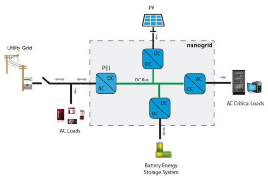
Figure 2.
NG1 Configuration.
The NG1 configuration is composed of:
- A Lithium Battery
- A Photovoltaic system
- Critical Loads
- A Power Electronic Interface (PEI)
The Lithium Battery equivalent model used for the simulation is based on [30]. For the sake of simplicity, the battery lifetime model described in [30] has been neglected. The related Lithium Battery dynamic model implemented in a Powerfactory environment is shown below.
In the Figure 3, the transient parameters responsible for the short (Rt_s, Ct_s) and long-time (Rt_l, Ct_l) constants of the step response are highlighted, while Rs is the series resistor as described in [25]. The parameters Voc, Rs, Rt_s, Rt_l, Ct_s, and Ct_l are SOC dependent [30] and the related functions are implemented in the dynamic model. Based on the configurations of each storage system in the DCNG, a decentralized control model was implemented (see Figure 4).
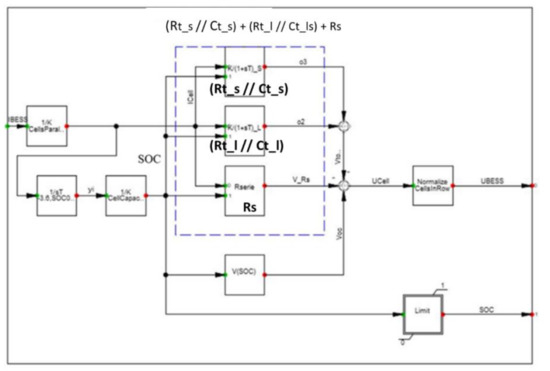
Figure 3.
Lithium Battery dynamic model.
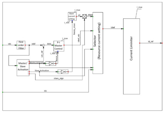
Figure 4.
Decentralized resource control.
The main functionalities shown in Figure 4 are:
- “Master/Slave Activation” defines the resource role (master/slave) based on the DC bus voltage;
- “P-I Master control” calculates the resource’s current, iM (1), during the resource master role;
- “Slave current setting” calculates the resource’s current, iSlave (2), during the resource slave role.
- “Resource current setting” sends the signal to the resource in order to set its current value (i.e., iM or iSlave).
The dynamic behavior of the proposed control is modeled by the DSL (DigSilent Simulation Language) equations written in the blocks pointed out in the Figure 4. By way of example, we propose a small portion of DSL code used in the “Master/Slave Activation” block below.
First of all, the control checks to see whether the DC bus voltage is within high or low ranges threshold range of the resource. For these purposes, two binary signals are defined (ivio_h for the high range and ivio_ for thr low range):
where vdc_hmin and vdc_hmax are the high voltage threshold limits, while vdc_lmin and vdc_lmax are the low threshold limits of the controlled resource.
ivio_h = select(vdc ≥ vdc_hmin. and vdc ≤ vdc_hmax,1,0)
ivio_l = select(vdc ≥ vdc_lmin. and vdc ≤ vdc_lmax,1,0)
Then the next step is check whether the DC bus voltage is above the high range or below the low range of the resources:
ivio_slave = select(vdc > vdc_hmax. or vdc < vdc_lmin,1,0).
The controller has to set the right vdc reference definition according to the DC bus voltage value and the controlled resource. For each resources, we defined a specific vdc reference value. It is clear that the control would have to be very fast to follow the DC bus voltage variations. Thanks to the DSL functionalities, it is possible to tune the signals activation to choose the right values. For sake of simplicity, we neglected the DSL code related to the described stage, but it is worth noting that starting from the DC bus voltage measurement alone, the “Master/slave activation” is able to enable the two signals for the master and slave activation.
Finally, it is worth highlighting that the developed control can work with several different energy storage technologies by operating as a single “logical” system to manage the DC bus voltage.
By contrast, the Power Electronic Interface (PEI) requires a specific decentralized control (see Figure 5).
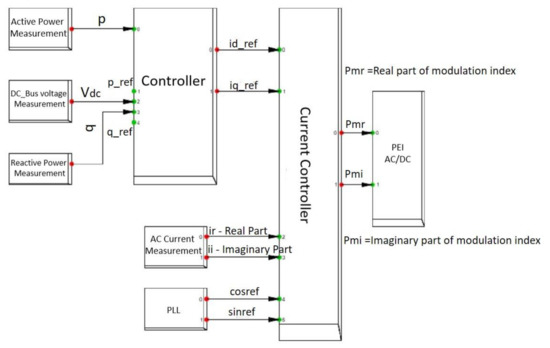
Figure 5.
Decentralized Power Electronic Interface (PEI) control.
The proposed control allows for setting active and reactive power at the inverter AC side terminals starting with a given active power profile, while also considering the option of providing ancillary services to a network operator.
When the DC_Bus voltage is within the PEI’s High voltage thresholds range or Low voltages thresholds range, the PEI takes the master role and starts to regulate the voltage at its DC terminals based on Vref_H or Vref_L (using the PI regulator).
Also for microgeneration resources, it is necessary to define a proper decentralized control (see Figure 6).
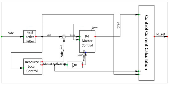
Figure 6.
Decentralized Microgeneration control.
The microgeneration resource takes the master role if the DC BUS voltage value is major and then becomes a specific Vref. The microgeneration is the last resource that can be activated as in the master role. With Master role activation, the Maximum power point tracking (MPPT) is deactivated, thus the provided power by microgeneration decreases. Consequently, the DC BUS voltage value decreases.
The information about the NG1 resources is shown in Table 1, while the simulation results are described in the “Results” section.

Table 1.
NG1 resources informations.
2.3. NG2 Configuration
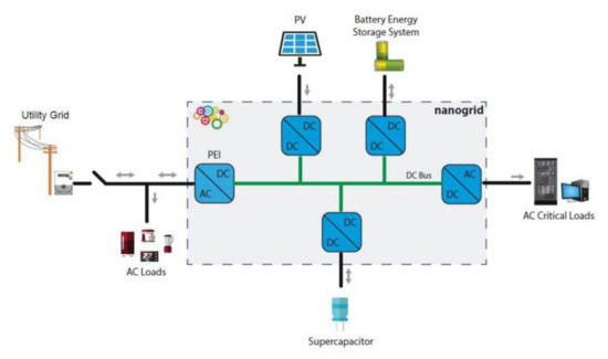
Figure 7.
NG2 Configuration.
Table 2.
NG2 resources information.
In the NG2 configuration, a supercapacitor [31] was added with respect to NG1. This supercapacitor is the master when the Vref = 400 V (see Table A3 in Appendix A). Its role is very important since, starting with a DC BUS voltage equal to 400 V (which means there is neither an active power surplus nor an active power deficit in the grid), it is the first master to be activated due to unbalanced active power.
We chose the supercapacitor as first master to activate for the following reasons:
- It is the fastest storage system;
- It is able to provide a large amount of power in a small period of time.
The equivalent model used to simulate the supercapacitor behavior is shown in Figure 8 while in Figure 9 you can see the model implemented in a Powerfactory environment.
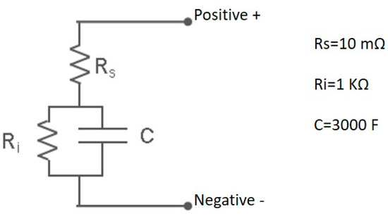
Figure 8.
Supercapacitor Equivalent model.
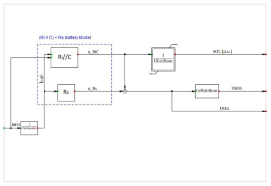
Figure 9.
Supercapacitor dynamic model in Powerfactory.
To obtain a more flexible model, we parameterized the data to the cells number, since the cells number depends on the characteristics of the DC/DC converter that is connected to the supercapacitor.
The NG2 assessment results obtained with the simulation are reported in the “Results” section.
2.4. NG3 Configuration
In this configuration, we added a flow battery as a new form of conventional storage and we studied the DBS control behavior (see Figure 10). Obviously every time a new component is added to the DCNG, it needs a new thresholds definition based on each component involved in the DBS control. The defined thresholds are shown in Table A4 in Appendix A.
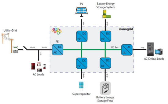
Figure 10.
NG3 Configuration.
Also, we defined a specific dynamic model for the Flow Battery in the Powerfactory environment, starting from the equivalent model shown in Figure 11.
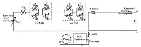
Figure 11.
Flow Battery Equivalent model.
The parameters shown in Figure 11 are dependent on the state of the battery (charge/discharge) and are highlighted in Table 3 and Table 4, while in Table 5 it is possible to see the Eocv values based on SOC.
Table 3.
Flow Battery parameters during the charge stage.
Table 4.
Flow Battery parameters during the discharge stage.
Table 5.
Eocv values.
For our purposes, we neglected the SOC Estimator function in the dynamic model implemented in Powerfactory shown in Figure 12.
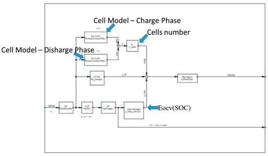
Figure 12.
Flow Battery dynamic model in Powerfactory.
The developed model automatically recognizes the battery state (charged/discharged) and sets the appropriate values of R0, Rct_a, Rct_c, Cdl_a, and Cdl_c. Furthermore, based on the calculated SOC value, the corresponding Eocv value was determined.
2.5. NG4 Configuration
In the NG4 configuration (see Figure 13), we disconnected the Flow Battery and we analyzed an unconventional storage system like the Fuel Cell technology. Table A5 in Appendix A shows the defined voltages thresholds for the NG4 configuration. Regarding the Fuel Cell dynamic model implemented in the Powerfactory, we started from the equivalent models shown in Figure 14 and Figure 15.
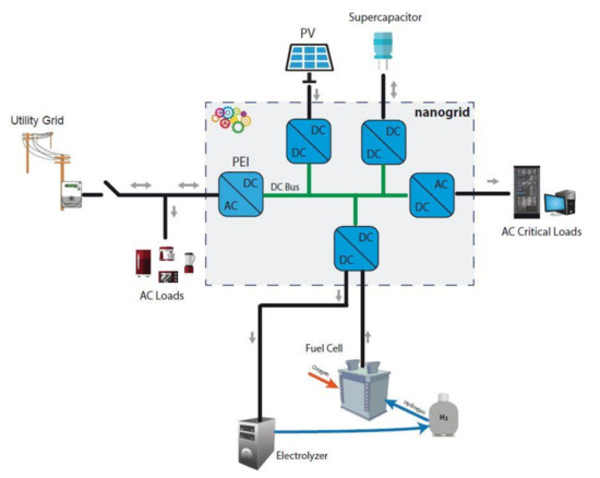
Figure 13.
NG4 Configuration.
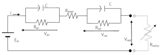
Figure 14.
PEM(Proton Exchange Membrane) Equivalent Model—Stack.
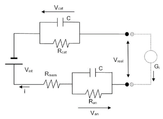
Figure 15.
PEM (Proton Exchange Membrane) Equivalent Model—Electrolyzer.
Starting from the aforementioned equivalent models, the related dynamic model (see Figure 16) was implemented with the aim to implement a single model capable of simulating both discharging and charging phases of the PEM (Proton Exchange Membrane) type storage system.
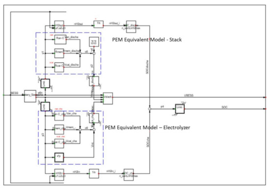
Figure 16.
PEM Dynamic Model.
2.6. NG5 & NG6 Configuration
The two last analyzed configurations are very similar to each other; the only difference between the two configurations is the unconventional storage system typology. Indeed, in the NG5 configuration (see Figure 17), the Fuel Cell storage technology was considered, while in the NG6 configuration (see Figure 18) we analyzed a new unconventional storage system Thermal Storage type.
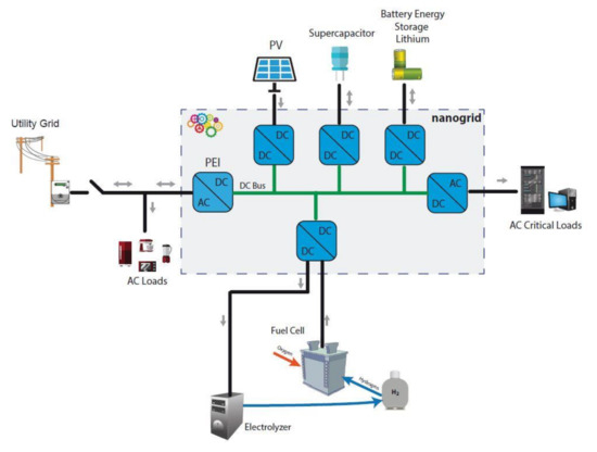
Figure 17.
NG5 Configuration.
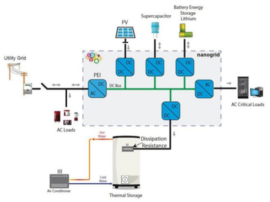
Figure 18.
NG6 Configuration.
The thermal storage has been considered as a variable load that can be activated by the DBS control if the DCNG bus voltage value rises above a defined voltage threshold. For this study’s purposes, the Decentralized resource control was updated with a new function named “Load Shedding” for the thermal storage activation (see Figure 19).
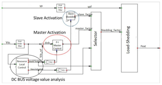
Figure 19.
Decentralized resource control with a Load-Shedding function for the Thermal Storage control.
3. Results
In order to assess the effectiveness of the proposed control logic, several DCNG configurations were considered. Each different storage technologies, whether conventional or unconventional, was analyzed to evaluate the control behavior of the DBS. Indeed, the presence in the DCNG of different storage technologies with a different time response, capacity, and voltage threshold for the master/slave roles activation can modify the DBS control response and its effectiveness.
For our purposes, each simulated configuration was set below the initial conditions, which meant that:
- There was no active power surplus/deficit in the DCNG;
- There was no power exchange with the external network;
- The initial DC Busbar voltage value for configuration was considered to be equal to 400 V.
To trigger the DBS control, we simulated a DC Busbar voltage variation afterwards using the variation of the Load in the DCNG. For the sake of simplicity, only one DC load was connected.
It is worth noting that all of the simulations highlighted the DBS’s ability to activate the energy storage system technology, thereby indicating that it is the most suitable option for playing the master role for each DCNG operating conditions in an optimized way.
Indeed, the first master activation requires a significant energy transfer in a very limited time interval to contain the DCNG voltage variation in a fast way. The DBS is able to activate the faster storage resource as the first master while the last activated master is the slower storage system, which is capable of providing energy in a large time interval.
The presence of the different storage solutions in the DCNG, thanks to the DBS management, makes the overall system capable of achieving optimal performances that are not obtainable using a single storage technology. The simulation results for each configuration are shown below.
3.1. NG1 Simulation
Figure 20 shows the active power variation for each resources option involving the grid after a sudden DC load active power increase. The Lithium battery has a Vref = 400 V (see Table A2 in Appendix A) and becomes the first master providing the active power to mitigate the DC BUS voltage variation and keeps the voltage value equal to Vref = 400 V (see Figure 21—DC Busbar voltage variation after a DC load increasing). When the Lithium Battery is fully discharged, it drops the master role and the DC BUS voltage decreases, becoming less than the PEI Vref and equal to 385 V. The PEI then takes on the master role and provides the required active power to keep the DCNG voltage value equal to Vref = 385 V.
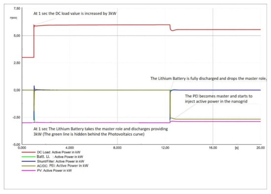
Figure 20.
Active Power variations per each asset in the DCNG after the DC load increases.
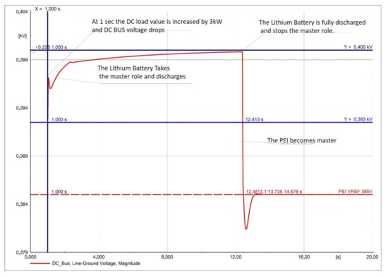
Figure 21.
DC Busbar voltage variations after the DC load increases.
The Figure 22 and Figure 23 show the active power and voltage behavior in the DCNG due to a sudden DC load decrease. As can be seen, the DBS control logic acts in the same manner as that described for the increasing DC load event but using different voltages for Vref and the threshold. Thanks to the control action, the DCNG voltage increase (see Figure 23) was mitigated by keeping its value close to PEI Verf value, which is equal to 415 V.
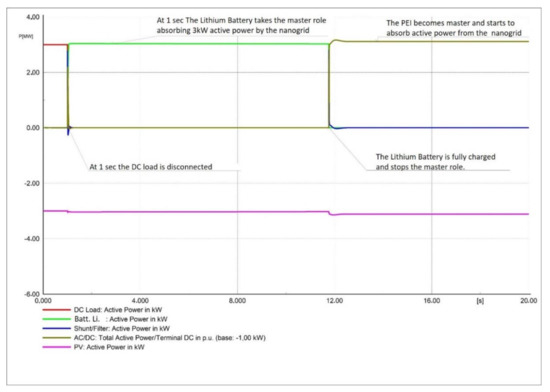
Figure 22.
Active Power variation for each asset in the DCNG after the DC load disconnection.
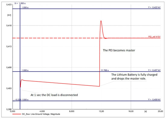
Figure 23.
DC Busbar voltage variation after a DC load following the DC load disconnection.
3.2. NG2 Simulation
Figure 24 shows the active power behavior in the DCNG due to the DC load increase and the DBS control action. The master activation sequence based on the voltages Vref is clearly defined in Table A3 in Appendix A.
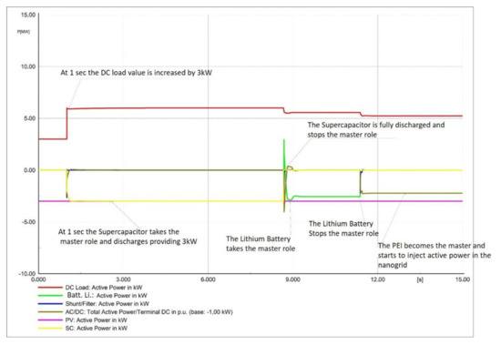
Figure 24.
Active Power variation for each asset in the DCNG after the DC load increases.
The Supercapacitor takes the master role after the instability event (the DC load increasing) and discharges, which provides the required active power to mitigate the DC BUS voltage decreasing. As a result, the voltage value remains close to Supercapacitor Vref = 400 V (see Figure 25).
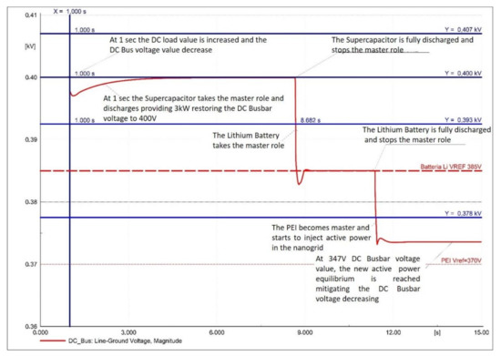
Figure 25.
DC Busbar voltage variation after the DC load increasing.
When the Supercapacitor is fully discharged, it drops the master role, leading to the voltage decreasing. The Lithium Battery takes the master role as soon as the voltage becomes less than 385 V.
The master provides the active power which mitigates the voltage value from decreasing until it is fully discharged and drops the master role. The DBS control action continues until the last master activation (PEI), stabilizing the voltage value close to PEI Vref value until it reaches the new active power equilibrium and mitigates the DC BUS voltage from decreasing.
Figure 26 and Figure 27 show the voltage and active power trend due to the DC loading sudden disconnection. As can be seen, thanks to the DBS control action, the voltage increasing can be effectively mitigated, thereby guaranteeing grid stability.
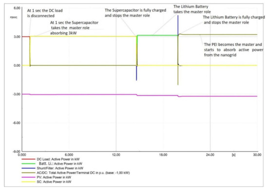
Figure 26.
Active Power variation per each asset in the DCNG after the DC load disconnection.
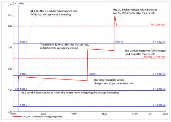
Figure 27.
DC Busbar voltage variation after the DC load disconnection.
3.3. NG3 Simulation
In the NG3 configuration, we analyzed the DBS control effectiveness, adding a Flow Battery in the DCNG. Indeed, with the storage systems increasing in the DCNG, the DBS control needed to be faster to avoid master role eventually overlapping among the storage systems in the grid.
It is worth noticing that both in the case of the DC load increasing and load deactivation, the masters are activated without overlapping and mitigating the voltage variation.
As shown in Figure 28, at 1 sec the DC load is increased and the Supercapacitor takes the master role, thereby providing the active power to keep the voltage value close to 400 V (see Figure 29). When the Supercapacitor is fully discharged, it drops the master role and simultaneously the Flow Battery adopts the master role, thereby providing active power. With the Flow Battery discharged, the voltage value decreases very quickly until the Lithium Battery becomes the master and the new active power equilibrium is obtained, keeping the voltage value close to 370 V.
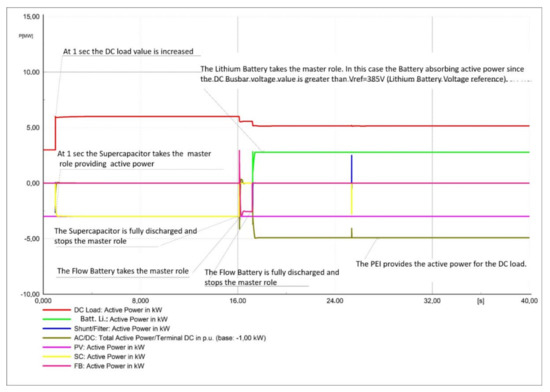
Figure 28.
Active Power variation per each asset in the DCNG after a DC load increases.
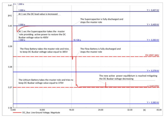
Figure 29.
DC Busbar voltage variation after a DC load increasing.
A sudden DC load disconnection is also shown in Figure 30 and Figure 31, which maintained the DBS Control effectiveness.
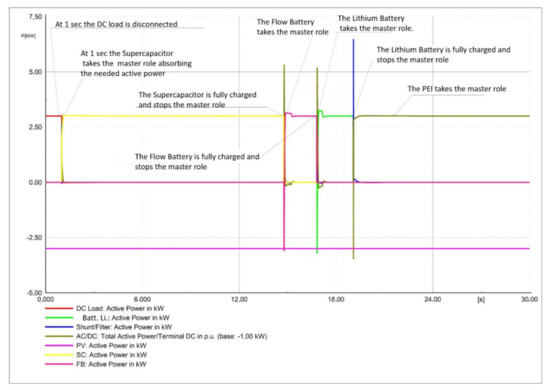
Figure 30.
Active Power variation per each asset in the DCNG after the DC load disconnection.
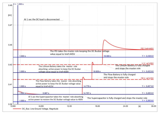
Figure 31.
DC Busbar voltage variation after the DC load disconnection.
3.4. NG4 Simulation
In the NG4 configuration, we assessed the DCNG behavior due to the presence of an unconventional storage system. In particular, we considered the Fuel Cell storage system. As can be seen in Figure 32 and Figure 33, the DBS control effectiveness remains when using unconventional storage in the grid too. No master role activation overlapping was detected and the DC BUS voltage variation mitigation due to instability event in the grid was obtained.
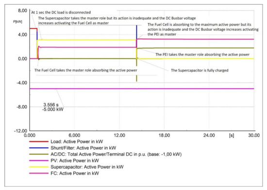
Figure 32.
Active Power variation per each asset in the DCNG after the DC load disconnection.
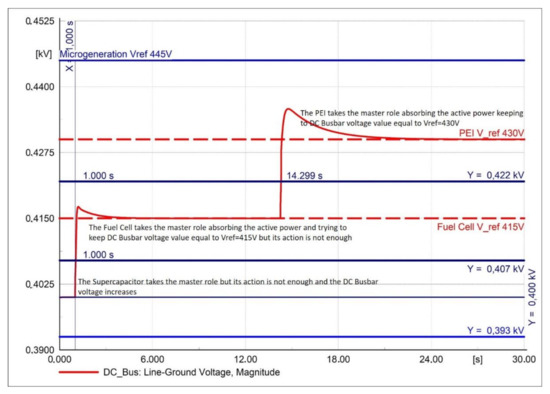
Figure 33.
DC Busbar voltage variation after the DC load disconnection.
3.5. NG5 Simulation
The NG5 configuration is very similar to NG4 configuration. The difference between the two configurations is the presence in the NG5 configuration of a Lithium Battery.
We can observe in the case of sudden DC load increasing that the voltage variation is very fast, leading to a non-activation of the Supercapacitor in the master role, although its Vref is equal to 400 V. Indeed, the first activated master is the Fuel Cell storage system while the Supercapacitor keeps the slave role (see Figure 34 and Figure 35). Moreover, the Lithium Battery activation is not needed since the master’s (Fuel Cell storage system) and slave’s (Supercapacitor) combined action is enough to contain the decreasing trend of the voltage.
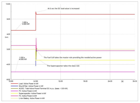
Figure 34.
Active Power variation per each asset in the DCNG after a DC load increases.
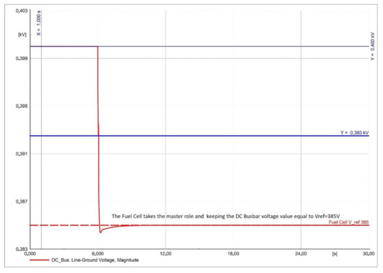
Figure 35.
DC Busbar voltage variation after a DC load increasing.
In the event of DC load disconnection, the voltage variation is not very fast and the Supercapacitor can be activated as the first master. However, in this case the Lithium Battery is also needed action to stop the voltage from increasing (see Figure 36 and Figure 37).
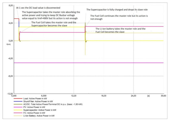
Figure 36.
Active Power variation for each asset in the DCNG after the DC load disconnection.
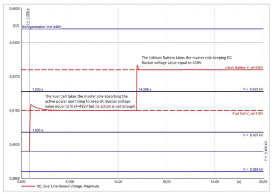
Figure 37.
DC Busbar voltage variation after the DC load disconnection.
3.6. NG6 Simulation
In this case study, we assessed the DCNG behavior while considering the presence of a Thermal storage system in the grid and while simulating a sudden DC load disconnection.
It is possible to observe that the voltage variation, due to the load disconnection, is very fast. Indeed, the Supercapacitor is activated as the first master but only keeps this role for a short time. The Lithium Battery then takes the master role and the Supercapacitor becomes a slave. However, their combined actions are not sufficient to stop the voltage from increasing. Thus, the Thermal storage system takes the master role and the Lithium Battery become a slave. Meanwhile the Supercapacitor is fully charged and drops its slave role. Their actions remain inadequate, and the DC voltage value continues to increase until the PEI becomes activated as a master (see Figure 38).
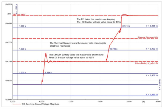
Figure 38.
DC Busbar voltage variations after the DC load disconnection.
4. Discussion
This paper has successfully modeled an energy hybrid system by integrating several technologies as different storage system type and micro resources in a grid-connected DCNG application. Although it is possible to connect several DCNGs directly through their DC bus to create an extended and different DC grid, in this paper, the focus was on a control strategy for different energy storage types in a single DC Nanogrid. Moreover, the different types of storage systems and sizes which have been used to create synergies in the several DCNG configurations and which have been considered and simulated have been identified through a careful cost-benefit and performance analysis addressed in [19]. Simulations have been undertaken by means of the DIgSILENT PowerFactory environment using embedded DIgSILENT Simulation Language (DSL). The implemented simulation framework allowed us to properly design the voltage thresholds which are used in the implementation of an integration strategy based on the well-known DBS control technique. Furthermore, this technique has been shown to be effective for managing several different technologies to exploit the technological peculiarities of their capability responses, e.g., energy or power capacities. In fact, as shown in Figure 24 and Figure 26 in the simulation results of NG2 configuration, the master activation sequence (Supercapacitor, Lithium, and PEI) driven by the DC BUS voltage provided the required energy capability. Meanwhile, a combined action of the Supercapacitor and Fuel Cell storage systems provided the required power capability, as depicted in Figure 34 and Figure 35 in the simulation results of NG5.
Finally, it is worth noting that despite the drawback of the variability of the DC BUS voltage value, it was maintained within operative constraints that allow for a safe load power supply.
5. Conclusions
Achieving growing autonomy, sustainability, and efficiency with respect to energy needs is a strategic goal that is now understood to be important. One possible tool which is capable of contributing to these results is represented by hybrid systems and therefore by the nanoGrids.
In the paper, the authors proposed a DC Bus Signaling (DBS) control strategy as a distributed and decentralized control approach to coordinate and manage several storage system technologies integrated in a DCNG.
The numerical results obtained show the effectiveness of using the DBS. In addition, it has been demonstrated that the value of the DC bus voltage thresholds for each analyzed DCNG configuration provides information that is sufficient to activate the resources that are actually available without any service interruptions.
Following this modeling analysis, a laboratory scale prototype of each analyzed DCNG configuration is now being evaluated in terms of strategy control effectiveness and robustness under a wide range of system operations while in the next step, a real-life application will then be implemented.
The next future works are focused on implementing a model that shows the effectiveness of using the DBS not only to locally control the energy needs of a single DCNG but also to satisfy the power profile request from an aggregator providing a service—for example, a balancing service when several DCNGs operate in an energy community framework.
Author Contributions
Conceptualization: R.C., A.P., and M.V. (Maurizio Vizza); Methodology: R.C., A.P., and M.V. (Maurizio Vizza), G.B., G.B.; Model implementation: R.C.; Data curation: R.C., A.P. and M.V. (Maurizio Vizza); Writing, review, and editing: R.C., G.G., and M.V. (Maria Valenti), M.V. (Maurizio Vizza), A.P., D.M., N.S., and G.B. All authors have read and agreed to the published version of the manuscript.
Funding
This research was funded by: the National Project “ComESto-Community Energy Storage” PON ricerca e innovazione 2014–2020 MIUR-ARS01_01259; and the National Operational Programme for Research and Innovation 2014–2020 “Fondo Sociale Europea, Azione 1.2, Attraction and International Mobility n° AIM1857122-2.
Institutional Review Board Statement
Not applicable.
Informed Consent Statement
Not applicable.
Data Availability Statement
Not applicable.
Conflicts of Interest
The authors declare no conflict of interest.
Appendix A
Table A1.
DCNG Configurations.
Table A1.
DCNG Configurations.
| CONVENTIONAL STORAGE | UNCONVENTIONAL STORAGE | ||||||||||
|---|---|---|---|---|---|---|---|---|---|---|---|
| Nanogrid Configuration |  |  |  |  |  |  |  |  |  |  |  |
| NG#1 |  | | | | |||||||
| NG#2 | | | | | | ||||||
| NG#3 | | | | | | | |||||
| NG#4 | | | | | | | |||||
| NG#5 | | | | | | | |||||
| NG#6 | | | | | | | |||||
Table A2.
NG1 Configuration.
Table A2.
NG1 Configuration.
 | PEI | Lithium Battery | PEI | PV |
|---|---|---|---|---|
 | 385 VDC | 400 VDC | 415 VDC | 430 VDC |
 | Absorb | Inject | Inject Pmax | |
| MPP | MPP | MPP | VCONST |
| Inject Pmax | Absorb Inject | Absorb Pmax | Absorb Pmax |

Table A3.
NG2 Configuration.
Table A3.
NG2 Configuration.
| PEI | Lithium Battery | Supercap | LithiumBattery | PEI | PV |
|---|---|---|---|---|---|---|
| 370 VDC | 385 VDC | 400 VDC | 415 VDC | 430 VDC | 445 VDC |
| Absorb | Inject | Inject Pmax | |||
| MPP | MPP | MPP | MPP | MPP | VCONST |
| Inject Pmax | Inject | Absorb | Absorb Pmax | Absorb Pmax | |
| Absorb Inject |

Table A4.
NG3 Configuration.
Table A4.
NG3 Configuration.
| PEI | Lithium Battery | Flow Battery | Supercap | Flow Battery | Lithium Battery | PEI | PV |
|---|---|---|---|---|---|---|---|---|
| 355 VDC | 370 VDC | 385 VDC | 400 VDC | 415 VDC | 430 VDC | 445 VDC | 460 VDC |
| Absorb | Inject | Inject Pmax | |||||
| MPP | MPP | MPP | MPP | MPP | MPP | MPP | VCONST |
| Inject Pmax | Inject | Absorb | Absorb Pmax | Absorb Pmax | |||
| Inject Pmax | Inject Pmax | Inject | Absorb | Absorb Pmax | Absorb Pmax | Absorb Pmax | |
| Absorb Inject |

Table A5.
NG4 Configuration.
Table A5.
NG4 Configuration.
| PEI | Fuel Cell | Supercap | Fuel Cell | PEI | PV |
|---|---|---|---|---|---|---|
| 355 VDC | 370 VDC | 400 VDC | 415 VDC | 430 VDC | 445 VDC |
| Absorb | Inject | Inject Pmax | |||
| MPP | MPP | MPP | MPP | MPP | VCONST |
| Inject Pmax | Inject | Absorb | Absorb Pmax | Absorb Pmax | |
| Absorb Inject |

Table A6.
NG5 Configuration.
Table A6.
NG5 Configuration.
| PEI | Lithium Battery | Fuel Cell | Supercap | Fuel Cell | Lithium Battery | PEI | PV |
|---|---|---|---|---|---|---|---|---|
| 355 VDC | 370 VDC | 385 VDC | 400 VDC | 415 VDC | 430 VDC | 445 VDC | 460 VDC |
| Absorb | Inject | Inject Pmax | |||||
| MPP | MPP | MPP | MPP | MPP | MPP | MPP | VCONST |
| Inject Pmax | Inject | Absorb | Absorb Pmax | Absorb Pmax | |||
| Inject Pmax | Inject Pmax | Inject | Absorb | Absorb Pmax | Absorb Pmax | Absorb Pmax | |
| Absorb Inject |

Table A7.
NG6 Configuration.
Table A7.
NG6 Configuration.
| PEI | Lithium Battery | Supercap | LithiumBattery | Thermal Storage | PEI | PV |
|---|---|---|---|---|---|---|---|
| 370 VDC | 385 VDC | 400 VDC | 415 VDC | 430 VDC | 445 VDC | 460 VDC |
| Absorb | Inject Pmax | Inject | ||||
| MPP | MPP | MPP | MPP | MPP | MPP | VCONST |
| Absorb | Absorb Pmax | Absorb Pmax | ||||
| Inject Pmax | Inject | Absorb | Absorb Pmax | Absorb Pmax | Absorb Pmax | |
| Absorb Inject |

Appendix B
| C | Capacitor value that represents the Double Layer charging during the load variation phase; |
| Ideal stack voltage; | |
| Stack current generator; | |
| i | Stack Current; |
| Anode Resistance; | |
| Cathode Resistance; | |
| Membrane Resistance; | |
| Load; | |
| Anode Voltage Drop(Stack)/Anode Overvoltage(Electrolyzer); | |
| Cathode Voltage Drop(Stack)/Cathode Overvoltage(Electrolyzer); | |
| Stack Voltage; | |
| Ideal stack voltage. |
References
- Hart, E.K.; Stoutenburg, E.D.; Jacobson, M.Z. The potential of intermittent renewables to meet electric power demand: Current methods and emerging analytical techniques. Proc. IEEE 2011, 100, 322–334. [Google Scholar] [CrossRef]
- Herisanu, N.; Marinca, V.; Madescu, G.; Dragan, F. Dynamic response of a permanent magnet synchronous generator to a wind gust. Energies 2019, 12, 915. [Google Scholar] [CrossRef]
- Khatod, D.K.; Pant, V.; Sharma, J. Analytical approach for well-being assessment of small autonomous power systems with solar and wind energy sources. IEEE Trans. Energy Convers. 2009, 25, 535–545. [Google Scholar] [CrossRef]
- Hajiaghasi, S.; Salemnia, A.; Hamzeh, M. Hybrid energy storage system for microgrids applications: A review. J. Energy Storage 2019, 21, 543–570. [Google Scholar] [CrossRef]
- Bocklisch, T. Hybrid energy storage systems for renewable energy applications. Energy Procedia 2015, 73, 103–111. [Google Scholar] [CrossRef]
- Musale, R.; Student, P.G.; Bhusawal, S. A DBS Control Method for Coordinating Multiple Energy Storage Devices in DC Micro grid. Resincap J. Sci. Eng. 2020, 4, 6. [Google Scholar]
- Ciavarella, R.; Graditi, G.; Valenti, M.; Pinnarelli, A.; Barone, G.; Vizza, M. An Advanced DBS Strategy for a DC nanogrid integrating several energy storage technologies. In Proceedings of the International Symposium on Power Electronics, Electrical Drives, Automation and Motion (SPEEDAM), Sorrento, Italy, 24–26 June 2020; pp. 351–356. [Google Scholar]
- Zaid, Z.H.; Lopes, L.A. Control Scheme for a Hybrid Energy Storage System Employed in a Grid-Tied DC Nano-grid. In Proceedings of the IEEE 29th International Symposium on Industrial Electronics (ISIE), Delft, The Netherlands, 17–19 June 2020. [Google Scholar]
- Menniti, D.; Pinnarelli, A.; Sorrentino, N.; Belli, G. A Local Market Model Involving Prosumers Taking Into Account Distribution Network Congestions in Smart Cities. Int. Rev. Electr. Eng. (IREE) 2014, 9, 976–985. [Google Scholar] [CrossRef]
- Asif, A.A.; Singh, R.; Majumder, A.J.A. The Paradigm Shifting Role of Solar Powered DC Nano-Grids in New Electrification and Replacement for Traditional Grid Distribution. In Proceedings of the 2020 Clemson University Power Systems Conference (PSC), Clemson, SC, USA, 10–13 March 2020; pp. 1–6. [Google Scholar]
- Chen, D.; Xu, L.; Yao, L. DC Voltage Variation Based Autonomous Control of DC Microgrids. IEEE Trans. Power Deliv. 2013, 28, 637–648. [Google Scholar] [CrossRef]
- Garg, A.; Joshi, B.M.; Oruganti, R. Modeling a DC Microgrid with real-time Power Management using DC Bus Signalling. In Proceedings of the IEEE Energy Conversion Congress & Expo, Portland, OR, USA, 23–27 September 2018; pp. 46–53. [Google Scholar]
- Xu, L.; Chen, D. Control and Operation of a DC Microgrid with Variable Generation and Energy Storage. IEEE Trans. Power Deliv. 2011, 26, 2513–2522. [Google Scholar] [CrossRef]
- Zubieta, L.E. Power Management and Optimization Concept for DC Microgrids, in DC Microgrids (ICDCM). In Proceedings of the IEEE First International Conference, Atlanta, GA, USA, 7–10 June 2015; pp. 81–85. [Google Scholar]
- Quintana-Barcia, P.; Dragicevic, T.; Garcia, J.; Ribas, J.; Guerrero, J.M. A distributed control strategy for islanded single-phase microgrids with hybrid energy storage systems based on power line signaling. Energies 2019, 12, 85. [Google Scholar] [CrossRef]
- Hwang, P.I.; Jang, G.; Pyo, G.C.; Han, B.M.; Moon, S.I.; Ahn, S.J. Dc microgrid operational method for enhanced service reliability using DC bus signaling. J. Electr. Eng. Technol. (JEET) 2015, 10, 452–464. [Google Scholar] [CrossRef]
- Garg, A.; Tummuru, N.R.; Oruganti, R. Implementation of Energy Management Scenarios in a DC Microgrid using DC Bus Signaling. In Proceedings of the 2020 IEEE International Conference on Power Electronics, Smart Grid and Renewable Energy (PESGRE2020), Cochin, India, 2–4 January 2020. [Google Scholar]
- Papadimitriou, N.; Zountouridou, E.I.; Hatziargyriou, N.D. Review of hierarchical control in DC microgrids. Electr. Power Syst. Res. 2015, 122, 159–167. [Google Scholar] [CrossRef]
- Pinnarelli, A.; Menniti, D.; Sorrentino, N.; Bayod, A.A. Distributed Energy Resources in Local Integrated Energy Systems, Optimal Operation and Planning; Chapter 8; Graditi, G., di Somma, M., Eds.; Elsevier: Amsterdam, The Netherlands, 2021; ISBN 9780128238998. [Google Scholar]
- Jian, Z.; He, Z.; Jia, J.; Xie, Y. A Review of Control Strategies for DC Micro-grid, Intelligent Control and Information Processing (ICICIP). In Proceedings of the 4th International Conference, Beijing, China, 9–11 June 2013; pp. 666–671. [Google Scholar]
- Kumar, J.; Agarwal, A.; Agarwal, V. A review on overall control of DC microgrids. J. Energy Storage 2019, 21, 113–138. [Google Scholar] [CrossRef]
- Bryan, J.; Duke, R.; Round, S. Decentralized generator scheduling in a nanogrid using DC bus signaling. In Proceedings of the IEEE Power Engineering Society General Meeting, Denver, CO, USA, 6–10 June 2004; pp. 977–982. [Google Scholar]
- Schonbergerschonberger, J.; Duke, R.; Round, S.D. DC-Bus Signaling: A Distributed Control Strategy for a Hybrid Renewable Nanogrid. IEEE Trans. Ind. Electron. 2006, 53, 453–1460. [Google Scholar] [CrossRef]
- Zhang, L.; Wu, T.; Xing, Y.; Sun, K.; Guerrero, J.M. Power control of DC microgrid using DC bus signaling. In Proceedings of the IEEE Twenty-Sixth Annual Applied Power Electronics Conference and Exposition (APEC), Fort Worth, TX, USA, 6–11 March 2011; pp. 1926–1932. [Google Scholar]
- Sun, K.; Zhang, L.; Xing, Y.; Guerrero, J. A Distributed Control Strategy Based on DC Bus Signaling for Modular Photovoltaic Generation Systems with Battery Energy Storage. IEEE Trans. Power Electron. 2011, 26, 3032–3045. [Google Scholar] [CrossRef]
- Li, F.; Lin, Z.; Qian, Z.; Wu, J. Active dc bus signaling control method for coordinating multiple energy storage devices in dc microgrid. In Proceedings of the IEEE Second International Conference on DC Microgrids (ICDCM), Nuremburg, Germany, 27–29 June 2017; pp. 221–226. [Google Scholar]
- Jin, C.; Wang, P.; Xiao, J.; Tang, Y.; Choo, F.H. Implementation of Hierarchical Control in DC Microgrids. IEEE Trans. Ind. Electron. 2014, 61, 4032–4042. [Google Scholar] [CrossRef]
- Han, J.X.; Xiao, W. Advanced Control Scheme for DC Microgrid via Dual Active Bridge and Bus Signaling. In Proceedings of the 2019 IEEE 28th International Symposium on Industrial Electronics (ISIE), Vancouver, BC, Canada, 12–14 June 2019. [Google Scholar]
- Chen, M.; Rincon-Mora, G.A. Accurate electrical battery model capable of predicting runtime and I-V performance. IEEE Trans. Energy Convers. 2006, 21, 504–511. [Google Scholar] [CrossRef]
- Bhattacharjee, A.; Roy, A.; Banerjee, N.; Patra, S.; Saha, H. Precision dynamic equivalent circuit model of a Vanadium Redox Flow Battery and determination of circuit parameters for its optimal performance in renewable energy applications. J. Power Sources 2018, 396, 506–518. [Google Scholar] [CrossRef]
- Adinolfi, G.; Ciavarella, R.; Graditi, G.; Merola, A.; Valenti, M. Coordinated Control of Supercapacitor-Battery Tandem by Smart Converters in Microgrid Scenario. Lect. Notes Electr. Eng. 2020, 604, 669–678. [Google Scholar]


Publisher’s Note: MDPI stays neutral with regard to jurisdictional claims in published maps and institutional affiliations. |
© 2021 by the authors. Licensee MDPI, Basel, Switzerland. This article is an open access article distributed under the terms and conditions of the Creative Commons Attribution (CC BY) license (http://creativecommons.org/licenses/by/4.0/).