Abstract
In this study, an experimental outdoor investigation of the thermal efficiency and outlet air temperature was conducted on an unglazed, double-pass, solar air heater with a perforated absorber plate and packing wire mesh layers as a supplemental absorbent area. This was done to observe their effects on the thermal performance of the solar air heater. The double-pass collector was constructed with a bed height of 0.05 m, and a collection area of 1.5 m2. The height of the upper channel was fixed at 0.015 m to improve the thermal efficiency, and the outlet temperature at air flow rates between 0.003 and 0.018 kg/s. The collector was mounted with a slope of 42° facing south, to maximize the intensity of solar irradiance during winter. The effects of the air flow rate, ambient temperature, inlet temperature, outlet temperature, and solar intensity were experimentally investigated. The results showed that thermal efficiency could be improved by increasing the air flow rate, where the highest thermal efficiency achieved was 86% at 0.018 kg/s. However, the temperature difference was increased to a maximum value of 38.6 °C, when the air flow rate was decreased to 0.003 kg/s. Furthermore, the results demonstrated a significant improvement in the thermal efficiency and outlet temperature; and when compared with previous research, the experimental results and the predictions for the outlet temperature using the theoretical model agreed.
1. Introduction
Energy is vital to human life. The rapid increase in the global economy and technological development, as well as population growth, has increased the demand for energy. Most energy is produced from nonrenewable sources, such as fossil fuel, because of the low cost of production and large supply. The fossil fuel production generates various hazards to the environment, and to human health—such as acid rain, global warming, and photochemical smog [1].
Utilizing a solar energy system for heating space, such as using solar air collectors, is a clean technique to decrease CO2 emissions and resource consumption [2]. This type of heating system is low-cost and easy to maintain, but has the disadvantage of low thermal efficiency [3]. Solar air collectors have several advantages compared to application of other, liquid-type solar energy systems, such as no freezing or corrosion problems, less maintenance required, and ability to use a perforated plate system (which provides fresh air that improves the indoor air quality).
Solar air heaters can be classified into two basic modes: glazed collectors and unglazed transpired collectors. The unglazed transpired collector is relatively new solar technology that was developed in the 1980s for ventilation air heating. The absorber part of the unglazed transpired collector is perforated so that ambient air is continuously withdrawn through the perforations [4]. Much technological and financial effort has gone into research on improving the thermal efficiency of solar collectors, because of their use as a renewable energy resource, lack of implementation, and environmental friendliness [5]. Multiple factors affect the solar collector efficiency, such as meteorological parameters (ambient temperature, wind speed, and solar intensity); design parameters (collector materials, size, and type); flow parameters (flow pattern, air flow rate, mode of flow, collector cover, absorber shape); and material (e.g., black-colored wood, aluminum, thin steel plate) [6]. The most important parameters that affect thermal efficiency are the absorber plate, the collector cover, and the air flow pattern inside the collector [7].
Several investigators have undertaken experiments regarding heat transfer analysis of solar energy systems, such as the unglazed transpired solar heaters without cover glasses that have been studied by Bhushan and Singh [8]. One theoretical investigation analyzed the thermal efficiency of the unglazed transpired solar heaters [9], while another predicted theoretical efficiency as a function of wind speed, suction velocity, ambient temperature, and radiation [10]. It has been found that a hole’s pitch and diameter are affected by heat transfer between the perforated absorber plate and passing air through holes [11]. Another study found that the non-uniform air flow caused by using porous media has a greater heat transfer coefficient than that in uniform air flow without porous media; and that for the same collector, it was better to put porous media at the lower part of a double pass solar collector [12]. Empirical relations for heat transfer coefficients were estimated [13]. A numerical model was developed to analyze the efficiencies of unglazed transpired solar collectors. Decker et al. [14] improved the model from Bhushan and Singh [8], and developed a wider range and higher accuracy model to predict the efficiencies of collectors.
A double-pass counter-flow was conducted to improve the thermal performance of the transpired solar heater [15]. Several studies have shown that the double-pass solar collectors were more efficient than single-pass solar heaters [16]. Packed bed lower or upper absorber plates were used for improving thermal efficiency and outlet temperature [17]. The model for the solar collector with a double-pass or counter-flow indicates that increasing the air flow proportionally increases the percentage temperature rise of the channel [18]. Some researchers investigated the thermal performance of a double-pass, counter-flow solar collector with porous material in the second air passage [19]; they studied the behavior of the solar collector with and without porous media, and compared them according to various governing parameters, such as the air mass flow rate, inlet air temperature, spacing between the top cover and absorber plate, and the intensity of the solar radiation [20]. The solar heater achieved a higher thermal efficiency with porous media than without porous media. The thermal conductivity of the porous media was found to have a significant effect on the thermal performance of the solar heater [21]. The thermal efficiencies of double-pass air heaters with matrix absorber lower channels were 25% higher than collectors without a matrix absorber [22].
A double-pass solar heater, with wire mesh layers and quarter perforated cover plate, was presented by Nowzari et al. [23], and the maximum temperature value reached was 46 °C. Unglazed solar transpired collector systems offer potential low cost and high efficiency. While numerous authors reported favorable results [24] after improving the efficiency of the transpired collectors, some experimentally and numerically studied the unglazed transpired collector in cold claimant for heating space [25]. Moreover, some researchers used transpired solar collectors with perforating corrugated plates [26], or protruded absorber plates with roughened solar air heaters [14], and others were invented, such as the absorber plate with circular holes, slit-like perforations, multi v-shaped gap ribs, and roughened protrusions [27], enabling them to save a large amount of thermal energy.
As seen from previous studies, researchers are working to improve the performance of the thermal efficiency and outlet temperature of the solar thermal processes. Thus, the aim for this research was to invent new designs using a double-pass unglazed transpired collector with a perforated plate and wire mesh packed, as shown in Figure 1 and Figure 2. The important contribution of this research was using wire mesh layers (increasing the absorbing area) and a perforated absorber plate, and the double-pass counter-flow collector in the duct, to enhance thermal performance. The purposes of the used double-pass, counter-flow collector include: First, increasing the air path to gain more heat and minimize heat loss to the surroundings; and second, maximizing heat transfer to the airstream in the upper channel.
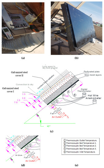
Figure 1.
(a,b) Photos of a solar energy system; (c,d) scheme of the studied double-pass unglazed solar energy system; (e) sensor number.
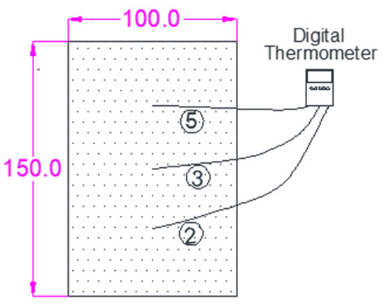
Figure 2.
The scheme shows the location of thermostable for measuring bed temperatures.
2. Experimental Setup
2.1. Construction and Design
The structure of the new transpired flat-plate collector was constructed and performed in Baghdad, Iraq 33.3152° N, 44.3661° E, double-pass-counter flow collector is shown in Figure 1. The double pass collector made of wood, with an area of 1.5 m2 (1.5 m long and 1 m width). All edges and bottom of the collector were thermally insulated, except the upper side of the collector. Two ordinary panes of the plate (steel galvanized), the thickness of 4 mm were fixed parallel and upper the collectors to allow the inlet air to pass through these two plates in a space of 1.5 cm (upper channel), the flow then reversed direction to inter the bottom of the collector, lower channel (lower channel: The distance from Galvanized steel cover II to the back bed), high of 7 cm. The main components of the collectors were the six aluminum wire mesh layers (square hole area 2.2 × 2.2 mm2) and galvanized steel perforated absorber plate, hole diameter 2 mm and pitch 4 mm. The collectors’ bed, perforated plate and wire mesh layers were painted black before installation to increase the absorbing heat from the solar rays and improving the efficiency. A blower of 0.75 kW was connected with collectors by flexible (8 cm diameter) pipe, vary air mass flow rate from 0.003 to 0.018 kg/s controlled by controller speed inverter model: SV008iC5-1, 0.01−400 Hz, 5 A was fixed with air blower electricity, for more detail see Table 1.

Table 1.
The characteristics of the equipment used during the tests.
2.2. Methodology
In this study, outdoor experiments setup was conducted and developed in Baghdad, Iraq. Solar air collector was thermal performance and tested for five cloudless days in April 2019, the slope of 42° facing south, thus, maximizing the solar intensity for winter days. The measurement equipment was a data-logger (EXTECH), an accuracy of ± (0.4% + 1 °C), model SDL200, using for obtained inlet, plenum and outlet temperatures and Pyranometer placed lower to the collector to sense the global solar irradiance (Pyranometer RK200-03, 0–2000 w/m2 Range, SN: R18021068) used for measuring solar intensity. The air velocity was measured and taken manually by HT-9829, 60–90 mA, hot wire anemometer, and solar intensity and temperatures were registered automatically every 30 min a day. A vacuum blower power of 0.75 kW, model 135C16A was used to discharge five air flows during five-day work, from 0.003 to 0.018 kg/s. A blower speed controlled by using the inverter drive speed control model: SV008iC5-1, 5 A, 0.01–400 Hz.
3. Instantaneous Efficiency of the Solar Collector
To evaluate the performance of the solar heater system, the first law of thermodynamic was applied, and the thermal efficiency was defined as the ratio of the useful energy to receive energy, and the useful energy was defined as the thermal energy, and receives energy as heat flux or solar radiation energy.
where useful energy gain and received energy in (W), ṁ is the air flow rate (kg/sec), Cp is the specific heat of the air (kJ/kg K), Ac is the collector area in (m2), (To) is the outlet air temperature (°C), and Ti is the inlet air temperature (°C) [19,20].
Equation (2) can be simplified to:
It is clear from Equation (3), that there is a linear relationship between ηth and (To−Ti)/I, the positive slope given with .
The performance of flat plate solar collector operating under steady conditions can be successfully described Equation (4). Thermal efficiency is solved heat removal coefficient (FR) as shown [19]:
where (τα) is the effective transmittance absorbance product, (UL) is the overall heat loss coefficient in W/ (m2 K), and (FR) is the collector heat removal factor which relays the actual useful energy gain to the useful gain that the collector surface was at the air inlet temperature. For this state Equation (4) gives a linear relationship between and (Ti−Ta)/I, but a negative slope of [−(FR UL)/I], and the origin order at FR (τα).
4. Experimental Results
4.1. Ambient Temperature, Relative Humidity and Solar Intensity
Daily values of ambient air temperature, relative humidity and solar radiation incident were registered from 08:00 to 16:00 within a period between 23–27 April 2019 at Baghdad, Iraq. Figure 3, shows the total average for those parameters within the five days of the experimental work. The average ambient air temperature was increased slightly from 11 °C, with a solar intensity value of 340 W/m2, in the morning to 18 °C, with a solar intensity value of 110 W/m2, at the end of the day. The average maximum solar intensity was 820 W/m2 at noon. The average relative humidity dropped, as opposed to the average ambient air temperature, during the day from 08:00 a.m. to 16:00 p.m., where the maximum value, 82%, was seen in the morning then falls to 52% in the evening.
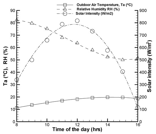
Figure 3.
The average outdoor temperatures were associated with solar intensity and humidity ratio.
4.2. Inlet Temperature, Bed Temperature and Outlet Temperature
Figure 4 illustrates the ambient temperature (Ta), inlet temperature (Ti), bed temperature (Tb) and outlet temperature (To), with the time of the day from morning 08:00 to evening 16:00, for five different air flow rate from 0.003 kg/s to 0.018 kg/s. Temperature curves (Ta), (Ti), (Tb) and (To) had a similar manner with the solar intensity, increased to the maximum value at noon then decreased at the end of the day. The inlet air temperature (Ti) was higher than the ambient temperature (Ta). The ambient temperature was measured at a shadow place nethermost the bed, while (Ti) measured at entrance of the bed. The outlet temperatures (To) were greater than bed temperatures (Tb), (bed temperature means the temperature of the passing air inside the bed at the middle), for all days of experiments. This behavior was due to the double-pass of unglazed collectors or the counter-flow, which means that the passing air was preheated in the upper channel before the air flow reversed direction to enter the lower channel. Furthermore, (Tb) and (To) increase as the air flow rate was decreased from 0.003 kg/s to 0.018 kg/s, mainly due to the increase in the time of the moving air through the collector (from inlet section to the end of the collector). In other words, the air was able to carry more heat from the perforated plate and the wire mesh. Table 2 present the average value of inlet temperature, bed temperature, outlet temperature, and solar intensity with different air flow rate.
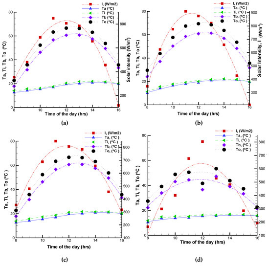
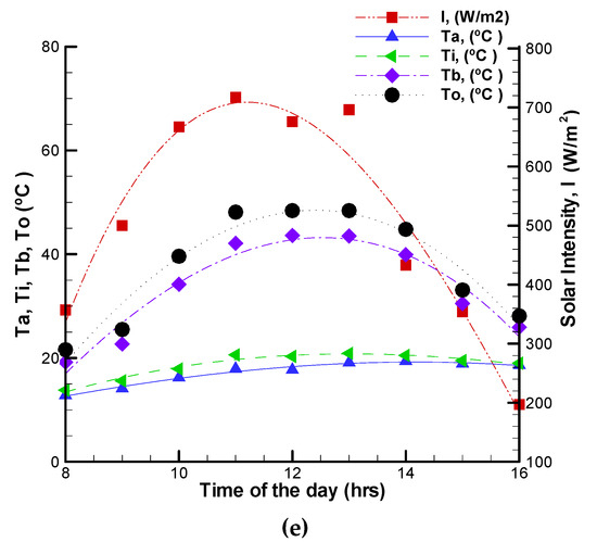
Figure 4.
Inlet temperature, bed temperature, outlet temperature and solar intensity for: (a) Day 1: m = 0.003 kg/s; (b) Day 2: m = 0.005 kg/s; (c) Day 3: m = 0.013 kg/s; (d) Day 4: m = 0.016 kg/s; (e) Day 5: m = 0.018 kg/s.
Table 2.
The average value of the solar intensity (I), ambient temperatures (Ta), bed temperatures (Tb) and outlet temperatures (To) with different air flow rate.
4.3. Temperature Differences between the Outlet and Inlet Temperatures ∆T
Figure 5 shows the temperature differences (ΔT = To – Ta) with time, for different air flow rate (from 0.003 kg/s to 0.018 kg/s) increased from the morning at 08:00 to reach a maximum temperature at noon, then afternoon the (ΔT) slowly decreased to the end of the day at 16:00. The maximum temperature differences (ΔT) is obtained 52.5°C with a solar intensity of 925 W/m2, at an air flow rate of 0.003 kg/s, where the (To) of the flowing air through the collector increased with decreasing airflow rate
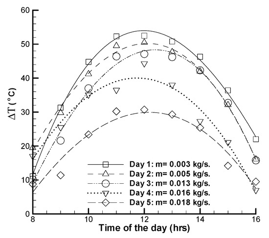
Figure 5.
Temperature differences between the outlet and inlet temperature with the time of the day.
The results of temperature differences (as shown in Table 1) was compared with the previously unglazed transpired collectors published data, there was an enhancement in the heat transfer performance. The study of Kutscher [11] was obtained a maximum (ΔT) of 32 °C for at I = 700 W/m2 for an air flow rate of 0.02 kg/s and perforated absorber area of 3 m × 3 m. The research [28], for numerical values, obtained, by neglecting the natural convection loss have obtained a maximum (ΔT) of 35 °C for at I = 800 W/m2, air flow rate of 0.015 kg/s and perforated absorber area of 2 m × 3 m. Rad and Ameri [29] obtained the highest (ΔT) of 15 °C with a bed area of 2.79 m × 1.5 m at an air flow rate of 0.02 kg/s and I = 800 W/m2. Theoretical and experimental investigated [30], for unglazed perforated solar air collector, which is coupled to a capillary heating system, the (∆T) of 14.7 °C for ambient temperature (Ta) of 10 °C at = 0.005 kg/s, and bed area of 1.2 m × 2.2 m.
4.4. Thermal Efficiency (η)
From Equation (4), if the efficiency is plotted against the temperature parameter (Ti−Ta)/I, a straight line was made where the slope is indicative of (UL), and the y-intercept is indicative of (τα). In fact, (UL) is not a constant, but a function of the ambient temperature and the outlet temperature of the collector. Figure 6 presents the instantaneous thermal efficiency (ηi) of the collector versus (Ti– Ta)/I, for air flow rate of 0.018 kg/s. The maximum efficiency gained 86%, for air flow rate 0.018 kg/m2 (Day 5), with the negative linear fit behavior slope B = −1.1782 and a correlation coefficient R2 = 0.5566. The temperature parameter (Ti−Ta)/I is increased as the thermal efficiency decreased, increasing of (Ti−Ta)/I caused an increase in the heat loss from the upper cover to the surrounding, thus, thermal efficiency is reduced. There was a fluctuation of thermal efficiency value during Day 4, due to the part cloudy day, that effect on the solar intensity and thermal efficiency of the collector. Thus, the slope of the curve Day 4 seems straight line or low slope (not like other days), the constant A and B, are higher than constant A and B for Days 1–3, and 5.
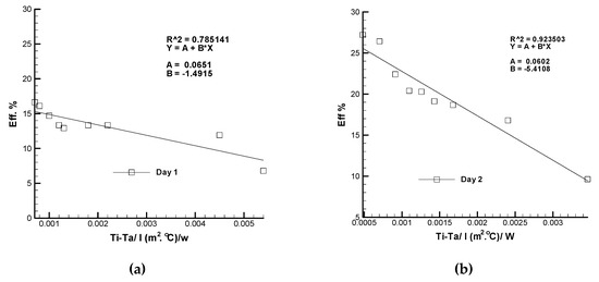
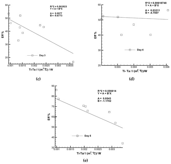
Figure 6.
Instantaneous thermal efficiency (ηi) of the collector versus (Ti – Ta)/I, (a) air flow rate 0.003 kg/s; (b) air flow rate 0.005 kg/s; (c) air flow rate 0.013 kg/s; (d) air flow rate 0.016 Is; (e) air flow rate 0.018 kg/s.
The obtained empirical expression:
Replacing the slope by B and the origin by A, we obtain
Adding Equations (6) and (3), we find the expression for (To) as a function of inlet air temperature (Ti) and the ambient temperature (Ta):
where the variable λ is defined as:
Replacing in Equation (7) the values of B, A and λ of our prototype, the model for the tested counter-flow, a double-pass solar collector is:
To = 0.3443 Ti + 0.6557 Ta + 0.0651 I (for Day 1 at m = 0.003 kg/s)
To = −0.5392Ti + 1.5932 Ta + 0.0602 I (for Day 2 at m = 0.005 kg/s)
To = −0.1414Ti + 1.1414 Ta + 0.0577 I (for Day 3 at m = 0.013 kg/s)
To = 0.5477 Ti + 0.4523 Ta + 0.5321 I (for Day 4 at m = 0.016 kg/s)
To = 0.9954 Ti + 0.0046 Ta + 0.0541 I (for Day 5 at m = 0.018 kg/s)
If the ambient temperature was the same inlet temperature (Ta = Ti), then Equation (9) given as:
To = Ta + 0.0651 I (for Day 1 at m = 0.003 kg/s)
To = Ta + 0.0602 I (for Day 2 at m = 0.005 kg/s)
To = Ta + 0.0577 I (for Day 3 at m = 0.013 kg/s)
To = Ta + 0.5321 I (for Day 4 at m = 0.016 kg/s)
To = Ta + 0.0541 I (for Day 5 at m = 0.018 kg/s)
Figure 7 shows experimental outlet temperatures (To, Measured) and simulated temperatures (To, Simulated) versus hours of the day at different airflow rate, that given by Equation (10). Clear from Figure 7, there was a validation of the work conditions, for the double-pass, unglazed solar energy system. The different value between experimented and predicted data were between (0 to 5) °C, for all days of work. The experimental work and simulated work agreed. There was a mismatch between experimented and predicted curves, due to the outdoor work condition, that affected on the outlet temperature. They fluctuated for inlet temperature, solar intensity, wind speed and humidity are caused some unstable outlet temperature with time of the day.
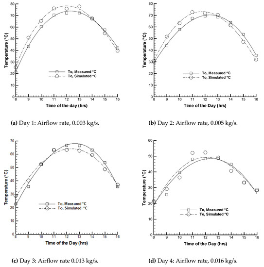
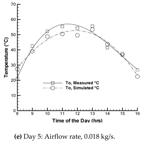
Figure 7.
Experimented and predicted data of outlet air temperature for (a) Day 1; (b) Day 2; (c) Day 3; (d) Day 4 and (e) Day 5.
4.5. Effects of Airflow Rate
As estimated from Equation (3), the thermal efficiency of the collector can be improved by raising the air flow rate. The experimental results in Figure 8 show the thermal efficiencies for each day with different air flow rates raised from 0.003 kg/s to 0.018 kg/s. The weather condition of air inlet temperature (Ti) 21°C and the solar intensity 456 W/m2. Evidently, there was a fluctuation of thermal efficiency value during Day 4, that was due to the partly cloudy, that effect on the solar intensity and efficiency for Day 4.
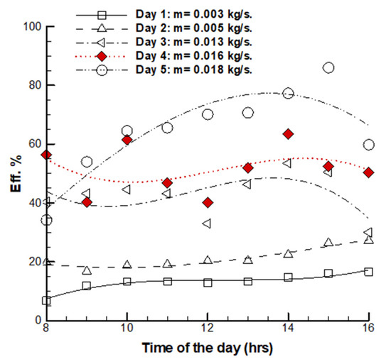
Figure 8.
Variation of thermal efficiency at different air flow rates with the time of the day.
The high efficiency is caused by: First, the passing air through the upper channel is preheated the inlet air temperature before entering the bed. Second, the larger heat transferred between the passing air and absorber area (perforated plate and wire mesh layers). Third, the perforated plate acts as air jet impingement, the passing air through the hole enhancement the convective heat transfer.
The thermal efficiency in the present work was compared with the previously reported data. The proposed present new prototype of the unglazed solar collector showed significant improvement in the thermal efficiency, for air flow rate of 0.018 kg/s, as shown in Table 3.
Table 3.
Shows significant improvement in the thermal efficiency with for air flow rate (0.018 kg/s).
As demonstrated in Figure 9, the efficiency increased continuously with the air flow rate, i.e., the heat transfer rate is directly proportional to the air flow rate. The increase in the air flow rate increased the convection heat transfer coefficient, thus, enhancing the heat transfer from the collector to the working fluid. At the maximum air flow rate, 0.018 kg/s, the outlet temperature (To) was at the minimum value. By lowering the air flow rate the outlet temperature (To) increased, due to the increase in the time of moving air, the air took more time to move from the inlet section to the end of the collector. Thus, the air carried more heat from the perforated plate and the wire mesh layers. Therefore, the application of the solar energy system in cold weathers should be at a low air flow rate to satisfy the thermal comfort of the buildings. At the minimum air flow rate, 0.003 kg/s, the maximum average temperature difference (∆Tave.), 38.6 °C, was achieved with average inlet temperature (Ta ave.) of 17.7 °C and average solar intensity (Iave.) of 661 W/m2 (Day 1 of the work).
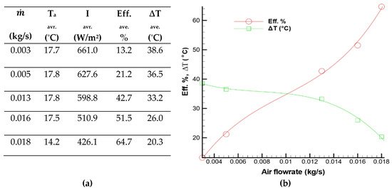
Figure 9.
(a) Table of the average solar intensity and inlet air temperature, thermal efficiencies and temperature differences for five-day work; (b) variation of the average temperature differences and the average thermal efficiencies with the air flow rate for five-day work.
A solar energy system that is designed for high efficiency would have a high air flow rate and low outlet temperature. During low outside temperature (climate degree), the building manager would feel that the air is “cold” and think the collector is not working well. Thus, to ensure reaching the required level of heating, a conventional heater would need to be attached to the air flowing to the building. However, by setting the solar energy system for high-temperature, lower air flow rates should be used. This can satisfy the heating requirement of the building, but additional ventilation might be needed. An optimized level of air flow rate, that satisfies the requirements of the building for both heating and ventilation, should be the aim of the manager.
5. Conclusions
The experimental outdoor study of the outlet temperature and thermal efficiency of a double-pass unglazed solar air heater, with a perforated plate and wire mesh layers as an absorber plate, were complete. Afterwards, the prototype was designed and built in Baghdad, Iraq, to improve the conventional unglazed transpired collector for the new design of double plates cover of the unglazed solar energy system, during five cloudless winter days, with a maximum solar intensity on the collector cover plate of 925 W/m2 and outdoor air temperatures ranging between 10–20 °C.
Ambient air temperatures were associated with humidity ratio and solar intensity—the ambient air temperature increased slightly from the morning, when the solar intensity increased. At the end of the day the solar intensity decreased to minimum value, while the ambient temperature at maximum value of (20 °C).
Temperature differences between the outlet and inlet temperatures with solar radiation curves increased when the air flow rate decreased. Outlet temperatures reached 72 °C at noon, with an average temperature rise of 52.5 °C, for an air flow rate of 0.003 kg/s.
Thermal efficiency was increased as the air flow rate increased from 0.003 to 0.018 kg/s. However, average daily efficiency of 64.7% was measured with an air flow rate of 0.018 kg/s.
Experimental results and the predictions of the theoretical model were complete, and agreed with the monitored data. The maximum different value between experimented and predicted data between 5 °C, for all days of work. For winter days, outlet temperature should be at least 45 °C, to ensure the thermal comfort of buildings in cold regions, so the optimal air flow rate used for this prototype research between 0.003 to 0.013 kg/s, providing an air outlet temperature of around 47–53°C.
A double-pass, counter-flow collector (to increase the air path, and therefore, gain more heat in addition to minimizing heat loss to the surroundings) was used to enhance the thermal performance. Non-uniform flow was obtained by passing air through wire mesh layers at the bottom part of the collector for increasing the absorbing heat. Suitable space heating and perfect preheating ventilation air required, if the ventilation air heated before entering the building.
Funding
This research received no external funding.
Conflicts of Interest
The authors declare no conflict of interest.
Nomenclature
| Ac | absorbed area (m2) |
| Cp | specific heat of air (kJ/kg K) |
| FR | heat removal coefficient (-) |
| I | solar intensity (W/m2) |
| k | air conductivity (W/m K) |
| ṁ | air flow rate (kg/s) |
| Ta | ambient temperature (°C) |
| Tb | air temperature inside collector (°C) |
| Ti | inlet air temperature (°C) |
| To | outlet air temperature (°C) |
| UL | energy loss coefficient (kJ/m2 K) |
| v | velocity (m/s) |
| ηi | instantaneous thermal efficiency (-) |
| ηth | thermal efficiency (-) |
| τα | effective transmittance (-) |
| ρ | density (kg/m3) |
References
- Kalogirou, S.A. Solar thermal collectors and applications. Prog. Energy Combust. Sci. 2004, 30, 231–295. [Google Scholar] [CrossRef]
- Heiskanen, E.; Lovio, R.; Jalas, M. Path creation for sustainable consumption: Promoting alternative heating systems in Finland. J. Clean. Prod. 2011, 19, 1892–1900. [Google Scholar] [CrossRef]
- Singh, S.; Dhiman, P. Using an analytical approach to investigate thermal performance of double-flow packed-bed solar air heaters with external recycle. J. Energy Eng. 2014, 211, 4001–4031. [Google Scholar] [CrossRef]
- Naveed, A.T.; Kang, E.C.; Lee, E.J. Effect of unglazed transpired collector on the performance of a polycrystalline silicon photovoltaic module. J. Sol. Energy Eng. 2006, 128, 349–353. [Google Scholar] [CrossRef]
- Vaziri, R.; Ilkan, M.; Egelioglu, F. Experimental performance of perforated glazed solar air heaters and unglazed transpired solar air heater. Sol. Energy 2015, 119, 251–260. [Google Scholar] [CrossRef]
- Gao, L.X.; Bai, H.; Mao, S.F. Potential application of glazed transpired collectors to space heating in cold climates. Energy Convers. Manag. 2014, 77, 690–699. [Google Scholar] [CrossRef]
- Zheng, W.; Li, B.; Zhang, H.; You, S.; Li, Y.; Ye, T. Thermal characteristics of a glazed transpired solar collector with perforating corrugated plate in cold regions. Energy 2016, 109, 781–790. [Google Scholar] [CrossRef]
- Bhushan, B.; Singh, R. Thermal and thermohydraulic performance of roughened solar air heater having protruded absorber plate. Sol. Energy 2012, 86, 3388–3396. [Google Scholar] [CrossRef]
- Kutscher, C.; Dymond, C. Development of a flow distribution and design model for transpired solar collectors. Sol. Energy 1997, 60, 291–300. [Google Scholar]
- Kutscher, C.F.; Christensen, C.B.; Barker, G.M. Unglazed transpired solar collector: Heat loss theory. Trans. ASME J. Sol. Energy Eng. 1993, 115, 182–188. [Google Scholar] [CrossRef]
- Kutscher, C.F. Heat exchange effectiveness and pressure drop for air flow through perforated plates with and without crosswind. Trans. ASME J. Sol. Energy Eng. 1994, 116, 391. [Google Scholar] [CrossRef]
- Gunnewiek, L.H.; Brundrett, E.; Hollands, K.G.T. Flow distribution in unglazed transpired plate solar air heaters of large area. Sol. Energy 1996, 58, 221–237. [Google Scholar] [CrossRef]
- Leon, M.; Kumar, S. Mathematical modeling and thermal performance analysis of unglazed transpired solar collectors. Sol. Energy 2007, 81, 62–75. [Google Scholar] [CrossRef]
- Decker, G.W.E.; Hollands, K.G.T.; Brunger, A.P. Heat-exchange relations for unglazed transpired solar collectors with circular holes on a square or triangular pitch. Sol. Energy 2001, 71, 33–45. [Google Scholar] [CrossRef]
- González, S.M.; Larsen, S.F.; Hernández, A.; Lesino, G. Thermal evaluation and modeling of a double-pass solar collector for air heating. Energy Procedia 2014, 57, 2275–2284. [Google Scholar] [CrossRef]
- Adnane, L.; Noureddine, M.; Adel, B.; Kamel, A.; Abdelhafid, M. Performance investigation of single- and double-pass solar air heaters through the use of various fin geometries. Int. J. Sustain. Energy 2012, 31, 423–434. [Google Scholar]
- El-Sebaii, A.A.; Abou-Enein, S.; Ramadan, M.R.I.; El-Bialy, E. Year-round performance of double pass solar air heater with a packed bed. Conserv. Manag. 2007, 48, 990–1003. [Google Scholar] [CrossRef]
- Aldabbagh, L.B.Y.; Egelioglu, F.; Ilkan, M. Single and double-pass solar air heaters with wire mesh as packing bed. Energy 2010, 9, 3783–3787. [Google Scholar] [CrossRef]
- Mahmood, A.J. Experimental Study of a solar air heater with a new arrangement of transverse longitudinal baffles. ASME J. Sol. Energy Eng. 2017, 139, 031004-1. [Google Scholar] [CrossRef]
- Mahmood, A.J.; Aldabbagh, L.B.Y.; Egelioglu, F. Investigation of single and double pass solar air heater with transverse fins and a package wire mesh layer. Energy Convers. Manag. 2015, 89, 599–607. [Google Scholar] [CrossRef]
- Sopian, K.; Supranto, W.R.; Daud, M.Y.; Othman, B.Y. Thermal performance of the double-pass solar collector with and without porous media. Renew. Energy 2013, 18, 557–564. [Google Scholar] [CrossRef]
- Prashant, D.; Thakur, N.S.; Chauhan, S.R. Thermal and thermohydraulic performance of counter and parallel flow packed bed solar air heaters. Renew. Energy 2012, 46, 259–268. [Google Scholar]
- Nowzari, R.; Aldabbagh, L.B.Y.; Egelioglu, F. Single and double pass solar air heaters with partially perforated cover and packed mesh. Energy 2014, 73, 694–702. [Google Scholar] [CrossRef]
- Gawlik, K.; Christensen, C.; Kutscher, C. A numerical and experimental investigation of low-conductivity unglazed, transpired solar air heaters. ASME J. Sol. Energy Eng. 2005, 127, 153–155. [Google Scholar] [CrossRef]
- Badache, M.; Rousse, D.R.; Hall, E.S.; Quesada, G. Experimental and numerical simulation of a two-dimensional unglazed transpired solar air collector. Sol. Energy 2013, 93, 209–219. [Google Scholar] [CrossRef]
- Greig, D.; Siddiqui, K.; Karava, P. An experimental investigation of the flow structure over a corrugated waveform in a transpired air collector. Int. J. Heat Fluid Flow 2012, 38, 133–144. [Google Scholar] [CrossRef]
- Wandong, Z.; Huan, Z.; Shijun, Y.; Yindan, F. Experimental investigation of the transpired solar air collectors and metal corrugated packing solar air collectors. Energies 2017, 10, 302. [Google Scholar] [CrossRef]
- Gholampour, M.; Ameri, M. Design considerations of unglazed transpired collectors: Energetic and exergetic studies. J. Sol. Energy Eng. 2014, 136, 031004-1. [Google Scholar] [CrossRef]
- Rad, H.M.; Ameri, M. Energy and exergy study of unglazed transpired collector- 2 stage. Sol. Energy 2016, 132, 570–586. [Google Scholar] [CrossRef]
- Eryener, D.; Akhan, H. Theoretical and experimental investigation of perforated solar air collector coupled to a capillary radiant heating system. In Proceedings of the 9th International Conference on Heat Transfer Fluid Mechanics and Thermodynamics, Malta, 16–18 July 2012. [Google Scholar]


© 2020 by the author. Licensee MDPI, Basel, Switzerland. This article is an open access article distributed under the terms and conditions of the Creative Commons Attribution (CC BY) license (http://creativecommons.org/licenses/by/4.0/).