Article

Compressive Behavior of Sustainable Steel-FRP Composite Bars with Different Slenderness Ratios

Key Laboratory of Concrete and Prestressed Concrete Structures of the Ministry of Education, Southeast University, Nanjing 210096, China
*
Authors to whom correspondence should be addressed.
Sustainability 2019, 11(4), 1118; https://doi.org/10.3390/su11041118
Submission received: 18 December 2018 / Revised: 9 February 2019 / Accepted: 18 February 2019 / Published: 20 February 2019

Abstract

:
This paper presents experimental studies on the compressive behavior of a sustainable steel-fiber reinforced composite bar (SFCB) under uniaxial compressive loading. The SFCB, combined with steel and fiber reinforced polymer (FRP), is expected to significantly enhance structural safety and sustainability. A new test method with LVDT and extensometer sensors was developed and verified through experiments to test the tensile and compressive behavior of the SFCB. Fifty-four specimens including SFCB and inner steel bar (ISB) with different slenderness ratios were tested. The test results indicated that the initial compressive elastic modulus of the SFCB was essentially the same as its initial tensile elastic modulus. The compressive yield load of the SFCB was essentially irrelevant to the slenderness ratio, and the ultimate compressive stress of the SFCBs varied inversely with the slenderness ratios. The squash load of the SFCB tended to be conservative for predicting the compressive yield load of the SFCB, while the equivalent critical global buckling load of the SFCB was much higher than its corresponding compressive yield load and ultimate load due to the inelastic buckling mechanism of the SFCB within the range of the equivalent slenderness ratios studied in this paper.

1. Introduction

During earthquakes, the longitudinal reinforcing bars of concrete members may experience significant lateral deformation initiated by spalling of the concrete cover due to inferior factors such as harsh environments, improper construction practices, and natural hazards. This oversized lateral deformation of the longitudinal reinforcements reduces the response ductility of the concrete members, which cannot be evaluated precisely using analytical models that neglect inelastic material mechanisms [1]. Therefore, the compressive stress-strain relationships of the reinforcing bars including buckling mechanisms are indispensable in structural seismic design [2].
The inelastic buckling mechanisms of steel bars have been extensively studied over the past few decades. The slenderness ratio, initial eccentricity ratio, and tensile property are commonly regarded as the three primary factors affecting the compressive properties such as the buckling strength and post-buckling behavior of reinforcing bars. Generally, the inelastic buckling of steel bars occurs when the slenderness ratio exceeds 5 [3], and the buckling strength varies inversely with the slenderness ratio and the initial eccentricity ratio, whereas the post-buckling behavior is related to the slenderness ratio and the square root of the tensile yield stress [4,5]. Additionally, corrosion damage significantly reduces the buckling strength and alters the post-yield behavior of the steel bars [6,7]. Based on parametric analyses and experimental studies, compressive stress-strain models were proposed and verified along with their corresponding cyclic models [4,8,9,10,11]. To avoid deterioration of the mechanical properties of the steel bars due to corrosion, fiber reinforced polymer (FRP) bars were developed as an ideal reinforcement in concrete structures [12,13]. The partial or complete adoption of FRP composites as structural members can significantly enhance structural safety and sustainability [14,15,16]. However, the applicability of FRP bars has been restricted by the amount of inferior factors such as significant discreteness [17], insufficient shear capacity, low elastic modulus (for glass-fiber reinforced polymer (GFRP) bars and basalt-fiber reinforced polymer (BFRP) bars [18,19]), relatively lower compressive strength compared to tensile strength [20], and last but not least, poor ductility, which would potentially lead to a dangerous brittle failure mode in the FRP reinforced concrete structures.
By combining steel and FRPs, a sustainable anti-corrosion composite bar with optimized mechanical performances can be obtained [16,21,22]. Previous study [23] has showed that the interfacial bond force between the SFCB and concrete could achieve 90% of that between the corresponding steel bar and concrete. Additionally, the FRP layer and inner steel bar was strongly bonded with epoxy resin, all of which could assure an adequate use of the strength of SFCB when embedded into the concrete structure. Due to the protection of the outer FRP layer, which has a superior corrosion resistant ability [24], the inner steel bar of SFCB would not corrode even in extremely corrosive environments such as electrochemical corrosion or marine corrosion. Therefore, SFCB reinforced concrete structures can achieve a relatively longer term service than the traditional steel reinforced concrete structures. Furthermore, the SFCB not only achieved a relatively high elastic modulus and good ductility, but also exhibited a unique post-yield stiffness characteristic, which considerably reduced the residual displacement of concrete structures in earthquakes and improved their repairability. Therefore, SFCB can be used as a superior reinforcement for concrete elements such as concrete beams or columns to improve their overall seismic performance and ensure their long-term serviceability [25,26,27]. However, while previous studies have mostly focused on the tensile properties of SFCBs [28,29] and the prediction of the compressive behaviors of SFCBs through theoretical approaches [30], the actual compressive properties of SFCBs, which could be beneficial to the seismic assessment and design for the SFCB reinforced concrete structures, are still unclear.
This paper presents the experimental studies on the compressive properties of a sustainable SFCB under uniaxial compression loading. A new test method was first developed and verified through experiments for testing the tensile and compressive behaviors of the SFCB. An equivalent slenderness ratio and an equivalent critical global buckling load were proposed based on the equivalent flexural stiffness principle of the SFCB. Fifty-four specimens including both SFCBs and ISBs with different slenderness ratios were tested under uniaxial tensile or compressive loading. The compressive behavior of the SFCBs as well as their major mechanical properties were comprehensively studied and statistically analyzed.

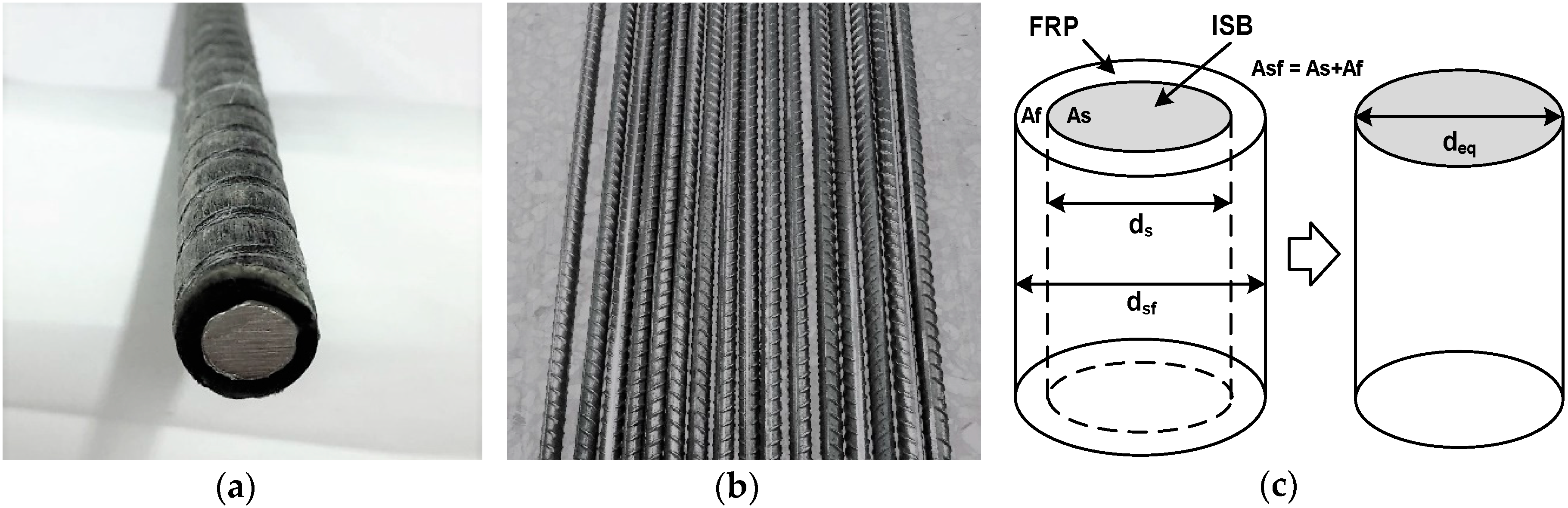
2. Equivalent Flexural Stiffness Principle of the SFCB

For sufficiently slender bars that fail by global flexural buckling, the critical global buckling load (Pcr) can be predicted with the classical Euler formula [31], given by Equation (1).
P c r = π 2 E I / L e f f 2
where E = elastic modulus; I = inertia moment; and Leff = effective length.
The SFCB (Figure 1a) consists of two parts: the ISB (Figure 1b) and FRP, which have different compressive elastic moduli. The elastic modulus of SFCB can change as different fibers are applied to the SFCB. Although only one type of SFCB was studied in this paper, to uniformly distribute the compressive stress or buckling stress among different types or different diameters of the SFCB, the equivalent flexural stiffness of the SFCB was proposed, as in Equation (2), based on the equivalent flexural stiffness principle of the SFCB (Figure 1c).
E s I e q = E s I s + E f I f
where Es = elastic modulus of the ISB; Ieq = equivalent inertia moment of the SFCB; Is = inertia moment of the ISB; If = inertia moment of the FRP; and Ef = elastic modulus of the FRP, which can be obtained through the equivalent axial compressive stiffness equation as in Equation (3).
E s f A s f = E s A s + E f A f
where Esf = elastic modulus of the SFCB, which can be obtained through the mechanical property tests; Asf = cross-sectional area of the SFCB, as shown in Figure 1c; As = cross-sectional area of the ISB; and Af = cross-sectional area of the FRP.
The equivalent diameter (deq) and equivalent slenderness ratio (λeq) of the SFCB can be further calculated as per Equations (4) and (5), respectively.
d e q = E f E s ( d s f 4 d s 4 ) + d s 4 4
λ e q = L d e q
where dsf = diameter of the SFCB and ds = diameter of the ISB, as shown in Figure 1c.
Then, the equivalent critical global buckling load (Pcr-eq) and the squash load (Py) of the SFCB can be calculated as per Equations (6) and (7), respectively.
P c r e q = π 2 E s I e q / L e f f 2
P y = ε s y E s f A s f
where εsy = yield strain of the ISB.

3. Experimental Program

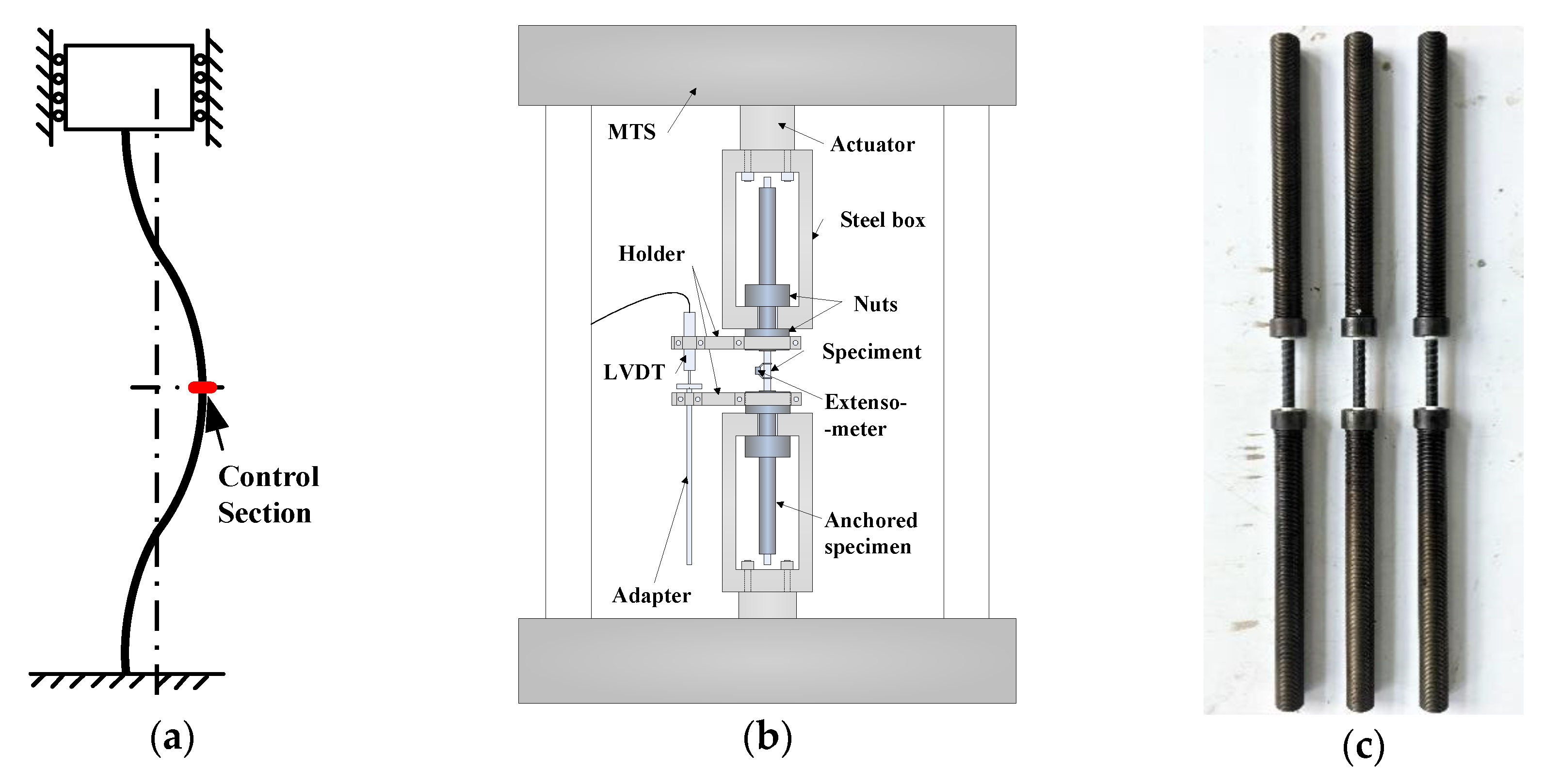
3.1. Test Instruments

All tests were performed on a mechanical testing and simulation machine (MTS). Due to the low shear capacity of the FRP, the SFCB specimens could not be directly clamped and needed to be anchored with an anchoring tube [28]. To achieve the fixed constraint mechanism (Figure 2a) in the tests, a new set of test instruments was developed (Figure 2b), which consisted of an anchored specimen (Figure 2c), steel boxes, nuts, holders, linear variable differential transformer (LVDT) sensors, etc. The installation procedure is as follows: (1) Anchor the specimen into the anchoring tubes; (2) Install the nuts at the ends of the anchoring tubes near the gauge section; (3) Connect the steel boxes to the MTS fatigue testing machine; (4) Insert the specimen (with the anchoring tubes) into the upper and lower steel boxes; (5) Adjust the position of the actuator to eliminate the spaces between the nuts and steel boxes; (6) Install the other two nuts in the steel boxes to fix the anchoring tubes to the steel boxes; and (7) Install the holders, platform, LVDT sensor, and extensometer sensor. Each part of the test instrument was designed to be extremely rigid to achieve the fixed constraint mechanism. The load and displacement were recorded using the MTS and LVDT sensor, respectively, and the load could be further transformed to the stress with the actual cross-sectional area of each specimen when it was under axial tension or axial compression. An extensimeter (gauge length equal to 25 mm) was set in the middle of the specimen, as shown in Figure 2b, to record the strain when the specimen was under axial tension or axial compression. The initial tensile or compressive modulus of each specimen could be further calculated with the strain, recorded by the extensimeter, and the stress, calculated with the load and the actual cross-sectional area of each specimen. The loading system was designed to test the compressive behavior of the SFCB bars without lateral constraints, and the test results could be applied to the SFCB reinforced concrete structures with a weakened concrete cover that was possibly damaged by long-term corrosion or by a natural hazard such as a minor earthquake.

3.2. Specimen Design

Fifty-four specimens were designed where six specimens were used for uniaxial tension and 48 specimens were used for uniaxial compression. The SFCB was composed of a crescent-rib steel bar (with a yield stress and diameter (ds) of 400 MPa and 10 mm, respectively) and an outer FRP (consisting of 48 bundles of basalt fiber (2400-tex) and vinyl epoxy resin). The fabrication method of the SFCB is described in Wu, Wu, Luo, Sun, and Hu [28], and the mechanical properties of the basalt fiber and the vinyl epoxy resin are shown in Table 1. All specimens are listed in Table 2 and Table 3.
Six slenderness ratios were set for the SFCB: 4, 8, 12, 16, 20, and 24. The length of each ISB specimen was the same as the corresponding SFCB for an easy comparison of the test result, while the diameter of the ISB specimen was smaller than the corresponding SFCB specimen, the slenderness ratios of the ISB were slightly higher than those of the corresponding SFCB specimen, and were equal to 4.6, 9.2, 13.8, 18.4, 23, and 27.6. It should be noted that the slenderness ratio was equal to the equivalent slenderness ratio for the SFCB specimens in this paper. The measured diameter (dsf) and equivalent diameter (deq) of the SFCB were equal to 14.6 mm and 11.5 mm, respectively. The linear elastic feature of the FRP makes it impossible to set an initial eccentricity for the SFCB after the SFCB is manufactured. However, the initial eccentricity of SFCB objectively exists either from the initial eccentricity of the ISB or from the manufacturing error, and the effects on the compressive behavior of the SFCB are not included in this paper.

3.3. Loading Program

In the uniaxial tensile and uniaxial compressive tests, a MTS displacement sensor was used to control the loading speed so that the loading stability was not affected by the brittle fracture of the SFCB. The loading strain speed was 0.0002 per second. When the strain reached 0.005, the extensometer sensor was removed to protect it from being damaged. The uniaxial tensile test was conducted until the specimen fractured, whereas the uniaxial compressive test was conducted until the strain of the LVDT sensor reached 0.07.

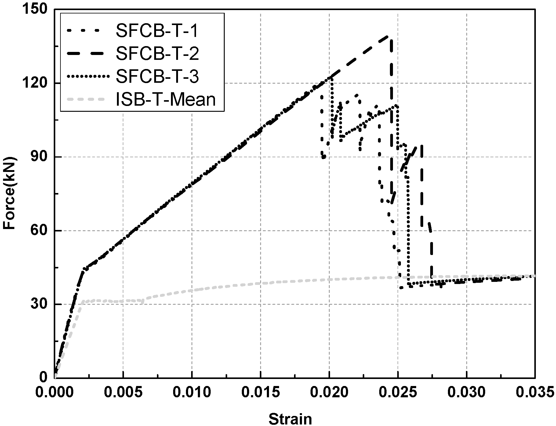
4. Uniaxial Tensile Properties of the SFCB

The results of the uniaxial tensile test are provided in Table 2 and Figure 3, where L = length of the specimen; E+ = initial tensile elastic modulus; E2+ = post-yield tensile modulus; rsf+ = post-yield tensile modulus ratio; σsfy+ = tensile yield stress of the SFCB; σsfu+ = ultimate tensile stress of the SFCB; σsy+ = tensile yield stress of the ISB; σsu+ = ultimate tensile stress of the ISB; and ISB-T-Mean refers to the mean value curve of the ISB specimens. The load-strain curves of the uniaxial tensile tests were applied in this paper to facilitate a comparison between the SFCB and ISB specimens, i.e., noting where the SFCB started yielding at the same tensile strain as the ISB and then exhibited a stable post-yield stiffness until the fracture of the FRP. The stable post-yield stiffness, attributed to the elastic fibers of SFCB, is much higher than that of traditional steel bars (commonly equal to 0), which makes the SFCB more beneficial to the seismic performance of concrete structures than traditional steel bars. After the FRP fractured, the tensile loading was primarily provided by the inner steel bar; therefore, the load-strain curves of the SFCB were essentially consistent with those of the ISB.

5. Uniaxial Compressive Behavior of the SFCB
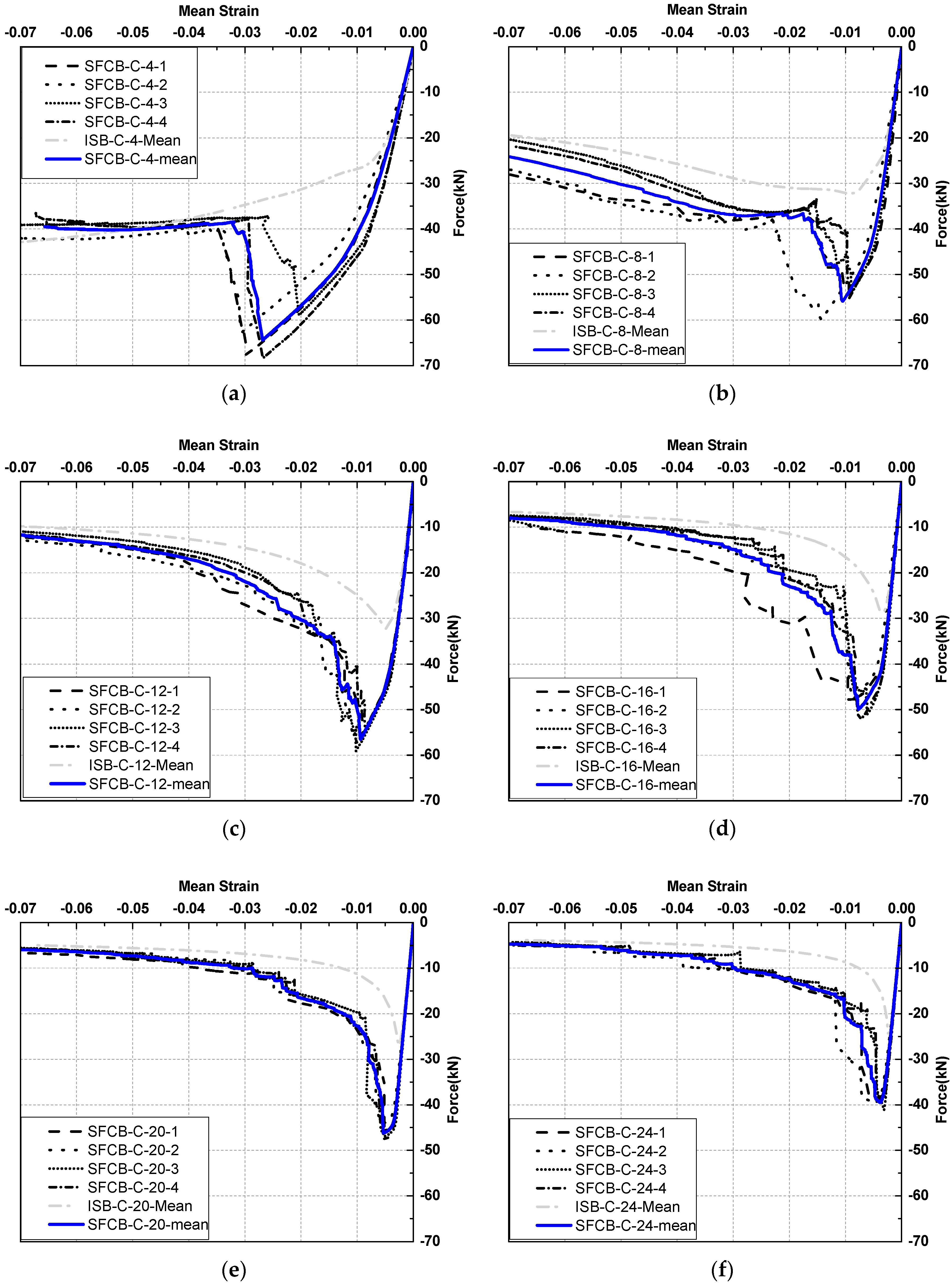
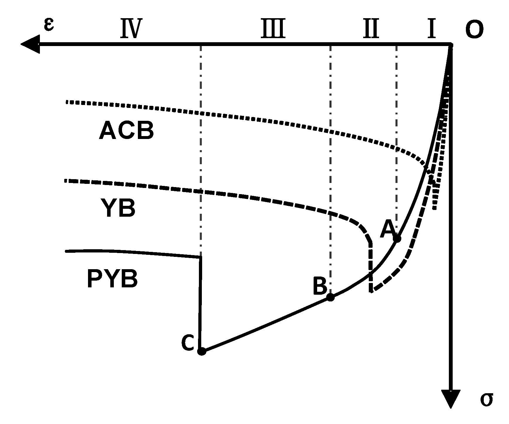
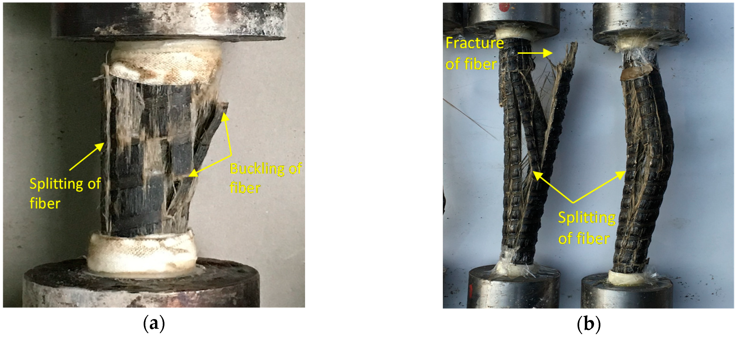
5.1. Test Results

The results of the uniaxial compressive tests are provided in Table 3 and Figure 4, where E = initial compressive elastic modulus; E2 = compressive post-yield modulus; rsf = compressive post-yield modulus ratio; Fsfy = compressive yield load of the SFCB; σsfy = compressive yield stress of the SFCB; Fsfu = ultimate compressive load of the SFCB; σsfu = ultimate compressive stress of the SFCB; Fsu = ultimate compressive load of the ISB; σsu = ultimate compressive stress of the ISB; SFCB-C-4-1 indicates the first SFCB specimen (λeq = 4) under uniaxial compressive loading; ISB-C-8-2 indicates the second ISB specimen (length is equal to that of SFCB-C-8-2) under uniaxial compressive loading; ISB-C-4-mean indicates the mean value curve of four ISB specimens (length is equal to that of SFCB-C-4) under uniaxial compressive loading, as shown in Figure 4a. The average strain in Figure 4 refers to the macroscopic compressive mean strain, which equaled the displacement obtained by the LVDT sensor, as shown in Figure 2b, divided by the length of each specimen.
Due to the different compressive characteristics (Figure 4a–f), the compressive process can be classified into three categories in accordance with the different slenderness ratios, i.e., λeq ≤ 12, 12 < λeq ≤ 20, and λeq > 20, corresponding to the three failure modes, which are post-yield buckling (PYB), yield buckling (YB), and axial compressive buckling (ACB), respectively (Figure 5).
When λeq ≤ 12, the compressive process of the SFCB can be divided into four stages (Figure 5). Since most deformations occur in the middle cross-section of the specimen, this section can be defined as the control section (Figure 2a).
I: Axial compression stage. At the beginning of compression, all specimen cross-sections were under axial compression, and the load-strain curve rose rapidly. With an increase in the strain, a lateral deformation occurred at the control section. Then, the stress condition of the control section gradually transformed from axial compression to eccentric compression, which resulted in a slight decrease in the compressive stiffness (the slope of the load-strain curve) (‘OA’ in Figure 5).
II: Plastic softening stage. Due to the developing lateral deformation, the inner steel section began to yield. The expansion of the yield area resulted in a further decrease in the compressive stiffness and, consequently, resulted in a significant softening stage on the load-strain curve (‘AB’ in Figure 5).
III: Post-yield stiffness stage. With a further expansion of the yield area, nearly the entire inner steel section yielded, and the compressive stiffness of the SFCB was primarily provided by the FRP. Consequently, the compressive stiffness tended to be stable, and the load increased linearly with the strain (‘BC’ in Figure 5). The designable post-yield stiffness stage distinguishes the SFCB from the traditional steel bars by considerably reducing the residual displacement of concrete structures in earthquakes and improving their repairability.
IV: Post-buckling stage. For specimens with a low slenderness ratio (such as λeq = 4), a local buckling was observed due to the splitting or buckling of fibers at random locations, as shown in Figure 6a. A steep decline of the load-strain curve was then observed, as in Figure 4a. For specimens with a high slenderness ratio (such as λeq = 12), an overall buckling of specimen was observed at first, then the load-strain curve began to decline, as in Figure 4c. With the increase of the specimen’s lateral deformation, the fiber will finally split or fracture (Figure 6b).
Although four stages were observed in all of the SFCB specimens when λeq ≤ 12, the compressive characteristics varied slightly for the specimens with different slenderness ratios. In the axial compression stage, the slope of the load-strain curve increased with an increase in the slenderness ratios (Figure 4), which was a result of using the test method based on anchoring. As the loading was transferred through the shear stress of the epoxy, the non-uniform stress distribution occurred in the region close to the anchoring tube, which potentially increased the strain of the outer layer of the specimen in this region and was thus reflected by a decrease in the compressive stiffness. In the post-yield stiffness stage, the linear load-strain curve gradually shortened with an increase in the slenderness ratios as a result of the decreasing ultimate compressive stress. In the post-buckling stage, the FRP became completely invalid after buckling for the specimens with a relatively low slenderness ratio (such as λeq = 4). However, for specimens with a higher slenderness ratio (such as λeq = 12), the FRP was not completely damaged by buckling. Instead, a part of the FRP could continually bear the load until a further split or fracture. The load-strain curve of the specimens with a higher slenderness ratio exhibited a slower approaching speed toward the load-strain curve of the ISB after buckling (Figure 4a–c).
When 12 < λeq ≤ 20, only three stages (Figure 5) including the axial compression stage (I), plastic softening stage (II), and post-buckling stage (IV), were observed during the compressive process. The characteristics of each stage were essentially similar to the specimens with λeq ≤ 12. The primary difference was that the post-yield stiffness stage no longer existed as a result of the advanced buckling in the plastic softening stage and a further decrease in the ultimate compressive stress, which was reduced by an increase in the slenderness ratio. As the slenderness ratio increased, there were only two stages (Figure 5), i.e., the axial compression stage (I) and the post-buckling stage (IV) when λeq > 20. Similar characteristics of each stage were observed during the compressive process when 12 < λeq ≤ 20. The compressive failure mode of SFCB was characterized by the fracture or splitting failure of the outside fibers, which is different from the inelastic buckling failure of a steel bar.

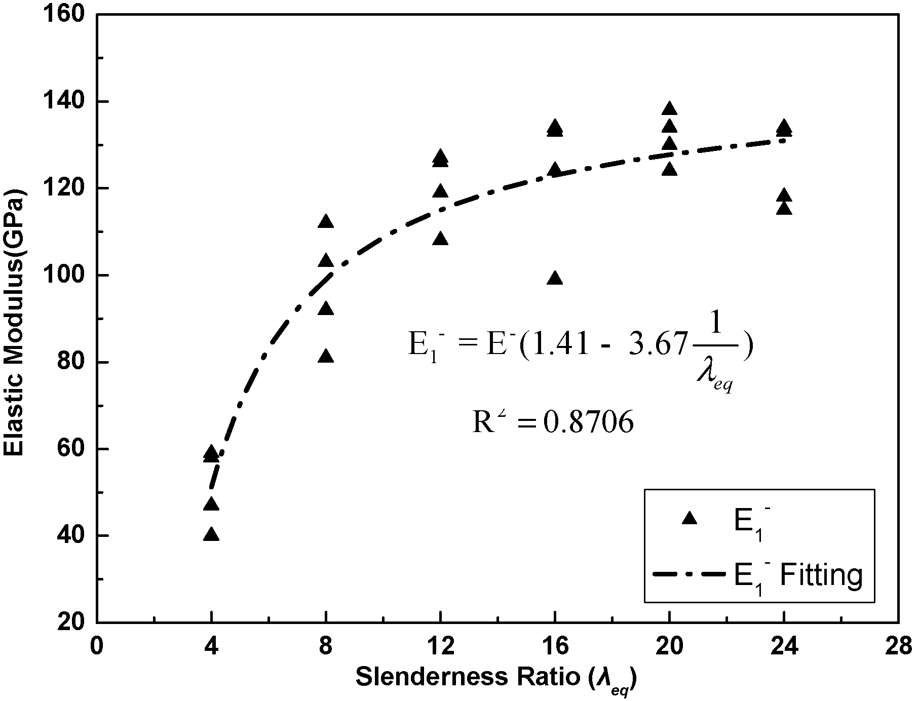
5.2. Initial Compressive Elastic Modulus

The strain values collected by the extensometer sensor were used to calculate the initial elastic modulus. The mean value of the initial tensile elastic modulus (E+) of the SFCB was 109 GPa, whereas the mean value of the initial compressive elastic modulus (E) was in the range of 101 or 106 GPa (Table 2 and Table 3), which indicates that the initial compressive elastic modulus was slightly lower than the initial tensile elastic modulus. This could be attributed to the influences of the initial eccentricity, i.e., the initial eccentricity could reduce the effective projected cross-sectional area of the specimens and could also be interpreted as the cross-sectional area of the specimen equivalently reduced due to the initial eccentricity when the specimen was under axial compression. However, since the differences were relatively small (within 5%), it could be assumed that the initial compressive elastic modulus of the SFCB was essentially the same as its initial tensile elastic modulus. This characteristic of the SFCB distinguished it from the FRP bar, but made it more similar to the steel bar, where the initial elastic modulus of tension and compression were considered to be identical.

5.3. Nominal Initial Compressive Elastic Modulus

The stress state of the anchored specimen under initial compression is similar to the stress state of an unbonded reinforcement in a structure; this reinforcement is typically applied in seismic design to achieve a better seismic performance, especially for the SFCB. Due to the effects of the non-uniform stress distribution condition on the anchored specimens (explained in the Test Results Section), the actual compressive modulus was smaller than the initial compressive elastic modulus, especially when the slenderness ratio was relatively low. Therefore, a nominal initial compressive elastic modulus (E1), which is the ratio of the measured slope of the load-strain curve in the elastic compression stage to the cross-sectional area of the specimen, was proposed to present the characteristics of the elastic compression stage. The results are presented in Figure 7. Using statistical analysis and fitting, the equation for the nominal initial compressive elastic modulus can be presented as Equation (8) as follows:
E 1 = E ( 1.41 3.67 1 λ e q )
It should be noted that Equation (8) can only be applied to the unbonded reinforcement. For the fully anchored reinforcement, the effects of the non-uniform stress distribution condition no longer existed; meanwhile, the nominal initial compressive elastic modulus could be assumed to be equal to the initial compressive elastic modulus.

5.4. Compressive Post-Yield Modulus

As a result of the non-uniform stress distribution condition (explained in the Test Results Section), the compressive post-yield modulus (E2) also increased with an increase in the slenderness radio as well as the nominal initial compressive elastic modulus, and the increasing speed overall exhibited the first quick back slow tendency (Table 3). However, the compressive post-yield modulus ratio (rsf ), which is the ratio of the compressive post-yield modulus to the nominal initial compressive elastic modulus, remained in a lower range (0.17–0.24) despite the variation in the slenderness ratio when the slenderness ratio was larger than 4 (Table 3) and approximately equaled the tensile post-yield modulus ratio (rsf+) (Table 2). Therefore, the compressive post-yield modulus can be simply represented by the tensile post-yield modulus ratio and the nominal initial compressive elastic modulus, which can be provided in Equation (9) as follows:
E 2 = r s f + E 1

5.5. Compressive Yield Load and Stress

The compressive yield load of the SFCB is essentially irrelevant to the slenderness ratio. The mean values of the SFCB compressive yield load remained at 43 kN with the variation in the slenderness ratio, which were generally 19% higher than the mean values of the corresponding squash load, and remained at 36 kN, as shown in Table 3. This indicates that the squash load of the SFCB tends to be conservative when predicting the compressive yield load of the SFCB. In addition, the equivalent critical global buckling load of the SFCB was generally much higher than the corresponding compressive yield load, as shown in Table 3. The mean value of the equivalent critical global buckling load of the SFCB was 151% higher than the corresponding compressive yield load even when the equivalent slenderness ratio of the SFCB reached 20, indicating that an inelastic buckling mechanism was initiated in the SFCB within the range of the slenderness ratio studied in this paper, and that the classic Euler buckling load could not be used to predict the compressive yield load of the SFCB.
The mean values of the compressive yield stress of the SFCB (σsfy) remained at 416 MPa with the variation in the slenderness ratio, which was primarily equal to the tensile yield stress of the SFCB (σsfy+), i.e., 419 MPa. Therefore, the compressive yield stress of the SFCB can be assumed to be in accordance with its tensile yield stress, which is presented in Equation (10) as follows:
σ s f y = σ s f y +

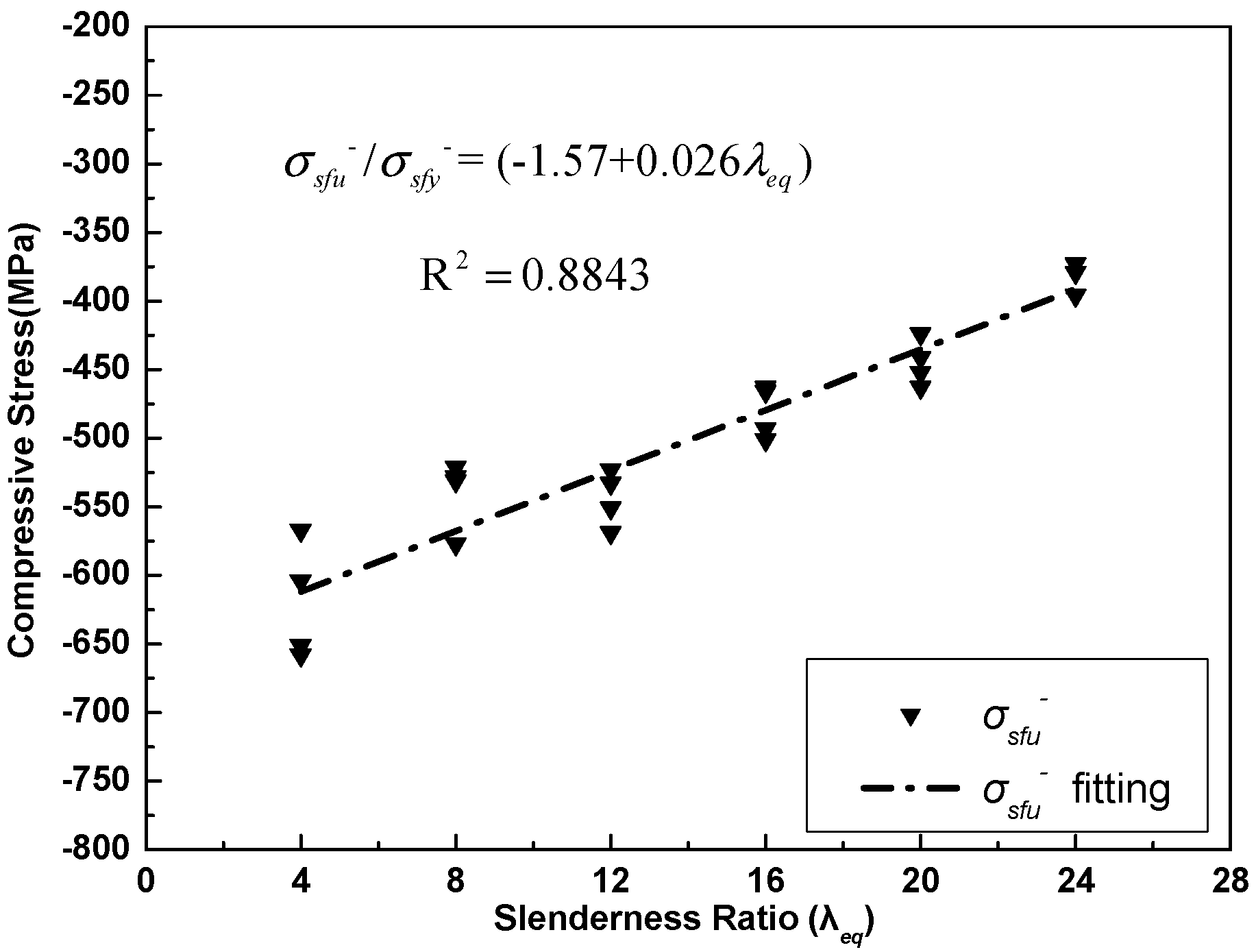
5.6. Ultimate Compressive Load and Stress

The ultimate compressive load of the ISB basically agreed well with the corresponding squash load, especially when the slenderness ratio was relatively low (such as λeq = 9.2). The critical global buckling load of the ISB was still 100% higher than the corresponding ultimate compressive load of the ISB even when its slenderness ratio reached 27.6, as in Table 3, which indicated that the inelastic buckling mechanism also took place on the ISB, within the range of the slenderness ratio studied in this paper.
The mean values of the SFCB ultimate compressive load were higher than the corresponding squash load by 8.3%~77.8% with the variation in the equivalent slenderness ratio, which could be attributed to the elastic fiber of the SFCB restricting the plastic deformation of the ISB after its yielding.
An improvement of approximately 30% was observed when comparing the ultimate compressive stress of the SFCB to the corresponding ultimate compressive stress of the ISB when the slenderness ratio of the SFCB exceeded 8 (Table 3). Additionally, the ultimate compressive stress of the SFCB was inversely proportional to the slenderness ratio, which was similar to the characteristics of the steel bar when under compression [4], and a linear relationship between the ultimate compressive stress of the SFCB, and the slenderness ratio was captured using statistical analysis (Figure 8). The equation of the ultimate compressive stress of the SFCB can be presented in Equation (11) as follows:
σ s f u / σ s f y = ( 1.57 + 0.026 λ e q )

6. Conclusions

In this paper, the compressive properties of the SFCB were presented through comprehensive experimental studies, and the following conclusions were drawn.
(1) A new multipurpose test method was developed and verified through the experimental tests including the tensile and compressive behaviors of the SFCB. The compressive behavior of the SFCB obtained in this paper can be applied to SFCB reinforced concrete structures with a weakened concrete cover, possibly damaged by long-term corrosion or by a natural hazard such as a minor earthquake.
(2) An equivalent slenderness ratio and an equivalent critical global buckling load were proposed based on the equivalent flexural stiffness principle of the SFCB. A four-stage compressive process of the SFCB was observed and defined based on the uniaxial compressive tests including the axial compression stage, plastic softening stage, post-yield stiffness stage, and post-buckling stage. The post-yield stiffness stage and plastic softening stage gradually deteriorated with an increase in the slenderness ratio.
(3) The initial compressive elastic modulus of the SFCB was essentially the same as its initial tensile elastic modulus. This characteristic of the SFCB distinguished it from the FRP bar, but made it more similar to the steel bar. The compressive post-yield modulus and nominal compressive elastic modulus increased proportionally with the slenderness ratios; however, the ratio of these two parameters remained constant.
(4) The compressive yield load of the SFCB was essentially irrelevant to the slenderness ratio. The squash load of the SFCB tended to be conservative when predicting the compressive yield load of the SFC, and the equivalent critical global buckling load of the SFCB was much higher than its corresponding compressive yield load due to the inelastic buckling mechanism of the SFCB. The ultimate compressive stress of the SFCBs varied inversely with the change in the equivalent slenderness ratios. The ultimate compressive load of the SFCB was higher than its corresponding squash load by 8.3%~77.8% with the variation in the equivalent slenderness ratio, which could be attributed to the elastic fiber of the SFCB restricting the plastic deformation of the ISB after its yielding.

Author Contributions

Conceptualization, Y.T.; Methodology, Y.T.; Software, Y.T.; Validation, Y.T., Z.S. and G.W.; Formal Analysis, Y.T.; Investigation, Y.T.; Resources, Y.T.; Data Curation, Y.T.; Writing-Original Draft Preparation, Y.T.; Writing-Review & Editing, Z.S. and G.W.

Funding

This research was funded by the National Key Research and Development Program of China, Grant number [2016YFC0701100]; National Natural Science Foundation of China, Grant number [51778130] and [51525801].

Conflicts of Interest

The authors declare no conflict of interest.

References

  1. Suda, K.; Murayama, Y.; Ichinomiya, T.; Shimbo, H. Buckling behavior of longitudinal reinforcing bars in concrete column subjected to reverse Lateral Loading. In Proceedings of the 11th World Conference on Earthquake Engineering, Acapulco, Mexico, 23–28 June 1996. [Google Scholar]
  2. Dhakal, R.P.; Maekawa, K. Reinforcement stability and fracture of cover concrete in reinforced concrete members. J. Struct. Eng. 2002, 128, 1253–1262. [Google Scholar] [CrossRef]
  3. Monti, G.; Nuti, C. Nonlinear Cyclic Behavior of Reinforcing Bars Including Buckling. J. Struct. Eng.-ASCE 1992, 118, 3268–3284. [Google Scholar] [CrossRef]
  4. Dhakal, R.P.; Maekawa, K. Modeling for postyield buckling of reinforcement. J. Struct. Eng. 2002, 128, 1139–1147. [Google Scholar] [CrossRef]
  5. Bae, S.; Mieses, A.M.; Bayrak, O. Inelastic buckling of reinforcing bars. J. Struct. Eng. 2005, 131, 314–321. [Google Scholar] [CrossRef]
  6. Kashani, M.M.; Crewe, A.J.; Alexander, N.A. Nonlinear stress–strain behaviour of corrosion-damaged reinforcing bars including inelastic buckling. Eng. Struct. 2013, 48, 417–429. [Google Scholar] [CrossRef]
  7. Jiang, C.; Wu, Y.-F.; Dai, M.-J. Degradation of steel-to-concrete bond due to corrosion. Constr. Build. Mater. 2018, 158, 1073–1080. [Google Scholar] [CrossRef]
  8. Kashani, M.M.; Barmi, A.K.; Malinova, V.S. Influence of inelastic buckling on low-cycle fatigue degradation of reinforcing bars. Constr. Build. Mater. 2015, 94, 644–655. [Google Scholar] [CrossRef] [Green Version]
  9. Mander, J.; Panthaki, F.; Kasalanati, A. Low-cycle fatigue behavior of reinforcing steel. J. Mater. Civil Eng. 1994, 6, 453–468. [Google Scholar] [CrossRef]
  10. Massone, L.M.; Moroder, D. Buckling modeling of reinforcing bars with imperfections. Eng. Struct. 2009, 31, 758–767. [Google Scholar] [CrossRef]
  11. Kashani, M.M.; Lowes, L.N.; Crewe, A.J.; Alexander, N.A. Phenomenological hysteretic model for corroded reinforcing bars including inelastic buckling and low-cycle fatigue degradation. Comput. Struct. 2015, 156, 58–71. [Google Scholar] [CrossRef] [Green Version]
  12. Yuan, F.; Chen, M. Numerical Sensing of Plastic Hinge Regions in Concrete Beams with Hybrid (FRP and Steel) Bars. Sensors 2018, 18, 3255. [Google Scholar] [CrossRef]
  13. Tang, Y.; Wu, Z. Distributed long-gauge optical fiber sensors based self-sensing FRP bar for concrete structure. Sensors 2016, 16, 286. [Google Scholar] [CrossRef] [PubMed]
  14. Li, Y.-F.; Meda, H.; Chen, W.J.S. The Design and Analysis of Internally Stiffened GFRP Tubular Decks—A Sustainable Solution. Sustainability 2018, 10, 4538. [Google Scholar] [CrossRef]
  15. Cascone, S.M.; Sapienza, V.; Lionti, I.; Porto, S.M.C.J.S. Fiber-reinforced polymer nets for strengthening lava stone masonries in historical buildings. Sustainability 2016, 8, 394. [Google Scholar] [CrossRef]
  16. Wu, Z.; Wang, X.; Wu, G. Advancement of structural safety and sustainability with basalt fiber reinforced polymers. In Proceedings of the 6th International Conference on FRP Composites in Civil Engineering, CICE 2012, Rome, Italy, 13–15 June 2012; pp. 15–29. [Google Scholar]
  17. ACI. Guide for the Design and Construction of Concrete Reinforced with FRP Bars; ACI 440 1R-06; ACI: Detroit, MI, USA, 2006; Available online: http://www.radyab.co/content/media/article/13.pdf (accessed on 13 January 2017).
  18. Malvar, L.J. Tensile and bond properties of GFRP reinforcing bars. Mater. J. 1995, 92, 276–285. [Google Scholar]
  19. Wu, Z.; Wang, X.; Wu, G. Basalt FRP composite as reinforcements in infrastructure. In Proceedings of the 17th Annual International Conference on Composites/Nano Engineering (ICCE-17), Honolulu, HI, USA, 26 July–1 August 2009; pp. 21–24. [Google Scholar]
  20. Wu, W.-P. Thermomechanical properties of fiber reinforced plastic (FRP) bars. Diss. Abstr. Int. (USA) 1992, 52, 292. [Google Scholar]
  21. Nanni, A.; Henneke, M.J.; Okamoto, T. Tensile properties of hybrid rods for concrete reinforcement. Constr. Build. Mater. 1994, 8, 27–34. [Google Scholar] [CrossRef]
  22. Saikia, B.; Thomas, J.; Ramaswamy, A.; Rao, K.N. Performance of hybrid rebars as longitudinal reinforcement in normal strength concrete. Mater. Struct. 2005, 38, 857–864. [Google Scholar] [CrossRef] [Green Version]
  23. Sun, Z.Y.; Wu, G.; Wu, Z.S.; Zhang, M.; Hu, X.Q. Experimental study on the bond behavior between steel fiber composite bar (SFCB) and concrete. Earthq. Resist. Eng. Retrofit. 2009, 31, 21–27. [Google Scholar]
  24. Wang, X.; Jiang, L.; Shen, H.; Wu, Z. Long-Term Performance of Pultruded Basalt Fiber Reinforced Polymer Profiles under Acidic Conditions. J. Mater. Civil Eng. 2018, 30, 04018096. [Google Scholar] [CrossRef]
  25. Ibrahim, A.I.; Wu, G.; Sun, Z.-Y. Experimental Study of Cyclic Behavior of Concrete Bridge Columns Reinforced by Steel Basalt-Fiber Composite Bars and Hybrid Stirrups. J. Compos. Constr. 2016, 21, 04016091. [Google Scholar] [CrossRef]
  26. Sun, Z.; Yang, Y.; Qin, W.; Ren, S.; Wu, G. Experimental study on flexural behavior of concrete beams reinforced by steel-fiber reinforced polymer composite bars. J. Reinf. Plast. Comp. 2012, 31, 1737–1745. [Google Scholar] [CrossRef]
  27. Sun, Z.-Y.; Wu, G.; Wu, Z.-S.; Zhang, J. Nonlinear Behavior and Simulation of Concrete Columns Reinforced by Steel-FRP Composite Bars. J. Bridge Eng. 2013, 19, 220–234. [Google Scholar] [CrossRef]
  28. Wu, G.; Wu, Z.-S.; Luo, Y.-B.; Sun, Z.-Y.; Hu, X.-Q. Mechanical properties of steel-FRP composite bar under uniaxial and cyclic tensile loads. J. Mater. Civil Eng. 2010, 22, 1056–1066. [Google Scholar] [CrossRef]
  29. Wu, G.; Wu, Z.; Luo, Y.; Wei, H. A new reinforcement material of steel fiber composite bar (SFCB) and its mechanics properties. In Proceedings of the 9th International Symposium on Fiber Reinforced Polymer Reinforcement for Reinforced Concrete Structures (FRPRCS-9), Sydney, Australia, 13–15 July 2009. [Google Scholar]
  30. Sun, Z.; Tang, Y.; Luo, Y.; Wu, G.; He, X. Mechanical Properties of Steel-FRP Composite Bars under Tensile and Compressive Loading. Int. J. Polym. Sci. 2017, 2017, 5691278. [Google Scholar] [CrossRef]
  31. Euler, L. Methodus Inveniendi Lineas Curvas Maximi Minimive Proprietate Gaudentes sive Solutio Problematis Isoperimetrici Latissimo Sensu Accepti; Springer Science & Business Media: Berlin, Germany, 1952; Volume 1. [Google Scholar]
Figure 1. Specimens and equivalent flexural stiffness principle: (a) SFCB; (b) ISB; and (c) Equivalent flexural stiffness principle.
Sustainability 11 01118 g001
Figure 2. Loading system. (a) Fixed constraint mechanism; (b) Test Instrument; and (c) Anchored specimen.
Sustainability 11 01118 g002
Figure 3. Load-strain curves of the uniaxial tensile tests.
Sustainability 11 01118 g003
Figure 4. Load-strain curves of the uniaxial compressive tests: (a) λeq = 4; (b) λeq = 8; (c) λeq = 12; (d) λeq = 16; (e) λeq = 20; and (f) λeq = 24.
Sustainability 11 01118 g004
Figure 5. Compressive processes and failure modes of the SFCB under uniaxial compressive loading.
Sustainability 11 01118 g005
Figure 6. Failure examples of the SFCB under uniaxial compressive loading.
Sustainability 11 01118 g006
Figure 7. E1 analysis and fitting for the uniaxial compressive tests.
Sustainability 11 01118 g007
Figure 8. σsfu analysis and fitting for the uniaxial compressive tests.
Sustainability 11 01118 g008
Table 1. Mechanical properties of SFCB components.
TypeElastic Modulus (GPa)Tensile Strength (MPa)Density (g/cm3)Diameter (μm)Elongation Rate (%)
Basalt fiber9022502.63132.5
vinyl epoxy resin3.6951.066.1
Table 2. Test results of the uniaxial tensile tests (L = 600 mm).
SpecimenλeqE+ (GPa)E2+ (GPa)rsf+ (E2+/E)σsfy+ (MPa)σsfu+ (MPa)σsy+ (MPa)σsu+ (MPa)
SFCB-T-152112 22 0 413 1162
SFCB-T-252108 22 0 419 1348
SFCB-T-352107 23 0 426 1181
SFCB-T-Mean521092204191230
ISB-T-160189 400 528
ISB-T-260191 400 533
ISB-T-360190 400 530
ISB-T-Mean60190400530
Table 3. Test results of the uniaxial compressive tests.
SpecimenL (mm)Leff (mm)λeqE (GPa)E2 (GPa)rsf (E2+/E)Fsfy (kN)σsfy (MPa)Fsfu (kN)σsfu (MPa)Fsu (kN)σsu (MPa)Py (MPa)Pcr-eq (MPa)Failure Mode
SFCB-C-4-14623495 11 0.12 −44 −426 −68 −651 −33 PYB
SFCB-C-4-24623497 10 0.10 −43 −410 −63 −604 −34 PYB
SFCB-C-4-346234107 12 0.11 −42 −408 −59 −567 −38 PYB
SFCB-C-4-446234103 11 0.11 −44 −424 −68 −658 −36 PYB
SFCB-C-4-Mean46234101110.11−43−417−64−620−36
SFCB-C-8-192468111 19 0.17 −43 −416 −55 −528 −39 −768 PYB
SFCB-C-8-29246880 17 0.21 −45 −438 −60 −577 −28 −295 PYB
SFCB-C-8-392468103 21 0.20 −42 −406 −54 −521 −36 −646 PYB
SFCB-C-8-49246894 23 0.24 −43 −417 −55 −531 −33 −509 PYB
SFCB-C-8-Mean92468103200.21−43−419−56−539−36−646
SFCB-C-12-11386912110 24 0.22 −45 −433 −55 −533 −39 −335 PYB
SFCB-C-12-21386912109 21 0.19 −43 −416 −57 −551 −38 −328 PYB
SFCB-C-12-31386912104 22 0.21 −43 −415 −59 −569 −37 −294 PYB
SFCB-C-12-41386912101 24 0.24 −44 −425 −54 −523 −36 −274 PYB
SFCB-C-12-Mean1386912106230.22−44−422−56−544−37−307
SFCB-C-16-11849216111 −41 −394 −48 −466 −39 −192 YB
SFCB-C-16-21849216100 22 0.22 −41 −398 −48 −463 −35 −150 YB
SFCB-C-16-31849216109 20 0.18 −42 −404 −51 −493 −38 −184 YB
SFCB-C-16-41849216105 22 0.21 −43 −419 −52 −501 −37 −169 YB
SFCB-C-16-Mean1849216106210.20−42−404−50−481−37−173
SFCB-C-20-123011520109 −44 −426 −48 −463 −38 −118 YB
SFCB-C-20-22301152099 −41 −393 −44 −424 −35 −94 YB
SFCB-C-20-323011520110 −44 −427 −47 −452 −39 −120 YB
SFCB-C-20-423011520103 -44 −423 −46 −441 −36 −103 YB
SFCB-C-20-Mean23011520105−43−417−46−445−37−108
SFCB-C-24-12761382498 −39 −373 −35 −63 ACB
SFCB-C-24-22761382496 −39 −379 −34 −60 ACB
SFCB-C-24-327613824105 −41 −396 −37 −75 ACB
SFCB-C-24-427613824104 −39 −373 −37 −73 ACB
SFCB-C-24-Mean27613824101−39−380−36−68
ISB-C-4-146234.6188 −31
ISB-C-4-246234.6189 −31
ISB-C-4-346234.6188 −31
ISB-C-4-446234.6190 −31
ISB-C-4-Mean46234.6189−31
ISB-C-8-192469.2191 −33 −415 −31 −434
ISB-C-8-292469.2190 −32 −413 −31 −434
ISB-C-8-392469.2188 −32 −404 −31 −434
ISB-C-8-492469.2187 −33 −417 −31 −434
ISB-C-8-Mean92469.2189−32−412−31−434
ISB-C-12-11386913.8188 −33 −423 −31 −193
ISB-C-12-21386913.8187 −32 −408 −31 −193
ISB-C-12-31386913.8189 −34 −427 −31 −193
ISB-C-12-41386913.8191 −32 −402 −31 −193
ISB-C-12-Mean1386913.8189−33−415−31−193
ISB-C-16-11849218.4188 −30 −377 −31 −109
ISB-C-16-21849218.4189 −29 −366 −31 −109
ISB-C-16-31849218.4187 −28 −354 −31 −109
ISB-C-16-41849218.4188 −31 −391 −31 −109
ISB-C-16-Mean1849218.4188−29−372−31−109
ISB-C-20-123011523188 −29 −365 −31 −69
ISB-C-20-223011523189 −28 −357 −31 −69
ISB-C-20-323011523191 −26 −332 −31 −69
ISB-C-20-423011523189 −26 −335 −31 −69
ISB-C-20-Mean23011523189−27−347−31−69
ISB-C-24-127613827.6192 −24 −302 −31 −48
ISB-C-24-227613827.6190 −25 −317 −31 −48
ISB-C-24-327613827.6189 −27 −348 −31 −48
ISB-C-24-427613827.6187 −29 −364 −31 −48
ISB-C-24-Mean27613827.6190−26−333−31−48

