Article

A Sensorless Control Strategy Exploiting Error Compensation for Permanent Magnet Synchronous Motor Based on High-Frequency Signal Injection

by
Zhouji Li
1,
Mohammad Nizamuddin Inamdar
1,* and
Yongwei Wang
2,3
1
Faculty of Engineering & Built Environment, Lincoln University College, Petaling Jaya 47301, Malaysia
2
Faculty of Intelligent Manufacturing, Luoyang Institute of Science and Technology, Luoyang 471023, China
3
International Joint Laboratory of Composite Tools and Precision Machining, Luoyang 471023, China
*
Author to whom correspondence should be addressed.
World Electr. Veh. J. 2025, 16(5), 261; https://doi.org/10.3390/wevj16050261
Submission received: 26 March 2025 / Revised: 2 May 2025 / Accepted: 4 May 2025 / Published: 7 May 2025

Abstract

:
A permanent magnet synchronous motor (PMSM) is typically run at low speed with a sensorless control system using a high-frequency signal injection method. However, current harmonic and gain errors compromise rotor position observation accuracy. In this paper, we analyze the reasons for rotor observation angle error and propose a new rotor position observer with error compensation. This new sensorless control tool obtains the compensation error angle by extracting the negative high-frequency current in order to estimate the rotor position information accurately. The experimental results show that the error compensation strategy proposed in this paper can improve the accuracy of rotor position observation and achieve operation of the PMSM in both steady-state working conditions and dynamic working conditions at low speed.

1. Introduction

A permanent magnet synchronous motor (PMSM) is a drive system with high power density and efficiency and fast dynamic response; PMSMs are widely used in home appliances, robots, electric vehicles, and other industrial fields [1,2]. It is necessary to obtain accurate rotor position information to achieve vector control of a PMSM. The conventional method employs position sensors to obtain rotor position information. However, this approach is associated with increased manufacturing costs, diminished operational reliability, and restrictions in applicable scenarios. To solve the above problems, researchers have increasingly focused on position sensorless vector control techniques for PMSMs [3,4].
Sensorless control approaches include the fundamental wave model method, based on observing the value of the back electromotive force, and the high-frequency signal injection technique, according to salient characteristics [5,6,7,8,9,10]. This method is used in the medium–high-speed range when a motor system has a high signal-to-noise ratio. Other commonly used control techniques include the sliding-mode observer method [11,12,13], model reference adaptive method [14,15,16], Kalman filter method [17,18], etc. When a motor is running in the zero–low-speed range, the salient features of the motor are used to achieve motor control using factors such as inverter non-linearity, making the counter-potential amplitude small and difficult to detect accurately. By injecting a high-frequency voltage signal, the high-frequency current response is excited, and by processing this, the rotor position information is then extracted. According to the type of injected signals, high-frequency signal injection methods can be classified into high-frequency pulsed signal injection [19,20], high-frequency rotary signal injection [21,22,23], and high-frequency square-wave signal injection [24,25].
The high-frequency pulsed injection process involves injecting high-frequency voltage, extracting the position error signal, and estimating the rotor position. The position error signal contains information about the difference between the actual and estimated rotor positions. Reducing the estimation error is the key to calculating the rotor position, directly affecting the motor’s dynamic performance and steady-state accuracy [26,27,28,29,30,31]. The conventional high-frequency pulsed injection method necessitates the utilization of filters for high-frequency current extraction, the demodulation function, and filtering by a phase-locked loop. This approach increases the complexity of the algorithm implementation and introduces phase delay in the demodulation process. The authors of [32] proposed a method to improve error signal extraction using a dual-frequency notch filter, improving system bandwidth and filtering capability. However, in this method it is still necessary to use a low-pass filter to remove the n-th harmonics of the inverter switching frequency due to the direct modulation of the current on the quadrature axis, which increases the system delay. The researchers in [33] proposed demodulating current based on the recursive discrete Fourier transform to overcome the delay defect of a filter, but this increases the hardware burden. In the study in [34], high-frequency square-wave injection extracted a signal without a low-pass filter. The results showed that the dynamic performance was better, but the inductive loss and harmonics increased with the increase in injection frequency. The authors of [35] proposed an improved extraction strategy involving a cascading second-order general integrator and dual-frequency notch filter, which solves the problems of low filtering accuracy and slow dynamic response in error signal extraction using the traditional method. However, this approach neglects the influence of non-ideal factors on the precision of position estimation, which has implications for the reliability and accuracy of the motor in practical applications.
Non-ideal factors such as asymmetry in the motor parameters and detection errors in the current sensor can lead to more obvious harmonic estimation errors in the high-frequency injection method in practical applications; thereby, these factors can cause further problems such as the inaccurate decoupling of the components in the direct and quadrature axes, phase current waveform distortion, and torque and speed fluctuations. The researchers in [36], considering the magnetic field cross-saturation effect, proposed an offline parameter identification method based on pulsed voltage injection, which can effectively obtain parameter information such as inductance and magnetic flux; however, due to the complexity of motor system operating conditions, it is challenging to simulate all operating conditions in offline testing. In the study in [37], the non-linearity of the inverter was taken into account, and the identification of the inductor parameters was achieved through high-frequency signal injection. In the research in [38], the dead zone of the inverter resulted in the incorporation of the sixth harmonic component into the estimated position. To address this issue, an adaptive filter was employed to eliminate the harmonic component in the back electromotive force, thereby compensating for the effect of the dead zone. In [39], a closed-loop position error compensation method was proposed which involves using the error eigenvalue for the purpose of regulating the rotor position in a closed loop. This is achieved according to the eigenvalue component of the rotor position error on the direct axis. The method is simple to implement but depends on the inductor parameters. In the study in [40], a double phase-locked loop was used to phase-lock the delayed reconstructed signal twice to compensate for the position error. The authors of [41,42] compensated position error by tracking the minimum current. This method is simple to implement and independent of any parameter, which means that it is robust but leads to current jitter in the steady state, which affects the stability of the system. The above studies provided effective compensation schemes to address the estimated position error due to non-ideal factors in the low-speed control of a PMSM.
The accuracy of estimation of the rotor position is a significant measure of the performance of sensorless control systems. The inverter non-linear effect and sensor detection errors in the current affect the accuracy of the estimation of the rotor position. Indeed, these non-ideal factors result in obvious harmonic estimation errors in the practical application of the high-frequency signal injection method, which in turn cause the waveform distortion of the phase current as well as problems with the motor torque and speed fluctuations. In this paper, based on the implementation of the PMSM position sensorless control using the pulsed high-frequency voltage injection method, a compensation strategy is designed to address the main non-ideal factors. The rotor estimation error, which is obtained by extracting the negative high-frequency current, uses the estimated rotor position angle to improve the accuracy of the estimation of the rotor position. The experimental results demonstrate that the proposed method enhances the estimated errors of the rotor position, thereby significantly improving the observation accuracy of the observer and enabling the motor to operate in a satisfactory condition at low speeds.

2. Mathematical Mode for High-Frequency Pulsed Signal Injection Method

The sensorless control of a PMSM is often achieved by using the high-frequency pulsed signal injection method at low speed, which is based on injecting a high-frequency sinusoidal signal into the direct axis in the estimated rotor rotational coordinate system, thus extracting a high-frequency pulsating current response signal containing rotor information and obtaining rotor position and speed information. Figure 1 shows a block diagram of the high-frequency pulsed signal injection method for a PMSM sensorless control system. Figure 2 shows the definitions of angles and axes, which involve the stationary coordinate system α β , the rotating coordinate system d q , and the estimated rotating coordinate system D Q . θ e is the actual rotor position angle and θ e s t is the estimated rotor position angle, and the difference between them is the estimated rotor position error angle θ .
In order to simplify the mathematical modeling, some assumptions are made: The cogging effect and the saturation effect are neglected, and three-phase windings are completely symmetrical. The voltage equation of the internal permanent magnet synchronous motor (IPMSM) in the rotating coordinate system is as follows:
u d u q = R s ω e L q ω e L d R s i d i q + L d 0 0 L q d d t i d i q + 0 ω e ψ f
where u d , u q are the stator voltage, i d , i q are the stator current, L d , L q are the stator inductance, R s is the stator resistance, ω e is the electrical rotor speed, and ψ f is the magnetic linkage flux.
It is generally accepted that the frequency of the injection signal is significantly higher than the fundamental frequency of the motor. In such cases, it is possible to simplify the IPMSM model as an RL circuit. When the stator resistance is negligible, the relationship between the high-frequency voltage and current of the IPMSM becomes
d d t i d h i q h = 1 L d 0 0 1 L q u d h u q h
where u d h , u q h are the components of the high-frequency voltage and i d h , i q h are the components of the high-frequency current in the rotating coordinate system.
The coordinate transformation matrix of the rotating coordinate system and estimated coordinate system is
T d q / D Q = cos θ sin θ sin θ cos θ
Therefore, the high-frequency voltage and current are related in the estimated rotating coordinate system:
d d t i D h i Q h = cos θ sin θ sin θ cos θ 1 L d 0 0 1 L q cos θ sin θ sin θ cos θ u D h u Q h
where u D h , u Q h are the components of the high-frequency voltage and i D h , i Q h are the components of the high-frequency current in the estimated rotating coordinate system.
The high-frequency pulsating voltage signal injected into the D-axis in the estimated rotating coordinate system is
u D i n j u Q i n j = U i c o s ω i t 0
where U i is the amplitude and ω i is the frequency of the injected signal. The digital system uses a single-sample or a update mode, which means that the sampling period T s is the same as the pulse width modulation (PWM) carrier period T p w m . The injected high-frequency voltage signal T i is twice the sampling period T s .
Substituting Equation (5) into Equation (4) gives
d d t i D h i Q h = 1 L 2 L 2 L + L   c o s 2 θ L   s i n 2 θ L   s i n 2 θ L L   c o s 2 θ U i c o s ω i t 0
where L = ( L d + L q ) / 2 is the average inductance, and L = ( L q L d ) / 2 is the difference inductance.
From Equation (6), the high-frequency current can be simplified as
i D h = U i s i n ω i t L 2 L 2 ( L + L   c o s 2 θ ) i Q h = U i s i n ω i t L 2 L 2 L   s i n 2 θ
As shown in Equation (7), the amplitude of i Q h , i D h contains information about the estimated rotor position error, which can be used to calculate the position. When the estimated rotor position error angle is zero, the high-frequency current on the Q-axis is equal to zero, so i D h can be utilized as the input signal to observe the rotor position and speed. If the estimated rotor position error is very small, i D h is
f θ = U i L 2 ω i ( L 2 L 2 ) s i n 2 θ = K θ
where K = U i L / 2 ω i ( L 2 L 2 ) .
The observer obtains the rotor position information through the phase-locked loop (PLL) to control f θ r in order for it to converge to 0, and then the estimated rotor position error angle ∆θ is close to zero. A control block diagram is shown in Figure 3.
For the high-frequency signal injection method of PMSM sensorless control systems, several digital filters, such as the band-pass filter (BPF), high-pass filter (HPF), and low-pass filter (LPF), are usually required to extract the high-frequency response current from the sampling current. When extracting high-frequency current signals, a second-order BPF is often used, whose transfer function is expressed as
H s = 2 ξ ω 0 s s 2 + 2 ξ ω 0 s + ω 0 2
where ξ is the damping coefficient and ω 0 is the center frequency.
These filters affect the amplitude and phase of the high-frequency signal during the process of extraction of the negative high-frequency current, which will ultimately affect the estimation accuracy of the rotor position if not effectively compensated by the phase position angle. The high-frequency current which is extended by BPF on the estimated rotating coordinate is as follows:
i D Q h = I h p e j ω h ω ^ r t + I h n e j ω h + 2 ω r ω ^ r t
where ω h is the frequency of the injection high-frequency voltage, ω r is the rotor speed, ω ^ r is the estimated rotor speed, I h p is the amplitude of the positive-phase high-frequency current, and I h n is the amplitude of the negative-phase high-frequency current. When the estimated rotor position error angle θ approaches zero, the frequency of the positive-phase high-frequency current is equal to the negative-phase high-frequency current.
The phase–frequency curve of the second-order BPF in a Bode plot is shown in Figure 4. Where ω h is 1000 Hz and the frequency range of the BPF is set to 987 Hz to 1018 Hz. The phase delay of the positive- and negative-phase high-frequency currents is 4.71°. Considering the phase delay of the filters used in the control system, Equation (10) can be expressed as
i D Q h = I h p e j ω h ω ^ r t + φ p b + I h n e j ω h + 2 ω r ω ^ r t φ p b
where φ p b and φ p b are the phase delay of the positive- and negative-phase high-frequency currents. There will be an angular error of φ p b /2 between the estimated rotor position and the actual rotor position if no compensation measures are implemented.

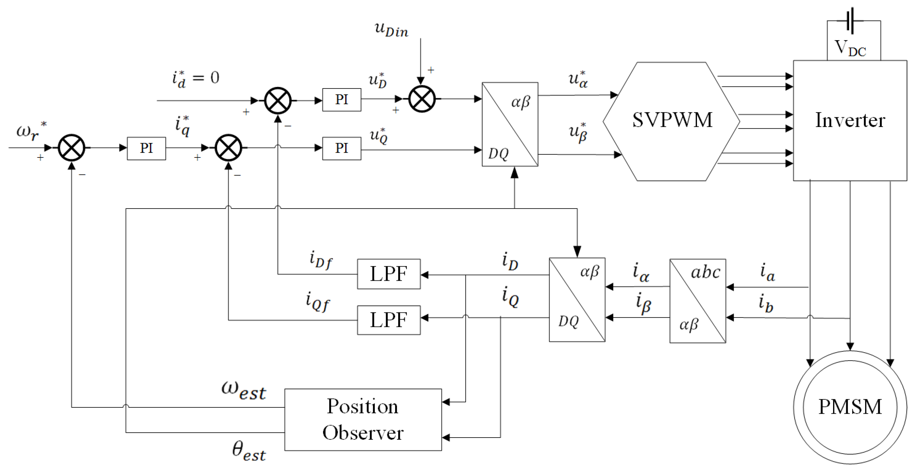
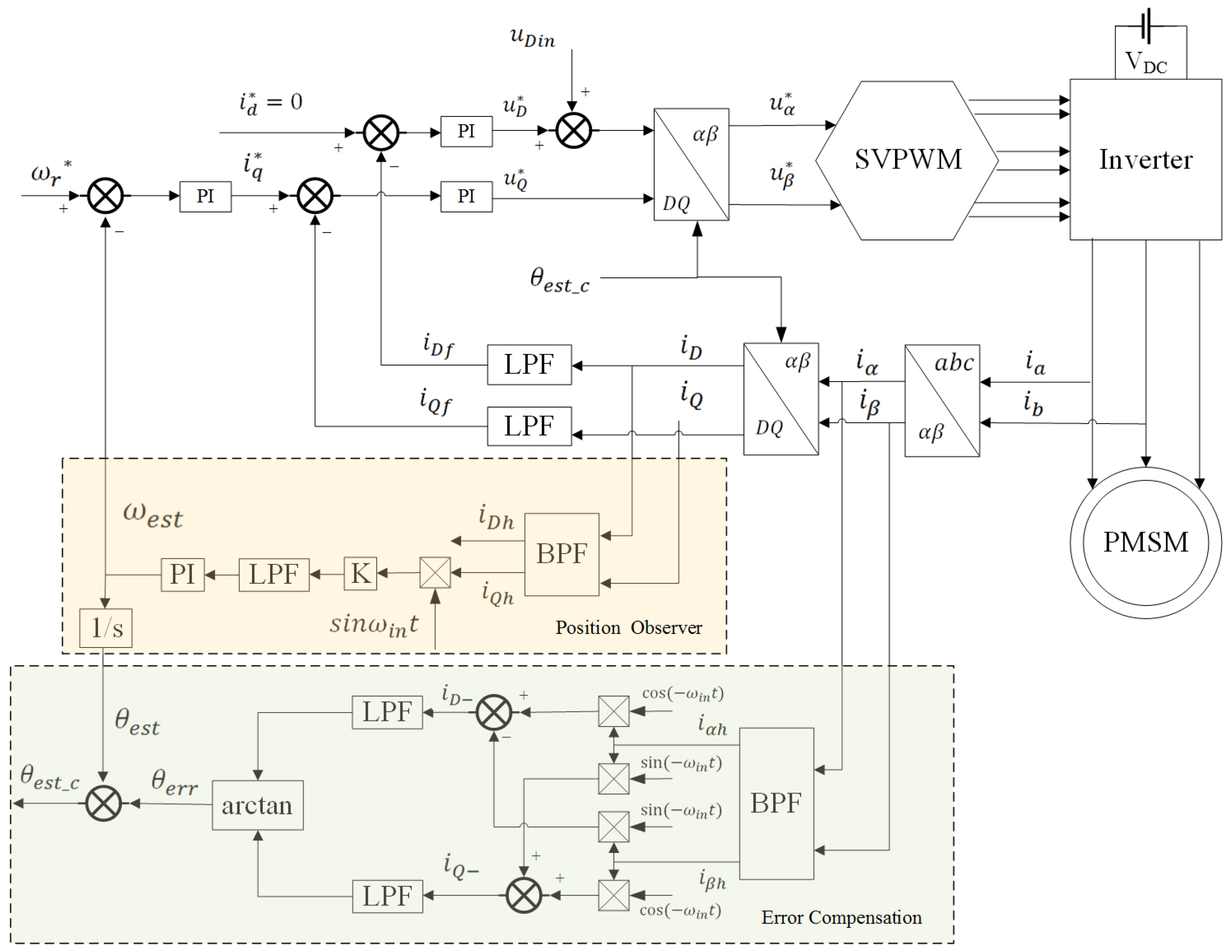
3. Proposed Sensorless Control Strategy for Rotor Position Error Compensation in High-Frequency Signal Injection

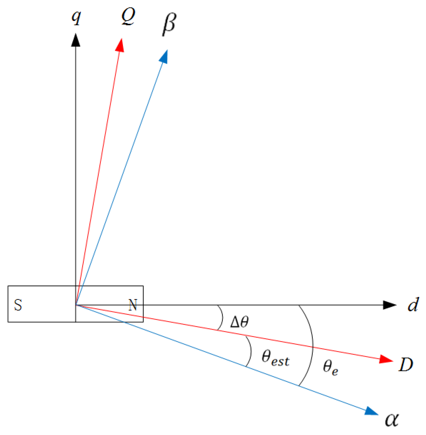
3.1. Analysis of Estimated Rotor Position Error in High-Frequency Signal Injection

The accuracy of rotor position estimation determines the performance of the control system in a PMSM. However, the rotor position information estimated based on the model method includes the current harmonics and the current gain error generated by the actual current through the sensor and the sampling conditioning circuit. These errors affect the results of the coordinate transformation and therefore decoupling is inaccurate, which causes the motor operation to deteriorate.

3.1.1. Cross-Saturation Effect

The cross-saturation effect also causes the estimated rotor position error on the high-frequency signal injection method. Typically, the cross-saturation effect increases with increasing load. If considering the cross-saturation effect, the pulsed high-frequency voltage signal in the DQ estimated rotating coordinate system is expressed as
u D in j u Q inj = U i c o s ω i t 0 = cos θ sin θ sin θ cos θ L d h L d q h L d q h L q h cos θ sin θ sin θ cos θ d d t i D h i Q h
The pulsed high-frequency voltage signal in the DQ estimated rotating coordinate system is expressed as
i D h = U i s i n ω i t 2 ω i L d h L q h L d q h 2 { Σ L + Σ L 2 + L d q h 2 [ cos 2 θ + θ m sin 2 θ + θ m ] } i D h = U i s i n ω i t 2 ω i L d h L q h L d q h 2 { Σ L + Σ L 2 + L d q h 2 [ cos 2 θ + θ m + sin 2 θ + θ m ] }
where θ m = a r c t a n ( L d q h / Σ L ) . θ m is the cross-saturation angle, which is related to the motor parameters; θ m = a r c t a n   ( L d q h / Σ L ) , the average self-inductance Σ L = ( L d h + L q h ) / 2 , and the difference self-inductance Σ L = ( L q h L d h ) / 2 .
From above equation, the amplitude of the high-frequency current includes information about the estimated rotor position error in the DQ estimated rotating coordinate system. The estimated speed and position are obtained by adjusting the equivalent position error ε = 2 θ + θ m to zero by PLL. Therefore, considering the cross-saturation effects, the estimated rotor position is expressed as
θ = θ m 2 = 0.5 a r c t a n L d q h Σ L
The asymmetry of the motor parameters is the cause of the difference self-inductance. Consequently, the estimated rotor position error manifests as the second-order harmonic, as illustrated in Figure 5. It is noteworthy that the greater the difference, the more significant the harmonic amplitude.

3.1.2. Current Harmonic Errors

Current harmonics arise from time harmonics, introduced by non-linear factors such as dead band effects or tube voltage drops in the inverter circuit, and space harmonics, introduced by air-gap magnetic field distortions due to motor design.
The non-linear characteristics of the inverter result in the distortion of the output voltage of the bridge arm of the inverter, as well as time harmonics in the output current and voltage. The frequency of time harmonics includes third, fifth, and seventh orders, and their amplitude usually depends on the operating mode, switching frequency, and load of the inverter.
The asymmetrical geometry of the stator and rotor, the variability in the magnetic material in the motor, and machining accuracy and assembly errors in the motor’s manufacturing process lead to distortion of the magnetic field in the air gap. These aspects lead to the generation of space harmonics, which have frequencies of the third, fifth, and seventh orders.
Because of time harmonics and space harmonics, the actual output current includes third, fifth, and seventh harmonics. The high-frequency pulsed signal is
u D h u Q h = 4 U i π sin ω i t + 1 3 sin 3 ω i t + 1 5 sin 5 ω i t + 1 7 sin 7 ω i t 0
Substituting Equation (15) into Equation (4) gives the high-frequency response signal in the estimated rotating coordinate system, which includes the frequency of the fundamental wave ω i and the components of the third, fifth, and seventh harmonics.
i D h = 1 L 2 L 2 4 U i π L + Lcos 2 θ ω i cos ω i t L + Lcos 2 θ 3 ω i cos 3 ω i t L + Lcos 2 θ 5 ω i cos 5 ω i t L + Lcos 2 θ 7 ω i cos 7 ω i t i Q h = 1 L 2 L 2 4 U i π Lsin 2 θ 1 ω 0 cos ω i t 1 3 ω i cos 3 ω i t 1 5 ω i cos 5 ω i t 1 7 ω i cos 7 ω i t
According to Equation (16), the amplitudes of harmonics on the D-axis and Q-axis are
A D k = 1 L 2 L 2 4 U i π L + Lcos 2 θ k ω i A Q k = 1 L 2 L 2 4 U i π Lsin 2 θ k ω i
As demonstrated in the above equation, the amplitude of the current harmonics on the D-axis is modulated by L + L c o s 2 θ , and the amplitude of those on the Q-axis is modulated by L s i n 2 θ . It is concluded that both the amplitude and the frequency of the current harmonics are related to θ .

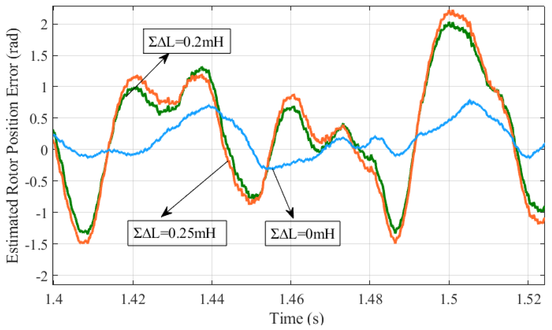
3.1.3. Current Gain Errors

The actual three-phase currents are subject to gain errors from the current sensors and sampling conditioning circuits. Those with gain errors of i a e , i b e , and i c e are expressed as
i a e i b e i c e = I e ( c o s θ + γ ) I e ( c o s θ + γ 2 / 3 π ) I e ( c o s θ + γ + 2 / 3 π )
where I e is the amplitude of the three-phase current, and the gain error γ is the difference between the injection angle and the actual angle due to the sampling accuracy and the accuracy delay.
According to the coordinate transformation equation, the actual three-phase currents are transformed into the estimated rotating coordinate system, as shown below:
i De i Qe = cos θ e s t sin θ e s t sin θ e s t cos θ e s t 2 3 1 3 1 3 0 3 3 3 3 i a e i b e i c e = I e c o s γ I e s i n γ
Substituting Equation (19) into Equation (7) gives the following:
i Q h + 2 I e s i n γ L 2 L 2 ± 2 U i L = θ
According to Equation (20), the distortion of the actual three-phase currents is added to the error coupling term containing I e and γ , which incorporates the errors into the final position information calculation.
The current errors mentioned above result in a bias between the observed rotor position and the actual rotor position. Only by implementing effective compensation strategies for position errors can the accuracy of the high-frequency pulsed signal injection method be enhanced.

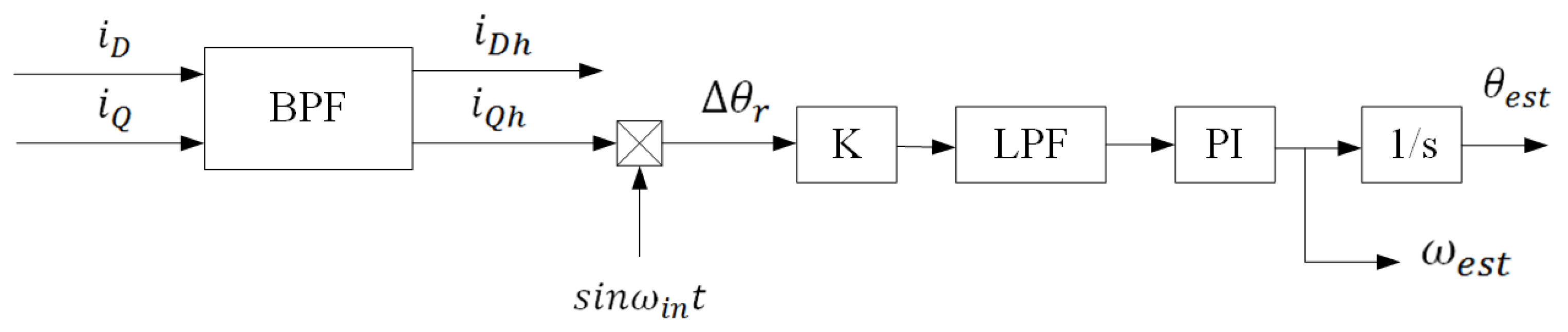
3.2. Strategy for Rotor Position Error Compensation

As demonstrated in the preceding analysis of rotor position error, utilizing conventional filters in the PMSM control system to extract the high-frequency response current introduces a phase delay angle, θ e r r . Incorporating θ e r r into the position injection method, the expression for the injection voltage in the stationary coordinate system is
u α i n j u β i n j = U i cos ω i t θ e r r 0
Equation (21) can be substituted into Equation (2):
d d t i α h i β h = 1 L 2 L 2 L + L   c o s 2 θ e s t L   s i n 2 θ e s t L   s i n 2 θ e s t L L   c o s 2 θ e s t u α i n j u β i n j
The high-frequency response current on the α β -axis of the stationary coordinate system is
i α h i β h = U i L 2 L 2 L ω i sin ω i t θ e r r L ω i sin 2 θ e s t ω i t + θ e r r L ω i cos ω i t θ e r r + L ω i sin 2 θ e s t ω i t + θ e r r
The negative estimated rotating coordinate system is defined as the stationary coordinate system rotated clockwise with the angular frequency of the high-frequency injection voltage signal. The transformation of the high-frequency response current into the negative estimated rotating coordinate system can be expressed as
i D i Q = U i L 2 L 2 L ω i sin θ e r r L ω i sin 2 θ e s t ω i t + θ e r r L ω i cos θ e r r + L ω i sin 2 θ e s t ω i t + θ e r r
The phase delay angle is derived by employing the inverse tangent function with the high-frequency response current in the negative estimated rotational coordinate system after processing using a low-pass filter.
L P F ( i D ) L P F ( i Q ) = U i L ω i ( L 2 L 2 ) sin θ e r r cos θ e r r
θ e r r = a r c t a n L P F i D L P F i Q
It is demonstrated that if the phase delay angle is compensated using the estimated rotor position angle θ e s t , which is derived from the observer, the delay effect caused by the estimated error can be eliminated, so the accuracy of rotor position estimation can be improved. A block diagram of this strategy is shown in Figure 6.

4. Simulation and Experimental Analysis

The proposed compensation strategy was verified through simulation and experiments. Firstly, a simulation model of the IPMSM sensorless control system was constructed using MATLAB/Simulink R2021b. The parameters of the motor in the simulation model are delineated in Table 1. The pulse-width modulation (PWM) carrier frequency was 5 kHz, the frequency of the sinusoidal voltage injection signal was 1 kHz, and the amplitude was 20 V. The center frequency of the second-order BPL was 1 kHz, the bandwidth was 100 Hz, and the cut-off frequency of the LPF was 60 Hz.

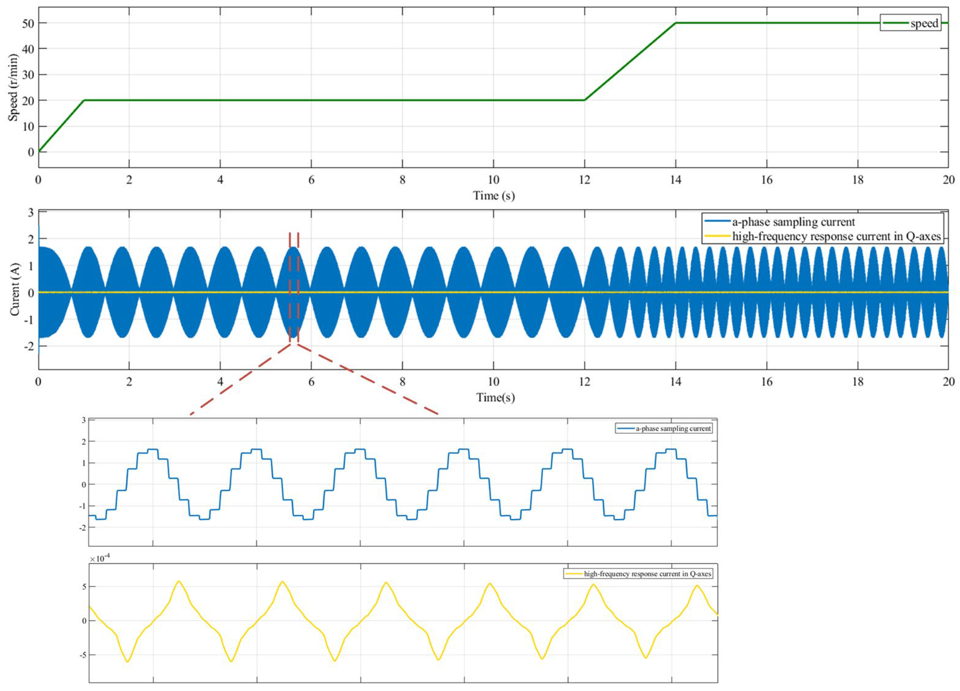
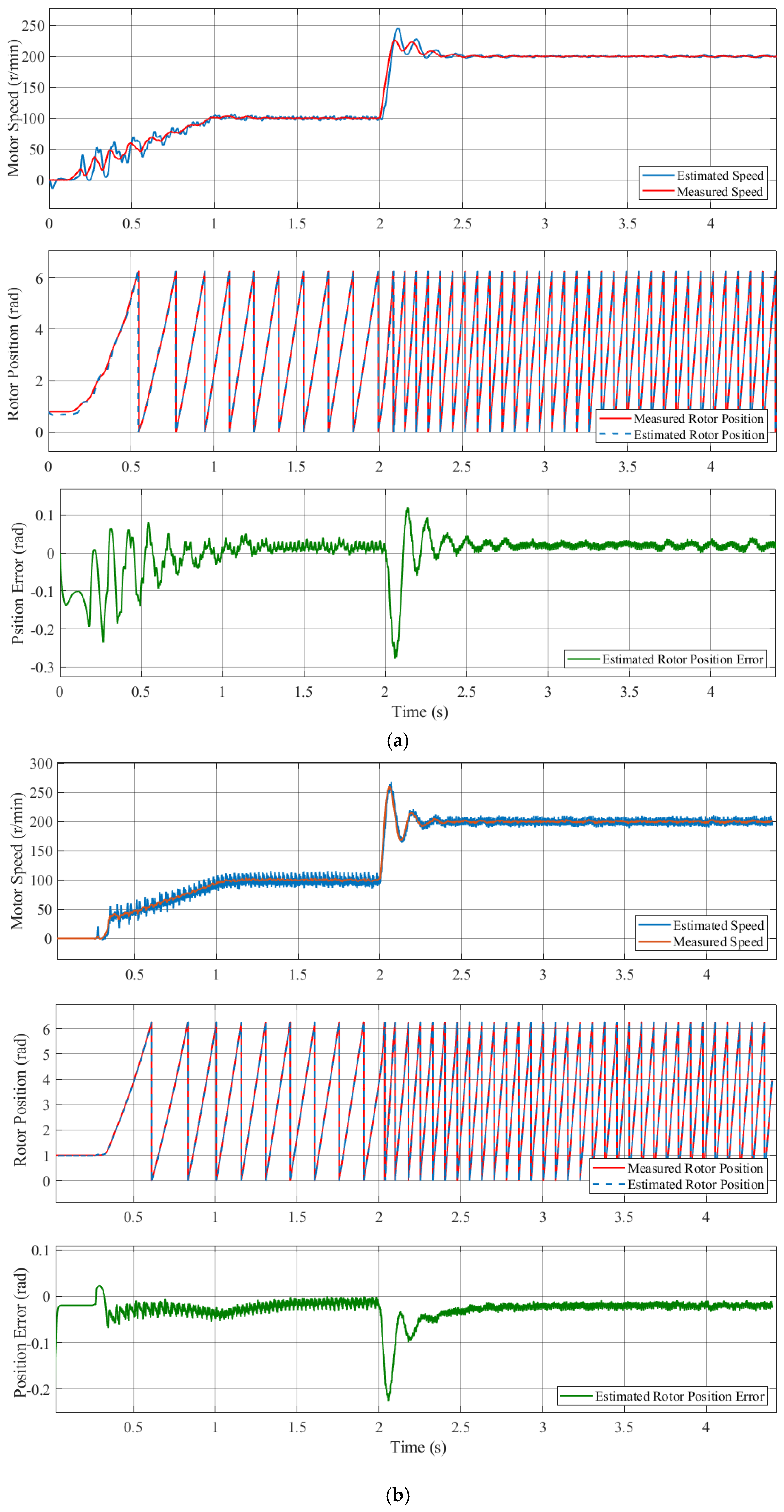
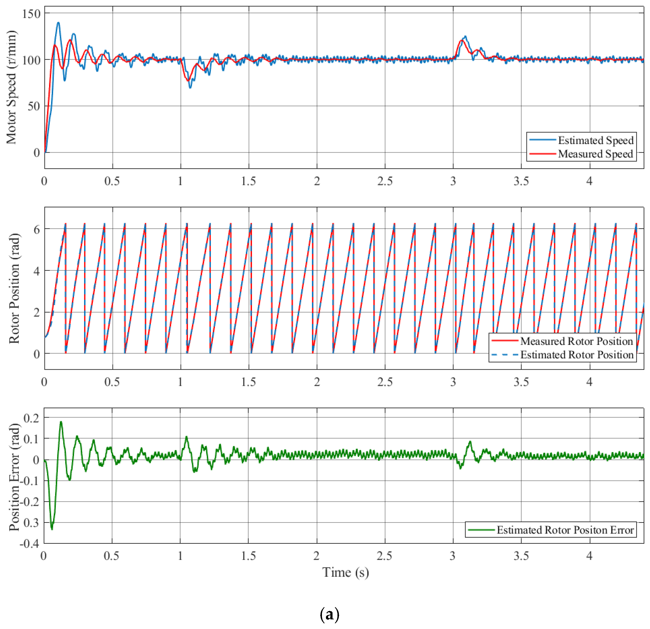
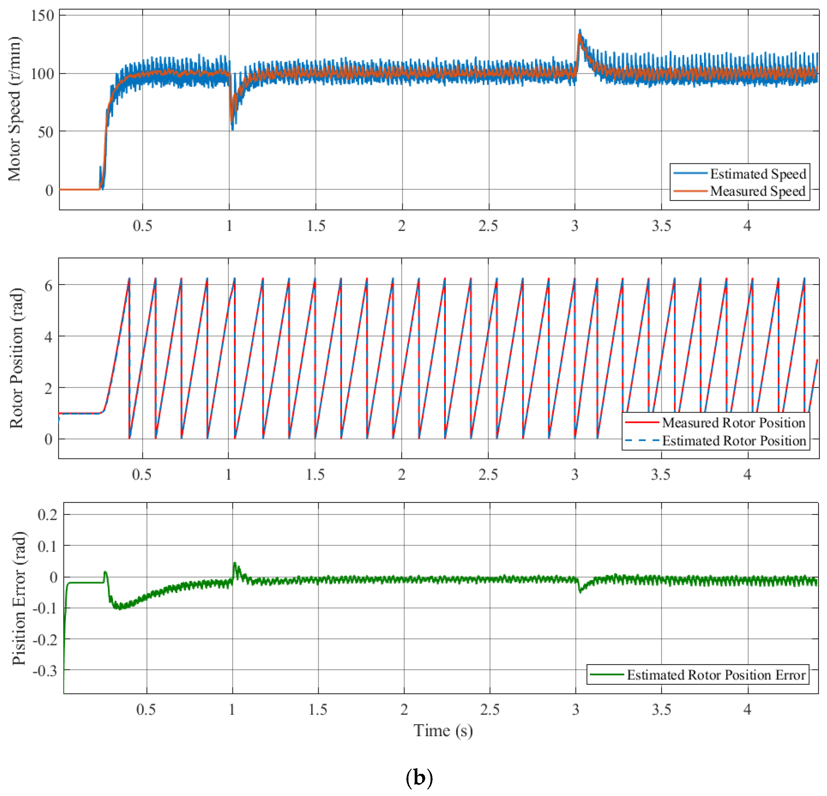
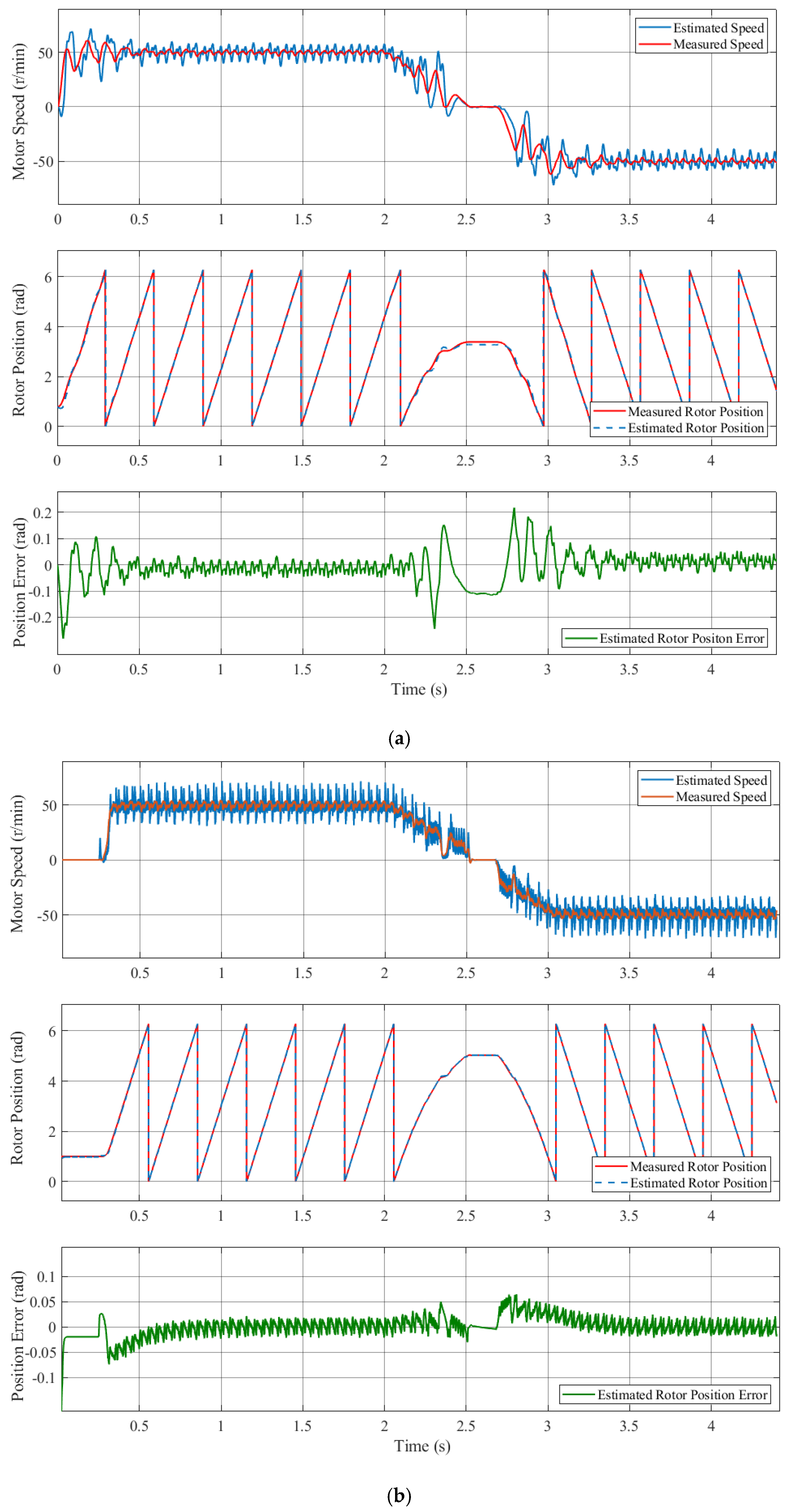
4.1. Simulation Results

Figure 7 shows the sampling three-phase current i a and the high-frequency response current i Q h , which was extracted by the BPF in the estimated rotating coordinate system when the motor ran at 0–20–50 r/min with no load. The i Q h waveform is symmetrical in the positive and negative directions, and it is consistent with the sampling three-phase current. This indicates that the high-frequency response current could be effectively separated and extracted by using the extraction method for rotor position error compensation in the block diagram.
Figure 8 shows the rotor position and estimated position error waveforms for the conventional high-frequency pulsed signal injection method and the proposed compensation strategy when the motor speed was step-increased from 0 r/min to 100 r/min to 200 r/min. The variation curve of the estimated motor speed in these figures demonstrates that the motor speed remains stable after a slight overshoot for both methods of operation. As the speed undergoes variation, the estimated error demonstrates a relatively major change, but when the speed is stable, the estimated error is small. As demonstrated in Figure 8a, the maximum estimated rotor position error in the conventional method was 0.28 rad, and the steady-state estimated rotor position error was approximately 0.03 rad. As illustrated in Figure 8b, the maximum estimated rotor position error in the conventional method was 0.22 rad, and the steady-state estimated rotor position error was approximately 0.02 rad. It can be seen that the amplitude of the estimated rotor position error signal after the compensation is smaller, which means the estimated rotor position is closer to the measured rotor position. The comparison further demonstrates that the estimated speed is smoother at the higher motor speed, which indicates the superiority of compensation. The simulation results verify that the compensation strategy can effectively eliminate the estimated rotor position error; consequently, a more precise measurement of the rotor position is obtained.
Figure 9 shows the rotor position and estimated position error waveforms for the conventional high-frequency pulsed signal injection method and the proposed compensation strategy under the load variation operation condition for a motor speed of 100 r/min, with loading of 2 Nm at 1 s and unloading at 3 s. The variation curve of the estimated motor speed in these figures demonstrates that the motor speed fluctuated during loading and unloading. As illustrated in Figure 9a, the maximum estimated rotor position error was 0.11 rad in the conventional high-frequency pulsed signal injection method, and as illustrated in Figure 9b, the maximum estimated rotor position error was 0.05 rad with the proposed compensation strategy. In contrast, the estimated position error at unloading is comparatively diminished. The motor started with a slight overshoot and then stabilized at the given speed. The estimated position and motor speed are shown to converge stably during the operation process, thus demonstrating that the proposed method exhibits satisfactory dynamic performance under the load variation operation conditions.
Figure 10 shows the rotor position and estimated position error waveforms for the conventional high-frequency pulsed signal injection method and the proposed compensation strategy under the forward and reverse rotation operation conditions. From the forward rotation to reverse rotation, the estimated speed and estimated rotor position were determined. As illustrated in Figure 10a, for the conventional method, the maximum estimated position error was 0.21 rad when passing through 0 r/min, and the average estimated position error was 0.04 rad under the forward and reverse rotation conditions. As illustrated in Figure 10b, for the proposed method, the maximum estimated position error was 0.06 rad when passing through 0 r/min, and the average estimated position error was 0.025 rad under the forward and reverse rotation conditions.
A detailed comparison of the estimated rotor position error under varied operation conditions is shown in Table 2. The simulated results verify that the compensation strategy can effectively eliminate the estimated rotor position error.

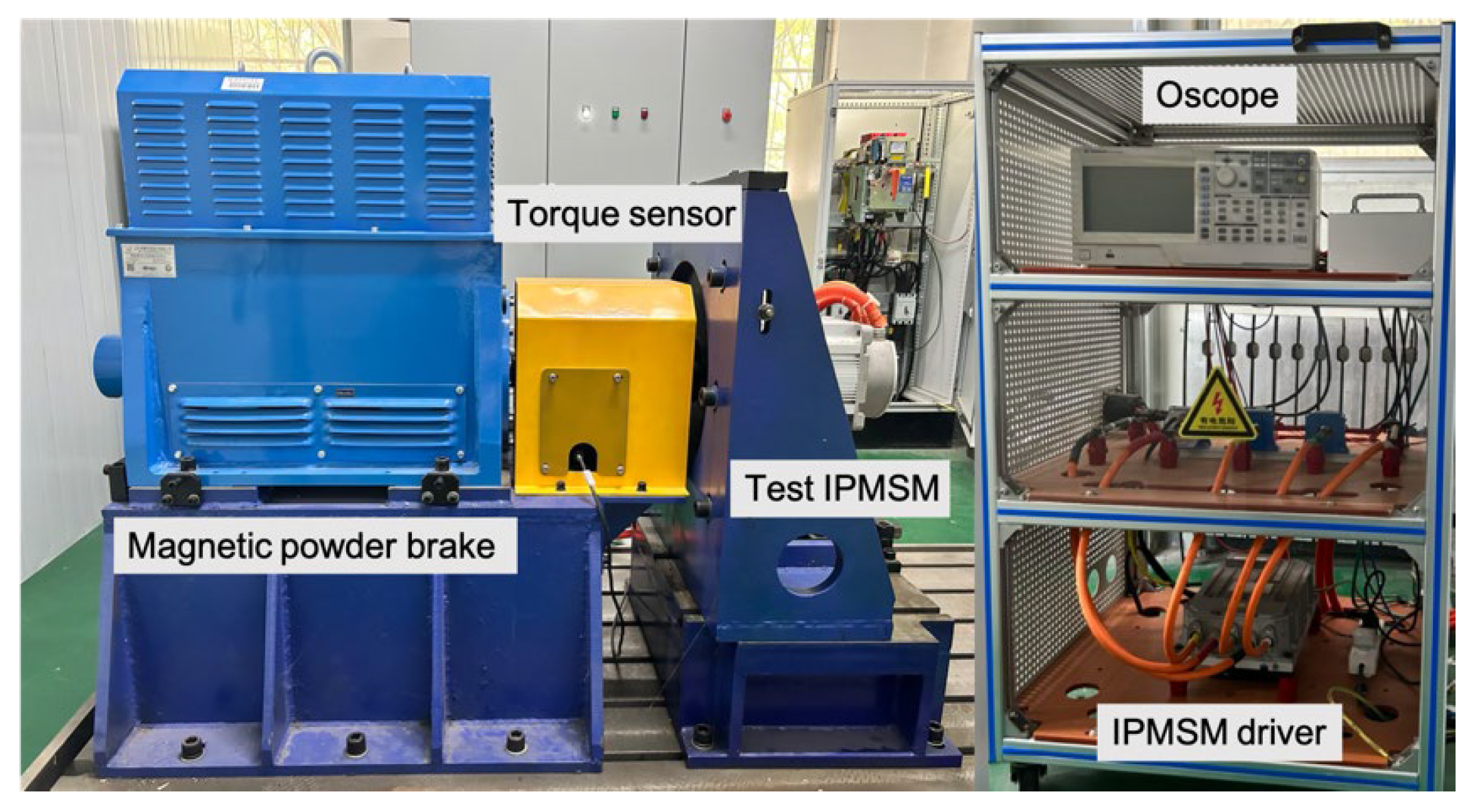
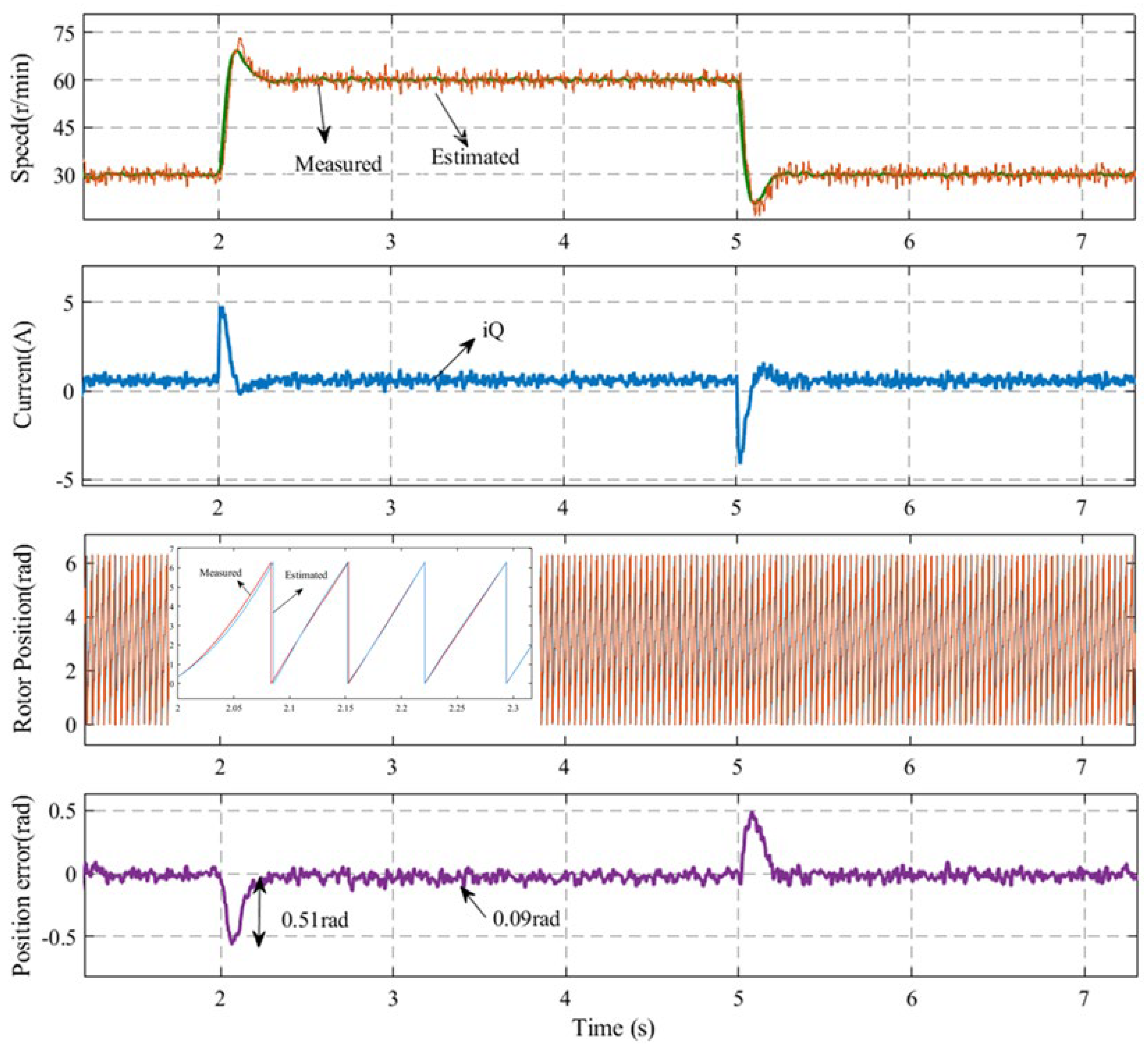
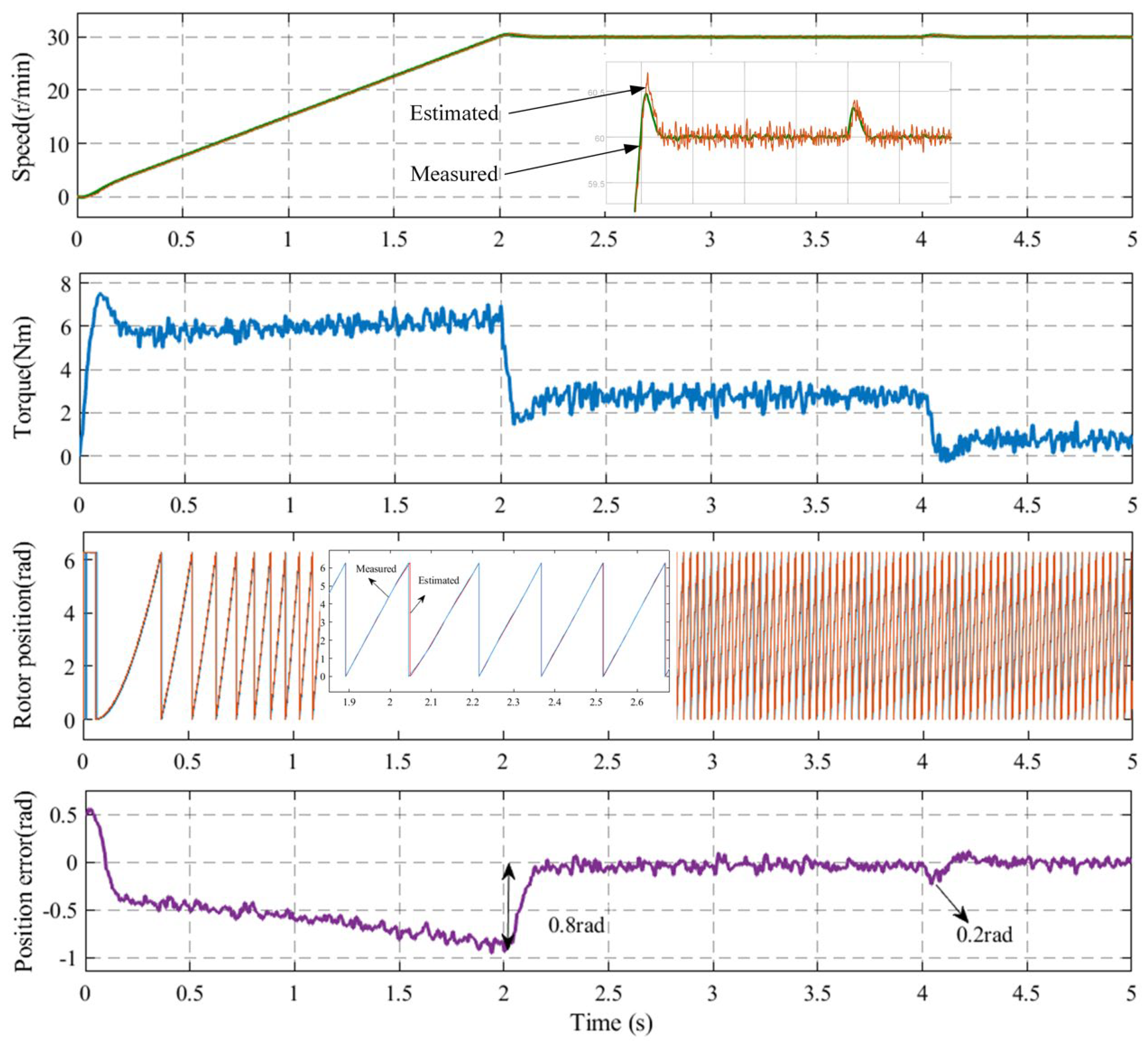
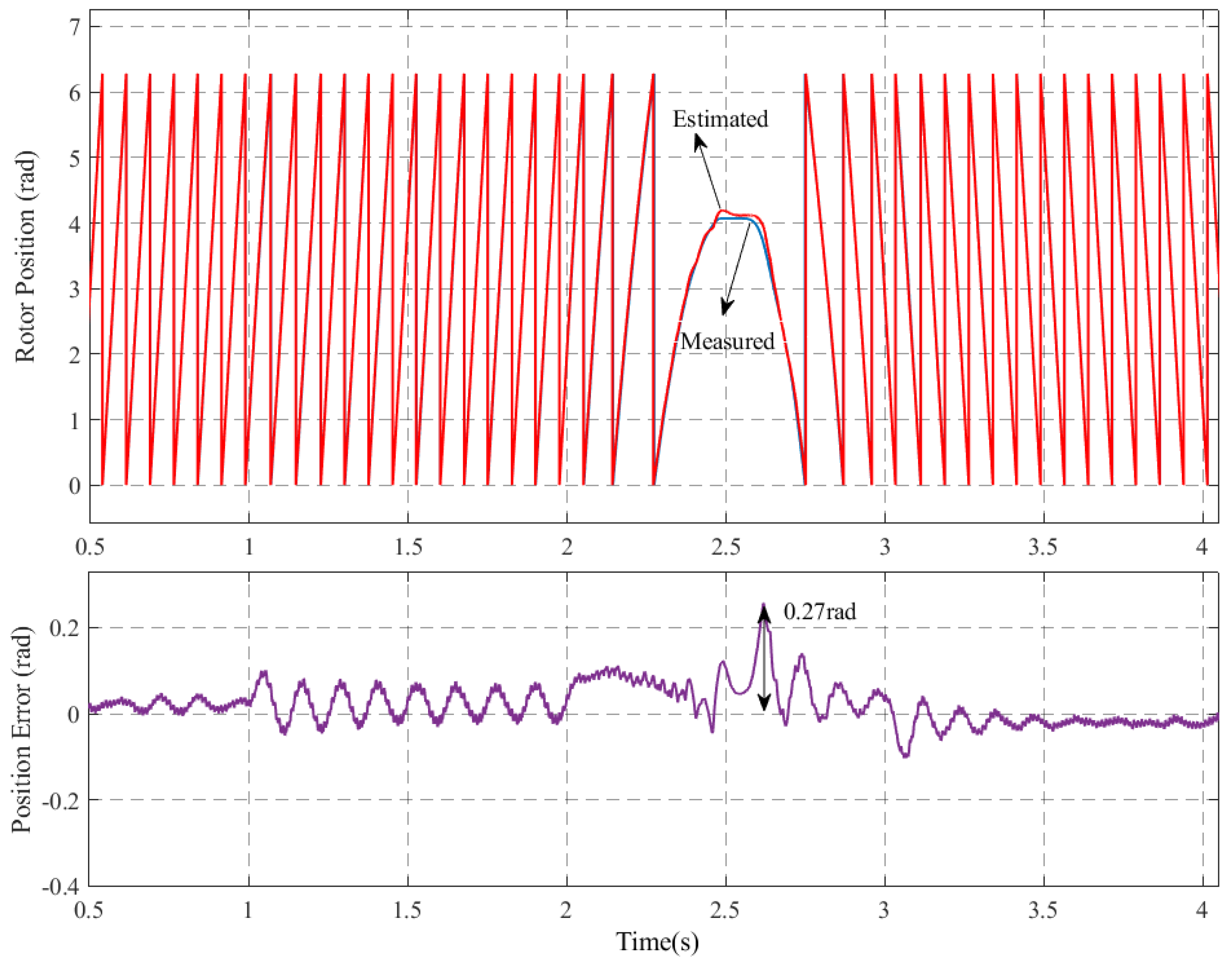
4.2. Experimental Results

The proposed sensorless control system using the error compensation strategy was verified on a platform, as shown in Figure 11. The parameters of the IPMSM selected were the same as those in the simulation analysis. The load was a hysteresis dynamometer, which could provide torque from 0 to 5 Nm. The system used a photoelectric encoder to detect the actual rotor position, which was used in a comparison with the observed value of the position information. The PWM carrier frequency was 10 kHz, the current sampling frequency was 10 kHz, the frequency of the injection voltage signal was 1 kHz, and the amplitude was 20 V.
Figure 12 shows the controlled performance of the IPMSM at varied speeds of 30–60–30 r/min using the compensation strategy. The waveforms include the motor speed, current, estimated rotor position, and error comparing the sensor and the sensorless control systems. It is evident that the operation of the motor was relatively smooth. When the rotational speed changed, the instantaneous estimated rotor position error was approximately 0.51 rad, and when the rotational speed was stable, the average steady-state estimated rotor position error was about 0.09 rad. The experimental results demonstrate that the IPMSM exhibited satisfactory dynamic performance when utilizing the compensation strategy proposed in this paper under conditions of speed variation.
Figure 13 shows the controlled performance of the IPMSM when starting with a 5 Nm load and progressing to speed at 60 r/min with sudden unloading. The waveforms include the motor speed, torque, estimated rotor position, and error comparing the sensor and the sensorless control systems. As demonstrated in the figure, the IPMSM exhibited an initial overshooting tendency following startup, and it was subsequently stable at the designated speed. The motor speed fluctuated when the load was abruptly released, with the maximum instantaneous estimated rotor position error reaching approximately 0.8 rad. However, this error ultimately converged, and the average estimated rotor position error was approximately 0.2 rad. The experimental results demonstrate that the estimated rotor position angle and motor speed were maintained at a constant level during load change operation, thereby illustrating the efficacy of the proposed method in this paper.
Figure 14 shows the waveforms of the rotational speed and estimated rotor position when the motor speed changed from 30 r/min to −30 r/min, comparing the sensor and the sensorless control systems. When the motor rotated from forward to reverse, the maximum estimated position error was 0.27 rad. It is demonstrated that the estimated rotor position angle exhibited a high degree of correlation with the actual angle when crossing the zero-speed point. Furthermore, the motor speed demonstrated a capacity to rapidly track the actual motor speed. The process facilitated the seamless execution of the switching operation between forward and reverse rotating conditions.

5. Conclusions

In this paper, we investigate a sensorless control system for a PMSM operating at low speed. We analyze the causes of the rotor position error in the traditional high-frequency pulsed signal injection method and design a compensation strategy to eliminate the estimated error due to current harmonics and current gains, so as to improve the accuracy of rotor position observation. Firstly, the high-frequency signal is injected into the estimated rotating coordinate system, in which the positive- and negative-phase high-frequency currents have the same frequency, thus making the demodulation delay have the same magnitude as the phase influence. Secondly, through the phase correlation information of the negative-phase high-frequency currents, it realizes the automatic compensation of the control delay and the demodulation delay, so as to improve the positional demodulation accuracy of the rotating high-frequency injection method. The experimental results demonstrate that the method exhibited optimal performance in stable working conditions at low speed and in dynamic working conditions with an increase in speed or load. In stable working conditions, the steady-state rotor position error was maintained at 0.08 rad. Furthermore, the system exhibited operational smoothness when confronted with variations in motor speed or load. The proposed strategy for rotor position error compensation in the PMSM sensorless control system is thus shown to enhance the observation accuracy and anti-disturbance performance of the high-frequency pulsation signal injection method. It supports the operation of the PMSM at low speeds.
In subsequent research, we will focus on online identification and compensation methods for the non-linear effects of the cross-saturation effect and temperature variation on the motor parameters. Focusing on algorithm enhancement, multi-parameter non-linear modeling, and dynamic environmental noise suppression research, we will achieve motor parameter identification in complex scenarios to further improve the control accuracy of the PMSM.
Furthermore, the enhancement of the control accuracy of a PMSM at low speed facilitates the output of torque in a more fluid manner, as well as ensuring precise execution at minimal displacement, thereby contributing to the reliability of systems. This advancement has the potential to enhance the technical advantages and practical application value of PMSMs in intelligent control applications, including electric vehicles and robotics. This expansion will result in more precise and safer applications.

Author Contributions

Conceptualization, Z.L.; methodology, Z.L.; software, Z.L.; validation, Z.L.; formal analysis, Z.L.; investigation, Z.L.; resources, Z.L.; data curation, Z.L. and Y.W.; writing—original draft preparation, Z.L.; writing—review and editing, M.N.I.; visualization, Z.L.; supervision, M.N.I.; project administration, M.N.I.; funding acquisition, Y.W. All authors have read and agreed to the published version of the manuscript.

Funding

This research was funded by Key Research Projects of High Education Institutions in Henan Province at 2024 (No. 24B460014, Henan, China).

Data Availability Statement

The original contributions presented in this study are included in the article. Further inquiries can be directed to the corresponding author.

Conflicts of Interest

Author Wang Yongwei was employed by the International Joint Laboratory of Composite Tools and Precision Machining. The funder provided equipment support for data collection in the study.

References

  1. Xu, D.; Wang, B.; Zhang, G.; Wang, G.; Yu, Y. A Review of Sensorless Control Methods for AC Motor Drives. CES Trans. Electr. Mach. Syst. 2018, 2, 104–115. [Google Scholar] [CrossRef]
  2. Hua, W.; Zhu, X. Magnetic Flux Reversal Permanent Magnet Motor and Its Key Technologies Review. Proc. CSEE 2020, 40, 2657–2669. [Google Scholar]
  3. Li, C.; Wang, X. Overview of Sensorless Control Strategies for Permanent Magnet Synchronous Motors. Electr. Drive Autom. 2024, 46, 11–16. [Google Scholar]
  4. Wang, G.; Valla, M.; Solsona, J. Position Sensorless Permanent Magnet Synchronous Machine Drives—A Review. IEEE Trans. Ind. Electron. 2019, 67, 5830–5842. [Google Scholar] [CrossRef]
  5. Lu, J.; Liu, J. Low-Speed Sensorless Control for Interior Permanent Magnet Synchronous Motors. Electr. Mach. Control 2018, 22, 88. [Google Scholar]
  6. Zhang, Z.; Shen, A.; Li, P.; Luo, X.; Tang, Q. MTPA-Based High-Frequency Square Wave Voltage Signal Injection Strategy for IPMSM Control. J. Power Electron. 2021, 21, 1461. [Google Scholar] [CrossRef]
  7. Wang, G.; Yang, L.; Zhang, G.; Zhang, X.; Xu, D. Comparative Investigation of Pseudorandom High-Frequency Signal Injection Schemes for Sensorless IPMSM Drives. IEEE Trans. Power Electron. 2016, 32, 2123–2132. [Google Scholar] [CrossRef]
  8. Sheng, L.; Liu, L.; Ye, Y. Current Status and Prospects of Sensorless Control for Permanent Magnet Synchronous Motors. Electrotech. Electr. 2023, 2, 1–8. [Google Scholar]
  9. Li, X.; Du, J.; Liang, D.; Huang, F.; Lou, J. Low-Speed Sensorless Control for Permanent Magnet Linear Motors Based on Improved Pulsating Injection Method. Electr. Mach. Control 2018, 22, 31. [Google Scholar]
  10. Li, W.; Liu, J. Sensorless Optimization Method for Interior Permanent Magnet Synchronous Motors Considering Magnetic Saturation and Cross-Coupling Effects. Electr. Mach. Control 2020, 35, 4465. [Google Scholar]
  11. Peng, S.Q.; Jiang, Y.H.; Lan, Z.Y.; Li, F. Novel Exponential Adaptive Sliding Mode Observer for Sensorless Control of Permanent Magnet Synchronous Motors. Electr. Mach. Control 2022, 26, 104. [Google Scholar]
  12. Lu, W.; Zhang, Z.; Wang, D.; Lu, K.; Wu, D.; Ji, K.; Guo, L. A New Load Torque Identification Sliding Mode Observer for Permanent Magnet Synchronous Machine Drive System. IEEE Trans. Power Electron. 2019, 34, 7852. [Google Scholar] [CrossRef]
  13. Wang, C.; Gou, L.; Zhou, M.; You, X.; Dong, S. Sensorless Control for Interior Permanent Magnet Synchronous Motors Based on Improved Discrete Second-Order Sliding Mode Observer. Electr. Mach. Control 2023, 38, 387. [Google Scholar]
  14. Lin, M.; Li, Y.H.; Wu, C.; Yuan, G.Q.; Li, C. Predictive Control of Permanent Magnet Synchronous Motors Based on Sliding Mode Model Reference Adaptive System Observer. Electr. Mach. Control 2017, 32, 156. [Google Scholar]
  15. Zhang, Y.; Xu, B.; Wei, H.; Li, H.; Liu, W. Novel Model Reference Adaptive Deadbeat Current Predictive Control for PMSM. Electr. Mach. Control 2023, 27, 157. [Google Scholar]
  16. Li, Z.; An, J.; Xiao, Y.; Zhang, Q.; Sun, H. Design of Model Predictive Control System for Permanent Magnet Linear Motors Based on Adaptive Observer. Electr. Mach. Control 2021, 36, 1190. [Google Scholar]
  17. Quang, N.K.; Hieu, N.T.; Ha, Q.P. FPGA-Based Sensorless PMSM Speed Control Using Reduced-Order Extended Kalman Filters. IEEE Trans. Ind. Electron. 2014, 61, 65. [Google Scholar] [CrossRef]
  18. Li, H.; Xu, H.; Xu, Y. Model Predictive Torque Control of Permanent Magnet Synchronous Motor Under Extended Kalman Filter Parameter Identification. Electr. Mach. Control 2023, 27, 19. [Google Scholar]
  19. Dong, S.; Zhou, M.; You, X.; Wang, C. A Sensorless Control Strategy of Injecting HF Voltage into D-Axis for IPMSM in Full Speed Range. IEEE Trans. Power Electron. 2022, 37, 13587. [Google Scholar] [CrossRef]
  20. Liu, H.; Zhou, B.; Guo, H.; Liu, B.; Li, J.; Xu, X.; Shi, R. Error Analysis of Pulsating High-Frequency Signal Injection Method. Electr. Mach. Control 2015, 30, 38–44. [Google Scholar]
  21. Wang, S.; Yang, K.; Chen, K. An Improved Position-Sensorless Control Method at Low Speed for PMSM Based on High-Frequency Signal Injection into a Rotating Reference Frame. IEEE Access 2019, 7, 86510–86521. [Google Scholar] [CrossRef]
  22. Wang, X.; Fang, X.; Wang, Z.; Zhong, Z.; Wang, Y.; Lin, F.; Yang, Z. Self-Adjusting Strategy Based on Rotating Injection for Sensorless Control of High-Power PMSM Drives. In Proceedings of the 10th International Conference on Power Electronics, Busan, Republic of Korea, 27–30 May 2019; pp. 718–723. [Google Scholar]
  23. Szabo, G.; Veszpremi, K. Sensorless Vector Control of Permanent Magnet Synchronous Machine Using High-Frequency Rotating Injection. In Proceedings of the IEEE 19th International Power Electronics and Motion Control Conference, Gliwice, Poland, 25–29 April 2021; pp. 588–593. [Google Scholar]
  24. Zhang, G.; Wang, G.; Xu, D. Initial Position Detection Method for Permanent Magnet Synchronous Motors Based on Filterless Square-Wave Signal Injection. Electr. Mach. Control 2017, 32, 165. [Google Scholar]
  25. Wang, Z.; Gao, C.; Gu, M.; Cheng, M. A Novel Vector Magnetic Circuit Based Position Observer for IPMSM Drives Using High-Frequency Signal Injection. IEEE Trans. Power Electron. 2023, 39, 1333–1342. [Google Scholar] [CrossRef]
  26. Lü, X.; Liu, G.; Mao, K. Initial Position Detection of Permanent Magnet Motors Based on Virtual Pulsating High-Frequency Injection Method. Electr. Mach. Control 2017, 32, 34–41. [Google Scholar]
  27. Liu, J.M.; Zhu, Z.Q. Novel Sensorless Control Strategy with Injection of High-Frequency Pulsating Carrier Signal into Stationary Reference Frame. IEEE Trans. Ind. Appl. 2013, 50, 2574–2583. [Google Scholar] [CrossRef]
  28. Luo, X.; Tang, Q.; Shen, A.; Zhang, Q. PMSM Sensorless Control by Injecting HF Pulsating Carrier Signal into Estimated Fixed-Frequency Rotating Reference Frame. IEEE Trans. Ind. Electron. 2016, 63, 2294–2303. [Google Scholar] [CrossRef]
  29. Zhou, Q.; Wang, Y.; Shi, K.; Zhang, Y.; Du, G. High-Frequency Pulsating Voltage Injection Based on Generalized Second-Order Integrator for PMSM Sensorless Control. Electr. Mach. Control. 2024, 28, 179–188. [Google Scholar]
  30. Wang, J.; Yan, J.; Ji, G.; Shan, L.; Ying, Z. A Dual Position Observer-Based Sensorless Control Method for Permanent Magnet Synchronous Motors at Low Speeds. Trans. China Electrotech. Soc. 2023, 38, 375–386. [Google Scholar]
  31. Dong, W.; Zhu, X.; Zhang, L.; Xu, L.; Peng, Z.; Chen, W. Research on Sensorless Control of Leakage-Flux Controllable Permanent Magnet Motors Based on Adaptive Demodulation Robust Observer. Proc. CSEE 2023, 43, 6840–6852. [Google Scholar]
  32. Liu, J.; Fu, K.; Mai, Z.; Xiao, F.; Zhang, W. Sensorless Control Strategy of Improved HF Pulsating Voltage Injection Based on Dual Frequency Notch Filter. Proc. CSEE 2021, 41, 749. [Google Scholar]
  33. Li, H.; Zhang, X.; Yang, S.; Li, F.; Ma, M. Improved Initial Rotor Position Estimation of IPMSM Using Amplitude Demodulation Method Based on HF Carrier Signal Injection. In Proceedings of the 43rd Annual Conference of the IEEE Industrial Electronics Society, Beijing, China, 29 October–1 November 2017; pp. 1996–2001. [Google Scholar]
  34. Yang, S.C.; Yang, S.; Hu, J. Design Consideration on the Square-Wave Voltage Injection for Sensorless Drive of Interior Permanent-Magnet Machines. IEEE Trans. Ind. Electron. 2017, 64, 159. [Google Scholar] [CrossRef]
  35. Li, D.; Yuan, J.; Wang, K. SOGI Cascaded SFNF-Based High-Frequency Injection Sensorless Motor Control Method. Electr. Mach. Control 2024, 28, 24–32. [Google Scholar]
  36. Hinkkanen, M.; Pescetto, P.; Molsa, E.; Saarakkala, S.E.; Pellegrino, G.; Bojoi, R. Sensorless Self-Commissioning of Synchronous Reluctance Motors at Standstill Without Rotor Locking. IEEE Trans. Ind. Appl. 2017, 53, 2120–2129. [Google Scholar] [CrossRef]
  37. Wang, G.; Qu, L.; Zhan, H.; Xu, J.; Ding, L.; Zhang, G.; Xu, D. Self-Commissioning of Permanent Magnet Synchronous Machine Drives at Standstill Considering Inverter Nonlinearities. IEEE Trans. Power Electron. 2014, 29, 6615–6627. [Google Scholar] [CrossRef]
  38. Zhang, G.; Wang, G.; Xu, D.; Fu, Y.; Ni, R. Rotor Position Observation Method for Interior Permanent Magnet Motors Based on Adaptive Notch Filter. Proc. CSEE 2016, 36, 2521–2527. [Google Scholar]
  39. Nian, H.; Li, J.; Wan, Z. Sensorless Control Technology for Permanent Magnet Wind Generators Based on Online Parameter Identification. Proc. CSEE 2012, 32, 146–154. [Google Scholar]
  40. Huang, K.; Gao, L.; Huang, S. Rotor Position Correction Method for High-Speed Permanent Magnet Synchronous Motors Based on Current Loop Error Compensation. Proc. CSEE 2017, 37, 241–249. [Google Scholar]
  41. Shi, X.; Wang, X.; Xu, T.; Gu, C. Self-Optimizing Commutation Correction Strategy for High-Speed Brushless DC Motors. Electr. Mach. Control 2019, 34, 3997–4005. [Google Scholar]
  42. Gu, C.; Wang, X.; Zhang, F.; Deng, Z. Correction of Rotor Position Estimation Error for High-Speed Permanent Magnet Synchronous Motor Sensorless Drive System Based on Minimum-Current-Tracking Method. IEEE Trans. Ind. Electron. 2020, 67, 8271–8280. [Google Scholar] [CrossRef]
Figure 1. Block diagram of the high-frequency pulsed signal injection method of PMSM sensorless control system.
Wevj 16 00261 g001
Figure 2. Definitions of the angles and coordinate systems.
Wevj 16 00261 g002
Figure 3. Block diagram of the position observer based on PLL.
Wevj 16 00261 g003
Figure 4. Phase–frequency curve of the second-order BPF.
Wevj 16 00261 g004
Figure 5. Estimated rotor position error is influenced by the difference self-inductance.
Wevj 16 00261 g005
Figure 6. A block diagram of the strategy for rotor position error compensation.
Wevj 16 00261 g006
Figure 7. Simulation results of the sampling three-phase current i a and the high-frequency response current i Q h at 0–20–50 r/min.
Wevj 16 00261 g007
Figure 8. Simulated results of the motor under the speed variation operation condition 0 r/min–100 r/min–200 r/min. (a) The conventional high-frequency pulsed signal injection method; (b) the proposed compensation strategy.
Wevj 16 00261 g008
Figure 9. Simulated results of the motor under the load variation operation condition: load 2 Nm between 1 s and 3 s. (a) The conventional high-frequency pulsed signal injection method; (b) the proposed compensation strategy.
Wevj 16 00261 g009aWevj 16 00261 g009b
Figure 10. Simulated results of the motor under the forward and reverse rotation operation conditions: from 50 r/min to −50 r/min. (a) The conventional high-frequency pulsed signal injection method; (b) the proposed compensation strategy.
Wevj 16 00261 g010
Figure 11. Experimental platform of IPMSM drive.
Wevj 16 00261 g011
Figure 12. Controlled performance of the IPMSM at varied speeds of 30–60–30 r/min operation for the compensation strategy.
Wevj 16 00261 g012
Figure 13. Controlled performance of the IPMSM at varied load operations for the compensation strategy.
Wevj 16 00261 g013
Figure 14. Controlled performance of the IPMSM on the switching operation for the compensation strategy.
Wevj 16 00261 g014
Table 1. The parameters of IPMSM.
ParameterValueUnit
Rotor poles2
Rated voltage380V
Rated speed1500r/min
Rated power1.18kW
Rated torque7.5Nm
Phase resistance0.91Rs/Ω
d-axis inductance3.96mH
q-axis inductance7.96mH
Flux linkage0.1827Wb
Table 2. Comparison of the estimated rotor position error for the conventional method and the proposed strategy.
Operation ConditionsConventional MethodProposed Strategy
Speed variation0.28 rad0.22 rad
Load variation0.11 rad0.05 rad
Forward and reverse rotation0.21 rad0.06 rad
Disclaimer/Publisher’s Note: The statements, opinions and data contained in all publications are solely those of the individual author(s) and contributor(s) and not of MDPI and/or the editor(s). MDPI and/or the editor(s) disclaim responsibility for any injury to people or property resulting from any ideas, methods, instructions or products referred to in the content.

