Abstract
Since vehicle attitude cannot be readily measured, this paper designs a state observer based on the information available on the CAN bus. The attitude angle estimated in this way is not only robust in practical applications but can also replace an IMU sensor for accurate remaining fuel range prediction under complex driving conditions. The primary innovation of this work is the development of an extended Kalman filter (EKF)-based estimation of the vehicle pitch attitude angle and its deployment in real-world vehicle systems. Firstly, a vehicle longitudinal model considering the suspension dynamics is established, followed by a model-based extended Kalman filter (EKF) design. Then, the EKF algorithm is verified by a co-simulation using Simulink and CarSim of typical working conditions. Numerical tests indicate the effectiveness of the EKF algorithm, with the estimation error being below 0.5°. Finally, the proposed EKF is engineered to range-extended NETA electrical vehicles and applied for reliable remaining fuel range prediction. The mass-production application proves that the EKF observer can respond to changes in body pitch motion stably and rapidly, and the estimated error is less than 1.5°.
1. Introduction
Over the past few decades, the automotive industry has been undergoing rapid developments, shaping three principal trends centered on electrification, networking, and intelligence. Meanwhile, there has been increasing concern for energy saving and environment protection, which are now highly valued by the public. Thus, the research and development of next-generation new energy vehicles and the completion of the electrification transformation have been set as strategic priorities for many automakers. It has been widely accepted that plug-in range-extended electric vehicles (REEVs) are a promising option in the transition from conventional fuel-powered vehicles to all-electric ones. The range anxiety associated with pure electric vehicles is effectively addressed by incorporating an auxiliary power unit (APU). However, this also introduces a challenge of accurately estimating the vehicle’s remaining fuel range. Like traditional internal combustion engine (ICE) vehicles, REEVs tackle this by tracking the fuel level in the tank. Yet, the fuel gauge can become significantly inaccurate due to the dynamic pitch motion. In order be able to achieve an accurate estimation, more advanced sensors such as inertial measurement units (IMUs) are often integrated to capture comprehensive data. This indeed improves the performance, but it also adds to production costs, which are now being very carefully and dedicatedly managed. Therefore, the use of high-precision virtual sensors to estimate the necessary vehicle states will have high practical value, which is the topic of this paper.
At present, the main method of vehicle state (and parameter) estimation is to design a model-based state observer depending on signals (e.g., vehicle speed, acceleration, and etc.) available from a controller area network (CAN) bus, and to integrate this with the kinematics and/or dynamics of the entire vehicle [1,2]. Commonly used design methods include sliding mode observers (SMOs) [3], Luenberger observers (LOBs) [4,5], the recursive least squares (RLS) approach [6,7,8], and Kalman filters (KLFs) [9,10,11,12,13,14]. Among them, Kalman filters, in addition to their improved variations, have attracted interest for their notable estimation performance in terms of accuracy and stability. For instance, a theoretical framework for dual Kalman filters is developed in [9] for observing vehicle states jointly. The first KLF estimates the parameters like the vehicle side-slip angle, rolling attitude, and tire lateral force, while the road adhesion coefficient is predicated and iteratively updated using the square root of the error covariance matrix in the second KLF. In [10], a road grade is estimated by a KLF based on the vehicle’s longitudinal dynamics and kinematics, and its effectiveness is validated through TruckSim and Simulink co-simulation. An algorithm for a decaying-memory unscented Kalman filter (UKF) is proposed in [11] for four-wheel independent-drive vehicles, which employs optimal estimation theory to jointly observe the longitudinal acceleration and road gradient. An overall estimation of road gradient and vehicle mass based on the longitudinal dynamic model is conducted in [12]. Moreover, in [13] a Kalman filter integrated with a fuzzy system for road slope estimation is proposed, which improves the accuracy and robustness by appropriately tuning the acceleration sensor. Nevertheless, this method requires an additional gyroscope, which adds to the cost and complexity of the algorithm. An extended Kalman filter (EKF) is implemented in [14,15], integrating with the vehicle longitudinal dynamics model to estimate the vehicle mass and the road gradient comprehensively.
The estimation of the road slope by the above-mentioned KLF algorithm is often used by car companies to replace high-cost IMU sensors to realize the monitoring of the vehicle attitude angle, so as to achieve the purpose of reducing costs and increasing efficiency. However, this method of estimating the vehicle attitude has difficulties when applied to an extended-range EV, which is the case for this paper. This is due to the fact that a range-extended vehicle has greater responsive propelling torque and even greater inertia (partly contributed by the high-voltage battery). Especially when there is a sudden acceleration (and/or deceleration), the vehicle is more prone to leaning backward (and/or forward). As a result, the pitch motion becomes significant even on a slope road, which affects the estimation accuracy of the fuel level and thus the remaining fuel range. Therefore, it is important to investigate estimations of the vehicle attitude angle of REEVs, realizing an accurate, stable, and low-cost virtual sensor of the vehicle body states, and improving the accuracy of remaining fuel range predictions.
For the aforementioned challenges for REEVs, this paper presents a novel vehicle attitude estimation approach, which utilizes the existing longitudinal speed and acceleration signals from the CAN bus. The approach can achieve sufficient accuracy for remaining fuel range estimation even in complex environments and extreme driving conditions such as emergency accelerations and decelerations on slops. The paper is organized as follows. Initially, a vehicle longitudinal model is established, incorporating comprehensive suspension dynamics. Next, an extended Kalman filter (EKF) algorithm is developed for vehicle attitude angle estimation, which is based on the discrete state-space equation of an REEV. Then, a hybrid simulation approach, which uses CarSim and Simulink, is adopted to rigorously validate the proposed virtual attitude angle sensor. Finally, the virtual sensor is engineered and implemented in mass-production Neta S vehicles. The effectiveness of the algorithm is assessed through real-world vehicle application. Both the numerical simulations and real-vehicle road and field tests confirm that the proposed method satisfies the stringent requirements for remaining fuel range estimation.
The main contributions of this paper are as follows:
- The proposed method demonstrates robust and practical estimation of the vehicle pitch attitude angle.
- The estimation approach has the potential to replace IMU sensors for accurate fuel range prediction in complex driving conditions.
- The application of the EKF algorithm in mass-production vehicles, specifically in NETA electric vehicles, proves its effectiveness in reliably predicting fuel range and accurately estimating body pitch angles.
2. Model-Based Vehicle Pitch Attitude Estimation
2.1. Vehicle Longitudinal Dynamics and Suspension Model
The following assumptions are made for the vehicle longitudinal and suspension dynamics modeling:
- Tire stiffness is much higher than that of the suspension. Thus, its impact on the vehicle pitch angle estimation is minimal.
- The vehicle mass and center of mass are assumed to be constant throughout the EKF development and deployment.
- Suspension stiffness and damping are assumed to be constant, ignoring variations due to wear or environmental factors.
- Road and environmental excitations are assumed to follow a Gaussian distribution, simplifying the modeling of random disturbances.
The vehicle pitch attitude of REEVs is often measured using an IMU that is mounted on the body. This measured attitude angle mainly consists of two parts: one is caused by the road gradient and the other is due to the vehicle weight transformer , as shown in Figure 1. Thus, the vehicle attitude angle can be represented as
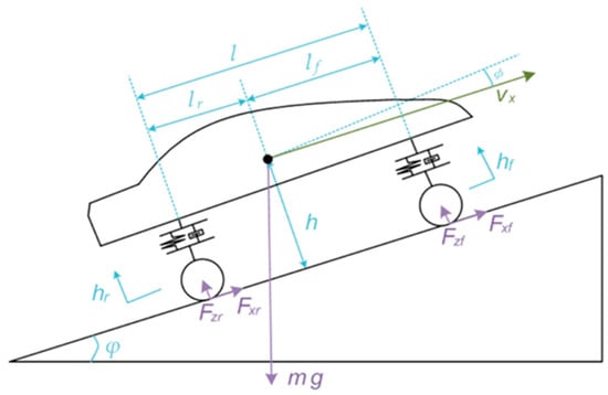
Figure 1.
Vehicle pitch attitude.
The estimation of requires a measurement of the longitudinal acceleration and knowledge of the longitudinal kinematics and dynamics. For a detailed explanation of these and other symbols, please refer to Table A1 in Appendix A. The longitudinal kinematics are given by
where represents the longitudinal acceleration; the longitudinal speed; and the gravitational acceleration. The longitudinal dynamic model of the vehicle is as below:
where is the mass of the vehicle; the rolling resistance coefficient; the air density; the air-drag coefficient; and the frontal area of the vehicle. The second term on the right-hand side of the above equation represents the air-drag force , which grows nonlinearly along with the vehicle speed. The third term is the rolling resistance , which depends on the relative rotating speed of tire with respect to the ground. is taken to be a constant in this paper. Referring to Equation (2), please note the gravitational resistance is inside the term of . The dynamics associated with the suspension system are simplified using the equivalent stiffness and damping, as shown in Figure 1. Based on the characteristics of the vehicle pitch motion, the weight-transfer-induced pitch angle can be expressed as
where and are the equivalent damping coefficients of the front and rear suspensions, respectively; and the corresponding equivalent stiffnesses; and the respective vertical loads on the front and rear axles; and the distances of the front and rear axle to the mass center; is the wheelbase; and , represents the lumped pitch damping and stiffness of the suspension system.
The force balance analysis shown in Figure 1 yields the vertical load and as below:
where is the height of center of mass.
It can be observed that and are composed of two parts, namely the static and dynamic loads. The static load can be determined by the vehicle kinetics solely, while the dynamic load is associated with the weight transfer due to the vehicle acceleration (and/or deceleration). When the vehicle accelerates (or decelerates) rapidly, the deviation between and grows. This is due to the vehicle pitch backward (or forward) motion. Substituting Equations (2) and (4) into Equation (3) results in
2.2. Extended Kalman Filter Algorithm
As shown in Figure 2, a simplified diagram of the Kalman filter process is shown. Kalman filtering is a mathematical theory used to estimate the state of a system. It uses a model to predict the state and then correct the prediction through the observed output. The credibility between the observed and predicted will be determined by the mean square error of the two. Minimizing the mean square error of the estimated state is set as the optimization goal. In the case of state estimation for extended-range vehicles in this paper, the system is nonlinear, and thus the extended Kalman filter (EKF) is adopted. The EKF linearizes the system by performing a first-order Taylor series expansion around its reference point, which expands its applicability from linear to nonlinear systems. The external excitation of the vehicle pitch angle follows a Gaussian distribution in practice, making the EKF an efficient and accurate choice for this estimation. Although alternatives like the unscented Kalman filter (UKF) and particle filters can handle more complex nonlinearities or non-Gaussian distributions, they introduce higher computational complexity, which is unnecessary for this application. Therefore, the EKF provides an optimal balance between accuracy and computational feasibility for real-time applications in vehicle systems.
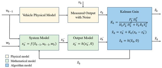
Figure 2.
Simplified illustration of Kalman filtering process.
The state and observation equation of nonlinear systems are usually expressed as
where represents the system state at time and at time ; the control input at time ; and the measured output at time . and represent the process and measurement noise, respectively. Both the process and measurement noise are assumed to be independent Gaussian white noise.
When using the EKF, the state matrix and the noise matrix are the Jacobian matrices obtained by taking partial derivatives of the nonlinear function at time . Similarly, the observation matrix and the measurement noise matrix are the Jacobian matrices of the nonlinear function , as shown in the following:
The EKF algorithm can be summarized as follows:
State prediction equation:
State covariance prediction equation:
Kalman gain equation:
State update equation:
Covariance update equation:
where, denotes the predicted state at time ; the prior estimated state at time ; and the posterior estimated state at time . denotes the predicted state covariance at time ; the prior covariance at time ; and the posterior covariance at time . is the Kalman gain at time , while is the observed output at time . represents the variance of the process noise at time ; is the variance of the measurement noise at time ; and , .
Please note that a small value indicates high model accuracy, suggesting that the system’s predictions are close to real values. If is too small, it may overlook dynamic system changes, leading to poor adaptation. Conversely, if is too large, the confidence in the model’s predictions decreases, relying more on past data, which can increase measured noise. A large indicates lower confidence in the measurements. If is too large, the sensor data become unreliable, reducing estimation accuracy. If is too small, the system may overly trust noisy data, making it more sensitive to changes and increasing errors. Proper tuning of both and is necessary to balance the model’s prediction and measurement reliability.
2.3. Discrete Vehicle System Model
Based on the above EKF algorithm, combined with the vehicle longitudinal model and the suspension vibration model, the state variables and the measured outputs are defined as and , respectively, and the control input . To simplify the system, it is assumed that when the body pitch angle is small, which is usually the case. Also, a quasi-dynamic model of suspension is adopted to avoid a high frequency of noise. Then, the discrete system is given by
where the state matrix is
where represents the vehicle longitudinal speed at time step k−1.
The input matrix is
The observation matrix is
The matrices for process and measurement noise are and , where and . It is assumed that the process and measurement noise are normally distributed.
3. Numerical Simulation Tests and Real-Vehicle Application Validation
3.1. CarSim and Simulink Co-Simulation
In order to validate the developed EKF and to assess the performance of the vehicle pitch attitude estimation, a joint simulation using CarSim and Simulink is adopted. The vehicle longitudinal dynamics and suspension model and the road gradient model are constructed using the CarSim software package (Version: 2019.0), while the vehicle attitude angle estimation by EKF and the vehicle longitudinal speed control are modelled in Simulink. The simulation configuration is illustrated in Figure 3.
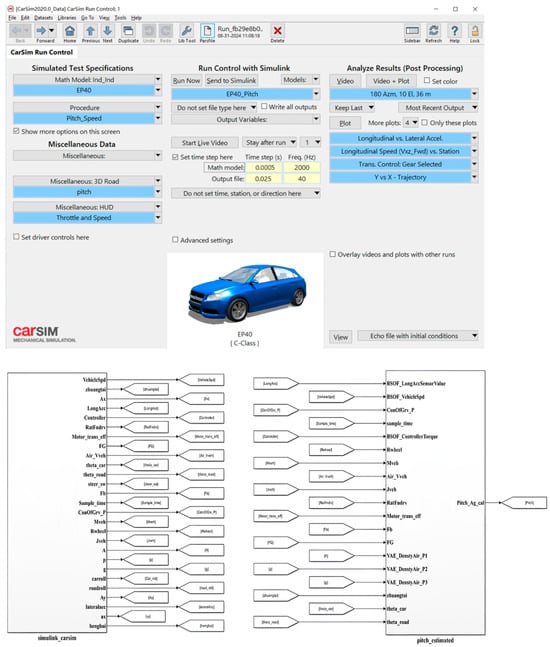
Figure 3.
Joint simulation model using CarSim and Simulink.
In the joint simulation, the vehicle model as in CarSim supplies real-time signals of the vehicle speed and acceleration to the state observer as in the simulation, thereby realizing real-time estimations of the attitude angle. In the meantime, the speed controller in Simulink provides control inputs like the accelerator and brake pedals and the steering angle to the vehicle model in CarSim, ensuring comprehensive numerical tests under various operational scenarios. This paper also compares the proposed EKF approach with the existing low-pass filtering and least squares methods. The simulation results prove the efficiency of the algorithm and the precision of the estimations. The parameters of the vehicle used in this paper are given in Table 1.

Table 1.
Vehicle information.
The simulation results for an REEV ascending a 9° slope are given in Figure 4. The red line denotes the actual pitch attitude angle and the blue line denotes the estimated angle via EKF. The black line and green line represent the estimation of the respective low-pass filtering and least squares methods. For comparison purposes, the vehicle suspension dynamics do not integrate with these two methods. The simulation data reveals that all three algorithms can effectively follow the variation of the pitch attitude eventually, but there are noticeable differences in their tracking accuracy and responsiveness.
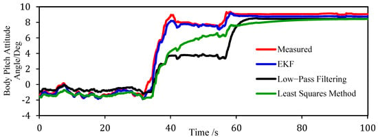
Figure 4.
Estimation results under 9° uphill conditions.
For the first 20s, the vehicle drives on a flat section with minimal slope variation. Thus, the vehicle attitude is predominantly determined by the acceleration (and/or the deceleration) of the vehicle. Clearly, the EKF estimation is nearer to the real attitude angle than those of the low-pass filtering and the least squares methods. This high performance of the EKF is due to the consideration of the suspension system dynamics, with which the pitch motion is readily captured. Between 20 s and 40 s, the vehicle travels on a slope varying significantly. At this time, the vehicle attitude angle is primarily affected by the road gradient. It can be seen that the EKF outperforms the other two methods in terms of its tracking accuracy. This advantage stems from the fact that the EKF can dynamically balance the system model and the sensor measurement. Moreover, the fixed bandwidth design of the low-pass filtering may inadvertently mask useful information. As a consequence, the proposed EKF maintained an error level below 0.5° in subsequent simulations, offering a reliable estimation.
In Figure 5, numerical test results for an REEV descending a 12° downhill are given, where the line type and line color definitions are the same as those in Figure 4. The vehicle travels on a rather steep slope during the initial 40s. The simulation reveals the superiority of the EKF in term of attitude angle estimation. This is attributable to the fact that the vehicle attitude is predominantly affected by the road gradient, and that the Kalman filter can adapt to the slope change more quickly than the other methods. From 18s to 25s, the EKF can effectively capture the pitch angle fluctuations when the vehicle transitions from deceleration to acceleration rapidly, indicating the significance of the pitch motion being introduced by the weight transfer via the suspension. Between 40s and 100s, the vehicle attitude angle estimation of the EKF closely align with the actual values, with errors being less than 0.5°.
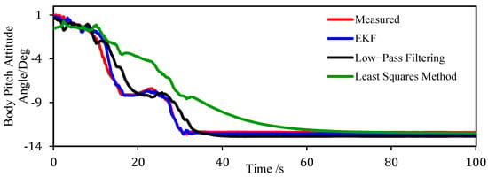
Figure 5.
Estimation results under 12° downhill conditions.
Table 2 presents a quantitative comparison of the RMSE values for the EKF, low-pass filtering, and least squares methods. The results indicate that the EKF consistently outperforms both the low-pass filtering and least squares methods in terms of estimation accuracy, as evidenced by its lower RMSE values. This highlights the superior performance of the EKF, particularly in dynamic driving conditions, where it provides more reliable attitude angle estimates.

Table 2.
Comparison of RMSE for EKF, low-pass filtering, and least squares methods.
In conclusion, the proposed EKF-based attitude angle estimation method demonstrates both accuracy and stability, making it highly applicable in real-world scenarios. It is particularly effective when the attitude angle is significantly influenced by factors such as road gradient and suspension dynamics.
3.2. Real-Vehicle Application and Field Tests
During the real-vehicle validation phase, the attitude angle estimation algorithm is first implemented and integrated into the powertrain domain control system (PDCS) controller of the mass-production Neta S vehicle (Neta is a brand of Hozon New-Energy Automobile Ltd. (Tongxiang, China), which is a Chinese car company). Subsequently, the estimated attitude angle was subject to some rule-based constrains for overall system integration purposes. Finally, real-world validations were performed under two distinct conditions, i.e., real-road tests and turning bench tests, as shown in Figure 6.
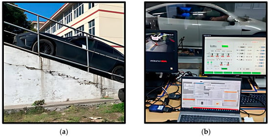
Figure 6.
Real-vehicle validation tests. (a) Description of vehicle on real-world slope test; (b) Description of vehicle on turning bench and calibration test.
The real vehicle validation results are presented in Figure 7 and Figure 8, in which the red line represents the results of IMU sensors, while the black line shows the EKF results. Figure 7 shows the results of vehicle driving on a Moganshan (in the east part of China) mountain road with more obviously steep slopes. By contrast, Figure 8 indicates those of the vehicle undergoing a turning bench test, where the gradient changes are more moderate. It can be seen from Figure 7 that the estimates closely follow the true vehicle attitude angle as measured by high-precision IMUs. This confirms that the attitude angle estimation using the EKF has a good real-time performance. Similarly, Figure 8 reveals that even on a road with minimal gradient fluctuations, the EKF can still characterize the vehicle pitch motion correctly. The attitude angle deviation from the IMU measurements is less than 1.5°. This confirms the high performance of the EKF approach.
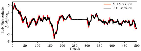
Figure 7.
Moganshan mountain road test.
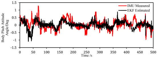
Figure 8.
Turning bench validation test.
The screenshots of the calculated fuel levels for the Neta S vehicle are given in Figure 9 and Figure 10. These fuel level calculations are corrected with the predicted or measured body attitude angle to account for the fuel level inclination and therefore are referred to as the EKF-based and IMU-based fuel levels hereafter. A comparison of the EKF-based fuel level with the IMU-based level is also shown. Figure 9 shows the fuel level comparison under uphill and downhill conditions, while Figure 10 shows the same under rapid acceleration and deceleration conditions. Both figures reveal a high degree of consistency between the fuel levels derived from these two methods. Consequently, the proposed EKF algorithm holds promise for practical deployment, potentially substituting for expensive IMU sensors in estimating fuel levels of REEVs. By effectively delivering the essential attitude angle, specifically the pitch angle, the system can meet the accuracy requirements for fuel remaining range estimation. In addition, the EKF-based approach responds in time to sudden changes in the differences of the body attitude angle and the road slope when the vehicle accelerates and decelerates rapidly, avoiding abnormal jumps in the remaining fuel range calculations and enhancing the reliability in the overall range estimation.
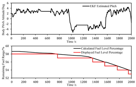
Figure 9.
Comparison of fuel level under uphill and downhill conditions.
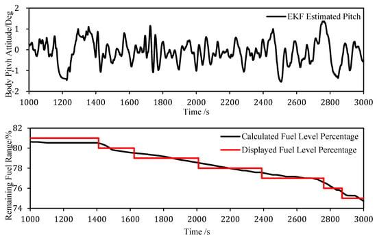
Figure 10.
Comparison of fuel level during sudden acceleration and deceleration.
4. Conclusions
Addressing the critical need for precise fuel range estimation for REEVs, this paper has proposed a sophisticated EKF approach for complex driving conditions. Particularly, the vehicle suspension model is included to handle sudden acceleration (and/or deceleration) situations. To verify the proposed approach, a collaborative simulation using CarSim and Simulink was performed. The EKF algorithm was also assessed with the real vehicle tests on a turning bench and on a sloping road. All these tests validate the effective of the EKF method. It significantly improves the estimation accuracy of the vehicle attitude angle, specifically when coupled with the pitch angle. In addition to its stable estimation across diverse road conditions, it can also efficiently capture dynamic shifts in pitch angle induced by weight transfer. Finally, the algorithm was engineered and implemented into a mass-produced Neta S vehicle, replacing the original expensive IMU sensors. This integration provides essential real-time attitude angle data sufficient for accurate fuel range prediction. In actual vehicle applications, the estimation algorithm not only meets the accuracy requirements of fuel range prediction but also prevents distortions of the remaining fuel calculation, thereby achieving a strategic balance between performance and cost-effectiveness.
While the proposed method has demonstrated success in practical applications, several potential challenges remain. One key issue is ensuring the stability and consistent performance of the algorithm across varying operational conditions, particularly in extreme and complex driving scenarios. The algorithm must maintain reliability in all driving environments. Future research will focus on enhancing the algorithm’s adaptability to noise and disturbances, improving robustness under diverse drives. Additionally, refining the model to improve estimation accuracy—such as incorporating more degrees of freedom like tire stiffness and vehicle sideslip angle—will be crucial for addressing these challenges.
Author Contributions
Investigation, Y.W.; formal analysis, H.H.; methodology and validation, Y.X.; resources and project administration, H.Z.; software and visualization, R.W.; review and editing, Z.Q. and S.S.; supervision, S.S. All authors have read and agreed to the published version of the manuscript.
Funding
This research received no external funding.
Institutional Review Board Statement
Not applicable.
Informed Consent Statement
Not applicable.
Data Availability Statement
The original contributions presented in the study are included in the article. Further inquiries can be directed to the corresponding author.
Acknowledgments
The authors give appreciations for the comments from reviewers so that the quality of the paper improved greatly.
Conflicts of Interest
Ye Wang, Yan Xiao, Honglei Zhang, and Rui Wang are employees of New Energy Automobile Co., Ltd. The remaining authors declare that the research was conducted in the absence of any commercial or financial relationships that could be construed as potential conflicts of interest.
Abbreviations
The following abbreviations are used in this manuscript:
| APU | Auxiliary Power Unit |
| CAN | Controller Area Network |
| DOF | Degree of Freedom |
| EKF | Extended Kalman Filter |
| ICE | Internal Combustion Engine |
| IMU | Inertial Measurement Unit |
| KLF | Kalman Filter |
| LOB | Leuenberger Observer |
| REEV | Range-Extended Electric Vehicle |
| RLS | Recursive Least Squares |
| SMO | Sliding Mode Observer |
| UKF | Unscented Kalman Filter |
Appendix A

Table A1.
List of symbols.
Table A1.
List of symbols.
| Symbol | Description |
|---|---|
| Longitudinal acceleration of the vehicle | |
| Damping of the front suspension | |
| Damping of the rear suspension | |
| Rolling resistance coefficient | |
| Gravitational acceleration | |
| Height of the center of mass of the vehicle | |
| Stiffness of the front suspension | |
| Stiffness of the rear suspension | |
| Wheelbase of the vehicle | |
| Distance from the front axle to the center of mass of the vehicle | |
| Distance from the rear axle to the center of mass of the vehicle | |
| Mass of the vehicle | |
| System control at time k−1 | |
| Measurement noise at time k | |
| Longitudinal speed of the vehicle | |
| Process noise at time k | |
| System state at time k | |
| System state at time k−1 | |
| Predicted system state at time k | |
| Estimated system state at time k | |
| Estimated system state at time k | |
| System measured output at time k | |
| Frontal area of the car | |
| System state matrix at time k | |
| Equivalent damping of the vehicle suspension system | |
| Aerodynamic drag coefficient | |
| Axle driving force | |
| Vertical load on the front wheel | |
| Vertical load on the rear wheel | |
| Observation matrix at time k | |
| Equivalent stiffness of the vehicle suspension system | |
| Kalman gain at time k | |
| Predicted system state covariance at time k | |
| Estimated system state covariance at time k | |
| Estimated system state covariance at time k−1 | |
| Variance of process noise at time k−1 | |
| Wheel radius | |
| Variance of measurement noise at time k | |
| Sampling time | |
| Measurement noise matrix at time k | |
| Process noise matrix at time k | |
| Angle of vehicle slop caused by road gradient | |
| Air density | |
| Angle of vehicle attitude | |
| Angle of vehicle pitch due to weight transfer |
References
- Bonnedahl, T. Road Slope Estimation using a Longitudinal Accelerometer and Kalman Filtering. Master’s Thesis, Lund University, Lund, Sweden, 2010. [Google Scholar]
- Zhang, Z. Research on Algorithm of Vehicle Dynamics State Parameter Estimation. Master’s Thesis, Hunan University, Changsha, China, 2021. [Google Scholar]
- Li, X. Research on State Estimation Algorithm for Four-Wheel Independent Drive Electric Vehicles. Master’s Thesis, Chongqing University, Chongqing, China, 2018. [Google Scholar]
- Lin, C.; Wang, G.; Cao, W.; Zhou, F. Research on State Estimation of Distributed Drive Electric Vehicles Based on LO-EKF Algorithm. J. Automot. Eng. 2014, 36, 1316–1320. [Google Scholar]
- Hashemi, E.; Zarringhalam, R.; Khajepour, A.; Melek, W.; Kasaiezadeh, A.; Chen, S. Real-time estimation of the road bank and grade angles with unknown input observers. Veh. Syst. Dyn. 2017, 55, 646–667. [Google Scholar] [CrossRef]
- Shi, G. Research on Identification of Commercial Vehicle Dynamics State and Stability Coordination Control. Ph.D. Thesis, Jilin University, Changchun, China, 2018. [Google Scholar]
- Jiang, K.; Victorino, A.C.; Charara, A. Adaptive Estimation of Vehicle Dynamics Through RLS and Kalman Filter Approaches. In Proceedings of the 2015 IEEE 18th International Conference on Intelligent Transportation Systems, Gran Canaria, Spain, 15–18 September 2015; pp. 1741–1746. [Google Scholar] [CrossRef]
- Jiang, S.; Wang, C.; Zhang, C.; Bai, H.; Xu, L. Adaptive estimation of road slope and vehicle mass of fuel cell vehicle. ETransportation 2019, 2, 100023. [Google Scholar] [CrossRef]
- Gao, L.; Wu, Q.; He, Y. Road slope estimation for heavy-duty vehicles under the influence of multiple source factors in real complex road environments. Mech. Syst. Signal Process. 2024, 208, 110973. [Google Scholar] [CrossRef]
- Du, Y. Research on Methods for Estimating Commercial Vehicle Mass and Road Slope. Master’s Thesis, ChangAn University, Xi’an, China, 2017. [Google Scholar]
- Sun, W.; Fu, X.; Tang, K.; Huang, B. Joint Estimation of Longitudinal Vehicle Speed and Slope for Four-Wheel Independent Drive Vehicles. J. Wuhan Univ. Technol. (Transp. Sci. Eng.) 2017, 39, 29–33. [Google Scholar]
- Lingman, P.; Schmidtbauer, B. Road Slope and Vehicle Mass Estimation Using Kalman Filtering. Veh. Syst. Dyn. 2002, 37, 12–23. [Google Scholar] [CrossRef]
- Zeng, X.; Qian, Q.; Song, D.; Gu, J.; Yuan, W. Algorithm and Implementation of Slope Estimation Based on Acceleration Correction. Automot. Eng. 2020, 42, 9. [Google Scholar]
- Wenzel, T.A.; Burnham, K.J.; Blundell, M.V.; Williams, R.A. Dual extended Kalman filter for vehicle state and parameter estimation. Veh. Syst. Dyn. 2006, 44, 153–171. [Google Scholar] [CrossRef]
- Heidfeld, H.; Scheunemann, M.; Kasper, R. UKF-based State and tire slip estimation for a 4WD electric vehicle. Veh. Syst. Dyn. 2019, 58, 1479–1796. [Google Scholar] [CrossRef]
Disclaimer/Publisher’s Note: The statements, opinions and data contained in all publications are solely those of the individual author(s) and contributor(s) and not of MDPI and/or the editor(s). MDPI and/or the editor(s) disclaim responsibility for any injury to people or property resulting from any ideas, methods, instructions or products referred to in the content. |
© 2025 by the authors. Published by MDPI on behalf of the World Electric Vehicle Association. Licensee MDPI, Basel, Switzerland. This article is an open access article distributed under the terms and conditions of the Creative Commons Attribution (CC BY) license (https://creativecommons.org/licenses/by/4.0/).